operation and maintenance manual - all categories on...
TRANSCRIPT
Operation and Maintenance Manual
PMMI Show Machine
Model: PAC-4R5
Serial No. 10669 August 2009
Copyright 2009 All Rights Reserved
9511 River Street • Schiller Park, IL 60176 • 847 678-9034 • www.arpacgroup.com


WARRANTY
ARPAC warrants the stretch wrapping machines of its manufacture to be free from defects in material or workmanship for a period of three years from date of shipment from ARPAC’s factory, provided that:
1. Such equipment is given normal and proper usage.
2. It is still owned by the original buyer.
3. The Products have been operated in accordance with generally approved practice and in accordance with ARPAC’s specifications and instructions.
4. No repairs, alterations, or replacements have been made by others without ARPAC’s prior written approval.
5. Genuine ARPAC repair components are used during the warranty period.
ARPAC’s liability under this warranty or in connection with any other claim relating to the Products shall be limited to the repair or, at ARPAC’s option, the replacement of any Products, parts or components thereof which are returned to ARPAC freight prepaid and which are defective in material or workmanship.
The Buyer shall notify ARPAC immediately of any defective parts and ARPAC shall thereupon correct the defect or defects. If such correction requires the replacement of a defective part or parts, ARPAC will supply same F.O.B. its factory.
If warranty parts are required, ARPAC will, at its discretion, repair or replace any defective stretch wrapping parts with a charge to a valid purchase order number. Defective parts, with a valid Return Material Authorization number obtained from ARPAC’s service department, must be returned to ARPAC within thirty (30) days of warranty part shipment, freight prepaid, to receive a credit to this purchase order number. Failure to do so will result in zero credit being applied to the original P.O. or may void this warranty. All returned parts are subject to factory inspection. ARPAC reserves the right to determine the cause of failure and the subsequent inclusion of the replacement part under this warranty. Defective parts that have been disassembled or damaged during removal or otherwise tampered with will not be covered under this warranty.
Damage caused during transport is the responsibility of the carrier and is not covered under this warranty. All damages detected upon receipt of equipment should be reported immediately to the carrier and ARPAC should be notified.
ARPAC shall in no event be held liable for any direct, indirect, incidental or consequential damage, losses, expenses or delay caused by defective parts and will not accept any charges for work performed by Buyer in making adjustments or repairs to the Products unless such work has been authorized in writing by ARPAC. Except as stated herein, ARPAC makes no other warranty, expressed or implied, nor does it assume or authorize anyone else to assume for it, any other obligation relating to our products or any products.
Any Product or component not of ARPAC’s own manufacture is not covered by this warranty and is sold to Buyer only with such warranty, if any, as is provided by such manufacturer, to the extent ARPAC and its assigns are able or entitled to enforce such warranty. Such items are not warranted by ARPAC in any way.
When components are sold to be assembled in combination of Buyer’s design, the warranty shall be limited to each separate component and shall not apply to any combinations or components.
EXCEPT AS EXPRESSLY STATED ABOVE, ARPAC MAKES NO WARRANTY, EXPRESS OR IMPLIED, WHETHER OF MERCHANTABILITY OR FITNESS FOR ANY PARTICULAR PURPOSE OR USE OR OTHERWISE, ON THE PRODUCTS, OR ANY PARTS OR LABOR FURNISHED DURING THE SALE, DELIVERY OR SERVICING OF THE PRODUCTS.
ARPAC factory trained, qualified technical services personnel are available for start-up and instructional assistance. If the customer does not utilize ARPAC personnel for this function, ARPAC is only liable for replacement of defective parts, not for labor or expenses necessary to adjust any problems during the start-up period.
ARPAC personnel are available for ARPAC equipment training, either on-site/hands on or in classroom environment, supported by visual aids and literature, to be contracted for by a separate purchase order.

PRE – STRETCH ROLLER WARRANTY
All products manufactured and sold by Bryant Products, Inc. (“Bryant”) are subject to Bryant’s Standard Conditions Of Sale, a copy of which is attached or has been furnished to you. In consideration of future orders to be received from you, Bryant will modify the “Warranty” section of its Standard Condition Of Sale and grant to your company the following Limited Lifetime Warranty on the lagging compound on Bryant rollers:
The Bryant lagging compound on rollers of Bryant’s manufacture is warranted to be free from defects in material and workmanship, and to perform as required in properly maintained powered pre-stretch film delivery systems. In order to validate this Warranty, the machine on which the Bryant rollers are installed must be registered with Bryant within (90) days of receipt of the rollers, and in the event of any claims for defective rollers must be returned to Bryant, prepaid. If Bryant determines the lagging compound to be defective in material or workmanship, Bryant will relag the rollers free of charge. Bryant does not, however, warrant the rollers, shafts or cores against physical damage, corrosion, abuse or negligence. Damages caused by inadequate air or voltage supply, normal wear, misuse or neglect are not covered by this Warranty. Damages caused during transport are the responsibility of the carrier and are not covered under this Warranty.
Your sole remedy under this Warranty shall be the repair or replacement of the lagging.
BRYANT SHALL IN NO EVENT BE LIABLE FOR ANY OF YOUR CONSEQUENTIAL OR INCIDENTAL DAMAGES. BRYANT MAKES NO OTHER WARRANTY OF ANY KIND WHATEVER, EXPRESSED OR IMPLIED, AND ALL IMPLIED WARRANTIES AND MERCHANTABILITY AND FITNESS FOR A PARTICULAR PURPOSE WHICH EXCEED THE OBLIGATION STATED ABOVE ARE HEREBY DISCLAIMED. All other terms and conditions contained in Bryant’s Standard Conditions Of Sale, or within the “Warranty” section thereof, which are not expressly modified by this document, are unchanged and unaffected. Please note that parts cannot be returned without an RGA number. Please contact Bryant in the case of any claim or return.
WARRANTY REGISTRATION FORM
Company Name ______________________________ Machine Model# __________________________
Name of Contact _____________________________ Machine Serial # __________________________ Address ___________________________________ Machine in Service Date ____________________
___________________________________ Signature ________________________________ Date _________________
Fill out and return this form to: Bryant Products, Inc.
Warranty Registration Attn: Tamara PO Box 270
Ixonia, WI 53036 800-825-3874 tel: 920-206-6920 fax: 920-206-6929 [email protected]


ARPAC GROUP • 9511 West River Street, Schiller Park, IL 60176 • PHONE: (847) 678-9034 • www.arpacgroup.com i
Table of Contents Section Page
Installation Instructions ...................................................................................I-0
Site Preparation ...................................................................................................I-1
Receipt of Machine..............................................................................................I-2
Base and Turntable .............................................................................................I-3
Top Sheet Dispenser ...........................................................................................I-6
Control Module ....................................................................................................I-7
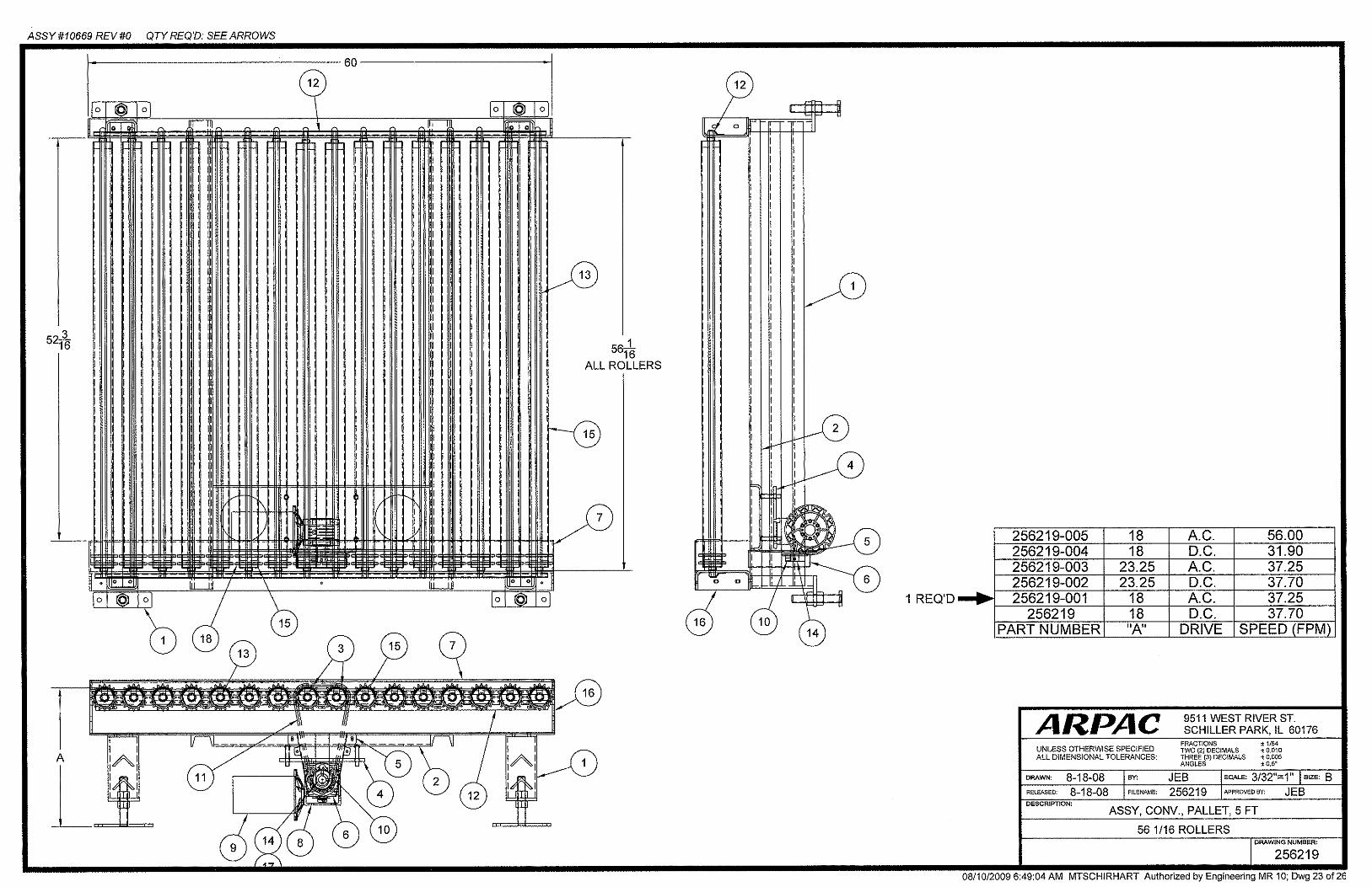
Infeed Powered Conveyor...................................................................................I-9
Exit Powered Conveyor.....................................................................................I-10
Safety Fence and Gate ......................................................................................I-11
Verifying Machine Settings...............................................................................I-11
Emergency Stop Verification............................................................................I-11
Film Carriage Lower Travel Limit Verification.................................................I-11
Warranty..................................................................................................................
Layout Drawing...................................................................................................
1 Introduction......................................................................................................1-0
Using This Manual ..............................................................................................1-1
Manual Design ....................................................................................................1-2
ARPAC GROUP • 9511 West River Street, Schiller Park, IL 60176 • PHONE: (847) 678-9034 • www.arpacgroup.com ii
Table of Contents Section Page
2 Safety ...................................................................................................................2-0
Safety Information ..............................................................................................2-1
Personnel Instructions.....................................................................................2-1
Energy Hazards ..............................................................................................2-2
Guarding and Doors ........................................................................................2-3
Interfacing Equipment .....................................................................................2-3
Warning Labels...................................................................................................2-4
3 Mechanical Sub-Assemblies .................................................................3-0
Top Sheet Dispenser ..........................................................................................3-1
Base and Turntable ............................................................................................3-2
Film Clamp/Cut Device....................................................................................3-6
Film Rope Wipe Arm .......................................................................................3-6
Tower & Control Cabinet....................................................................................3-7
Film Saver ...........................................................................................................3-8
Dancer Arm .....................................................................................................3-9
Infeed Powered Conveyor................................................................................3-10
Exit Powered Conveyors..................................................................................3-11
Safety Fence and Gate .....................................................................................3-12

ARPAC GROUP • 9511 West River Street, Schiller Park, IL 60176 • PHONE: (847) 678-9034 • www.arpacgroup.com iii
Table of Contents Section Page
4 Operator Controls ........................................................................................4-0
Main Power Disconnect Switch.........................................................................4-1
Master Air Supply Regulator .............................................................................4-1
Emergency Stop Push-Pull Button ...................................................................4-1
Power On Push Button.......................................................................................4-2
Cycle Stop/Reset Push Button ..........................................................................4-2
Cycle Start/Restart Push Button .......................................................................4-2
Rewrap Push Button ..........................................................................................4-3
Turntable Home Push Button ............................................................................4-3
Carriage Jog Selector Switch ............................................................................4-4
Cycle Select A B C Selector Switch ..................................................................4-4
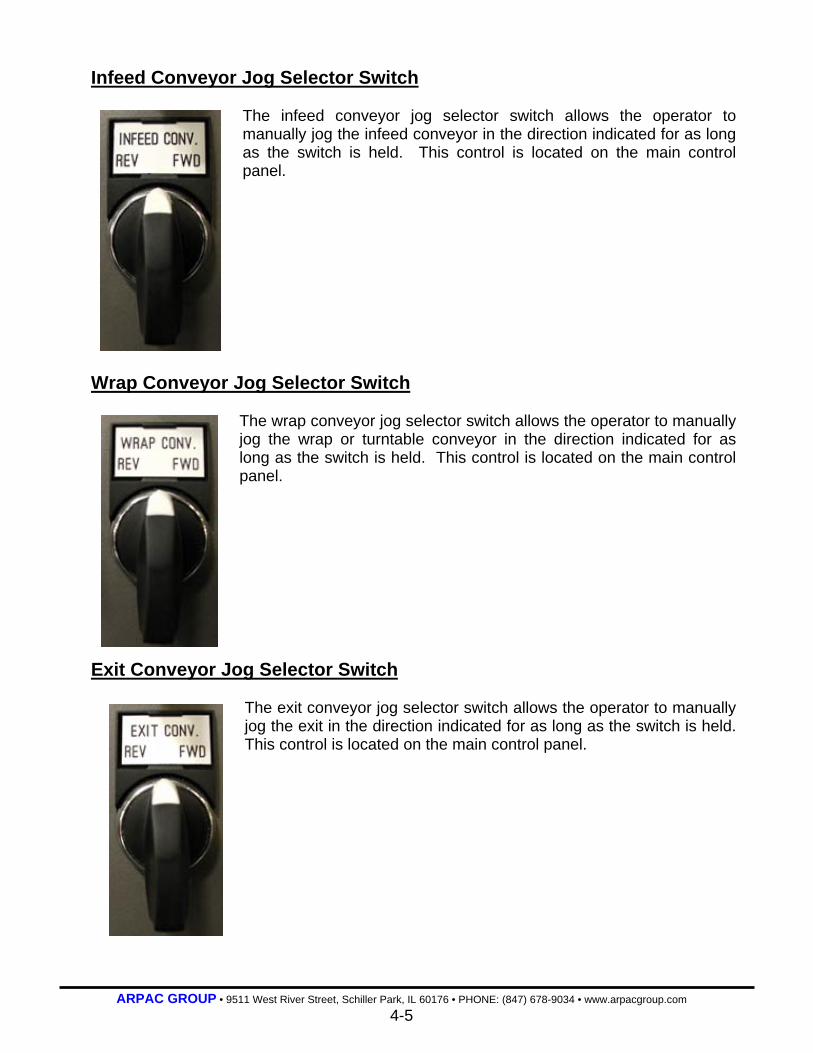
Infeed Conveyor Jog Selector Switch...............................................................4-5
Wrap Conveyor Jog Selector Switch ................................................................4-5
Exit Conveyor Jog Selector Switch ..................................................................4-5
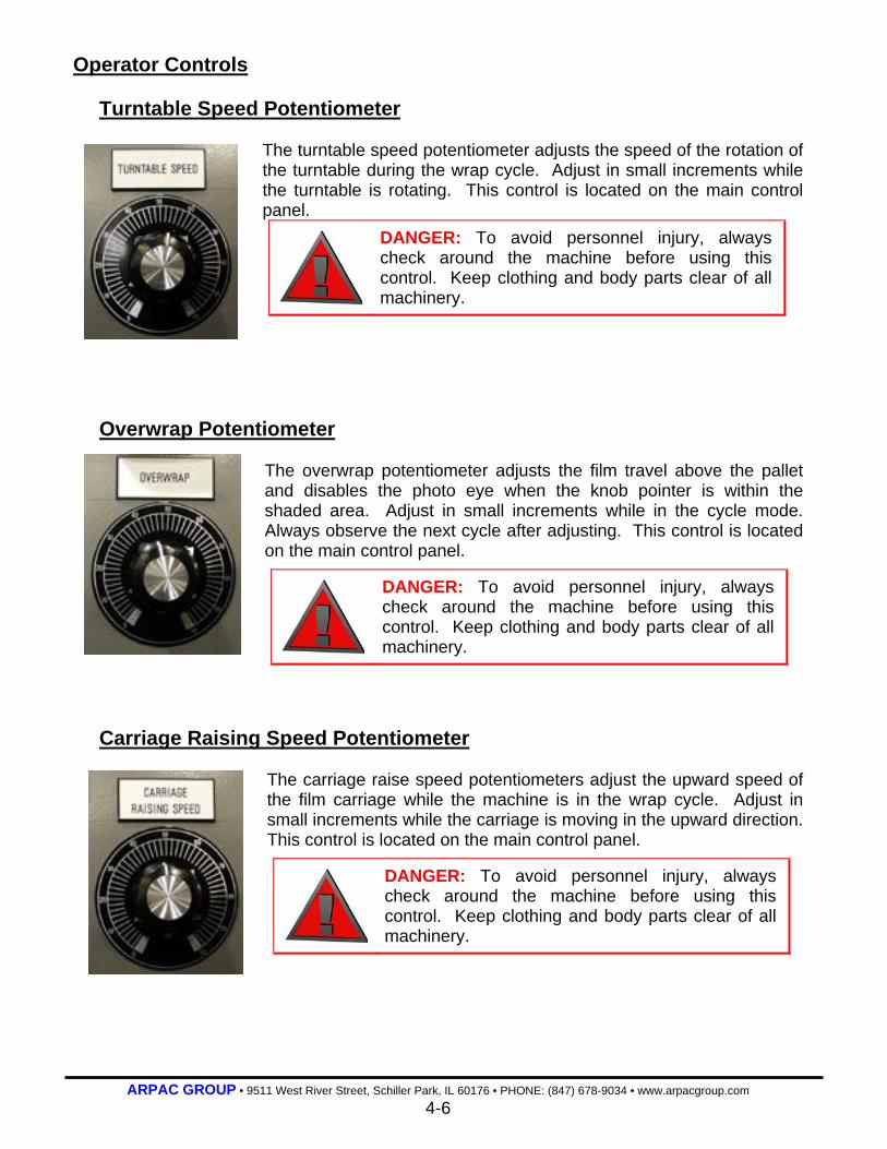
Turntable Speed Potentiometer ........................................................................4-6
Overwrap Speed Potentiometer ........................................................................4-6
Carriage Raise Speed Potentiometer................................................................4-6
Load Compression Potentiometer ....................................................................4-7
Carriage Lower Speed Potentiometer...............................................................4-7
TSD Up Down Selector Switch ..........................................................................4-7
ARPAC GROUP • 9511 West River Street, Schiller Park, IL 60176 • PHONE: (847) 678-9034 • www.arpacgroup.com iv
Table of Contents Section Page
4 Operator Controls ........................................................................................4-0
Manual Sheet Cycle Push Button......................................................................4-8
Operator Interface ..............................................................................................4-8
Base Wrap Counter and op Wrap Counter .......................................................4-9
Adjustment Handles...........................................................................................4-9
Swift Change Film Mandrel................................................................................4-9
Alarm Horn (optional)...........................................................................................4-10
Stack Light ........................................................................................................4-10
Air Flow Control Valves ...................................................................................4-10
5 Operating Procedures ...............................................................................5-0
Initial Startup.......................................................................................................5-1
Quick Startup ......................................................................................................5-2
Emergency Shutdown........................................................................................5-3
Short-Term Shutdown........................................................................................5-3
Long-Term Shutdown.........................................................................................5-3
Film Roll Installation ..........................................................................................5-4
Film Threading....................................................................................................5-5
Film Threading Diagram ..................................................................................5-5
(Continued on the next page)
ARPAC GROUP • 9511 West River Street, Schiller Park, IL 60176 • PHONE: (847) 678-9034 • www.arpacgroup.com v
Table of Contents Section Page
5 Operating Procedures ...............................................................................5-0
Product Setup Procedures ................................................................................5-7
Product Setup Chart........................................................................................5-9
Operator Interface ............................................................................................5-10
Navigating the Screens .................................................................................5-10
Selecting Product ..........................................................................................5-11
Viewing, Changing and Saving Parameters ..................................................5-12
Messages ......................................................................................................5-14
Timers ...........................................................................................................5-14
Machine Counters (optional)............................................................................5-15
Maintenance..................................................................................................5-16
Main Menu ....................................................................................................5-17
Screen Brightness .........................................................................................5-18
Wrap Pattern Descriptions (Optional).............................................................5-18
A Wrap Pattern (Not Applicable) .......................................................................5-19
B Wrap Pattern..............................................................................................5-19
C Wrap Pattern (Bypass Mode) ........................................................................5-19

ARPAC GROUP • 9511 West River Street, Schiller Park, IL 60176 • PHONE: (847) 678-9034 • www.arpacgroup.com vi
Table of Contents Section Page
6 Troubleshooting............................................................................................6-0
Abnormal Running Conditions..........................................................................6-1
Turntable Will Not Rotate ................................................................................6-1
Film Carriage Does Not Rise...........................................................................6-1
Film Carriage Is At Top and Will Not Descend ................................................6-2
Film Does Not Feed During Wrap Cycle .........................................................6-2
Film Carriage Fuse Blows ...............................................................................6-2
Turntable Fuse Blows......................................................................................6-3
Error Messages...................................................................................................6-4
Film Break .......................................................................................................6-4
Gate Door Open (optional) ................................................................................6-4
Film Saver Door Open.....................................................................................6-4
Home Switch Not Sensing...............................................................................6-5
Both Limit Switches Tripped ............................................................................6-5
Carriage Travel Time Exceeded......................................................................6-5
Carriage Past Bottom Limit .............................................................................6-6
Carriage Past Top Limit...................................................................................6-6
Wrap Cycle Time Exceeded ............................................................................6-6
(Continued on the next page)
ARPAC GROUP • 9511 West River Street, Schiller Park, IL 60176 • PHONE: (847) 678-9034 • www.arpacgroup.com vii
Table of Contents Section Page
6 Troubleshooting............................................................................................6-0
Error Messages...................................................................................................6-3
Carriage Travel Time Exceeded (60 sec)........................................................6-7
Safety Eye Blocked While T/Turntable Running..............................................6-7
Wrap Conveyor Ran Too Long........................................................................6-7
Swing Arm Jammed ........................................................................................6-8
T/T Brake Off...................................................................................................6-8
T/T Not At Home Position................................................................................6-8
Film Clamp Open ............................................................................................6-8
Top Sheet Dispenser Not At Home ( UP ).......................................................6-9
Exit Run Too Long...........................................................................................6-9
TSD Not At Top Position For Off Mode ...........................................................6-9
Infeed Run Too Long.......................................................................................6-9
Load Over Run Stopping Position .................................................................6-10
TSD Safety Is Engaged.................................................................................6-10
Film Unwind Run Too Long ...........................................................................6-11
Excessive Time TSD Lower Down Detected (Soft Limit)...............................6-11
Pusher Safety Switch Engaged .....................................................................6-11
ARPAC GROUP • 9511 West River Street, Schiller Park, IL 60176 • PHONE: (847) 678-9034 • www.arpacgroup.com viii
Table of Contents Section Page
7 Maintenance.....................................................................................................7-0
Break-In Period ...................................................................................................7-1
Preventive Maintenance.....................................................................................7-1
Preventive Maintenance Schedule ..................................................................7-1
Walk-Around Safety Inspection .......................................................................7-3
Cleaning Pre-Stretch Rollers ...........................................................................7-3
Drive Chains....................................................................................................7-3
Commutator Rings ..........................................................................................7-3
Lubrication ..........................................................................................................7-3
Lubrication Schedule.......................................................................................7-3
Corrective Maintenance .....................................................................................7-4
Turntable Conveyor Removal..........................................................................7-4
Turntable Conveyor Re-installation .................................................................7-6
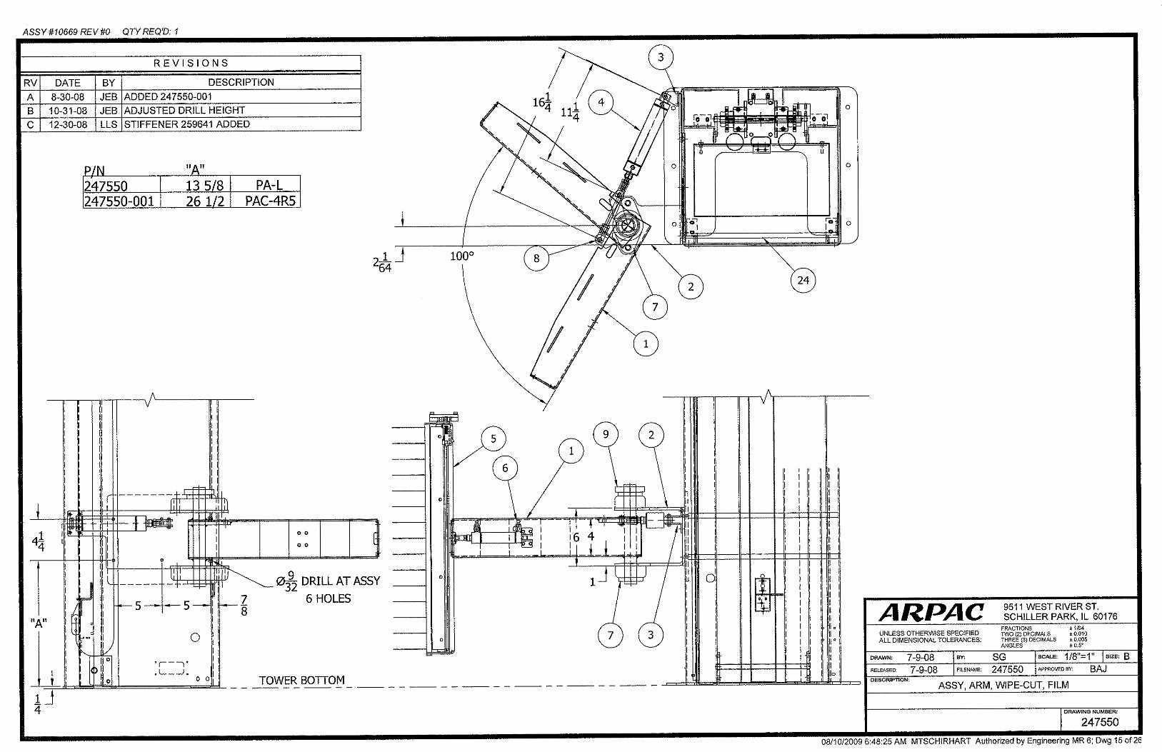
Film Wipe Cut Arm Swing Adjustment.............................................................7-7
8 Glossary of Terms........................................................................................8-0
ARPAC GROUP • 9511 West River Street, Schiller Park, IL 60176 • PHONE: (847) 678-9034 • www.arpacgroup.com ix
Table of Contents Section Page
9 Service Information.....................................................................................9-0
Field Service Policy............................................................................................9-1
Installation Policy ...............................................................................................9-2
Parts Order Form................................................................................................9-4
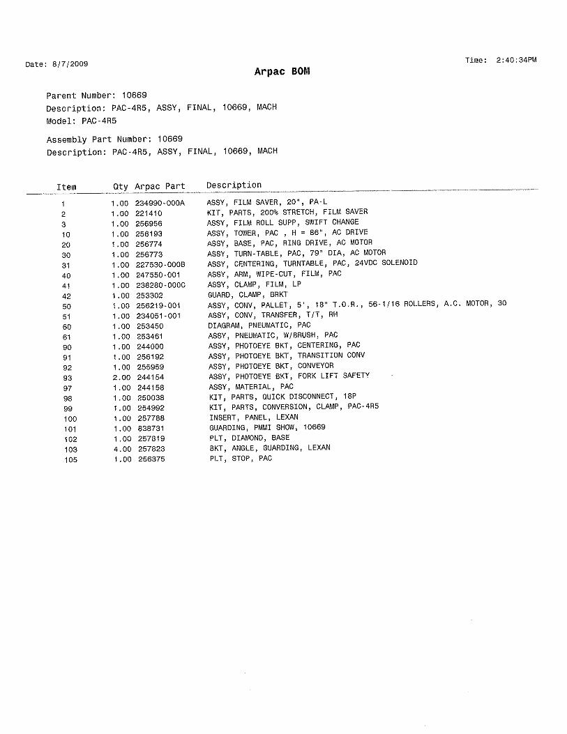
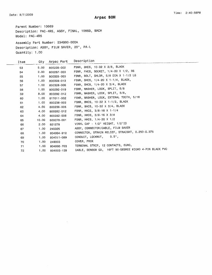
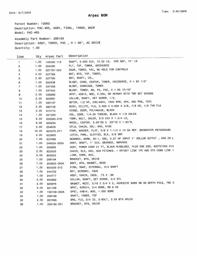
10 Mechanical Assembly Drawings .......................................................10-0
11 Electrical Information...............................................................................11-0
12 Vendor Information....................................................................................12-0
ARPAC GROUP • 9511 West River Street, Schiller Park, IL 60176 • PHONE: (847) 678-9034 • www.arpacgroup.com I-0
SECTION I
Installation Instructions
I-1 Site Preparation I-2 Receipt of Machine I-3 Base and Turntable Conveyor I-6 Top Sheet Dispenser I-7 Control Module I-9 Infeed Powered Conveyor I-10 Exit Powered Conveyor I-11 Verifying Machine Settings
I-11 Emergency Stop Verification I-12 Film Carriage Lower Travel Limit Verification

ARPAC GROUP • 9511 West River Street, Schiller Park, IL 60176 • PHONE: (847) 678-9034 • www.arpacgroup.com I-1
Installation Instructions This section explains how to install the equipment as well as gives a brief overview of the
equipment sub-assemblies and their functions under normal production conditions. See the
machine layout in the front of this manual.
Site Preparation
The site and the immediate surrounding area for the wrapping system must be clean and
clear of all items and debris. All tools used for installation should be placed to the side of
the installation area in an organized manor. The site should be marked as to the exact
placement for the machine. This will provide easier uninterrupted placement of the
equipment with the forklift.
Tools Required: Assorted mechanic’s and electrician’s tools including a hammer drill,
blue Loctite # 242, 12’ Step ladder, (1) 5’ x 1” Steel Rod, (2) 5’ long
lifting straps, 2000 lb. capacity and a forklift truck with a 3000 pound
capacity and a 15’ lift.
Electrical Power: The site for a standard wrapping system requires 240 or 480 volt, 3
phase power with an earth ground. This incoming power will supply
the voltage to the voltage reducing transformer which in turn will
supply the 115 volt ac power required to operate the system.
Pneumatic Power: The site for the wrapping system requires an air supply of 3 cfm @
60-80 psi. The air supply must be clean and dry.

ARPAC GROUP • 9511 West River Street, Schiller Park, IL 60176 • PHONE: (847) 678-9034 • www.arpacgroup.com I-2
Receipt of Machine
DANGER: There are sharp edges and recoil hazards involved in this procedure. Wear the appropriate personal protective equipment for hands and eyes. Stand clear of all bands before cutting them loose.
NOTE: ARPAC is not responsible for shipping damages. All damage claims will be handled between the end-user and the carrier. Upon receipt of the system, all packaging material should be removed and all components and wiring inspected for damage that may have occurred in transit.
If damage is found, please submit a damaged freight claim immediately with the delivering carrier.
ARPAC will replace any damaged items, but replacement is at the expense of the end-user. Compensation must be recovered from the carrier.
1. Inspect the condition of the protective packaging and the overall condition of the
machine to determine if there has been any damage to the equipment.
2. Remove all protective packaging.
3. Inspect the equipment again without the packaging material.

ARPAC GROUP • 9511 West River Street, Schiller Park, IL 60176 • PHONE: (847) 678-9034 • www.arpacgroup.com I-3
Base and Turntable Conveyor
(Continued on the next page)

ARPAC GROUP • 9511 West River Street, Schiller Park, IL 60176 • PHONE: (847) 678-9034 • www.arpacgroup.com I-4
Base and Turntable Conveyor Installation
DANGER: Extreme caution must be exercised during the placement process to prevent injury to personnel or damage to the machine. Make sure all personnel are out of harms way.
1. Place the forklift truck forks into the two access tubes which lead into the transport lift
tubing. These tubes are located on the bottom side of the base. Lift the machine to
remove it from the pallet.
2. Position the base in its final location on the floor.
3. Mark the floor for the positions of the mounting anchors.
NOTE: Anchor the machine per your standard plant procedure. It is recommended that you use ½ -13 concrete anchor bolts. The length of the bolt is determined by the thickness of the concrete floor. Only drill down 75% of the concrete floor thickness as not to break through the bottom of the concrete slab. Also, when drilling stay away a minimum of 12” from the edge of the slab and any surface cracks.
4. Move the base to the side.
5. Drill and set the anchors in the floor.
6. Position and level the base in its final location and bolt it to the floor.
75%
ARPAC FLANGE
5” Minimum Slab Thickness
ARPAC GROUP • 9511 West River Street, Schiller Park, IL 60176 • PHONE: (847) 678-9034 • www.arpacgroup.com I-5
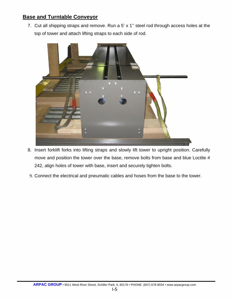
Base and Turntable Conveyor
7. Cut all shipping straps and remove. Run a 5’ x 1’’ steel rod through access holes at the
top of tower and attach lifting straps to each side of rod.
8. Insert forklift forks into lifting straps and slowly lift tower to upright position. Carefully
move and position the tower over the base, remove bolts from base and blue Loctite #
242, align holes of tower with base, insert and securely tighten bolts.
9. Connect the electrical and pneumatic cables and hoses from the base to the tower.

ARPAC GROUP • 9511 West River Street, Schiller Park, IL 60176 • PHONE: (847) 678-9034 • www.arpacgroup.com I-6
Top Sheet Dispenser Installation
DANGER: Extreme caution must be exercised during the placement process to prevent injury to personnel or damage to the machine. Make sure all personnel are out of harms way.
10. Attach 4x4 wood blocks to the forks of lift truck to protect the paint. Place the forklift
truck forks under the top cross member of the top sheet dispenser.
11. Slowly raise the top sheet dispenser assembly by blocking the bottom feet. Once in
the upright position carefully move and position the dispenser over the front of infeed
conveyor in its final location on the floor.
12. Mark the floor for the positions of the mounting anchors.
13. Lift and move the dispenser assembly back .
14. Drill and set the anchors in the floor.
15. Position and level the dispenser in its final location and bolt it to the floor.
ARPAC GROUP • 9511 West River Street, Schiller Park, IL 60176 • PHONE: (847) 678-9034 • www.arpacgroup.com I-7
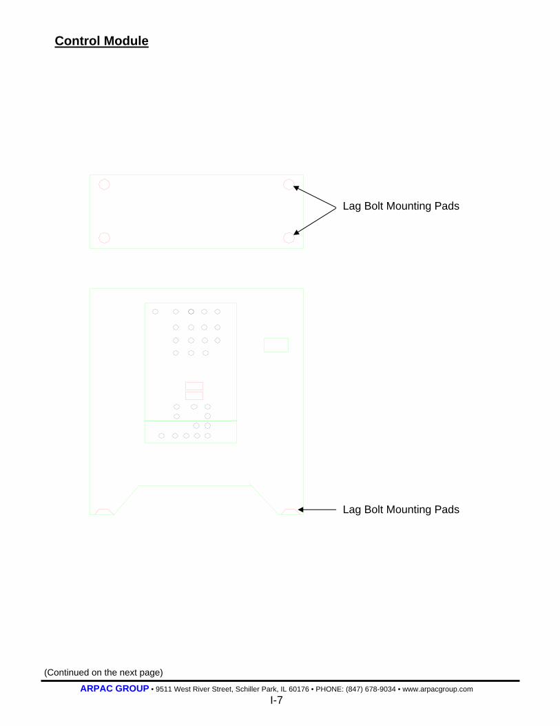
Control Module
Lag Bolt Mounting Pads
Lag Bolt Mounting Pads
(Continued on the next page)

ARPAC GROUP • 9511 West River Street, Schiller Park, IL 60176 • PHONE: (847) 678-9034 • www.arpacgroup.com I-8
Control Module Installation
DANGER: Extreme caution must be exercised during the placement process to prevent injury to personnel or damage to the machine. Make sure all personnel are out of harms way.
1. Position the control module in its final location on the floor.
2. Mark the floor for the positions of the mounting anchors. Use the same anchors as
directed in the base instructions.
3. Move the control module to the side.
4. Drill and set the anchors in the floor.
5. Position and level the control module in its final location and bolt it to the floor.
6. Connect the two gray flex cables from the tower to the control module.
7. Connect the interfacing wires from the system controller to the machine control box
and the power safety switch panel on the side of the control module.
8. Open the control box and check to see that the relays, ribbon cables and wiring plugs
are properly seated.
NOTE: Shipping can cause items to come loose. All wires from the gray flex cables will have to be connected inside of the control box. Each wire should be connected to its corresponding mate.
9. For machines installed in environments at 35 degrees Fahrenheit or less: Check all
fasteners for tightness after they have been installed for a minimum of 24 hours.
Perform this inspection regularly throughout the lifetime of the machine.

ARPAC GROUP • 9511 West River Street, Schiller Park, IL 60176 • PHONE: (847) 678-9034 • www.arpacgroup.com I-9
Infeed Powered Conveyor
Installation
DANGER: Extreme caution must be exercised during the placement process to prevent injury to personnel or damage to the machine. Make sure all personnel are out of harms way.
NOTE: It is critical that the infeed conveyor be positioned squared to the base and 1” from the turntable.
1. Position the infeed conveyor in its final location on the floor.
2. Mark the floor for the positions of the mounting anchors. Use the same anchors as
directed in the base instructions.
3. Move the infeed conveyor to the side.
4. Drill and set the anchors in the floor.
5. Position and level the infeed conveyor with the turntable conveyor and bolt it to the
floor.
6. Connect the electrical cables for the safety photo eye to the tower. Where applicable.
NOTE: If there are several infeed conveyors install them in the previous manor with the highest numbered conveyor next to the turntable conveyor. The other conveyors will mate up in descending numerical order. For example, conveyor number one will be the furthest from the turntable conveyor. This conveyor starts the sequencing of pallet movement into the wrap zone.
Infeed Conveyor
Turntable Conveyor
1” Gap
ARPAC GROUP • 9511 West River Street, Schiller Park, IL 60176 • PHONE: (847) 678-9034 • www.arpacgroup.com I-10
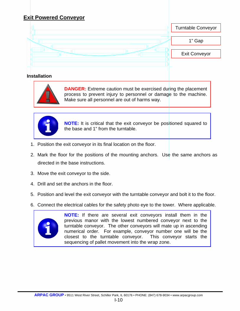
Exit Powered Conveyor
Installation
DANGER: Extreme caution must be exercised during the placement process to prevent injury to personnel or damage to the machine. Make sure all personnel are out of harms way.
NOTE: It is critical that the exit conveyor be positioned squared to the base and 1” from the turntable.
1. Position the exit conveyor in its final location on the floor.
2. Mark the floor for the positions of the mounting anchors. Use the same anchors as
directed in the base instructions.
3. Move the exit conveyor to the side.
4. Drill and set the anchors in the floor.
5. Position and level the exit conveyor with the turntable conveyor and bolt it to the floor.
6. Connect the electrical cables for the safety photo eye to the tower. Where applicable.
NOTE: If there are several exit conveyors install them in the previous manor with the lowest numbered conveyor next to the turntable conveyor. The other conveyors will mate up in ascending numerical order. For example, conveyor number one will be the closest to the turntable conveyor. This conveyor starts the sequencing of pallet movement into the wrap zone.
Turntable Conveyor
Exit Conveyor
1” Gap

ARPAC GROUP • 9511 West River Street, Schiller Park, IL 60176 • PHONE: (847) 678-9034 • www.arpacgroup.com I-11
Verifying Machine Settings This procedure should be performed before the machine is placed into operation.
1. Make sure the machine and the area around the machine is clear of all products and
any other items not directly related to the normal operation of the machine.
2. Inspect the film carriage, film saver and turntable for debris.
3. Ensure all persons in the area of the machine are aware the machine is about to start.
Emergency Stop Verification 1. Pull out the emergency stop push-pull button.
DANGER: Be aware while working with the machine during this time. There are many possibly hazardous moving parts, including chains and sprockets.
2. Set the film carriage speed potentiometer to setting number 3.
3. Turn the film carriage lower/raise selector switch to the RAISE position. The
carriage and film saver should move upward.
NOTE: Movement verifies the E-stop circuit has been reset and there are no faults causing and E-stop condition.
4. Turn the film carriage lower/raise selector switch to the CENTER position.
5. Push the emergency stop push-pull button.
6. Turn the film carriage lower/raise selector switch to the RAISE position. The
carriage and film saver should not make any movement upward.
NOTE: Lack of movement verifies there is an E-stop condition.
(Continued on the next page)
ARPAC GROUP • 9511 West River Street, Schiller Park, IL 60176 • PHONE: (847) 678-9034 • www.arpacgroup.com I-12
Verifying Machine Settings
Film Carriage Lower Travel Limit Verification 1. Set the film carriage lower speed potentiometer to setting number 3.
2. Turn the film carriage lower/raise selector switch to the LOWER position to move
the carriage downward. The carriage will stop when the proximity sensor detects the
magnet.
NOTE: If the carriage does not stop and passes the magnet refer to the Troubleshooting section of this manual.
The upper travel limit is fixed. The lowest travel level that can be set is just above the turntable platform. It is best to set the lower limit with a full roll of film on the film saver and the film carriage lower speed potentiometer set at full speed.

ARPAC GROUP • 9511 West River Street, Schiller Park, IL 60176 • PHONE: (847) 678-9034 • www.arpacgroup.com
1-0
SECTION 1
Introduction
1-1 Using This Manual 1-2 Manual Design
ARPAC GROUP • 9511 West River Street, Schiller Park, IL 60176 • PHONE: (847) 678-9034 • www.arpacgroup.com
1-1
Introduction
This manual is an operations and maintenance manual for ARPAC® packaging equipment.
Use this manual if you are responsible for using, operating and/or maintaining the
equipment. It is organized in a manner that can be easily understood by personnel with
reasonable experience. This manual is designed to provide clear and simple explanations of
safety, daily operating procedures, troubleshooting guidelines and descriptions of machine
parts and controls.
If operated and maintained correctly, this machine is designed to provide the user years of
trouble-free service. It combines up-to-date, state-of-the art technology as well as ARPAC’s
enormous experience in the area of packaging systems.
Using this manual The following features help make this manual simple to use:
Construction The binder on this manual is attractive enough to sit on the shelf in the office, yet rugged
enough to bring into the shop. Tabbed dividers separate the sections of this manual,
providing quick access to a specific area of the text.
Text Notations The titles at the top of every page provide a quick reference as to which section the
manual is opened to.
Graphical Notations
NOTE: Contain additional information to assist personnel in the operation of this machine.
DANGER: Warn the user of possible personnel and/or equipment hazards in the operation and maintenance of this machine.
ARPAC GROUP • 9511 West River Street, Schiller Park, IL 60176 • PHONE: (847) 678-9034 • www.arpacgroup.com
1-2
Manual Design This manual is organized into the following sections:
- Installation Instructions This section gives the recommended
procedure for installing and initially setting up
the equipment.
- Repackaging Instructions This section gives the recommended
procedure for repackaging the equipment.
(extended tower on single base units only)
- Warranty This is the standard ARPAC® warranty
provided with new equipment.
- Machine Layout Drawing The layout drawing provides a visual index of
this manual. Use the layout drawing to find
information on individual assemblies.
- Table of Contents The table of contents is a directory of this
manual.
1 Introduction This section explains how to use the manual.
2 Safety Describes the safety precautions that should
be followed when working with, on or around
the equipment.
3 Mechanical Sub-Assemblies
Describes the features of the individual
mechanical assemblies and their function. It
also provides a brief overview of the
interaction of these assemblies with other
machine components.
4 Operator Controls Explains the purpose and location of all the
controls used to operate the machine.
(Continued on the next page)
ARPAC GROUP • 9511 West River Street, Schiller Park, IL 60176 • PHONE: (847) 678-9034 • www.arpacgroup.com
1-3
Manual Design
5 Operating Procedures This section is dedicated to the operator. It
describes in detail step-by-step procedures for
starting, stopping and operating the equipment
including such operator functions as
changeovers and correcting minor setup
problems.
6 Troubleshooting This section was designed to help the operator
and the maintenance personnel understand
and resolve any possible problems with the
machine. Abnormal running conditions and
error messages are covered in the
troubleshooting section.
7 Maintenance Explains the tasks the operator and the
qualified maintenance person should do in
order keep the machine in top running
condition. It also gives some brief descriptions
of how to repair minor problems.
8 Glossary of Terms This section contains words that pertain to the
equipment, which the operator may not be
familiar with.
9 Service Information This section contains an overview of customer
service. Included are a field service policy,
installation policy and parts ordering
information with an order form.
(Continued on the next page)
ARPAC GROUP • 9511 West River Street, Schiller Park, IL 60176 • PHONE: (847) 678-9034 • www.arpacgroup.com
1-4
Manual Design
10 Mechanical Assembly
Drawings
The mechanical assembly drawings are the
prints for all of the major assemblies on your
machine. In this section, you will find
assembly drawings complete with bill of
materials.
11 Electrical Information Detailed information on the machine’s
electrical engineering. Included are electrical
schematics, an electrical bill of material
complete with manufacturer’s part numbers
and the PLC Program.
12 Vendor Information Here you will find manufacturer’s manuals for
certain components.
ARPAC GROUP • 9511 West River Street, Schiller Park, IL 60176 • PHONE: (847) 678-9034 • www.arpacgroup.com 2-0
SECTION 2
Safety 2-1 Safety Information
2-1 Personnel Instructions 2-2 Energy Hazards 2-3 Guarding and Doors 2-3 Interfacing Equipment
2-4 Warning Labels
ARPAC GROUP • 9511 West River Street, Schiller Park, IL 60176 • PHONE: (847) 678-9034 • www.arpacgroup.com 2-1
Safety Information
Every effort has been made by ARPAC to provide you with a safe machine. This
section describes the safety precautions that should be taken when working with, on or
around the equipment. It is essential that machine operators and maintenance
personnel follow the safety information below.
Personnel Instructions
All personnel working around or coming into contact with the equipment must be
instructed to keep their hands and other parts of their person and clothing clear of all
moving parts.
Equipment must not be operated if any safety devices, including guards and doors
are removed, disconnected or damaged.
Personnel shall not reach into the equipment for any reason, including maintenance,
adjustment or clearing of jams, while the equipment is in the cycle mode. The cycle
mode stops when the safety fence or gate is opened or when the cycle stop button
is pressed. This process may take a couple of seconds. DO NOT reach into the
machine until the machine has stopped.
BEFORE any person reaches into the equipment for maintenance or adjustment,
air and electrical power shall be turned OFF using lockable shutoffs provided. The
clearing of jams may be done while the machine is turned on, but not while in the
cycle mode.
Anyone entering the machine for maintenance, troubleshooting or any procedure
entailing the removal of guards or performing work at any point of operation, shall be
required to observe all applicable lockout/tagout requirements.
NOTE: Because companies tend to tailor the lockout/tagout program to their specific needs, we advise all users to refer to their company’s procedure manual

ARPAC GROUP • 9511 West River Street, Schiller Park, IL 60176 • PHONE: (847) 678-9034 • www.arpacgroup.com 2-2
Safety Information
Energy Hazards Guard doors and/or safety fences are equipped with electrical interlocks. When
opened they interrupt the air supply and de-energize all outputs to the motion control
devices on the wrapper. They DO NOT shut off the turntable, FLM SAVR or film
carriage motor.
BEFORE any person begins maintenance activities or adjustments, electrical power
shall be turned OFF using lockable shutoffs provided. The clearing of jams may be
done while the machine is turned on, but not while in the cycle mode.
Cycle stop buttons DO NOT de-energize any circuits.
Emergency stop push buttons shut off power to the control circuit and all motors.
They DO NOT shut off power to the programmable controller.
DANGER: Machine devices may move when the electrical power is turned on or off, or when the guard doors are opened or closed.

ARPAC GROUP • 9511 West River Street, Schiller Park, IL 60176 • PHONE: (847) 678-9034 • www.arpacgroup.com 2-3
Safety Information
Guarding and Doors Equipment must not be operated if any safety devices, including guards and doors
are removed, disconnected or damaged.
Guard doors are equipped with electrical interlocks. When opened they interrupt the
air supply and de-energize all outputs to the motion control devices on the wrapper.
They DO NOT shut off the main drive motor or the seal bar temperature controller.
Personnel shall not reach into the equipment for any reason, including maintenance,
adjustment or clearing of jams, while the equipment is in the cycle mode. The cycle
mode stops when the guard doors are opened or when the cycle stop button is
pressed. This process may take a couple of seconds. DO NOT reach into the
machine until the machine has stopped.
Anyone entering the machine for maintenance, troubleshooting or any procedure
entailing the removal of guards or performing work at any point of operation, shall be
required to observe all applicable lockout requirements.
NOTE: Because companies tend to tailor the lockout/tagout program to their specific needs, we advise all users to refer to their company’s procedure manual.
DANGER: Machine devices may move when the air is turned on or off, when the electrical power is turned on or off or when the guard doors are opened or closed.
Interfacing Equipment
Observe all applicable codes when interfacing this equipment to other equipment.
Specific attention must be paid to any PINCH POINTS that may be created and the
prevention of an UNINTENDED RESTART of the equipment when the electrical
interlocks shut it down.
ARPAC GROUP • 9511 West River Street, Schiller Park, IL 60176 • PHONE: (847) 678-9034 • www.arpacgroup.com 2-4
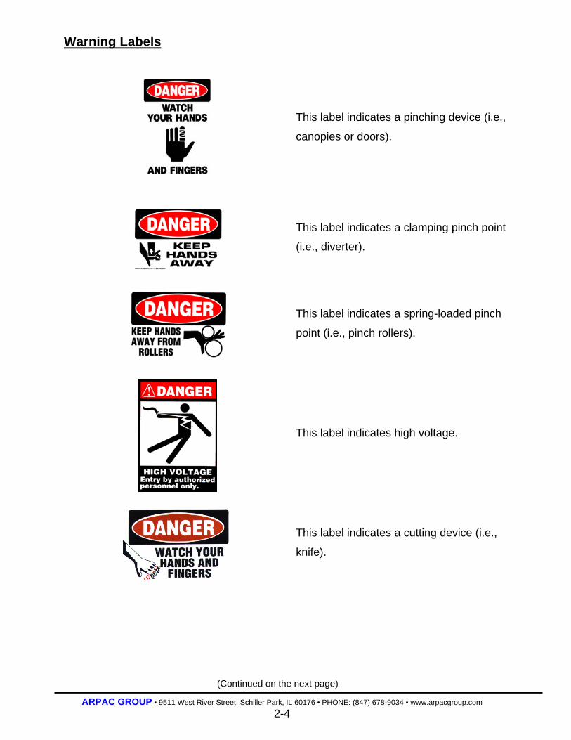
Warning Labels
This label indicates a pinching device (i.e.,
canopies or doors).
This label indicates a clamping pinch point
(i.e., diverter).
This label indicates a spring-loaded pinch
point (i.e., pinch rollers).
This label indicates high voltage.
This label indicates a cutting device (i.e.,
knife).
(Continued on the next page)

ARPAC GROUP • 9511 West River Street, Schiller Park, IL 60176 • PHONE: (847) 678-9034 • www.arpacgroup.com 2-5
Warning Labels
This label indicates unseen energy hazards
(i.e., electrical or pneumatic).
This label indicates the necessity of re-
installing guards and covers after cleaning
or maintenance of the machine.
This label indicates a solid pinch point (i.e.,
gear or sprocket).
This label indicates mechanical moving
parts (i.e., carriage, chains, sprockets and
cylinders).
This label indicates that the machine will
start and stop without warning. The green
indicator light on the machine’s operator
control panel will be illuminated when the
machine is in the cycle mode.

ARPAC GROUP • 9511 West River Street, Schiller Park, IL 60176 • PHONE: (847) 678-9034 • www.arpacgroup.com 2-6
Warning Labels
This label indicates the potential presence
of fork lifts. Personnel should be watchful
while working around this machinery.
This label indicates employees and other
personnel should not be working or located
in this area.

ARPAC GROUP • 9511 West River Street, Schiller Park, IL 60176 • PHONE: (847) 678-9034 • www.arpacgroup.com 3-0
SECTION 3
Mechanical Sub-Assemblies
3-1 Top Sheet Dispenser 3-2 Base and Turntable
3-6 Film Clamp 3-6 Film Wipe Arm
3-7 Tower & Control Cabinet 3-8 Film Saver
3-9 Dancer Arm
3-10 Infeed Powered Conveyor 3-11 Exit Powered Conveyor 3-12 Auxiliary Gravity Conveyor (Optional)
ARPAC GROUP • 9511 West River Street, Schiller Park, IL 60176 • PHONE: (847) 678-9034 • www.arpacgroup.com 3-1
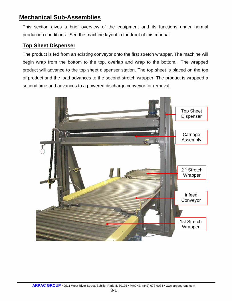
Mechanical Sub-Assemblies This section gives a brief overview of the equipment and its functions under normal
production conditions. See the machine layout in the front of this manual.
Top Sheet Dispenser The product is fed from an existing conveyor onto the first stretch wrapper. The machine will
begin wrap from the bottom to the top, overlap and wrap to the bottom. The wrapped
product will advance to the top sheet dispenser station. The top sheet is placed on the top
of product and the load advances to the second stretch wrapper. The product is wrapped a
second time and advances to a powered discharge conveyor for removal.
Carriage Assembly
Top Sheet Dispenser
Infeed Conveyor
1st Stretch Wrapper
2nd Stretch Wrapper

ARPAC GROUP • 9511 West River Street, Schiller Park, IL 60176 • PHONE: (847) 678-9034 • www.arpacgroup.com 3-2
Base and Turntable The base holds the turntable, film wipe arm, cutting device and tower. It is made of
custom formed steel channel with steel tube reinforcement. All joints are of welded steel
construction. The turntable, film guide and tower mount to the base, while the wipe arm
and cutting device are mounted to the turntable.
The machine starts with the turntable in the home position, the film clamp clamped on the
film (1-10” of film), the film saver in the start position and the film wipe device in its home
position. The machine is placed in the cycle mode.
(Continued on the next page)
Tower
Film Carriage
Turntable
Film Wipe Arm
Product Detect Photo Eye
Clamping Device
ARPAC GROUP • 9511 West River Street, Schiller Park, IL 60176 • PHONE: (847) 678-9034 • www.arpacgroup.com 3-3
Base and Turntable The infeed conveyor transfers a pallet to the turntable conveyor which stops the pallet
centered to it. Photo eyes located on the conveyors before and after the turntable
conveyor signal the PLC in the event the pallet does not stop in the proper position and
the machine will not cycle. The turntable conveyor receives a pallet from the infeed
conveyor. A product detect photo eye detects the pallet and starts a timer. When the
timer times out it is assumed that the pallet is centered to the turntable and the turntable
conveyor drive stops.
The turntable starts rotating only after the turntable conveyor has stopped, the safety
photo eyes between the transition conveyors and the powered conveyors are clear of
product and the safety switch located at the entrance of the turntable conveyor is not
triggered. The turntable rotates until the preset wrap pattern is completed. The operator
can change the wrap pattern using the operator interface controls, see section 5.
Near the end of the wrap cycle with the film saver moving in the downward direction, the
film saver is detected by the clamp open proximity sensor which stops the vertical
movement of the film saver. The turntable passes its home position starting the delay to
open film clamp timer (very short timer). When the timer times out the film clamp opens,
the film saver immediately lowers to its lower most position (capturing the film tail) and the
turntable continues rotating until the set number of bottom wraps (dictated by the wrap
counter) is completed. Just before the final wrap the turntable rotates one complete
revolution at the slow speed allowing a contractor installed label machine to apply a label
to each side of the pallet. During the final wrap the turntable slows its wrap speed and
stops at its home position. At this time the film wipe arm moves 90° pressing the film
against the pallet, the film clamp closes on the film (1-10” of film) and power is applied to
the hot wire, which cuts the film. The film wipe arm moves forward, wiping the film against
the wrapped pallet and returns to its home position. The turntable conveyor turns on and
transfers the wrapped pallet onto the exit conveyor. After the pallet exits the turntable a
timer is started and is reset when the next pallet from the infeed conveyor enters the
turntable and the cycle continues. In the event the timer is allowed to time out before the
next pallet is transferred to the turntable the turntable conveyor will stop in the idle mode.
As soon as the photo eyes detect a product transferring onto the turntable the turntable
conveyor automatically restarts and the cycle continues.
(Continued on the next page)
ARPAC GROUP • 9511 West River Street, Schiller Park, IL 60176 • PHONE: (847) 678-9034 • www.arpacgroup.com 3-4
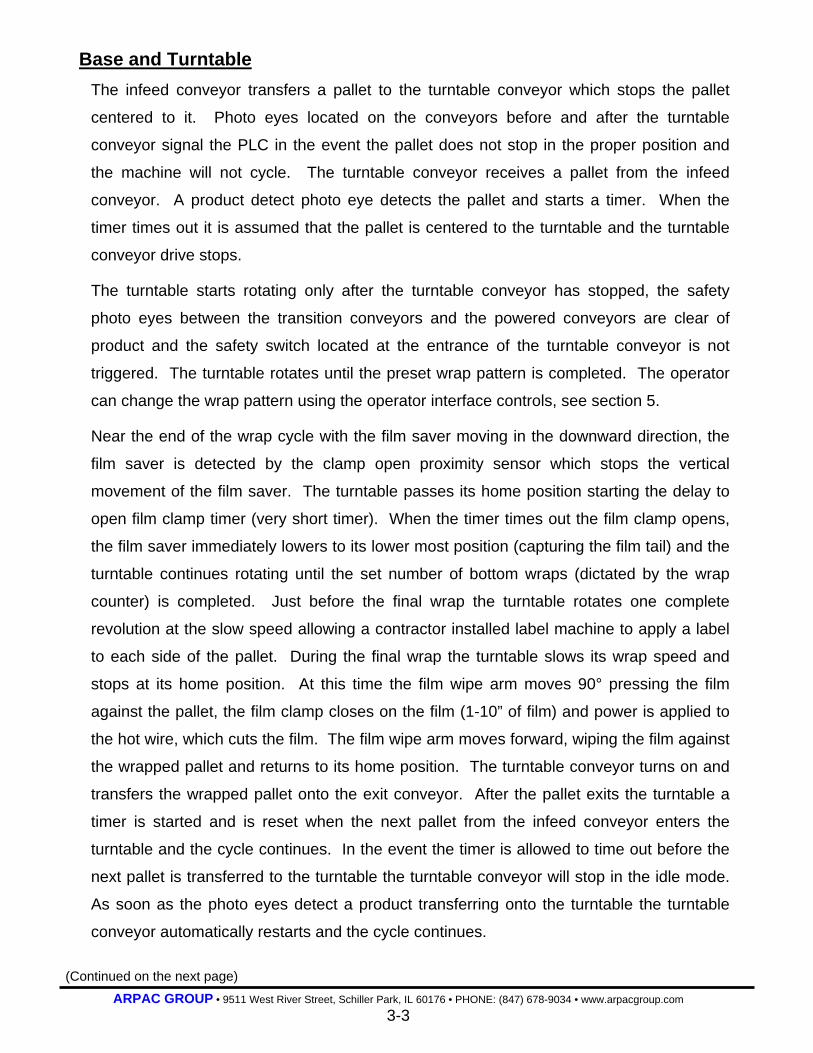
Base and Turntable A motor mounted to the base, as well as electrical and pneumatic connections are located
under the turntable. The motor rotates the turntable, while the electrical and pneumatic
lines power the turntable conveyor motor and film clamp, both mounted to the turntable.
The set of commutator rings and brushes used to transfer power to the turntable motor
should be maintained regularly. See Section 7 Maintenance and Section 12 Vendor
Information for details.
The photo eye that detects the product on the turntable is located on the tower. The
infeed conveyor is programmed not to transfer a pallet onto the turntable conveyor while a
pallet is currently positioned there. Likewise the turntable conveyor is programmed not to
transfer a pallet onto the exit conveyor while a pallet is currently positioned there. If at any
time during the wrap cycle the safety photo eyes become blocked or the safety switch is
triggered the machine cycle will stop, the red stack light will flash and an error message
will be displayed on the operator interface.
The safety switch located at the side of the entrance of the turntable detects the pallet or
something positioned outside the acceptable pallet placement area on the turntable during
wrapping of the pallet. When the switch is triggered it indicates the pallet or something on
the pallet is overhanging the acceptable wrapping parameter of the turntable.
Commutator Rings and Brushes
Turntable Drive Motor
Turntable Drive Chain
Casters
(Continued on the next page)

ARPAC GROUP • 9511 West River Street, Schiller Park, IL 60176 • PHONE: (847) 678-9034 • www.arpacgroup.com 3-5
Base and Turntable
Anything outside this parameter will interfere with the rotation of the turntable possibly
causing damage to the machine and or the product. Therefore, the safety switch will stop
the machine cycle and signal the situation through the stack light and the operator
interface.
A proximity sensor located at the base of the turntable, is used to signal the home position
of the turntable. The speed of the turntable is controlled by a potentiometer dial on the
operator interface.
NOTE: This machine is capable of operating in multiple modes and therefore depending on the mode of operation it will operate slightly different.
ARPAC GROUP • 9511 West River Street, Schiller Park, IL 60176 • PHONE: (847) 678-9034 • www.arpacgroup.com 3-6
Base and Turntable
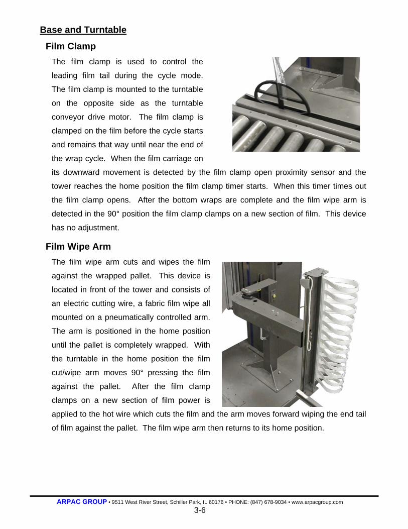
Film Clamp The film clamp is used to control the
leading film tail during the cycle mode.
The film clamp is mounted to the turntable
on the opposite side as the turntable
conveyor drive motor. The film clamp is
clamped on the film before the cycle starts
and remains that way until near the end of
the wrap cycle. When the film carriage on
its downward movement is detected by the film clamp open proximity sensor and the
tower reaches the home position the film clamp timer starts. When this timer times out
the film clamp opens. After the bottom wraps are complete and the film wipe arm is
detected in the 90° position the film clamp clamps on a new section of film. This device
has no adjustment.
Film Wipe Arm The film wipe arm cuts and wipes the film
against the wrapped pallet. This device is
located in front of the tower and consists of
an electric cutting wire, a fabric film wipe all
mounted on a pneumatically controlled arm.
The arm is positioned in the home position
until the pallet is completely wrapped. With
the turntable in the home position the film
cut/wipe arm moves 90° pressing the film
against the pallet. After the film clamp
clamps on a new section of film power is
applied to the hot wire which cuts the film and the arm moves forward wiping the end tail
of film against the pallet. The film wipe arm then returns to its home position.

ARPAC GROUP • 9511 West River Street, Schiller Park, IL 60176 • PHONE: (847) 678-9034 • www.arpacgroup.com 3-7
Tower & Control Cabinet
Tower The tower assembly is located opposite the
turntable on the base of the machine. It supports
the film carriage lift motor, the machine’s
controller and the electrical control board. The
function of the tower is to contain the electrical
controls and provide support for the movement of
the film carriage.
Control Cabinet The control cabinet contains the PLC, the operator
interface, the controls for the machine and most of
the electrical circuitry. It is located near the
machine outside the safety fence.
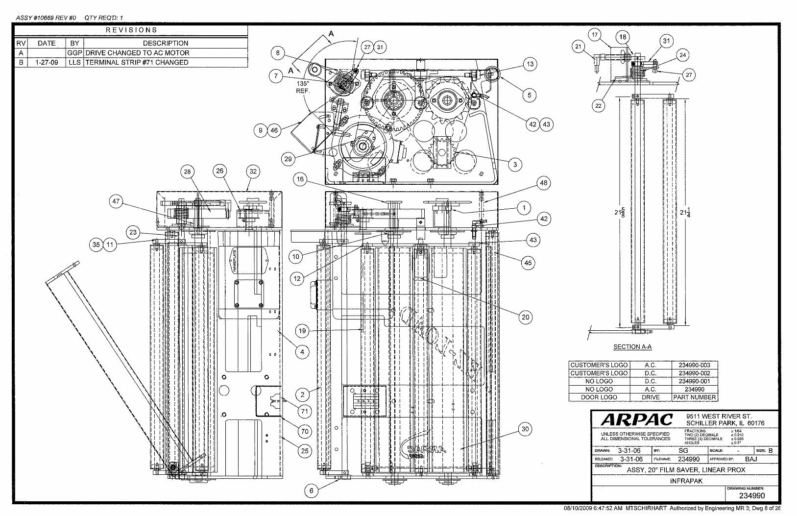
Film Saver
Tower
Product Detect PE
Wipe Arm

ARPAC GROUP • 9511 West River Street, Schiller Park, IL 60176 • PHONE: (847) 678-9034 • www.arpacgroup.com 3-8
Film Saver The film saver is the mechanical assembly used to hold the film roll and distribute film to
the product as the turntable rotates. This assembly consists of a film holder, dancer bar,
film feed rollers and film guide rollers. The film saver is mounted to the film carriage
bracket inside the tower.
The film carriage drive controls the vertical movement of the film saver. Depending on the
wrap pattern selected, the film carriage ascends and descends the tower as the turntable
rotates. The product load height photo eye is used to detect the top of the product. This
photo eye signals the machine to start its over wrap cycle (controlled by the over wrap
potentiometer). This allows the operator to wrap a portion of the top of the product.
Film Dancer Bar
Film Guide Rollers
Film Holder
Film Saver Drive (under cover)
Load Height PE

ARPAC GROUP • 9511 West River Street, Schiller Park, IL 60176 • PHONE: (847) 678-9034 • www.arpacgroup.com 3-9
Film Saver
Dancer Arm The dancer arm assembly is made up of a series of film guide rollers, a stationary arm
and a spring-loaded pivoting arm. The purpose of the dancer arm is to provide film to
the machine that is under constant and consistent tension.
The dancer arm is connected to a micro-switch and direct-drive
potentiometer. The turntable rotates and pulls the film. When the
film is pulled the spring-loaded dancer arm rotates this closes the
micro-switch and rotates the potentiometer. The micro-switch
supplies power to the film saver motor while the potentiometer
regulates the amount of power.
Demand for film is placed on the film feed system as the turntable
rotates causing the micro-switch to close and the potentiometer to
rotate slightly. This applies a low amount of power to the film feed
motor which drives the film feed rollers at a low rate. Additional film
is required when the product corners are wrapped causing additional
demand. This causes the potentiometer to rotate more applying
more power to the film feed drive motor, increasing the speed of the
film feed rollers. This action is called corner compensation.
When the demand diminishes the dancer arm moves backward
adjusting the potentiometer along with it. This slows down the film
feed motor. When demand stops altogether the micro-switch opens
removing all power from the motor. Film Guide Rollers
Film Dancer Arm
Film Feed POT
Dancer Pivot Shaft
Dancer Micro-switch
Under Film Saver Cover

ARPAC GROUP • 9511 West River Street, Schiller Park, IL 60176 • PHONE: (847) 678-9034 • www.arpacgroup.com 3-10
Infeed Powered Conveyor The infeed powered conveyor is an independently clutched driven roller conveyor located
at the entrance of the turntable conveyor. The purpose of this conveyor is to transfer
product to the turntable conveyor.
With the machine in the cycle mode, product transfers onto this conveyor by the
customer’s conveyor. The clutch that drives the rollers is not activated at this time
allowing the rollers to turn freely as a pallet is transferred onto the conveyor. The product
detect photo eye detects the pallet and signals the PLC that a product is present and turns
on the clutch which drives the rollers that transfer the pallet onto the turntable conveyor.
When the pallet clears the load before wrapper safety photo eye the clutch drive turns off.
If a product is currently staged on the turntable conveyor, or a product is not detected on
the infeed conveyor or the lift truck is detected at the infeed conveyor the conveyor drive
will not turn on.
The load before wrapper safety photo eye is located at the point where this conveyor
meets the transition conveyor. The turntable will not rotate when this photo eye is
blocked.
NOTE: Any time the forklift truck detect P.E. detects a forklift truck or anything else the conveyor will not be allowed to start. In the event the conveyor is running and this P.E. detects anything the conveyor will immediately stop and an error message will be displayed on the operator interface indicating this.
Load Before Wrapper Safety P.E.
Product Present P.E.
Drive Rollers
Forklift Truck Detect P. E.

ARPAC GROUP • 9511 West River Street, Schiller Park, IL 60176 • PHONE: (847) 678-9034 • www.arpacgroup.com 3-11
Exit Powered Conveyor The exit powered conveyor is an independently driven roller conveyor located after the exit
of the turntable conveyor. The purpose of this conveyor is to transfer product from the
turntable conveyor to the auxiliary gravity conveyor.
1. Load Overrun Stop Position (safety) P.E.
2. Load Exiting Wrap Conveyor (safety) P.E.
3. Load On Exit (90°) Conveyor P.E.
4. Permission To Discharge From Exit Conveyor (mount on customer’s conveyor) P.E.
With the machine in the cycle mode the turntable completes the wrapping of a pallet and
stops in the discharge position. The PLC checks the downstream conveyor in this case
the exit conveyor. When clear the PLC turns on the turntable and exit conveyors
transferring the wrapped pallet across the transition conveyor and onto the exit conveyor.
The pallet continues and blocks the (load on 90° exit conveyor) p.e. The PLC checks the
(permission to discharge from exit conveyor) p.e. located on the customer’s downstream
conveyor. When clear the PLC activates the exit conveyor transferring the pallet onto the
customer’s conveyor. The exit conveyor then stops completing the cycle.
Product Flow
3
2
4
1
ARPAC GROUP • 9511 West River Street, Schiller Park, IL 60176 • PHONE: (847) 678-9034 • www.arpacgroup.com 3-12
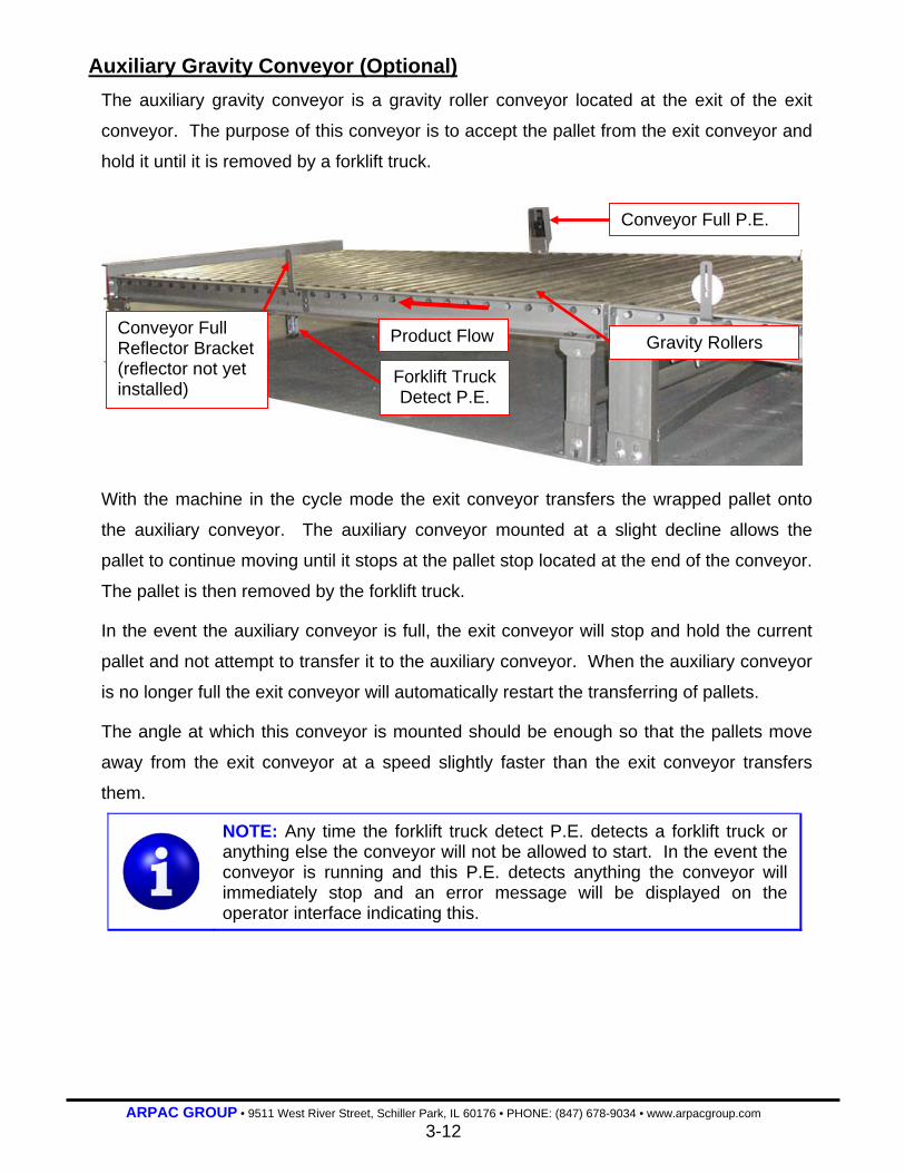
Auxiliary Gravity Conveyor (Optional) The auxiliary gravity conveyor is a gravity roller conveyor located at the exit of the exit
conveyor. The purpose of this conveyor is to accept the pallet from the exit conveyor and
hold it until it is removed by a forklift truck.
With the machine in the cycle mode the exit conveyor transfers the wrapped pallet onto
the auxiliary conveyor. The auxiliary conveyor mounted at a slight decline allows the
pallet to continue moving until it stops at the pallet stop located at the end of the conveyor.
The pallet is then removed by the forklift truck.
In the event the auxiliary conveyor is full, the exit conveyor will stop and hold the current
pallet and not attempt to transfer it to the auxiliary conveyor. When the auxiliary conveyor
is no longer full the exit conveyor will automatically restart the transferring of pallets.
The angle at which this conveyor is mounted should be enough so that the pallets move
away from the exit conveyor at a speed slightly faster than the exit conveyor transfers
them.
NOTE: Any time the forklift truck detect P.E. detects a forklift truck or anything else the conveyor will not be allowed to start. In the event the conveyor is running and this P.E. detects anything the conveyor will immediately stop and an error message will be displayed on the operator interface indicating this.
Gravity Rollers Product Flow
Conveyor Full P.E.
Forklift Truck Detect P.E.
Conveyor Full Reflector Bracket (reflector not yet installed)

ARPAC GROUP • 9511 West River Street, Schiller Park, IL 60176 • PHONE: (847) 678-9034 • www.arpacgroup.com 4-0
SECTION 4
Operator Controls
4-1 Main Power Disconnect Switch 4-1 Master Air Supply Regulator 4-1 Emergency Stop Push-Pull Button 4-2 Power On Push Button 4-2 Cycle Stop/Reset Push Button 4-2 Cycle Start/Restart Push Button 4-3 Rewrap Push Button 4-3 Turntable Home Push Button 4-3 Film Clamp Open/Close Push Button 4-4 Turntable Jog Selector Switch 4-4 Carriage Jog Selector Switch 4-4 Cycle Select A B C Selector Switch 4-5 Infeed Conveyor Jog Selector Switch 4-5 Wrap Conveyor Jog Selector Switch 4-5 Exit Conveyor Jog Selector Switch 4-6 Turntable Speed Potentiometer 4-6 Overwrap Potentiometer 4-6 Carriage Raise Speed Potentiometer 4-7 Load Compression Potentiometer 4-7 Carriage Lower Speed Potentiometer 4-7 TSD Up Down Selector Switch 4-8 Manual Sheet Cycle Push Button 4-8 By-Pass Selector Switch 4-8 Operator Interface 4-9 Base Wrap Counter and Top Wrap Counter 4-9 Adjustment Handles 4-9 Swift Change Film Mandrel 4-10 Alarm Horn (optional) 4-10 Stack Light 4-10 Air Flow Control Valves
ARPAC GROUP • 9511 West River Street, Schiller Park, IL 60176 • PHONE: (847) 678-9034 • www.arpacgroup.com 4-1
Operator Controls
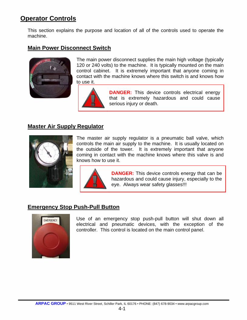
This section explains the purpose and location of all of the controls used to operate the machine. Main Power Disconnect Switch
The main power disconnect supplies the main high voltage (typically 120 or 240 volts) to the machine. It is typically mounted on the main control cabinet. It is extremely important that anyone coming in contact with the machine knows where this switch is and knows how to use it.
DANGER: This device controls electrical energy that is extremely hazardous and could cause serious injury or death.
Master Air Supply Regulator
The master air supply regulator is a pneumatic ball valve, which controls the main air supply to the machine. It is usually located on the outside of the tower. It is extremely important that anyone coming in contact with the machine knows where this valve is and knows how to use it.
DANGER: This device controls energy that can be hazardous and could cause injury, especially to the eye. Always wear safety glasses!!!
Emergency Stop Push-Pull Button
Use of an emergency stop push-pull button will shut down all electrical and pneumatic devices, with the exception of the controller. This control is located on the main control panel.

ARPAC GROUP • 9511 West River Street, Schiller Park, IL 60176 • PHONE: (847) 678-9034 • www.arpacgroup.com 4-2
Operator Controls Power On Push Button
The power on push button supplies power to the main drive motor and the master air supply dump solenoid valve. This control is located on the main control panel. The white indicator light will illuminate when this push button has been activated.
Cycle Stop Push Button
The cycle stop push button interrupts the wrap cycle and resets the wrap counters. The red indicator light will illuminate when this push button has been activated or when there is a fault condition. To reset, press button twice.This control is located on the main control panel.
Cycle Start Push Button
The cycle start push button starts the normal cycle of the machine and restarts the machine after the operator applies the top sheet of film. The green indicator light will illuminate when this push button has been activated. Operators should be aware that the machine is in cycle mode and may be sitting idle until product enters the wrap zone. When using a two machine configuration both buttons need to be pushed so they are in the cycle start mode. This control is located on the main control panel.
DANGER: Use of this push button does not de-energize the machine or relieve pneumatic pressure.
DANGER: To avoid personnel injury, always check around the machine before pressing this push button. Keep clothing and body parts clear of all machinery.
ARPAC GROUP • 9511 West River Street, Schiller Park, IL 60176 • PHONE: (847) 678-9034 • www.arpacgroup.com 4-3
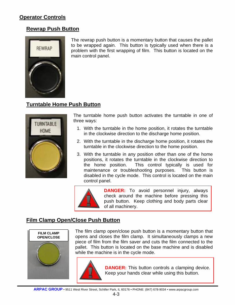
Operator Controls Rewrap Push Button
The rewrap push button is a momentary button that causes the pallet to be wrapped again. This button is typically used when there is a problem with the first wrapping of film. This button is located on the main control panel.
Turntable Home Push Button The turntable home push button activates the turntable in one of three ways:
1. With the turntable in the home position, it rotates the turntable in the clockwise direction to the discharge home position.
2. With the turntable in the discharge home position, it rotates the turntable in the clockwise direction to the home position.
3. With the turntable in any position other than one of the home positions, it rotates the turntable in the clockwise direction to the home position. This control typically is used for maintenance or troubleshooting purposes. This button is disabled in the cycle mode. This control is located on the main control panel.
DANGER: To avoid personnel injury, always check around the machine before pressing this push button. Keep clothing and body parts clear of all machinery.
Film Clamp Open/Close Push Button
The film clamp open/close push button is a momentary button that opens and closes the film clamp. It simultaneously clamps a new piece of film from the film saver and cuts the film connected to the pallet. This button is located on the base machine and is disabled while the machine is in the cycle mode.
DANGER: This button controls a clamping device. Keep your hands clear while using this button.
FILM CLAMP OPEN/CLOSE

ARPAC GROUP • 9511 West River Street, Schiller Park, IL 60176 • PHONE: (847) 678-9034 • www.arpacgroup.com 4-4
Operator Controls Turntable Jog Selector Switch
The turntable jog selector switch allows the operator to manually jog or rotate the turntable in the direction indicated for as long as the switch is held. This control is located on the main control panel and is disabled during the cycle mode.
Carriage Jog Selector Switch
The carriage jog selector switch allows the operator to manually control the position of the carriage. This control typically is used for maintenance or troubleshooting purposes. This switch is disabled when the machine is in the cycle mode. This control is located on the main control panel.
• Carriage Down: Lowers the carriage while the machine is out of cycle.
• Carriage Up: Raises the carriage while the machine is out of cycle.
Cycle Mode Select A B C Selector Switch
The cycle mode selector switch allows the operator to select the specific wrap pattern. This control is located on the main control panel.
• Pattern A: Carriage wraps base first, then the top and returns to the bottom to end the wrap cycle.
• Pattern B: Carriage wraps top first, then the base and then ends the wrap cycle.
• Pattern C: Carriage wraps base first, then the top and then ends the wrap cycle. In some cases, this option is disabled.
This button is disabled in the cycle mode. This control is located on the main control panel.
Operator Controls
DANGER: To avoid personnel injury, always check around the machine before using this selector switch. Keep clothing and body parts clear of all machinery.
CYCLE MODE A B C
ARPAC GROUP • 9511 West River Street, Schiller Park, IL 60176 • PHONE: (847) 678-9034 • www.arpacgroup.com 4-5
Infeed Conveyor Jog Selector Switch
The infeed conveyor jog selector switch allows the operator to manually jog the infeed conveyor in the direction indicated for as long as the switch is held. This control is located on the main control panel.
Wrap Conveyor Jog Selector Switch
The wrap conveyor jog selector switch allows the operator to manually jog the wrap or turntable conveyor in the direction indicated for as long as the switch is held. This control is located on the main control panel.
Exit Conveyor Jog Selector Switch
The exit conveyor jog selector switch allows the operator to manually jog the exit in the direction indicated for as long as the switch is held. This control is located on the main control panel.
ARPAC GROUP • 9511 West River Street, Schiller Park, IL 60176 • PHONE: (847) 678-9034 • www.arpacgroup.com 4-6
Operator Controls Turntable Speed Potentiometer
The turntable speed potentiometer adjusts the speed of the rotation of the turntable during the wrap cycle. Adjust in small increments while the turntable is rotating. This control is located on the main control panel.
DANGER: To avoid personnel injury, always check around the machine before using this control. Keep clothing and body parts clear of all machinery.
Overwrap Potentiometer The overwrap potentiometer adjusts the film travel above the pallet and disables the photo eye when the knob pointer is within the shaded area. Adjust in small increments while in the cycle mode. Always observe the next cycle after adjusting. This control is located on the main control panel.
DANGER: To avoid personnel injury, always check around the machine before using this control. Keep clothing and body parts clear of all machinery.
Carriage Raising Speed Potentiometer
The carriage raise speed potentiometers adjust the upward speed of the film carriage while the machine is in the wrap cycle. Adjust in small increments while the carriage is moving in the upward direction. This control is located on the main control panel.
DANGER: To avoid personnel injury, always check around the machine before using this control. Keep clothing and body parts clear of all machinery.

ARPAC GROUP • 9511 West River Street, Schiller Park, IL 60176 • PHONE: (847) 678-9034 • www.arpacgroup.com 4-7
Operator Controls Load Compression Potentiometer
The load compression potentiometer adjusts the amount of stretch between the film saver and the load. Adjust in small increments while the machine is in the cycle mode. This control is located on the main control panel.
Carriage Lower Speed Potentiometer
The carriage lower speed potentiometers adjust the downward speed of the film carriage while the machine is in the wrap cycle. Adjust in small increments while the carriage is moving in the downward direction. This control is located on the main control panel.
DANGER: To avoid personnel injury, always check around the machine before using this control. Keep clothing and body parts clear of all machinery.
TSD Up Down Selector Switch
The TSD (Top Sheet Dispenser) selector switch is a momentary switch that causes the TSD carriage to move up and down depending on its selected position. This switch is disabled in the cycle mode. This switch is located on the side of the dispenser frame.
DANGER: To avoid personnel injury, always check around the machine before using this control. Keep clothing and body parts clear of all machinery.

ARPAC GROUP • 9511 West River Street, Schiller Park, IL 60176 • PHONE: (847) 678-9034 • www.arpacgroup.com 4-8
Operator Controls
Manual Sheet Cycle Push Button
The manual sheet cycle button dispenses the set amount of top film. This is typically used when threading a new film roll or pre-fitting after clearing a jam.
By Pass Selector Switch
The by pass on off selector switch is used only when you want to move product through to the exit conveyor without wrapping it. Select the on position to do so.
Operator Interface
The operator uses this interface to communicate with the PLC in the machine. The screen is used to indicate the machines current mode of operation and any problem the machine may encounter, as well as to help the operator make any necessary changes or adjustments to timers in the program.
NOTE: There is a password lockout to change timers.
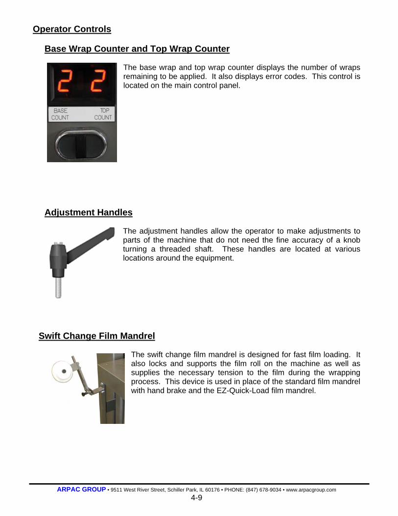
ARPAC GROUP • 9511 West River Street, Schiller Park, IL 60176 • PHONE: (847) 678-9034 • www.arpacgroup.com 4-9
Operator Controls
Base Wrap Counter and Top Wrap Counter
The base wrap and top wrap counter displays the number of wraps remaining to be applied. It also displays error codes. This control is located on the main control panel.
Adjustment Handles
The adjustment handles allow the operator to make adjustments to parts of the machine that do not need the fine accuracy of a knob turning a threaded shaft. These handles are located at various locations around the equipment.
Swift Change Film Mandrel
The swift change film mandrel is designed for fast film loading. It also locks and supports the film roll on the machine as well as supplies the necessary tension to the film during the wrapping process. This device is used in place of the standard film mandrel with hand brake and the EZ-Quick-Load film mandrel.
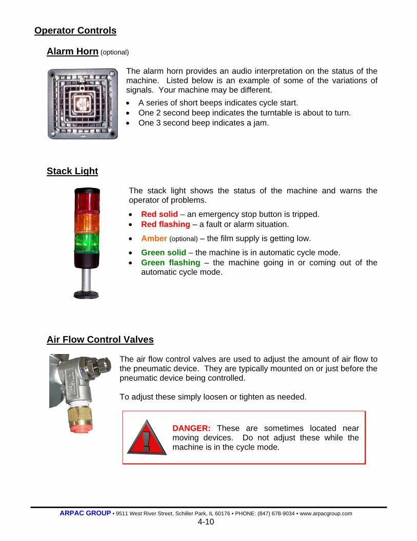
ARPAC GROUP • 9511 West River Street, Schiller Park, IL 60176 • PHONE: (847) 678-9034 • www.arpacgroup.com 4-10
Operator Controls Alarm Horn (optional)
The alarm horn provides an audio interpretation on the status of the machine. Listed below is an example of some of the variations of signals. Your machine may be different. • A series of short beeps indicates cycle start. • One 2 second beep indicates the turntable is about to turn. • One 3 second beep indicates a jam.
Stack Light
The stack light shows the status of the machine and warns the operator of problems.
• Red solid – an emergency stop button is tripped. • Red flashing – a fault or alarm situation.
• Amber (optional) – the film supply is getting low.
• Green solid – the machine is in automatic cycle mode. • Green flashing – the machine going in or coming out of the
automatic cycle mode.
Air Flow Control Valves
The air flow control valves are used to adjust the amount of air flow to the pneumatic device. They are typically mounted on or just before the pneumatic device being controlled. To adjust these simply loosen or tighten as needed.
DANGER: These are sometimes located near moving devices. Do not adjust these while the machine is in the cycle mode.

ARPAC GROUP • 9511 West River Street, Schiller Park, IL 60176 • PHONE: (847) 678-9034 • www.arpacgroup.com 5-0
SECTION 5
Operating Procedures 5-1 Initial Startup 5-2 Quick Startup 5-3 Emergency Shutdown 5-3 Short-Term Shutdown 5-3 Long-Term Shutdown 5-4 Film Roll Installation 5-5 Film Threading
5-5 Film Threading Diagram
5-7 Product Setup Procedures 5-9 Product Setup Chart
5-10 Operator Interface 5-10 Navigating the Screens 5-11 Selecting Product 5-12 Viewing, Changing and Saving Parameters 5-14 Messages 5-14 Timers 5-15 Machine Counters (optional) 5-16 Maintenance 5-17 Main Menu 5-18 Screen Brightness
5-18 Wrap Pattern Descriptions (Optional) 5-19 A Wrap Pattern (Not Applicable) 5-19 B Wrap Pattern 5-19 C Wrap Pattern (Bypass Mode)

ARPAC GROUP • 9511 West River Street, Schiller Park, IL 60176 • PHONE: (847) 678-9034 • www.arpacgroup.com 5-1
Operating Procedures
This section describes how to operate the machine. This includes startups, shutdowns, film
roll installation, and film threading and sealing. In addition, procedures are provided for
various machine and changeover adjustments.
Initial Startup Applies to the first time the machine is run and the initial start up of each shift.
Pre-Start Inspection 1. Make sure the machine and the area around the machine is clear of all products and
any other items not directly related to the normal operation of the machine.
2. Check the pneumatic lubricator, and regulator. Fill or empty accordingly.
3. Inspect the film carriage, film saver and conveyors for debris. 4. Ensure all persons in the area of the machine are aware the machine is about to start.
Startup 1. Place the main power disconnect to the on position.
DANGER: Stop the operation if you cannot adjust the regulator to read at least 80 psi. Do not try to run the machine. See your supervisor immediately.
2. Open the master air supply regulator valve.
3. Pull out the emergency stop push-pull button.
4. Press the power on push button.
5. Load and thread the film. See film roll installation and film threading.
6. Press the cycle stop/reset push button to reset any faults.
7. Press the cycle start/restart push button. A pallet will enter the infeed conveyor and
stop just before the transition conveyor.
DANGER: Be aware the machine is in the cycle mode. The green indicator light will turn on and the machine will sit idle until the (detect load before infeed conveyor) p.e. detects product.
8. Place a sheet of film on top of the pallet and press the cycle start/restart push
button.
ARPAC GROUP • 9511 West River Street, Schiller Park, IL 60176 • PHONE: (847) 678-9034 • www.arpacgroup.com 5-2
Quick Startup Applies to when the machine is started at the beginning of a shift.
DANGER: Be aware while working with the machine during this time. There are many possibly hazardous moving parts, including chains and sprockets.
Pre-Start Inspection 1. Make sure the machine and the area around the machine is clear of all products and
any other items not directly related to the normal operation of the machine.
2. Check the pneumatic lubricator, and regulator. Fill or empty accordingly.
3. Inspect the film carriage, film saver and conveyors for debris.
4. Ensure all persons in the area of the machine are aware the machine is about to start.
Startup
DANGER: Stop the operation if you cannot adjust the regulator to read at least 80 psi. Do not try to run the machine. See your supervisor immediately.
1. Check the master air supply regulator valves.
2. Pull out the emergency stop push-pull button.
3. Press the power on push button.
4. Press the cycle start/restart push button. A pallet will enter the infeed conveyor and
stop just before the transition conveyor.
DANGER: Be aware the machine is in the cycle mode. The green indicator light will turn on and the machine will sit idle until the (detect load before infeed conveyor) p.e. detects product.
5. Place a sheet of film on top of the pallet and press the cycle start/restart push
button.
ARPAC GROUP • 9511 West River Street, Schiller Park, IL 60176 • PHONE: (847) 678-9034 • www.arpacgroup.com 5-3
Emergency Shutdown Applies to times when the machine needs to be shut down immediately. This includes all
times when personnel or the equipment are in danger of being damaged.
DANGER: When the emergency stop push-pull button is pressed the machine will stop immediately.
1. Press any emergency stop push-pull button.
2. Take care of the emergency situation.
Short-Term Shutdown Applies to times when the machine is not shut down completely, such as for a break or to
perform certain adjustments.
1. Stop the flow of product to this machine.
2. After the last product has cleared the wrap zone, press the cycle stop/reset push
button.
Long-Term Shutdown Applies to times when the machine will be shut down completely, such as overnight,
weekends or to perform changeover procedures.
1. Stop the flow of product to this machine.
2. After the last product has been removed, press the cycle stop/reset push button.
3. Press the emergency stop push-pull button.
4. Close the master air supply regulator valve.

ARPAC GROUP • 9511 West River Street, Schiller Park, IL 60176 • PHONE: (847) 678-9034 • www.arpacgroup.com 5-4
Film Roll Installation
DANGER: All personnel must remain clear of the control panel while film is being loaded. The film feed safety switch located in the film saver is used to prevent accidental activation of the powered rollers during film loading and threading.
Swift Change Film Mandrel 1. Pull the knob to release the top of film holder and swing it
back to release the film roll.
2. Place the roll of film on the film roll mandrel so it unwinds
in a clockwise direction and the film core is seated over
the bottom thrust bearing.
3. Swing the film holder back to capture the top of the film
roll, pull knob, push down and lock into position.
4. Unroll enough film to thread through the film saver
(approximately 4 feet).

ARPAC GROUP • 9511 West River Street, Schiller Park, IL 60176 • PHONE: (847) 678-9034 • www.arpacgroup.com 5-5
Film Threading
DANGER: All personnel must remain clear of the control panel while film is being loaded. The film feed switch is used to prevent accidental activation of the powered rollers during loading and threading.
1. Open the film saver door and thread the film using the Film-Threading Diagram below.
This diagram is also located on the machine on or near the film saver.
2. Pull enough film to reach the film clamp making sure the film is wrinkle free through the
film saver rollers.
3. Close and latch the film saver door. The machine will not cycle when the film saver
door is open.
4. Hold the film above the center of the open film clamp. In the event the clamp is not
open, keeping your hands clear of the film clamp, press the clamp open/close push
button and the clamp will open.
5. Keeping your hands clear of the film clamp press the clamp open/close push button.
The film clamp will close on the film completing the film threading procedure.

ARPAC GROUP • 9511 West River Street, Schiller Park, IL 60176 • PHONE: (847) 678-9034 • www.arpacgroup.com 5-6
Product Setup Procedures The following procedure should be performed when setting up for a new product.
1. Place the cycle select selector switch to the desired wrap pattern.
2. Enter the desired number of wraps for both the top and base.
3. Turn the load compression potentiometer to ZERO.
4. Turn the carriage raise and lower speed potentiometers to FIVE.
5. Turn the overwrap potentiometer to ONE.
6. Manually center a product on the wrap conveyor.
7. Make sure the film is threaded properly.
8. Press the manual/auto push button.
NOTE: Allow the machine to complete cut and tie the film before continuing with the setup.
9. Adjust the load compression and carriage speed settings.
Wrap Pattern A: Not Applicable on This Machine • During the base wrap cycle turn the load compression potentiometer clockwise until
the desired load compression is achieved.
• During the film carriage ascent, adjust the carriage raise speed potentiometer to
obtain the desired amount of film overlap. The carriage will ascend until the photo eye
is unblocked at the top of the load and will then apply the top wraps.
• During the film carriage descent, adjust the carriage lower speed potentiometer to
obtain the desired amount of film overlap.
(Continued on the next page)

ARPAC GROUP • 9511 West River Street, Schiller Park, IL 60176 • PHONE: (847) 678-9034 • www.arpacgroup.com 5-7
Product Setup Procedures Wrap Pattern B:
• During the film carriage ascent, adjust the carriage raise speed potentiometer to
obtain the desired amount of film overlap. The carriage will ascend until the photo eye
is unblocked at the top of the load and will then apply the top wraps.
• During the top wrap cycle turn the load compression potentiometer clockwise until
the desired load compression is achieved.
• During the film carriage descent, adjust the carriage lower speed potentiometer to
obtain the desired amount of film overlap.
10. Repeat Steps 8 and 9 as needed.
NOTE: The overwrap adjustment should be performed after the carriage speed is set. If this adjustment is made before the carriage speed setting the overwrap adjustment will most likely need to be readjusted.
11. Turn the overwrap potentiometer to TWO.
12. Press the manual/auto push button.
13. Observe the overwrap and adjust the overwrap setting.
• Increase the setting to increase the amount of film that is wrapped above the top edge
of the product.
• Decrease the setting to decrease the amount of film that is wrapped above the top
edge of the product.
14. Repeat Steps 12 and 13 as needed.
Wrap Pattern C: Bypass Mode
The turntable conveyor operates as a transfer conveyor in this mode. The rest of the
machine does not function.
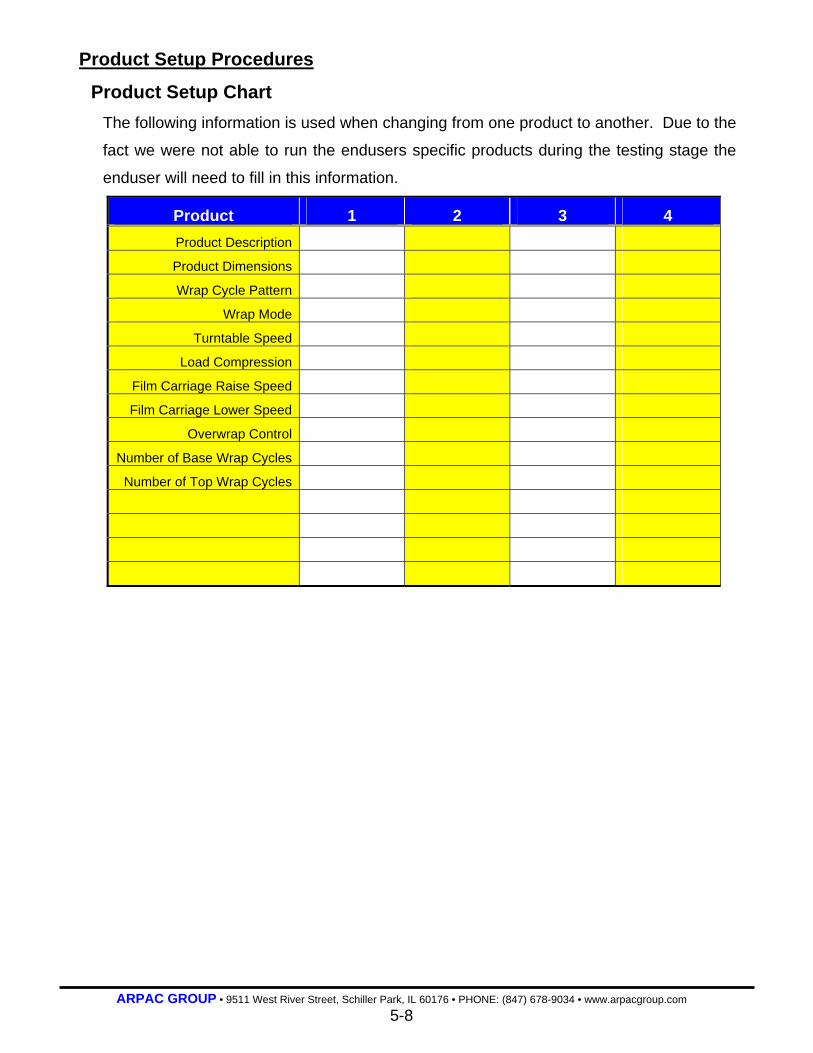
ARPAC GROUP • 9511 West River Street, Schiller Park, IL 60176 • PHONE: (847) 678-9034 • www.arpacgroup.com 5-8
Product Setup Procedures
Product Setup Chart The following information is used when changing from one product to another. Due to the
fact we were not able to run the endusers specific products during the testing stage the
enduser will need to fill in this information.
Product 1 2 3 4 Product Description
Product Dimensions
Wrap Cycle Pattern
Wrap Mode
Turntable Speed
Load Compression
Film Carriage Raise Speed
Film Carriage Lower Speed
Overwrap Control
Number of Base Wrap Cycles
Number of Top Wrap Cycles

ARPAC GROUP • 9511 West River Street, Schiller Park, IL 60176 • PHONE: (847) 678-9034 • www.arpacgroup.com 5-9
Operator Interface
The operator interface displays information about the current status of the machine and
allows operators to changes timers, counters, conveyor speeds, etc. This allows operators
and maintenance personnel to set up, adjust and troubleshoot the machine so that the
machine will run their products at its optimum performance level.
NOTE: This summary of the operator interface is meant to be a general overview. Your machine may not be equipped with all of the functions described.
Navigating the Screens
Navigating the screens can be simple by
observing the arrow located at the bottom of the
screen. Simply press the corresponding arrow on
the keypad to move to the next screen.
There are 10 function keys located on the left side
of the interface. These keys allow quick access to
a variety of options, depending on the machine.
A numeric keypad is used to change the value of
options.
NOTE: There is a password lockout for a number of options, such as changing timers and program parameters.
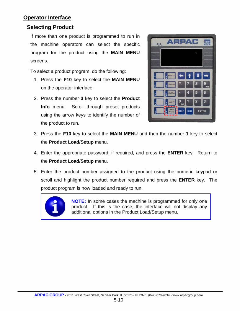
ARPAC GROUP • 9511 West River Street, Schiller Park, IL 60176 • PHONE: (847) 678-9034 • www.arpacgroup.com 5-10
Operator Interface
Selecting Product If more than one product is programmed to run in
the machine operators can select the specific
program for the product using the MAIN MENU
screens.
To select a product program, do the following:
1. Press the F10 key to select the MAIN MENU
on the operator interface.
2. Press the number 3 key to select the Product
Info menu. Scroll through preset products
using the arrow keys to identify the number of
the product to run.
3. Press the F10 key to select the MAIN MENU and then the number 1 key to select
the Product Load/Setup menu.
4. Enter the appropriate password, if required, and press the ENTER key. Return to
the Product Load/Setup menu.
5. Enter the product number assigned to the product using the numeric keypad or
scroll and highlight the product number required and press the ENTER key. The
product program is now loaded and ready to run.
NOTE: In some cases the machine is programmed for only one product. If this is the case, the interface will not display any additional options in the Product Load/Setup menu.

ARPAC GROUP • 9511 West River Street, Schiller Park, IL 60176 • PHONE: (847) 678-9034 • www.arpacgroup.com 5-11
Operator Interface
Viewing, Changing and Saving Parameters Program parameters are displayed, changed and
saved using the MAIN MENU screens.
To view and/or change a parameter, do the
following:
To view a parameter(s):
1. Press the F10 key to select the MAIN MENU.
2. Press the number 1 key to select Product
Load/Setup.
3. If prompted for a password, enter it now.
4. Use the arrow keys to scroll through the
parameters.
To change a parameter value(s):
1. Press the INS key. The numeric field will flash.
2. Use the arrow keys to scroll to the field to be modified.
3. Enter the new numerical value and press the ENTER key. The new value will now
be displayed.
If the numeric key displays *** one of the following situations is true:
a) The unit is not communicating with the PLC.
Notify the supervisor or maintenance.
b) The password entered is incorrect or not active.
Exit the menu by pressing the MESGS key and enter the correct password.
c) The entered value is outside the acceptable range; too large or too small.
Re-enter a different value.
NOTE: Not all parameters are used or applicable in all machines. Parameters marked read only or restricted can only be read: They cannot be changed. Parameters marked reserved are not used in the current application.
(Continued on the next page)

ARPAC GROUP • 9511 West River Street, Schiller Park, IL 60176 • PHONE: (847) 678-9034 • www.arpacgroup.com 5-12
Operator Interface
Viewing, Changing and Saving Parameters To save a parameter value(s):
1. Verify that the current parameters result in the machine to operating in a satisfactory
manner.
2. While in the Product Load/Setup screen, press the F2 key. The PLC will now save
the setup.
NOTE: If the operator does not save the setup and enters another product setting, the current setup will be overwritten and lost.
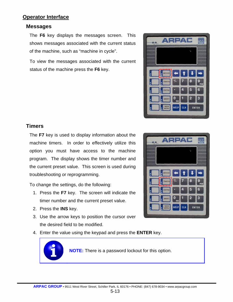
ARPAC GROUP • 9511 West River Street, Schiller Park, IL 60176 • PHONE: (847) 678-9034 • www.arpacgroup.com 5-13
Operator Interface
Messages
The F6 key displays the messages screen. This
shows messages associated with the current status
of the machine, such as “machine in cycle”.
To view the messages associated with the current
status of the machine press the F6 key.
Timers
The F7 key is used to display information about the
machine timers. In order to effectively utilize this
option you must have access to the machine
program. The display shows the timer number and
the current preset value. This screen is used during
troubleshooting or reprogramming.
To change the settings, do the following:
1. Press the F7 key. The screen will indicate the
timer number and the current preset value.
2. Press the INS key.
3. Use the arrow keys to position the cursor over
the desired field to be modified.
4. Enter the value using the keypad and press the ENTER key.
NOTE: There is a password lockout for this option.
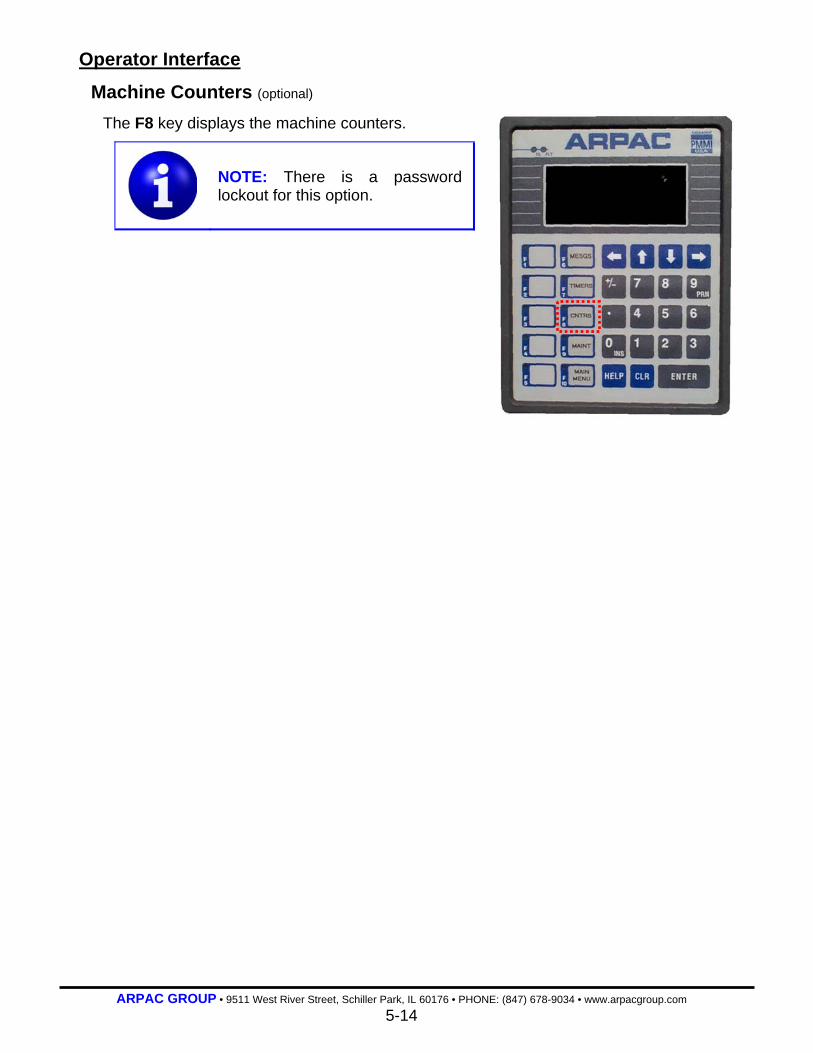
ARPAC GROUP • 9511 West River Street, Schiller Park, IL 60176 • PHONE: (847) 678-9034 • www.arpacgroup.com 5-14
Operator Interface
Machine Counters (optional)
The F8 key displays the machine counters.
NOTE: There is a password lockout for this option.

ARPAC GROUP • 9511 West River Street, Schiller Park, IL 60176 • PHONE: (847) 678-9034 • www.arpacgroup.com 5-15
Operator Interface
Maintenance
The F9 key displays a menu of screens associated
with the maintenance functions of the machine.
These screens are primarily used to perform
preventive and corrective maintenance. To view
any option, select the option by pressing the
corresponding number. To change an option, follow
the directions on the screen.
The following options are displayed when the F9
key is pressed:
Machine Settings—depending on the machine, this
option allows the operator to view and change
machine settings, such as the number of times the machine will cycle when the low film
alarm is sounded.
Override Interlock—allows the operator to override the wrapper, regardless of signals
received from other equipment. Select option using numeric keypad and press the F1
key to toggle option on and off.
Troubleshooting—gives data regarding the function of the machine and the number of
times each of these actions is performed is recorded. This information is helpful when
troubleshooting and allows the user to identify what is happening to cause a fault
condition. During normal operating conditions these values should be equal. Press the
F1 key to reset the data.
PLC Functions—allows the machine to be run in either RUN or PROGRAM mode. The
RUN option should be selected unless a qualified, trained engineer is performing
programming functions on the machine. On some machines a key is needed to change
this setting.

ARPAC GROUP • 9511 West River Street, Schiller Park, IL 60176 • PHONE: (847) 678-9034 • www.arpacgroup.com 5-16
Operator Interface
Main Menu
The F10 key displays a menu of screens associated
with machine set up functions. These screens are
primarily used view and change settings related to a
specific product. General data about the product
profiles and the number of products run is also
available. To view any option, select the
corresponding number of the option. To change an
option, follow the directions on the screen.
The following options are displayed when the F10
key is pressed:
Product Load/Setup—allows operator to view
current settings for a specific product.
Production Data—displays the current number of product that has been run through the
machine. Press the F1 key to zero out this count. This data is not kept in history and will
be lost if the F1 key is pressed.
Product Info—displays product information.
NOTE: There is a password lockout for this option.

ARPAC GROUP • 9511 West River Street, Schiller Park, IL 60176 • PHONE: (847) 678-9034 • www.arpacgroup.com 5-17
Operator Interface
Screen Brightness
NOTE: There is a password lockout for this option. Call Arpac’s technical service or electrical engineering department for the password and keep it in a secure place.
To change the settings use the ARROW keys and
do the following:
1. Press and hold the ENTER key for
approximately three seconds or until an option
screen pops up.
2. Highlight the password option (PSW) and
press the ENTER key.
3. Using the numerical pad enter the password.
The unit will revert to the original screen.
4. Again press and hold the ENTER key for
approximately three seconds or until an option screen pops up.
5. Highlight the system option (SYS) and press the ENTER key.
6. Highlight the brightness option and adjust the brightness to an acceptable level.
7. Highlight the EXIT option and press the ENTER key.
ARPAC GROUP • 9511 West River Street, Schiller Park, IL 60176 • PHONE: (847) 678-9034 • www.arpacgroup.com 5-18
Wrap Pattern Descriptions (Optional) The following are the descriptions of the wrap patterns.
A Standard wrap pattern: Not Applicable on This Machine
1. The machine starts at the bottom and wraps a full web band around the bottom.
The number of wraps depends on the number entered in the base wrap counter.
2. The machine wraps a full web to the top. The speed is dependant on the tower
speed and film carriage raise speed settings.
3. The machine wraps a full web band around the top. The number of wraps depends
on the number entered in the top wrap counter.
4. The machine wraps a full web to the bottom. The speed is dependant on the tower
speed and film carriage lower speed settings.
5. The machine stops and as the wrapped pallet exits the film clamp/cut device cuts
the film leaving the end adhered to the pallet.
B Standard wrap pattern:
1. The machine starts at the bottom and wraps a full web to the top (no base band).
The speed is dependant on the tower speed and film carriage raise speed settings.
2. The machine wraps a full web band around the top. The number of wraps depends
on the number entered in the top wrap counter.
3. The machine wraps a full web to the bottom. The speed is dependant on the tower
speed and film carriage lower speed settings.
4. The machine wraps a full web band around the bottom. The number of wraps
depends on the number entered in the bottom wrap counter.
5. The machine stops and as the wrapped pallet exits the film clamp/cut device cuts
the film leaving the end adhered to the pallet.
C Wrap pattern: Bypass Mode
The turntable conveyor operates as a transfer conveyor in this mode. The rest of
the machine does not function.

ARPAC GROUP • 9511 West River Street, Schiller Park, IL 60176 • PHONE: (847) 678-9034 • www.arpacgroup.com 6-0
SECTION 6
Troubleshooting
6-1 Abnormal Running Conditions 6-1 Turntable Will Not Rotate 6-1 Film Carriage Does Not Rise 6-2 Film Carriage Is At Top and Will Not Descend 6-2 Film Does Not Feed During Wrap Cycle 6-2 Film Carriage Fuse Blows 6-3 Turntable Fuse Blows
6-4 Error Messages 6-4 Film Break
6-4 Gate Door Open (optional)
6-4 Film Saver door Open
6-5 Home Switch Not Sensing
6-5 Both Limit Switches Tripped
6-5 Carriage Travel Time Exceeded
6-6 Carriage Past Bottom Limit
6-6 Carriage Past Top Limit
6-6 Wrap Cycle Time Exceeded
6-6 Carriage travel time exceeded ( 60 sec )
6-7 Safety Eye Blocked While T/table Running
6-7 Wrap Conveyor ran too long
6-8 swing arm jammed
6-8 t/t brake off
6-8 t/t not at home position
6-8 Film clamp open
6-9 top sheet dispenser not at home ( up )
6-9 exit run too long
6-9 tsd not at top position for off mode
6-9 infeed run too long
6-10 load over run stopping position

ARPAC GROUP • 9511 West River Street, Schiller Park, IL 60176 • PHONE: (847) 678-9034 • www.arpacgroup.com 6-1
6-3 Error Messages (Continued)
6-10 tsd safety is engaged
6-11 film unwind run too long
6-11 excessive time tsd lower down detected ( soft limit)
6-11 Pusher safety switch engaged
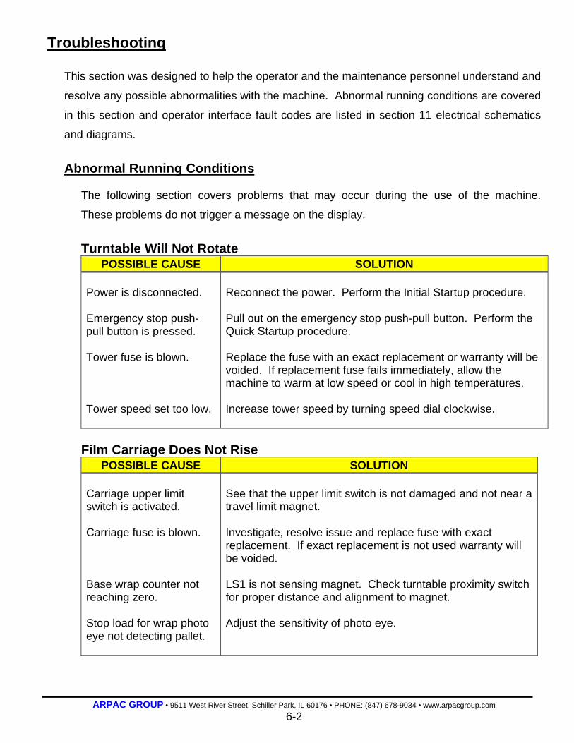
ARPAC GROUP • 9511 West River Street, Schiller Park, IL 60176 • PHONE: (847) 678-9034 • www.arpacgroup.com 6-2
Troubleshooting This section was designed to help the operator and the maintenance personnel understand and
resolve any possible abnormalities with the machine. Abnormal running conditions are covered
in this section and operator interface fault codes are listed in section 11 electrical schematics
and diagrams.
Abnormal Running Conditions
The following section covers problems that may occur during the use of the machine.
These problems do not trigger a message on the display.
Turntable Will Not Rotate
POSSIBLE CAUSE SOLUTION Power is disconnected. Emergency stop push-pull button is pressed. Tower fuse is blown. Tower speed set too low.
Reconnect the power. Perform the Initial Startup procedure. Pull out on the emergency stop push-pull button. Perform the Quick Startup procedure. Replace the fuse with an exact replacement or warranty will be voided. If replacement fuse fails immediately, allow the machine to warm at low speed or cool in high temperatures. Increase tower speed by turning speed dial clockwise.
Film Carriage Does Not Rise
POSSIBLE CAUSE SOLUTION Carriage upper limit switch is activated. Carriage fuse is blown. Base wrap counter not reaching zero. Stop load for wrap photo eye not detecting pallet.
See that the upper limit switch is not damaged and not near a travel limit magnet. Investigate, resolve issue and replace fuse with exact replacement. If exact replacement is not used warranty will be voided. LS1 is not sensing magnet. Check turntable proximity switch for proper distance and alignment to magnet. Adjust the sensitivity of photo eye.
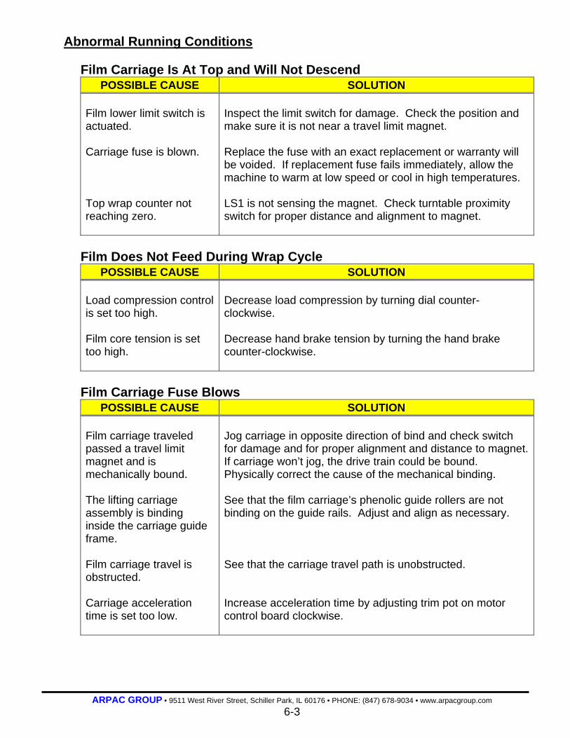
ARPAC GROUP • 9511 West River Street, Schiller Park, IL 60176 • PHONE: (847) 678-9034 • www.arpacgroup.com 6-3
Abnormal Running Conditions
Film Carriage Is At Top and Will Not Descend POSSIBLE CAUSE SOLUTION
Film lower limit switch is actuated. Carriage fuse is blown. Top wrap counter not reaching zero.
Inspect the limit switch for damage. Check the position and make sure it is not near a travel limit magnet. Replace the fuse with an exact replacement or warranty will be voided. If replacement fuse fails immediately, allow the machine to warm at low speed or cool in high temperatures. LS1 is not sensing the magnet. Check turntable proximity switch for proper distance and alignment to magnet.
Film Does Not Feed During Wrap Cycle
POSSIBLE CAUSE SOLUTION Load compression control is set too high. Film core tension is set too high.
Decrease load compression by turning dial counter-clockwise. Decrease hand brake tension by turning the hand brake counter-clockwise.
Film Carriage Fuse Blows
POSSIBLE CAUSE SOLUTION Film carriage traveled passed a travel limit magnet and is mechanically bound. The lifting carriage assembly is binding inside the carriage guide frame. Film carriage travel is obstructed. Carriage acceleration time is set too low.
Jog carriage in opposite direction of bind and check switch for damage and for proper alignment and distance to magnet. If carriage won’t jog, the drive train could be bound. Physically correct the cause of the mechanical binding. See that the film carriage’s phenolic guide rollers are not binding on the guide rails. Adjust and align as necessary. See that the carriage travel path is unobstructed. Increase acceleration time by adjusting trim pot on motor control board clockwise.

ARPAC GROUP • 9511 West River Street, Schiller Park, IL 60176 • PHONE: (847) 678-9034 • www.arpacgroup.com 6-4
Abnormal Running Conditions
Turntable Fuse Blows POSSIBLE CAUSE SOLUTION
Tower brake not released. Tower acceleration time is set too low.
Make sure there is no voltage on the brake and that the brake is mechanically free to rotate. Increase acceleration time by adjusting trim pot on motor control board clockwise.
Error Messages
The following section covers the error messages that may appear on the operator interface,
and the course of action needed to rectify the problems.
Film break The dancer bar has contacted the film break micro-switch.
POSSIBLE CAUSE SOLUTION Film web broken or over-stretched. Misaligned micro-switch adjustment. Defective or broken micro- switch.
Check film and remove bad section or replace film roll. Adjust the micro-switch as necessary. Inspect the switch and wiring. Correct or replace as necessary.
gate Door Open (optional) film saver door open Connection between the respective door micro-switch and magnet has been interrupted.
POSSIBLE CAUSE SOLUTION The respective door has been opened. Door interlock damaged or defective.
Close the door. Inspect the guard door interlock and wiring. Replace if necessary.

ARPAC GROUP • 9511 West River Street, Schiller Park, IL 60176 • PHONE: (847) 678-9034 • www.arpacgroup.com 6-5
Error Messages
Home switch not sensing The rotary tower home switch located at the top of the tower is not reading.
POSSIBLE CAUSE SOLUTION The tower did not rotate. No power to drive motor. Switch is mis-aligned or defective.
Check for and remove blockage. Check and replace fuse if necessary. Check motor and wiring. Repair/replace if necessary. Check switch and alignment. Adjust or replace if necessary.
Both limit switches tripped Both the upper and lower limit switches are tripped at the same time.
POSSIBLE CAUSE SOLUTION Switches or sensing plates are out of adjustment. Switches or wiring is defective.
Check the distance between the switches and the tower. Check the position of the sensing plates located on the tower. Check the switches and wiring. Replace if necessary.
Carriage travel time exceeded The film carriage has not arrived at the upper or lower position in the allotted amount of time.
POSSIBLE CAUSE SOLUTION Speed potentiometer is set incorrectly. Fuse is defective.
Check and adjust carriage raise and lower speed potentiometer(s). Check and replace carriage fuses.
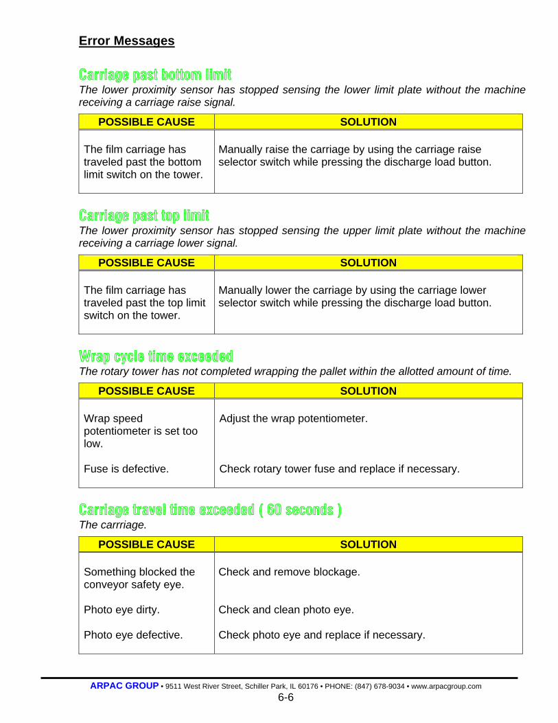
ARPAC GROUP • 9511 West River Street, Schiller Park, IL 60176 • PHONE: (847) 678-9034 • www.arpacgroup.com 6-6
Error Messages Carriage past bottom limit The lower proximity sensor has stopped sensing the lower limit plate without the machine receiving a carriage raise signal.
POSSIBLE CAUSE SOLUTION The film carriage has traveled past the bottom limit switch on the tower.
Manually raise the carriage by using the carriage raise selector switch while pressing the discharge load button.
Carriage past top limit The lower proximity sensor has stopped sensing the upper limit plate without the machine receiving a carriage lower signal.
POSSIBLE CAUSE SOLUTION The film carriage has traveled past the top limit switch on the tower.
Manually lower the carriage by using the carriage lower selector switch while pressing the discharge load button.
Wrap cycle time exceeded The rotary tower has not completed wrapping the pallet within the allotted amount of time.
POSSIBLE CAUSE SOLUTION Wrap speed potentiometer is set too low. Fuse is defective.
Adjust the wrap potentiometer. Check rotary tower fuse and replace if necessary.
Carriage travel time exceeded ( 60 seconds ) The carrriage.
POSSIBLE CAUSE SOLUTION Something blocked the conveyor safety eye. Photo eye dirty. Photo eye defective.
Check and remove blockage. Check and clean photo eye. Check photo eye and replace if necessary.

ARPAC GROUP • 9511 West River Street, Schiller Park, IL 60176 • PHONE: (847) 678-9034 • www.arpacgroup.com 6-7
Error Messages safety eye blocked while t/table running One of the safety photo eyes located at the infeed and exit of the wrap conveyor has become blocked.
POSSIBLE CAUSE SOLUTION Check the infeed and exit of the wrap/turntable conveyor. Photo eye is dirty, mis-aligned or defective.
Remove the blockage. Check the photo eye and repair as necessary.
Wrap conveyor ran too long The pallet tripped the photo eye to start the respective conveyor running but did not trip the next photo eye in the allotted amount of time.
POSSIBLE CAUSE SOLUTION The conveyor moved the pallet forward but something stopped it. The conveyor did not move the pallet forward. The conveyor moved the pallet forward too slowly. The next photo eye is defective, dirty or mis-aligned.
Check for blockage or mis-alignment of the pallet. Check the power to the drive motor for the conveyor. Check the chain that drives the conveyor. Check the speed of the conveyor. Adjust if necessary. Check the next photo eye and repair as necessary. The schematic will indicate the proper photo eye.
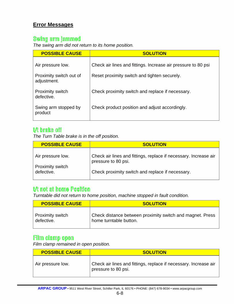
ARPAC GROUP • 9511 West River Street, Schiller Park, IL 60176 • PHONE: (847) 678-9034 • www.arpacgroup.com 6-8
Error Messages Swing arm jammed The swing arm did not return to its home position.
POSSIBLE CAUSE SOLUTION Air pressure low. Proximity switch out of adjustment. Proximity switch defective. Swing arm stopped by product
Check air lines and fittings. Increase air pressure to 80 psi Reset proximity switch and tighten securely. Check proximity switch and replace if necessary. Check product position and adjust accordingly.
t/t brake off The Turn Table brake is in the off position.
POSSIBLE CAUSE SOLUTION Air pressure low. Proximity switch defective.
Check air lines and fittings, replace if necessary. Increase air pressure to 80 psi. Check proximity switch and replace if necessary.
t/t not at home Position Turntable did not return to home position, machine stopped in fault condition.
POSSIBLE CAUSE SOLUTION Proximity switch defective.
Check distance between proximity switch and magnet. Press home turntable button.
Film clamp open Film clamp remained in open position.
POSSIBLE CAUSE SOLUTION Air pressure low.
Check air lines and fittings, replace if necessary. Increase air pressure to 80 psi.
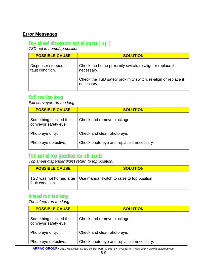
ARPAC GROUP • 9511 West River Street, Schiller Park, IL 60176 • PHONE: (847) 678-9034 • www.arpacgroup.com 6-9
Error Messages
Top sheet dispenser not at home ( up ) TSD not in home/up position.
POSSIBLE CAUSE SOLUTION Dispenser stopped at fault condition.
Check the home proximity switch, re-align or replace if necessary. Check the TSD safety proximity switch, re-align or replace if necessary.
Exit run too long Exit conveyor ran too long.
POSSIBLE CAUSE SOLUTION Something blocked the conveyor safety eye. Photo eye dirty. Photo eye defective.
Check and remove blockage. Check and clean photo eye. Check photo eye and replace if necessary
Tsd not at top position for off mode Top sheet dispenser didn’t return to top position.
POSSIBLE CAUSE SOLUTION TSD was not homed after fault condition.
Use manual switch to raise to top position
Infeed run too long The infeed ran too long.
POSSIBLE CAUSE SOLUTION Something blocked the conveyor safety eye. Photo eye dirty. Photo eye defective.
Check and remove blockage. Check and clean photo eye. Check photo eye and replace if necessary.

ARPAC GROUP • 9511 West River Street, Schiller Park, IL 60176 • PHONE: (847) 678-9034 • www.arpacgroup.com 6-10
Error Messages
Load over run stopping position The load over ran its stopping position
POSSIBLE CAUSE SOLUTION Timer set incorrectly. Something blocked the conveyor safety eye. Photo eye dirty. Photo eye defective. Photo eye mis-aligned
Change timer setting. Check and remove blockage. Check and clean photo eye. Check photo eye and replace if necessary. Check alignment of photo eye and adjust if necessary.
Tsd safety is engaged TSD traveled down too far and safety switch was engaged.
POSSIBLE CAUSE SOLUTION Proximity switch out of alignment. Proximity switch defective.
Check proximity switch alignment position to plate. Use manual switch to raise TSD. Check proximity switch and replace if necessary.
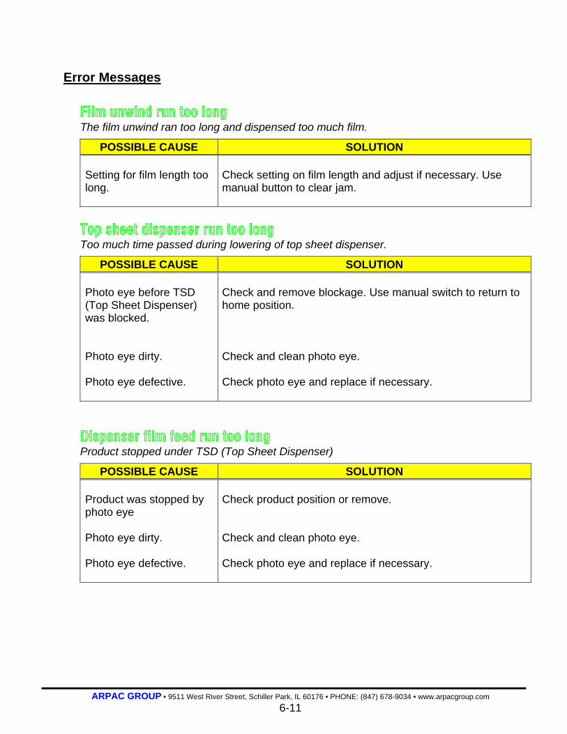
ARPAC GROUP • 9511 West River Street, Schiller Park, IL 60176 • PHONE: (847) 678-9034 • www.arpacgroup.com 6-11
Error Messages Film unwind run too long The film unwind ran too long and dispensed too much film.
POSSIBLE CAUSE SOLUTION Setting for film length too long.
Check setting on film length and adjust if necessary. Use manual button to clear jam.
Top sheet dispenser run too long Too much time passed during lowering of top sheet dispenser.
POSSIBLE CAUSE SOLUTION Photo eye before TSD (Top Sheet Dispenser) was blocked. Photo eye dirty. Photo eye defective.
Check and remove blockage. Use manual switch to return to home position. Check and clean photo eye. Check photo eye and replace if necessary.
Dispenser film feed run too long Product stopped under TSD (Top Sheet Dispenser)
POSSIBLE CAUSE SOLUTION Product was stopped by photo eye Photo eye dirty. Photo eye defective.
Check product position or remove. Check and clean photo eye. Check photo eye and replace if necessary.

ARPAC GROUP • 9511 West River Street, Schiller Park, IL 60176 • PHONE: (847) 678-9034 • www.arpacgroup.com 7-0
SECTION 7
Maintenance
7-1 Break-In Period 7-1 Preventive Maintenance
7-1 Preventive Maintenance Schedule 7-3 Walk-Around Safety Inspection 7-3 Cleaning Pre-Stretch Rollers 7-3 Drive Chains 7-3 Commutator Rings
7-3 Lubrication 7-3 Lubrication Schedule
7-4 Corrective Maintenance 7-4 Turntable Conveyor Removal 7-6 Turntable Conveyor Re-installation 7-7 Film Wipe Cut Arm Swing Adjustment

ARPAC GROUP • 9511 West River Street, Schiller Park, IL 60176 • PHONE: (847) 678-9034 • www.arpacgroup.com 7-1
Maintenance The most important for this or any other machinery is to keep the system clean. It is also
essential to make periodic inspections to detect small problems before they become big
problems. A clean, properly maintained machine enhances productivity. A little P.M. now
goes a long way in future system operation and machine reliability.
Break-In Period The first 100 hours of operation should be considered a break-in period after which the
system should be thoroughly inspected. In general, all assembly hardware such as nuts,
bolts, screws, set screws, bushing and sprocket keys, etc. should be inspected and
tightened if necessary. With power disconnected, check electrical connections at terminal
strips and component terminals for tightness. Other, specific inspections to be made are
listed in the preventive maintenance schedule, which follows.
Preventive Maintenance
DANGER: The following procedures should only be done after the machine has been turned off. Always follow Lockout/Tagout procedures. Always wear safety glasses.
Preventive Maintenance Schedule
Daily
Perform “walk-around” safety inspection.
Clean machine and surrounding area.
Check emergency stop buttons for proper operations.
Weekly
Check drive chain tension.
Clean film saver pre-stretch rollers.
(Continued on the next page)

ARPAC GROUP • 9511 West River Street, Schiller Park, IL 60176 • PHONE: (847) 678-9034 • www.arpacgroup.com 7-2
Preventive Maintenance
Preventive Maintenance Schedule
Quarterly
Check all electrical connections on the commutator rings for tightness.
Every 6 Months
Check film carriage for proper alignment to tower. Tighten or adjust lift chains as
necessary.
Check carriage lift and film saver sprockets for tightness and proper alignment and chains for proper tension.
Check film saver gearbelt for proper tension.
Check carriage travel limit switches for proper operation. Adjust distance as
necessary.
Check commutator rings and brushes for proper alignment. Clean as necessary.
Check machine for gearbox oil leaks.
Replace worn or damaged rollers. Determine cause and fix.
Check condition of safety eye alignment. Test circuit.
Overall check for loose bolts, screws, assemblies, etc.
Overall functionality check.
Check fuses for proper rating.

ARPAC GROUP • 9511 West River Street, Schiller Park, IL 60176 • PHONE: (847) 678-9034 • www.arpacgroup.com 7-3
Preventive Maintenance
Walk-Around Safety Inspection The area around the machine should be kept clean. System component should be free
of dirt, debris, oil spills, and excess grease. Check for loose or damaged components
and wiring.
Cleaning Pre-Stretch Rollers Use naphtha or an equivalent to clean the residue on the pre-stretch rollers. Do not use
acetone. Acetone will make the rubber coating on the rollers brittle.
Drive Chains All drive chains should be checked monthly. Inspect the chain tension and adjust using
the take-up, if necessary. Do not over tighten. It is better for a drive chain to be a little
loose rather than too tight. It is recommended that the drive chains are kept clean and
not lubricated.
Commutator Rings Clean the brush dust off the rings and surrounding area. Check each brush’s alignment
to its ring. Check all electrical components for tightness.
Lubrication
Lubrication Schedule The lubrication schedule is based on continuous use (24 hours per day/365 days per
year) in a relatively clean environment at moderate temperatures. More frequent
lubrication, inspection and cleaning may be needed in more extreme environments.
Component Lubricant Every 2,500 Hours of Operation
Motor speed reducers.
Carriage Lift
Grove. 1 pint – AMGA #7, shipped with mobile 600 W. Super Cylinder. NOTE: Oil should be changed more frequently if reducer is used in a severe environment such as high dust, humidity. Do not mix oil brands as mixing can cause separation resulting in catastrophic component failure.

ARPAC GROUP • 9511 West River Street, Schiller Park, IL 60176 • PHONE: (847) 678-9034 • www.arpacgroup.com 7-4
Corrective Maintenance
Turntable Conveyor Removal The turntable conveyor is held down by gravity alone. However, lifting it up without
disconnecting the electric wires and the pneumatic lines will damage the unit. Use the
following procedure and diagrams to remove the turntable:
NOTE: Before starting this procedure make sure there is a clear area to set the turntable conveyor. It is not always necessary to completely remove the turntable conveyor. In some cases it can be lifted straight up and supported by at least four supporting devices.
DANGER: Be aware that the turntable conveyor is extremely heavy. Follow your company’s safety guidelines when working on or around the turntable conveyor, especially when it is lifted above its normal operating position. It is not recommended to work under it while in the raised position.
1) Disconnect the main power and main air from the equipment.
2) Apply Lockout/Tagout devices to the equipment.
3) Using an allen wrench remove the covers #19 and #20 and the chain guard #12
from the top of the turntable.
4) Place the covers and hardware in a designated place off to the side.
19
12
20
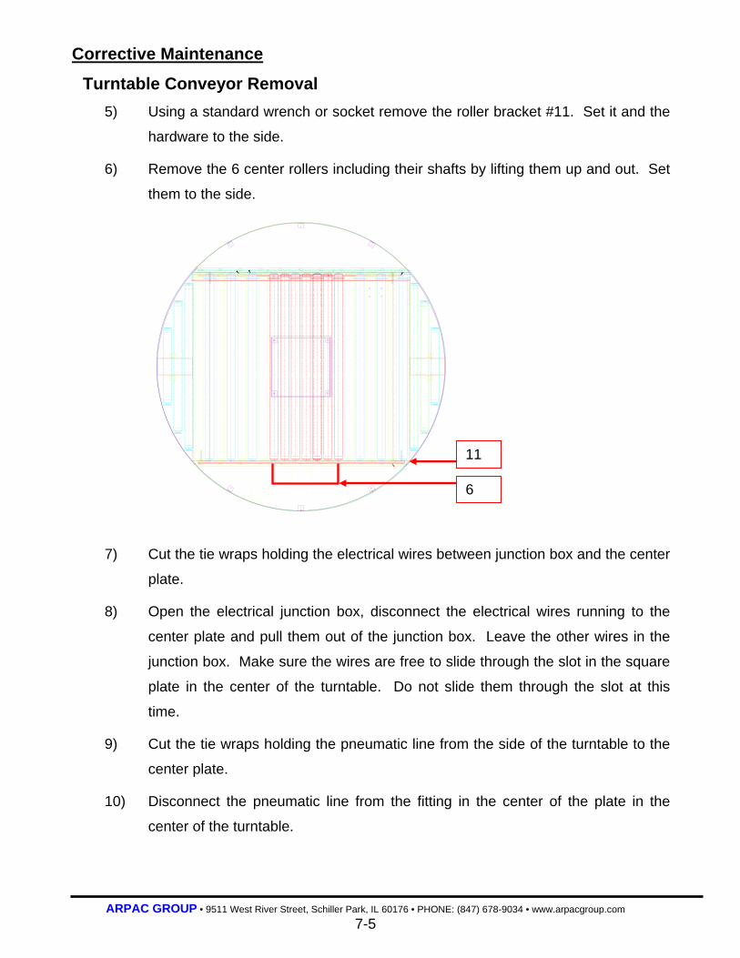
ARPAC GROUP • 9511 West River Street, Schiller Park, IL 60176 • PHONE: (847) 678-9034 • www.arpacgroup.com 7-5
Corrective Maintenance
Turntable Conveyor Removal 5) Using a standard wrench or socket remove the roller bracket #11. Set it and the
hardware to the side.
6) Remove the 6 center rollers including their shafts by lifting them up and out. Set
them to the side.
7) Cut the tie wraps holding the electrical wires between junction box and the center
plate.
8) Open the electrical junction box, disconnect the electrical wires running to the
center plate and pull them out of the junction box. Leave the other wires in the
junction box. Make sure the wires are free to slide through the slot in the square
plate in the center of the turntable. Do not slide them through the slot at this
time.
9) Cut the tie wraps holding the pneumatic line from the side of the turntable to the
center plate.
10) Disconnect the pneumatic line from the fitting in the center of the plate in the
center of the turntable.
11
6
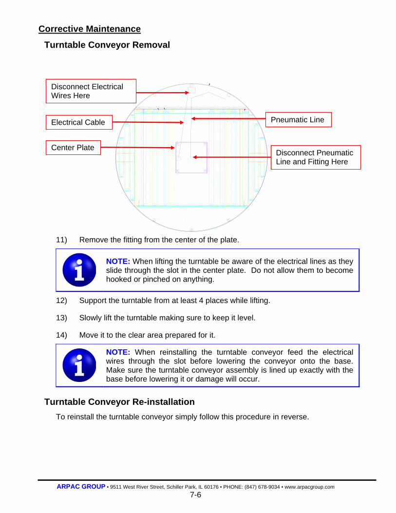
ARPAC GROUP • 9511 West River Street, Schiller Park, IL 60176 • PHONE: (847) 678-9034 • www.arpacgroup.com 7-6
Corrective Maintenance
Turntable Conveyor Removal
11) Remove the fitting from the center of the plate.
NOTE: When lifting the turntable be aware of the electrical lines as they slide through the slot in the center plate. Do not allow them to become hooked or pinched on anything.
12) Support the turntable from at least 4 places while lifting.
13) Slowly lift the turntable making sure to keep it level.
14) Move it to the clear area prepared for it.
NOTE: When reinstalling the turntable conveyor feed the electrical wires through the slot before lowering the conveyor onto the base. Make sure the turntable conveyor assembly is lined up exactly with the base before lowering it or damage will occur.
Turntable Conveyor Re-installation
To reinstall the turntable conveyor simply follow this procedure in reverse.
Disconnect Pneumatic Line and Fitting Here
Disconnect Electrical Wires Here
Center Plate
Electrical Cable Pneumatic Line
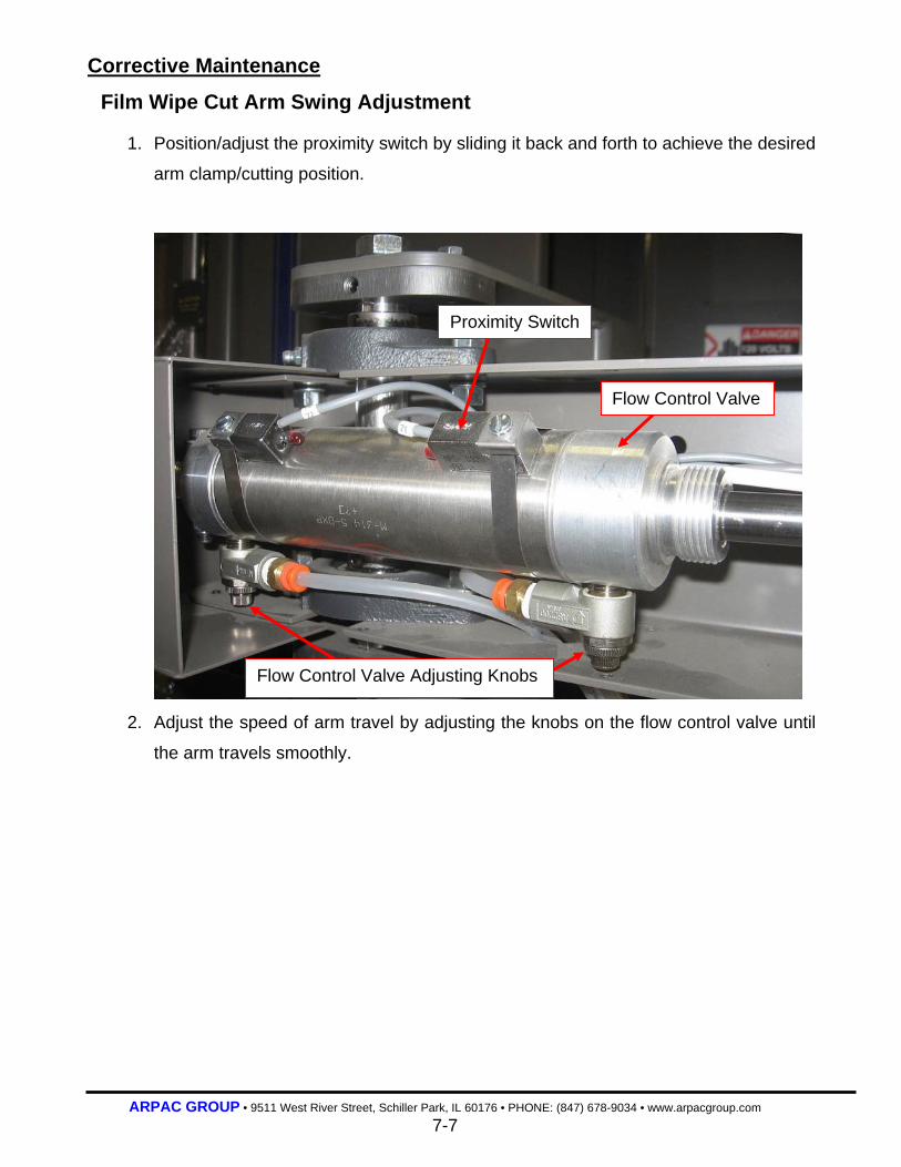
ARPAC GROUP • 9511 West River Street, Schiller Park, IL 60176 • PHONE: (847) 678-9034 • www.arpacgroup.com 7-7
Corrective Maintenance
Film Wipe Cut Arm Swing Adjustment
1. Position/adjust the proximity switch by sliding it back and forth to achieve the desired
arm clamp/cutting position.
2. Adjust the speed of arm travel by adjusting the knobs on the flow control valve until
the arm travels smoothly.
Proximity Switch
Flow Control Valve
Flow Control Valve Adjusting Knobs

ARPAC GROUP • 9511 West River Street, Schiller Park, IL 60176 • PHONE: (847) 678-9034 • www.arpacgroup.com 8-0
SECTION 8
Glossary of Terms

ARPAC GROUP • 9511 West River Street, Schiller Park, IL 60176 • PHONE: (847) 678-9034 • www.arpacgroup.com 8-1
Glossary of Terms
Most every business field has its own language or terminology. The packaging industry is
no exception. This section of the manual, Glossary of Terms, was designed to help the
customer to become more familiar with this terminology. This in turn will help them to
better understand their manual, as well as their machine. Because of the variety of
equipment that ARPAC® designs and manufacturers, not all of the following features or
terms may be applicable to your machine.
Base: The base houses the turntable conveyor, the Tie-ger assembly and the tower assembly.
Casters mounted to the base are used to support the turntable as it rotates.
Brake:
This pneumatic device is used to hold the turntable in place as the turntable conveyor is
in operation. Proximity switches are used to monitor the position of the turntable so the
brake is activated at the correct time. Proximity switches are also used to monitor the
position of the brake device itself. The brake is “on” when it is in the extended position.
Control Module:
This is the cabinet that contains the controls for the machine.
Exit Conveyor:
A conveyor with the entrance end curved to match the turntable conveyor and the exit
end flat to match the infeed conveyor.
FLM SAVR®:
The mechanism used to feed film as the turntable turns.
Film Clamp:
Used to hold the film on the turntable as the machine wraps the product. Use the clamp
open/close push button to control this mechanism.
ARPAC GROUP • 9511 West River Street, Schiller Park, IL 60176 • PHONE: (847) 678-9034 • www.arpacgroup.com 8-2
Glossary of Terms
Hot Wire:
A heated wire used to cut the film rope at the end of the wrap cycle.
Home Position:
The orbital ring is in the home position when ring home proximity switch is tripped.
Infeed Conveyor:
A powered roller conveyor that feeds the product into the wrapping area.
Exit Conveyor: A powered roller conveyor that takes the product out of the wrapping area.
Interlocks: Are safety devices which interrupt normal machine cycle when a certain condition is
met; can be guard door interlocks, product accumulation interlocks, etc...
Operator Interface:
The external keypad and message display on the main control panel. The interface
allows the operator to monitor and diagnose problems as well as set timing functions for
conveyors. A security password can lock this feature, making it inaccessible for
unauthorized users.
Photo Eye:
Photo eyes are photoelectric sensors used to detect moving product or machine parts,
and provide input to the PLC. They do this by transmitting a beam of light to a photo
eye receiver.

ARPAC GROUP • 9511 West River Street, Schiller Park, IL 60176 • PHONE: (847) 678-9034 • www.arpacgroup.com 8-3
Glossary of Terms
PLC: Programmable Logic Controller is the programmable microcomputer that reads the
status of inputs, such as switches, photo-eyes and proximity switches. The PLC also
performs programmed logic and controls outputs.
Proximity Sensors:
Typically, an inductive proximity sensor that detects the presence of metal used to
provide input to the PLC, either for normal operation or to detect fault conditions. These
are also known as proximity switches.
Solenoid Valve:
This electrically controlled mechanical device controls the airflow to the pneumatic
cylinders on the machine. These are typically located together at the base of the
wrapper, on the control side.
Safety Fence and Gate:
The safety fence and gate are made of welded, tubular steel and are mounted around
the parameter of the machine to prevent people from contacting the moving parts of the
machine. Magnetic switches are used to signal the machine to stop if the circuit is
broken. All gates must be closed in order to restart the machine.
Wrap Zone: This area is defined by the safety photo eyes attached to the infeed and exit conveyors.
If the photo eyes are blocked while the machine is in the wrap mode the machine will
immediately stop the machine.

ARPAC GROUP • 9511 West River Street, Schiller Park, IL 60176 • PHONE: (847) 678-9034 • www.arpacgroup.com 9-0
SECTION 9
Service Information 9-1 Field Service Policy 9-2 Installation Policy 9-4 Parts Order Form

ARPAC GROUP • 9511 West River Street, Schiller Park, IL 60176 • PHONE: (847) 678-9034 • www.arpacgroup.com 9-1
Service Information This section contains an overview of ARPAC’s field service as well as the form for ordering
parts.
Field Service Policy
Objective To furnish our customer with prompt, competent, and complete service so they can
operate at optimum efficiency.
Service Personnel ARPAC’s field technicians are experienced in the servicing of ARPAC equipment, are
qualified to instruct customer’s personnel in correct operation and maintenance
procedures of ARPAC equipment. ARPAC Field Service Technicians are fully supported
by factory and all Engineering Departments.
Training
ARPAC personnel is available for ARPAC equipment training either on-site/hands on or
in classroom environment, supported by visual aids and literature to be administered
under separate purchase order.
ARPAC Commitment
• Be readily available to communicate with the customer(s).
• Service Technicians available for supervision and instruction of personnel at
prevailing rates and expenses.
• Upon arrival of the ARPAC Service Technician, he should be able to commence
immediately, minimize “downtime” of your production facilities and commence
training of your personnel.
Scheduling Service
At least 10-days advance notice is required for scheduling personnel. Emergencies will
be handled as quickly as possible. Contact the Technical Service Department via
telephone at (847) 678-9034 or by fax (847) 678-2109 for immediate assistance.
ARPAC GROUP • 9511 West River Street, Schiller Park, IL 60176 • PHONE: (847) 678-9034 • www.arpacgroup.com 9-2
Installation Policy
Objective
To furnish our customer with prompt, competent, and complete service so they can
operate at optimum efficiency. Failure to use factory trained personnel for initial
machine start-up may void the warranty.
Service Personnel ARPAC’s field technicians are experienced in the servicing of ARPAC equipment, and
are qualified to instruct customer’s personnel in the correct operation and maintenance
procedures of ARPAC equipment. ARPAC Field Service Technicians are fully supported
by factory and all Engineering Departments.
Training
ARPAC personnel are available for ARPAC equipment training, either on-site hands-on,
or in a classroom environment supported by visual aids and literature to be administered
under separate purchase order.
ARPAC Commitment
• To furnish equipment per quotation.
• Be readily available to communicate with the customer(s) to facilitate start-up.
• Service Technicians available for start-up supervision and instruction of personnel at
prevailing rates and expenses.
• Upon arrival of the ARPAC Service Technician, he should be able to commence
immediately, minimize “downtime” of your production facilities and commence
training of your personnel.
Customer On-Site Preparation • Unload, unpack, and inspect the equipment for any freight damage (apparent or
hidden). If there is any damage, the Bill of Lading will need to be signed, noting the
damage. You will then need to file all the necessary freight claims with the
appropriate carrier. All shipments are freight collect and you are responsible for any
damages in transit.
• Remove all interfering equipment and clear area where equipment is to be installed.
• Assemble/erect subject equipment.
(Continued on the next page)

ARPAC GROUP • 9511 West River Street, Schiller Park, IL 60176 • PHONE: (847) 678-9034 • www.arpacgroup.com 9-3
Installation Policy
Customer On-Site Preparation • Lag system to floor.
• Furnish all electrical wiring and connections per system requirements.
• Furnish any air and/or gas liners and connections if required.
• Integrate with any existing up and/or down stream equipment.
• Provide qualified technicians, operators, and maintenance personnel to start-up
system.
Scheduling Service
At least 10-days advance notice is required for scheduling personnel. Contact the
Technical Service Department via telephone at (847) 678-9034 or by fax (866) 365-4131
for immediate assistance.

ARPAC GROUP • 9511 West River Street, Schiller Park, IL 60176 • PHONE: (847) 678-9034 • www.arpacgroup.com 9-4
Parts Order Form In order for ARPAC to expedite your parts order, the following information is needed:
Model No. Order No. Buyer
Serial No. Request Date Salesperson
S O L D T O
Company _______________________
Address ________________________
City / State ______________ ______
Country ZIP ______ ______________
ATTN: _________________________
S H I P T O
Company _________________________
Address __________________________
City/State _________________________
Country ZIP ________ ______________
ATTN: ___________________________
Buyer Telephone No.
Part Number Qty. Description
Complete the above form and contact ARPAC’s Parts department to place your order.
ARPAC Parts Department Contact Information
Phone (847) 678-9034
Fax (847) 678-2109
e-mail [email protected]
Open for service Monday through Friday, 7:00 AM to 6:00 PM (Central Time)

ARPAC GROUP • 9511 West River Street, Schiller Park, IL 60176 • PHONE: (847) 678-9034 • www.arpacgroup.com 10-0
SECTION 10
Mechanical Assembly Drawings Notice from ARPAC’s Documentation Department
1. Please refer to your serial specific bill of material sheet (not the bill of material on the drawing) when ordering parts.
2. When multiple drawings are noted, only the drawings applicable are printed.