operation and installation manual - g-scale graphics · operation and installation manual g-scale...
TRANSCRIPT

Page
Revision C: Updated 2/7/2018
Operation and Installation Manual
G-Scale Graphics 5860 Crooked Stick Dr.
Windsor, CO 80550 970-581-3567
www.GScaleGraphics.net
Revision 55: Updated 2/7/2018
The Next Generation of
Page 2
Contents
Page Overview ………………………………………………………………………….. 3 The Radio System ……………………………………………………………….. 4 The RailBoss Control Board …………………………………….………...……. 4 Kid’s Transmitter …………………………………….………………...…...……. 5 Installation ……………………………………………………….…….…………. 6 Setup and Testing ……………………………………………….………….…… 8 Manual Operation ………………………………………………..……….……… 9 Throttle Programming ………...………………………………………..……….. 9 Low Battery Warning …………….……………………………………..……….. 10 Transmitter Command Summary ……………………………………..……….. 11 Trouble Shooting Manual Operation ………………………...…..……..……… 12 Automated Operation ……………………..……………………………...……… 13 Trouble Shooting Automated Operation ……………………..……..……..…… 14 Multi -Train Operation …..……………………..……..……………………..…… 15 Trouble Shooting Multi-Train ……………………..……..…………………….… 16 User Programming ………………………….....……..……………………..…… 17 User Programming Chart ……………………………..……….....……..……… 19 Specifications ……………………..……..…………………………………..…… 20 RailBoss Product Comparison …………………………………………………. 21 Wiring Diagram ……………………..………………………………….....……… 22

Page 3
Overview
RailBoss 4 Basic is an electronic speed control designed specifically for controlling large scale trains using a small hand-held 2.4GHZ transmitter. It provides all of the basic speed control and sound functions you would expect.
Precise speed control with selectable rates for switching or prototypical acceleration (momentum)
Speed matching via min/max throttle limits
Directional lighting outputs for lamps or LEDs (with no external resistors)
Four sound trigger outputs
User programmable
User feedback for radio range testing
Kid’s transmitter (optional) Many aspects of the throttle are programmable to match your specific needs; i.e. double-heading locos, realistic response, and speed limiting for children. The 2.4GHz radio system has no frequencies or channels to worry about. Your transmitter controls your receiver (or receivers) and no one else’s. The radio interference generated by the electric motors powering our locos is no longer a problem. Radio range is excellent and the transmitter easily fits in a shirt or pants pocket. A powerful micro-controller handles all of the control logic and sends signals to a 5 amp motor driver, which is enough to handle most locomotives pulling a full train. Typical current draw for one loco motor is less than 1 amp. The optional 10 amp motor driver will handle multiple loco consists running from one controller. Directional lighting outputs are provided for incandescent lamps and/or LEDs without the need for added resistors. User programmable options give you control over many of the operating parameters, without a computer. In addition to controlling speed via Faster/Slower buttons, the 6-button transmitter can also control loco direction, sound triggers, un-couplers, momentum on/off, track whistle on/off, station stops on/off, and more. A 2-button Kids’ Transmitter is also available, which allows them to blow the whistle/horn, sound the bell, and start the train from a station stop. They have fun. Your train stays on the tracks!
RailBoss 4 Plus has all of the Basic RailBoss functions plus these:
Automated station stops with statistical control via track magnets
Automatic spacing of multiple trains running on the same loop (RB4 20 and later software)
Low battery warning and cutoff for Lithium-Ion and Li-Po battery packs
Statistical control of the track activated whistle
Two high current outputs for Phoenix remote un-couplers, smoke units, or other accessories Automate your layout with automated station stops, back ‘n forth trolley operation, or multiple trains running on the same loop with automatic train separation (Multi-Train for RB4 20 and later software). Gain control over your track magnet triggered whistle. You decide when and how often it is activated. A low battery warning function for use with today’s lithium battery technologies (Li-Ion & Li-Po) lets you get the train back home before it stops dead somewhere out on the layout due to the protection circuit built into the bat-tery pack.
Integrated receiver/electronic speed control and hand-held transmitter

Page 4
Locomotive Hardware consists of a RailBoss 4 Rx (combined control board and receiver, 3.2” X 2.0” ), and an optional reed switch for automated station stops (the Bell reed from your sound system can be used for both station stops and the bell). The Handheld Transmitter can be used to control your entire fleet of locos, any one at a time. Or multiple transmitters can be used to run multiple trains at the same time. To complete your battery power conversion, you will also need to provide a power on/off switch, charging jack, battery pack, and battery charger. To make this task easier, we recommend our “Battery Conversion Module”, which contains a power on/off switch, charging jack, and fast acting fuse. This simplifies the wiring and eliminates most of the soldering. It also provides power distribution to your sound board and other accessories. We also have cables available for: battery connections, and loco to tender or trailing car to loco (2 wire or 4 wire).
The Radio System RailBoss 4 uses a new high-tech 2.4GHZ system designed for industrial use. The range is excellent, up to 400 ft. with the Standard transmitter, or 800 ft. with our Long Range transmitter, and in most cases it still works when the loco is hidden from view. However, obstacles such as trees, dirt, or rock will reduce range. The radio in each transmitter and each locomotive is actually a transceiver, so bidirectional communications be-tween every radio is possible. When running in “Multi-Train” mode, all locos are in constant communication with each other to report their track position. In fact, if you have multiple locomotives running, the system will act as a mesh network, relaying signals via the most reliable radio path to your loco. One transmitter can be used to control your entire fleet of locos, any one at a time. Just turn on the loco you want to run, and the others off. Each RailBoss 4 Rx “learns” a transmitter and will only respond to that transmitter and no others. Press the Learn button on the RailBoss 4 Rx. The LED and front headlight will start blinking. Press the Stop key on the transmitter until the LED stops blinking. They are now linked together. If you routinely need to pass control of a locomotive from one transmitter to another, this can be done without accessing the RailBoss 4 Rx by mounting a remote push-button on your locomotive (see wiring diagram). Multiple transmitters can be used to run more than one train at a time, without interference. There are no channels or frequency selections to worry about. Interference from locomotive motors or other radio/noise sources is not a problem. No filters or special antenna placement is required. The 6-button handheld transmitter uses two AAAA batteries in the Long Range transmitter. There is no on/off switch. It is always ready to use, and only transmits while a button is pressed.
The RailBoss Rx Control Board The RailBoss 4 Rx is a combination control board and radio transceiver. Transmitter commands control a power-ful (and silent) PWM (pulse width modulation) motor driver designed to allow nice slow prototypical speed control of your locomotive. Adding momentum to the throttle enhances the prototypical operation. Momentum is fully pro-grammable, and can be turned on and off via the transmitter to assist with switching operations. RailBoss 4 Rx operates over a wide range of battery input voltage (7-25V, i.e. 2-6 Lithium cells, or 7-16 NiMh/NiCad cells). The battery input is protected from damage due to reverse polarity. RailBoss 4 Rx has directional lighting outputs capable of driving incandescent lamps or LEDs without the need

Page 5
for user supplied resistors. Lamps are powered from the battery voltage. LEDs are powered from a current source built into the RailBoss 4. The front and rear lights follow the direction of the locomotive. The front light is also used as feedback to the operator during programming procedures and low battery warning. Four user defined outputs controlled from the transmitter can be used for sound triggers, phoenix un-couplers, or smoke units. Switch inputs are provided for automating station stops, control of the track activated whistle, and remotely learn-ing a transmitter. A DIP switch, push-button and LED provide simple user programming for many different functions. The integrated 2.4GHZ radio receiver and antenna provide excellent operating range.
Kid’s Transmitter An optional Kid’s TX is available to let your kids have some control without wrecking the train! (RB4 40 and later software) The left button will sound the horn/whistle and the right button rings the bell. Pressing either button while the train has made an automated station stop will make it leave the station. You still have full control using your full 6-button transmitter. Of course the kids may just keep pressing the buttons as fast as they can, so user programmable parameter 8 allows you to lockout the buttons for X seconds before they will work again. (Teaches them patience.) Learn the Kid’s TX by pressing the Tx Learn button on the RB4 board and then press either the Whistle or the Bell button on the Kid’s TX.
Outputs for Sound Triggers, Lights, Un-Couplers, or smoke units Switch Inputs
User Programming & Diagnostic LED
Power In Motor Out
2.4GHZ Radio & Antenna
Tx Learn
RB4 Plus 10 amp Rx/ESC
3.2” X 2.0”

Page 6
Installation Track Power to Battery Power Conversion All track powered locomotives are very simple, electrically. Track power is picked up from the rails via pickups and usually connected directly to the motor. Sometimes there are switches in the circuit to reverse polarity or turn off track power. These connections need to be modified in order to properly connect the battery powered driver board. Converting to battery power consists of these basic steps. 1. Determine battery voltage requirements.
Before you disturb any wiring, run your locomotive at the fastest speed you like to run on your layout and measure the track voltage. Add at least 2 volts to this measurement to account for low batteries and driver losses. If using NiCad or NiMh batteries, round this value up to the nearest 1.2v increment, and you have the number of cells you need. For lithium cells, round up to the nearest 3.7v increment. For example: Track voltage measures 11.6V at speed. (11.6 + 2)/ 3.7 = 3.7. Rounding up to 4, you will need a 4 cell Lithium-Ion battery pack. 4 X 3.7V = 14.8V. (14.8V is a popular value for steam locomotives. Many crit-ters can run on 12V. Diesels may require 18V or more).
2. Disconnect the track power pickups.
By isolating your locomotive from track power, you can run more than one locomotive on the same track at the same time, either battery powered or track powered. If you don’t do this, your battery will be directly con-nected to your track power supply, resulting in damage. Note that in doing this, you have also removed power from all lighting circuits, smoke units, and any other accessories that were running from track power. For bat-tery power, smoke units are usually not used due to the high current requirements that will quickly drain the battery pack. Understanding existing wiring and/or circuit boards without documentation can be difficult. You may choose to just remove it all and wire directly to the things you can see and understand.
3. Find a direct connection to the motor.
The output of the controller needs to be connected directly to the motor. All other control boards and switches should be removed from the circuit. Depending on the design of the locomotive, this may be an extremely simple process, or it may be difficult. Some motor blocks make it very simple. You will find two pairs of wires. One set goes to the track pickups, and the other goes to the motor. You can verify which pair goes to the track pickups using a continuity checker or ohmmeter. Track pickups will have continuity from one pin to one set of wheels. The motor will read a small resistance value across the two wires (e.g. 18 ohms). Simply dis-connect the track pickup pair and connect the motor pair to the controller.
4. Install the discrete components and wire them together (battery pack, power on/off switch, fuses, charging jack, controller, Receiver, and lights)
Installing the new components is a packaging exercise. Where will it all fit? Space for the battery pack and control board and receiver is usually the biggest consideration. For smaller locos you may need to install some of all of the system in a trailing car. The G-Scale Graphics “Battery Power Conversion Module” makes installation easier in many cases by putting the on/off switch, fuse, and charging jack all one small circuit board with screw terminals to eliminate soldering.
Wiring Always use stranded wire and tin the ends with solder prior to making any connections. Wiring for the power input and motor output circuitry on the terminals marked B+,B-,M+,M- needs to be heavier gauge wire (20 or 22 Ga.) Any wiring connections or splices not directly connected to a component must be covered. Use heat shrink tubing or wire nuts are more reliable than tape. Skills All connections to the RailBoss Control can be made via screw terminals. However, basic wiring and soldering skills may be required to make proper connections to the power on/off switch and charging jack. Some drilling and minor fabrication or modifications to the unit under conversion may also be required.
Tools & Materials A low wattage soldering iron, side cutters, needle-nose pliers, wire strippers, a 1/16” or 5/64” slotted screwdriver, resin core solder, 22 Ga. Wire, and heat shrink tubing are recommended to properly complete the wiring. A suit-able drill and double-sided foam tape may be useful for mounting components.

Page 7
Installation of the RailBoss Control Board The RailBoss board can be mounted most anywhere, but allow space for access to wiring, and no metal should be in contact with the board. The power components (large metal tabs) will get hot, so keep them out of direct contact with plastic. Holes in the corners of the board can be used for screws and/or PCB stand-offs. Make sure the stand-offs don’t touch any circuit board components. Or double-sided foam tape on the bottom side of board can be used to secure the board to a plastic surface. Handle the board by the edges, avoiding direct contact with the circuitry. Static electricity can damage the components. Try to ground yourself by touching something metal prior to handling the board. Refer to the wiring diagrams at the end of this manual. Power Input (Battery) The RailBoss Control will not function below 7v input at terminals B+, B-. Reverse polarity will not cause damage, but the RailBoss will not operate. This product is not intended for track power applications where polarity reverses. The higher the battery voltage the more heat the RailBoss will produce. Voltage in excess of 25V may damage circuit board components. Battery packs of 7 to 16 NiMh/NiCad cells or 2 to 6 Lithium-Ion/Polymer cells are suit-able. When making wiring connections to the battery pack, use extreme caution to avoid shorting the leads together. Do not connect the battery to the circuit until all other wiring has been completed. The battery pack should have a quick disconnect connector for safety and ease of replacement.
The power on/off switch can be located on the floor under the loco. If you have a critter, the charging jack can also be floor mounted, since you will probably take it off the track for charging. For a full size locomotive and/or tender, you may want to locate the charging jack on the end of the car to enable charging in place on the track. The switch in the charging jack isolates the battery from all other electronics when a jack is plugged in, regardless of the position of the power on/off switch. Note: A G-Scale Graphics “Battery Conversion module” will greatly simplify the power input wiring and provide screw terminals for connections. A 5-amp fuse in-line with the battery input is recommended. This is also included in the G-Scale Graphics “Battery Conversion module”. (10 amp models should use a 10-amp fuse). Motor Output Connect directly to the motor. All other unknown circuitry should be disconnected from the motor. A maximum of 5 amps continuous current is available from the board. Warning! At max current the power transistors on the board (metal tabs) will be extremely hot. Enough to burn you if touched, or melt any plastic they come in contact with. At power-up the motor output will provide a voltage to the motor that is positive on terminal M+, negative on M-. This is intended to be the forward direction of the locomotive. Outputs for Lighting and other devices Lamps: Terminal 1 provides battery power for Incandescent lamps. So the voltage rating of your lamps must match the battery voltage. When battery voltage exceeds the lamp rating, use a resistor of appropriate value in series with terminal 1. Multiple lamps may be connected
in parallel, but total current draw for terminals 3,4,5,6,7, or 8 should not exceed 250 ma each. Terminals 9 and 10 should not exceed 5 amps each. LEDs: Terminal 2 provides an 11ma current source for LEDs. No current limiting resistors are required. Connect LEDs; terminal 2 to the anodes(+), and terminals 3 and 4 to the cathodes(-) of the forward and reverse LEDs re-spectively. Multiple LEDs can be connected in series.
LED
Page 8
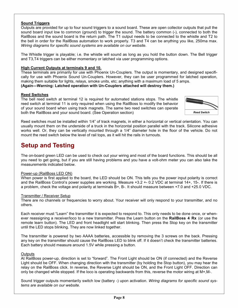
Sound Triggers Outputs are provided for up to four sound triggers to a sound board. These are open collector outputs that pull the sound board input low to common (ground) to trigger the sound. The battery common (-), connected to both the RailBoss and the sound board is the return path. The T1 output needs to be connected to the whistle and T2 to the bell in order for the RailBoss automation to work properly. T3 and T4 can be anything you like, 250ma max. Wiring diagrams for specific sound systems are available on our website. The Whistle trigger is playable; i.e. the whistle will sound as long as you hold the button down. The Bell trigger and T3,T4 triggers can be either momentary or latched via user programming options. High Current Outputs at terminals 9 and 10. These terminals are primarily for use with Phoenix Un-Couplers. The output is momentary, and designed specifi-cally for use with Phoenix Sound Un-Couplers. However, they can be user programmed for latched operation, making them suitable for lights, relays, smoke units, etc; anything with a maximum load of 5 amps. (Again—Warning: Latched operation with Un-Couplers attached will destroy them.) Reed Switches The bell reed switch at terminal 12 is required for automated stations stops. The whistle reed switch at terminal 11 is only required when using the RailBoss to modify the behavior of your sound board when using track magnets. The same two reed switches can operate both the RailBoss and your sound board. (See Operation section) Reed switches must be installed within 1/4” of track magnets, in either a horizontal or vertical orientation. You can usually mount them on the underside of a truck in the horizontal position parallel with the track. Silicone adhesive works well. Or, they can be vertically mounted through a 1/4” diameter hole in the floor of the vehicle. Do not mount the reed switch below the level of rail tops, as it will hit the rails in turnouts.
Setup and Testing The on-board green LED can be used to check out your wiring and most of the board functions. This should be all you need to get going, but if you are still having problems and you have a volt-ohm meter you can also take the measurements indicated below. Power-up (RailBoss LED ON) When power is first applied to the board, the LED should be ON. This tells you the power input polarity is correct and the RailBoss Control’s power supplies are working. Measure +3.2 +- 0.2 VDC at terminal 14+, 15-. If there is a problem, check the voltage and polarity at terminals B+, B-. It should measure between +7.0 and +25.0 VDC. Transmitter / Receiver Setup There are no channels or frequencies to worry about. Your receiver will only respond to your transmitter, and no others. Each receiver must “Learn” the transmitter it is expected to respond to. This only needs to be done once, or when-ever reassigning a receiver/loco to a new transmitter. Press the Learn button on the RailBoss 4 Rx (or use the remote learn button). The LED and front headlight will start blinking. Then press the Stop key on the transmitter until the LED stops blinking. They are now linked together. The transmitter is powered by two AAAA batteries, accessible by removing the 3 screws on the back. Pressing any key on the transmitter should cause the RailBoss LED to blink off. If it doesn’t check the transmitter batteries. Each battery should measure around 1.5V while pressing a button. Outputs At RailBoss power-up, direction is set to “forward”. The Front Light should be ON (if connected) and the Reverse Light should be OFF. When changing direction with the transmitter (by holding the Stop button), you may hear the relay on the RailBoss click. In reverse, the Reverse Light should be ON, and the Front Light OFF. Direction can only be changed while stopped. If the loco is operating backwards from this, reverse the motor wiring at M+,M-. Sound trigger outputs momentarily switch low (battery -) upon activation. Wiring diagrams for specific sound sys-tems are available on our website.
Reed Switch
Page 9
Reed Switches Closing the reed switch with a magnet, or by moving the loco over a track magnet, will cause the LED to turn off while the contacts are closed. If not, check the wiring.
Manual Operation
Power-Up At power-up, the locomotive will be stopped, ready to proceed forward. Momentum is off (fast rate), station stops are disabled and auto track whistle is enabled. Setting Direction Pressing the Stop/Dir button while stopped will change the direction of the loco. Observe the front light of the loco to determine present direction. The loco will power up per User Programming parameter 5. Normal power-up is in the forward direction. When consisting locos, you may need to set this for reverse on power-up for a loco facing backwards. Directional Lighting Front Light is only ON in forward, Rear Light is only ON in reverse. Setting Speed The Faster and Slower buttons will change the speed setting. Momentary presses for small speed changes, or hold the button down to ramp speed up or down. Min and Max Speed settings are set in Throttle Programming mode. The default settings are Min Speed = 0% battery voltage, and Max Speed = 100% battery voltage. Momentum/Fast Rate “Momentum” is a delayed response to a change in speed setting. This simulates the slow response of a heavy train. Toggle the rate from fast to momentum, and vice versa, by pressing “2nd, Stop/Dir”. When toggled, immedi-ate user feedback is provided via the Whistle (Fast Rate) or the Bell (Momentum). Use the fast rate for a quicker response during switching moves. Emergency Stops Holding the Stop button while running will make a quick stop, but not instantaneous. This avoids gear damage due to the real momentum of the train. Manually Triggering Sounds from the Transmitter The Bell and Whistle triggers are accessible directly using the “Whistle” and “Bell” buttons. Out 3 and Out 4 re-quire use of the 2nd key and Whistle (Out 3) or Bell (Out 4). The Bell and Out 3,4 can be programmed for momen-tary or latched operation. The Whistle/Horn will continue to trigger as long as the button is held down, allowing you to “Play” the whistle on some sound systems (Software revision 40 and later). In order to use the manual sound triggers, the sound trigger outputs must be connected to your sound board. Automated Whistle/Horn Triggers from Track Magnets The track activated whistle can be toggled on/off from the transmitter. This is useful when the automated whistle gets annoying or you just want quiet operation. Toggle the track whistle on or off using 2nd key and Faster but-tons. When toggled, immediate user feedback is provided via the whistle. if enabled, the whistle will sound. If dis-abled it will not. When enabled, track magnets will sound the whistle according to the User Programmed setting in parameter 2. Automated Station Stops Automated station stops can also be toggled on/off from the transmitter using 2nd key and Slower buttons. When toggled, immediate user feedback is provided via the bell. if enabled, the bell will sound. If disabled it will not. When enabled, station stops will occur per User Programmed setting in parameter 3. Throttle Programming You can program the min and max throttle speeds (voltage). Most motors require more than 0 volts to get moving, so if you set the min speed just slightly less than what it takes to make the loco move, you will eliminate the delay in getting the loco moving. Max speed setting is useful for setting a safe maximum speed to avoid derailments when children are operating the loco. To enter throttle programming mode, hold the 2nd key, Slower, and Stop buttons down until the LED starts flash-ing at a fast rate. You will now have full speed control from 0 to 100% battery voltage.

Page 10
To set min speed, use the Faster button to just barely get the loco moving. Then use the Slower button to just Stop it. Press Bell to save the min speed (Speed must be less than 50% battery voltage). To set max speed, use the Faster and Slower buttons to run the loco at the desired speed. Press Whistle to save the max speed setting (Speed must be greater than 50% battery voltage). To return to default throttle settings (min speed = 0% voltage, max speed = 100% voltage), press the 2nd key to save the default settings. Press the Stop button to save the setting and exit throttle programming mode. LED will stop flashing. Note: Only one setting, either Min or Max can be set at one time. Exit to save, then re-enter for the second setting. Speed Matching of Locos Use Throttle programming min speed to ensure that both locos start at the same time. Then adjust User Parame-ter 4 to get the same acceleration from each loco. Note: If the top end speeds of each loco differ greatly, this may not work satisfactorily. (The Max speed adjustment won’t help with speed matching). Diesel Consists Diesel consists often require one more of the locos to be facing backwards from the front loco. Use programming parameter 5 to reverse the polarity of the reverse facing loco. It will then power-up in reverse. One transmitter can then control both locos (or more) properly. Assigning the Transmitter to a New Locomotive This is easily accomplished using a remote Learn button (see wiring diagram). Simply press the remote learn but-ton (or the PCB mounted learn button on the RailBoss 4 board), then press the Stop button on the transmitter you want to control that loco with. Low Battery Voltage Warning for Lithium Batteries When NiMh or NiCad batteries start running down, they usually give a noticeable decrease in speed before giving out completely. Plenty of time to get the train back home or to the desired charging location. With lithium batteries, things are different. They need protection from over discharge, so many lithium-ion battery packs have a built-in protection circuit that shuts off the battery when it discharges to a predetermined voltage. This happens with no warning, and your train stops instantly; in the tunnel or on the mountain, etc. Lithium-polymer batteries don’t usually have the built-in protection, but must have some protection to avoid damage. The purpose of the low voltage warning function is to give you full run-time on your battery pack, but warn you when you have only a few minutes left to get the train back to the desired location under power. Low Voltage Warning: The throttle setting is automatically reduced by 50%, the Front Light starts flashing, and you won’t be able to increase speed using the Faster button. Upon release of the Faster button, transmitters equipped with vibration will buzz 3 times. To restore full control, stop the loco using either the Slower or Stop but-tons. You may now return your train to a safe place. The LED will continue to flash and the transmitter will buzz on Faster commands reminding you the battery is very low. The alarm setting is programmable via DIP switch pa-rameter 7. It may take some experimentation to get the desired result; i.e. X minutes of run time before the battery circuit shuts you down. Hard Cutoff: If the battery voltage falls below 3.0 volts per cell, the RailBoss will shut off power to everything it has control of (motor and lights). However, the sound system and other accessories may still be drawing power. This feature is intended for use with Lithium-Polymer batteries, and backup to Lithium-Ion batteries. This function can be disabled or customized using DIP switch parameters 6 and 7: i.e. number of cells and volt-age level. Warning: Neither the Low Voltage Warning nor the Hard Cutoff will function until programming parameter 6 is properly setup. It is the user’s responsibility to determine the proper number of lithium cells in the battery pack being used and select the proper option, thus enabling both functions. These functions serve as a warning only! It the user’s responsibility to intervene promptly after the warning and safely disconnect or charge the battery pack to avoid damage.

Page 11
RailBoss 4 Transmitter Commands
Single Key Function 2
nd Key function
Examples:
Press “Bell” key once to sound the bell.
Press the “2nd
Key”, followed by the
“Bell” key to Toggle Station Stops.
Whistle - Press momentarily to sound the Whistle/Horn (Sound trigger 1) or hold for sound systems with “playable” whistles/horns. Bell - Press momentarily to sound the Bell (Sound trigger 2) Faster - Press momentarily to bump speed up. Hold down to ramp speed up. Slower - Press momentarily to bump speed down. Hold down to ramp speed down. Stop/Dir - Press momentarily or hold to perform a Quick Stop while running. Or while stopped, press momen-tarily to change direction. 2nd - Press momentarily, followed by another key to perform the secondary function. 2nd, Whistle - Sound Trigger 3 or Output 3 2nd, Bell - Sound Trigger 4 or Output 4 2nd, Faster - Toggle the Track activated whistle. Enabled, the whistle sound per User Parameter 2. Disabled it is quiet. Note: Whistle can always be sound manually via a single key press of the Whistle button. Whistle will sound when toggled to “enabled”. 2nd, Slower - Toggle automated Station Stops. Enabled, station stops will occur per User Parameter 3. Dis-able for continuous running. Bell will sound when toggled to “enabled”. 2nd, Stop - Toggle the momentum rate; either fast for switching or slow per User Parameter 4 for prototypical speed changes. Bell will sound when toggled to “enabled”. Throttle Programming - Enter Throttle Programming mode by holding down the 2nd, Slower, and Stop buttons until the LED and Forward head light start flashing. Use Faster/Slower Buttons to control speed (0 to 100%) Press Whistle to set the Max Speed (must be greater than 50%) Press Bell to set the Min Speed (must be less than 50%) Press 2nd to reset throttle to full range (0 to 100%) Press Stop button to exit and save changes at any time. LED will stop flashing. Learn TX - Press the Learn button on the RailBoss 4 Rx. LED will start flashing. Then press Stop on the trans-mitter. LED will stop flashing.

Page 12
Trouble Shooting Manual Operation
The PCB LED and lights turn off as soon as I turn on the RailBoss ...
The RailBoss is shutting down due to low battery voltage (less than 3.0 volts per cell). Recharge or replace the traction battery. Disable or reprogram the Low Voltage Warning parameter (6) for the proper battery size. In order to do this, you will need to enter the User Programming mode right after power-up, before the LED goes out. Set parameter 6 for Op-tion 1 (disabled), or the proper voltage for your battery pack.
Nothing seems to be working … Pressing any button on the transmitter
should cause the RailBoss LED to blink off. If not, check the transmitter battery. It should be 2.5V or greater (3.0V for a new battery).
Check the power. The RailBoss LED should be ON. You should measure be-tween 7 and 25 volts DC applied to ter-minals B+, B- . You should measure 3.2 volts DC on terminals 14(+), 15(-) Verify all wiring connections.
The transmitter doesn't work at all. Did the receiver successfully “Learn” the transmitter? Open the transmitter case and make sure the battery and radio module are full seated. The battery should measure at least 2.8 volts (3.0 volts nominal). Replace the battery with a CR2032 coin cell battery.
Erratic throttle behavior? Reset throttle to default full range values using throttle programming procedure (See Throttle Programming).
The loco doesn’t start moving until I hold the Faster button for a long time. The voltage is ramping from 0 volts to that required to move the loco. You can eliminate this dead time by
programming the Min Speed setting to a higher value. (See Throttle Programming).
The loco starts moving as soon as I turn it on. Program the Min Speed setting to a lower value.
The locos runs in reverse at power up, even though the front light is ON. Reverse the wires at the motor output, terminals M+ & M- . Check setting for Direction Control parameter 5.
The loco won’t run as fast as I like even though I keep trying to increase the speed setting … Maximum speed is determined by your battery voltage or the Max Speed setting. You need more cells/
voltage or you may need to restore the default throttle programming settings.
WhistleTrack
Whistle
FasterOut 3
SlowerOut 4
Stop/DirToggle
Rate
BellStation
Stops
2nd-------
RailBoss 4 Transmitter
With Out 3/4 on the Right
(Older models)
Out 3/4 on the Right is the original label configuration. You may now choose which side you want the Out 3/4 functions to operate on via User Programming Parameter 9. (but the label may read wrong).

Page 13
Automated Operation An automated station stop slows down the train, waits at the station for a predetermined time, then accelerates back to its original running speed. Station stops add interest to your open house or public displays. Automated operation is easily achieved with the RailBoss R/C Control. You just need to add a reed switch to your locomotive and place some track magnets on your layout.
Automated station stops are initiated by a track magnet placed ahead of the station. The magnet initiates decel-eration to a stop. You can make as many stops as you like, one magnet per station. When running in both direc-tions, two magnets per station are required, one for each direction. Place the magnets such that the loco stops at the same location when running from either direction. The magnet in front of the locomotive when leaving the sta-tion will be ignored. The distance the magnet is located from the station will depend on your running speed. Some trial and error will be required to find the proper location and/or speed. Automated reversing is accomplished using a second magnet placed about 6” after the decel magnet. This sec-ond trigger will cause the loco to depart the station in the opposite direction. Magnet spacing requirements vary with speed of the loco. 12” or greater is a good starting point. As long as the second magnet is crossed prior to coming to a full stop, it should work. Caution: Provide end of track bumpers or wheels chocks, just in case. Radio Shack 1/2” round ceramic magnets make good track magnets. They can be glued to the top of a rail tie or placed between the ties. Any magnet of suitable size and strength can be used. But they must be located no more than 1/4” from the reed switch passing overhead. Track magnets mounted higher than the rail tops will be suscep-tible to damage by track cleaners and snow plows. We recommend using movable magnets (next page). Station stops are enabled or disabled from the transmitter while the train is running (see Button Command Sum-mary). During a station stop, transmitter commands are disabled. However, you can give a Faster speed com-mand to leave the station early. Station stops are enabled at power-on. Sound Systems “But I already use magnets to trigger my sound system!” You may have existing track magnets used to trigger the bell and whistle of your sound system. For example; whistle magnet on the right, bell on the left. RailBoss can share these same magnets fairly easily. Install your RailBoss reed switch on the same side you use to trigger the bell. The bell will ring as you approach the station, and the whistle will still blow in your favorite locations. There are several ways to connect your reed switches. A reed switch at terminals 12,13 is required for automated station stops. The reed switch will also trigger the bell (if so desired) via the bell sound trigger output to the sound

Page 14
board. The whistle reed switch can remain connected to your sound board, in parallel with the RailBoss sound trigger, and it will operate as normal. The whistle reed switch at terminals 11,13 triggers the sound board via the whistle sound trigger. The advantage here is, the RailBoss has some optional randomization functions, which will only sound the whistle a certain per-centage of the time the reed switch passes over the track magnet. The result? No more repetitive whistle blowing, lap after lap. It reduces the overall noise, and makes things less predictable. Movable Magnets Being able to easily move your magnets to new track locations makes it much easier to set up your station stops, or change things as the need arises. If you just place a loose magnet in be-tween ties, the metal of the loco may pick it up as it passes. Glue your magnets to a strip of sty-rene as shown. When placed under the rails, the magnet will stay in place. Magnet can be on the left or right by simply rotating the strip. LGB/Piko track magnets also work very well.
Trouble Shooting Automated Operation
Make sure you have enabled station stops from the transmitter.
Loco fails to stop after crossing a single decel magnet. Verify proper installation of reed switch and magnet.
If the loco fails to reverse after crossing two magnets, the magnets are too close together and/or the loco speed is too fast. (Hence the need to protect the end of point-to-point track with a bumper or derail).
The loco will also fail to reverse if the magnets are too far apart and/or the loco is running too slow. It will cross the first magnet, but stop prior to the second, and treat it as a station stop.
If you can’t get the loco to make a proper intermediate station stop in both directions after making the above adjustments, it may be due to excessive grade of the track. Intermediate station stops work best with a flat approach from both directions but should tolerate 3% grades.
The location of the station stop changes over time. Magnet locations are only precise for one given speed setting. As the battery discharges, the loco will slow somewhat, even though the speed setting has not been changed. This effects the stopping distance after a magnet trigger.

Page 15
Multi-Train (Automatic Train Separation) Run two or more trains on the same loop, making random station stops, unattended. Each train will make station stops as programmed in User Parameter 3. When a train stops at the station, it will remain there until another train releases it by passing over a whistle magnet. This timed release of trains prevents faster trains from overtaking slower trains. Of course the trains speeds should be matched fairly close for the best operation. How can this be done without wires? Each locomotive is constantly reporting its track position to the others via radio. The track magnets tell the loco where it is. Since the trains will be making random station stops, they may or may not stop on each lap. When they skip the stop, they will catch the train ahead much sooner. When the lead train senses the train behind is too close, it is forced to skip the station stop, and the train behind is forced to make a station stop, getting everything back in sync. How often your trains stop at the station, and how often they get close to each other depends on the setting in Parameter 3, position of the track magnets, and the length of track available in the “Run” section, and how many trains you are trying to run. More than one Whistle magnet may be used, but the station release will be determined by the first one encoun-tered. Only one station stop per loop. When operating trains on more than one loop, with station stops on each loop, only one of the loops can be operating in Multi-Train mode. A stop command from the transmitter will only stop the one train it is bound to. If you encounter a problem, stop each train using its own transmitter.

Page 16
A single train running in Multi-Train mode will make timed stations stops until a second Multi-Train loco is powered up. Then the train will wait at the station for a release command at the whistle magnet by the second train. Once properly setup, you can enjoy running multiple trains for hours with no intervention. This of course assumes no derailments, no low battery warnings, no interference from little hands, etc. You still need to pay attention to your trains. You can tell when a train is forced to skip a station stop, as the bell will sound, but the train will keep going. If the train is in the middle of slowing down for a stop when told to skip, it will automatically return to running speed.
Trouble Shooting Multi-Train Operation
Station Stops must be enabled. Press 2nd, Bell until you hear the bell. Station stops are enabled at power-up.
User Parameter 3 must be set for a Multi-Train option; 6 thru 9.
If you stop a train with the Transmitter, it will NOT start again automatically. You should stop all trains until the problem causing the stop has been cleared.
You need enough track length in the run section to handle the number of trains you are running without them catching each other, no matter what the station stop % is set to. Increasing the station stop % to 100% will allow more trains to run with reduced risk.
The first whistle magnet (release magnet) must be far enough away from the station stop, such that a train not making a station stop will not run into a train leaving the station, plus some extra running space.
Each train should have the same accel/decel settings for station stops; User Parameter 1.
Make any necessary speed adjustments only while in the “run” section. If you make a speed change dur-ing a station stop accel or decel, speed control reverts to manual mode, and you will need to get the train back to running speed from the transmitter.
If you operate Sound Trigger 3 or 4 while in this mode, you may accidently put that train into manual mode. This happens if the RB4 misses the 2nd key, and thinks you gave a Faster command, instead of the 2nd, Faster commands.

Page 17
User Programming via the DIP Switch & Push Button Some of the operating parameters of the RailBoss Plus can be modified to meet your individual needs. No pro-gramming is necessary to get your system up and running, only to modify it, if so desired. User configurable parameters can be programmed using the 4-position DIP switch, the on-board push-button next to the DIP switch, and on-board LED. The DIP switch selects the parameter to be programmed, and the LED flashes the currently selected option. See the programming chart following this discussion for specific instructions.
Parameter 0
Station Stop Dwell Time
The elapsed time spent from a full stop at the station to departure.
Parameter 1
Station Stop Accel/Decel Time
The time it takes to decelerate to a full stop after crossing the station stop magnet. Use this adjustment not only to make the stop look prototypical, but also to match the characteristics of other locomotives making station stops using the same magnets. Thus, you don’t have to move the magnets for each locomotive.
Parameter 2
Whistle Operation via Reed Switch
The reed switch at terminals 11&13, triggers the output at terminal 5. By connecting your whistle/horn reed switch to the RailBoss, instead of directly to the sound board, the RailBoss can now control its operation. The whistle/horn, especially the grade crossing whistle, gets pretty annoying in a hurry if it sounds every X seconds, lap after lap, all day long at your open house. This parameter allows you to control the percentage of time, that it actually sounds;. e.g. at the 50% setting, after crossing the whistle magnet 10 times, the whistle will have only sounded about 5 times. The triggers are random events, and thus very unpredictable, adding character, and a bit of mys-tery to your layout.
Parameter 3
Station Stops & Bell Operation via Reed Switch
The reed switch at terminals 12&13, initiates a station stop, if enabled from the transmitter, and also triggers the output at terminal 6, normally connected to the bell trigger of you sound board. Like the random whistle function described in Parameter 2, you can randomize your station stops, adding interest for you and your visitors.
Note: When operating in point-to-point trolley mode, using the reversing magnets, you must have pa-rameter 3 set for 100%. Otherwise, the loco will run off the end of the track, as the RailBoss will ignore the mag-nets X% of the time. Multi-Train operations require options 6 thru 9.
Parameter 4
Throttle Momentum
This parameter sets the amount of momentum applied to the throttle when the momentum function is turned ON. “Momentum” is the length of time it takes to accelerate or decelerate while holding down the Faster or Slower but-tons.
Parameter 5
Direction Control
Loco normally runs in the forward direction at power-up. Set this for reverse at power up to run a loco backwards in a consist with other locos.
Parameter 6
Number of Battery Cells
This enables low battery warning and determines the basic voltage of your battery pack; 3.7 volts per cell.
Parameter 7
Low Battery Warning Voltage
This setting finely tunes the warning voltage. Trial and error will determine the best setting. Record the elapsed time between the warning and actual shutdown due either the battery pack protection or the RailBoss hard cut-off. Adjust this parameter for perhaps 10 minutes between warning and shutdown.
Parameter 8
Kid’s Transmitter Delay

Page 18
Buttons won’t work for X seconds after performing a function. Reduces the noise and annoyance factor when small children that just keep pressing the buttons.
Parameter 9
Out 3/4 Transmitter Key Configuration
Outputs 3 and 4 can be configured to operate from either the left side of the TX, under the Whistle and Bell keys, or on the right side, under the Faster and Slower keys. We’ve found that using the left side for these functions may avoid inadvertent speed changes. This option also allows for backwards compatibility with older transmitters, labeled for the right side.
Parameter 10
Bell Configuration
This can be set for a momentary output to trigger a fixed length bell sequence, or a latched output which will tog-gle the bell on or off with each key press.
Parameter 11/12
Out 3/4 Terminal Configurations
Output 3 and 4 can be configured for 4 different functions: Momentary Sound triggers (Terminal 7,8), Latching Lights on/off (Terminals 7,8 - 250 ma max), Latching Lights on/off (Terminals 9,10 - 750 ma max), or Phoenix Un-Couplers (Terminals 9,10). Out 3 activates both terminal 7 and 9. Out 4 activates both terminal 8 and 10. In most cases you will only make one wiring connection to for Out 3, and one for Out 4.
Parameter 11 configures terminals 7 and 8 for either momentary sound trigger operation, or latching lights opera-tion. Parameter 12 configures terminals 9 and 10 for either momentary Phoenix Un-Coupler operation, or latching lights.
Warning: If you have a Phoenix Un-Coupler connected to terminals 9 or 10, and you select Parameter 12 Latch-ing, you will instantly destroy the Un-Coupler. Use Momentary only for Phoenix Un-Couplers (the default option).
Parameter 13
User Feedback
Option 2 enables vibrate mode on transmitters equipped with a vibration motor. Upon pressing any key, the trans-mitter will vibrate if, and only if, the receiver actually received the signal. This can be used for testing radio range of the Standard transmitters. Since the RailBoss 4 control board in your loco uses a Standard radio to return the user feedback to the transmitter, it can only report up to the standard range. Use cell phones and a helper to test long range transmitters.
User Programming / DIP Switch Programming Procedure User configurable parameters can be programmed using the 4-position DIP switch, the on-board push-button next to the DIP switch, and on-board LED.
Enter Programming Mode Hold the button (next to the DIP switch) down on the RailBoss board until the LED goes out. Release the button. The LED will begin flashing the option code of the selected parameter.
Select Parameter Select the parameter you wish to view or program using the DIP switch. (the white square indicates position of the switch; e.g. for parameter 0, all switches are in the down or off position.
View Current Option Code The LED will repeatedly flash the option code for the currently selected parameter; e.g. two flashes followed by a pause indicate option 2.
Change the Option Code Momentarily press the push-button during the pause to advance the option to the next higher number, until you get the desired number of flashes.
Save the Option Code During the pause between code flashes, press and hold down the push-button for about 4 seconds until the LED goes off. Upon release, the LED should stay on solid. This saves the option code and exits User Programming. The new option will now be active.
Exit Programming Mode To exit programming mode without saving any changes, turn off RailBoss power.

Page 19
Option
Parameter 0 - Station Stop Dwell Time
1 10 secs
2 20 secs
3 30 secs
4 40 secs
5 50 secs
6 60 secs
RailBoss 4 User Programming
Plus models Only
Basic and Plus models
Option
Parameter 1 - Station Stop Accel/Decel
1 Slowest
2 Slow
3 Medium
4 Fast
5 Fastest
Option
Parameter 2 - Whistle Operation from Reed Sw.
1 100% (Always triggers)
2 50%
3 40%
4 30%
5 20%
6 0% (Disabled)
Option
Parameter 3 - Station Stops & Bell from Reed Sw.
1 100%(Always triggers, Trolley Mode)
2 75%
3 50%
4 25%
5 0% (Disabled)
6 100% - Multi-Train
7 75% - Multi-Train
8 50% - Multi-Train
9 25% - Multi-Train
Option
Parameter 4 - Throttle Momentum
1 20 secs 0 to 100% Slowest
2 15 secs
3 10 secs
4 6 secs Fastest
Option
Parameter 5 - Motor Direction
1 Normal - Powers up in Forward
2 Reverse - Powers up in Reverse
Option
Parameter 6 - No. of Lithium Battery Cells (3.7V ea.)
1 Disable Low Battery Warning
2 2 Cells, 7.4V
3 3 Cells, 11.1V
4 4 Cells, 14.8V
5 5 Cells, 18.5V
6 6 Cells, 22.2V
7 7 Cells, 25.9V
Option
Parameter 7 - Low Battery Warning Voltage
1 Least run time after warning
2
3
4
5
6
7 Most run time after warning
Option
Parameter 8 - Kid’s Transmitter Delay
1 0 Secs
2 5 Secs
3 10 Secs
4 15 Secs
5 20 Secs
Option
Parameter 9 - Out 3/4 TX Key Configuration
1 Out 3/4 Left side
2 Out 3/4 Right side
Factory settings
Option
Parameter 10 - Bell Trigger Configuration
1 Momentary
2 Latched
Option
Parameter 11 - Out 3/4 Terminal 7/8 Configuration
1 Momentary 7 / Momentary 8
2 Momentary 7 / Latched 8
3 Latched 7 / Momentary 8
4 Latched 7 / Latched 8
The number of LED flashes indicates the Option Number for the Parameter selected by the DIP switch. Note: If your RailBoss 4 board has only 3 switch positions, just assume position 4 is set to Off. The switch settings for Parame-ters 0-7 are valid for your board.
Option
Parameter 12 - Out 3/4 Terminal 9/10 Configuration
1 Momentary 9 / Momentary 10
2 Momentary 9 / Latched 10
3 Latched 9 / Momentary 10
4 Latched 9 / Latched 10
Warning: Use only “Momentary” for Phoenix Un-Couplers. “Latched” will destroy them instantly!
1 2 3 4
ON
1 2 3 4
ON
1 2 3 4
ON
1 2 3 4
ON
1 2 3 4
ON
1 2 3 4
ON
1 2 3 4
ON
1 2 3 4
ON
1 2 3 4
ON
1 2 3 4
ON
1 2 3 4
ON
1 2 3 4
ON
Option
Parameter 13 - User Feedback
1 Disabled
2 Transmitter Vibration
3 Not Used
1 2 3 4
ON
1 2 3 4
ON
Page 20
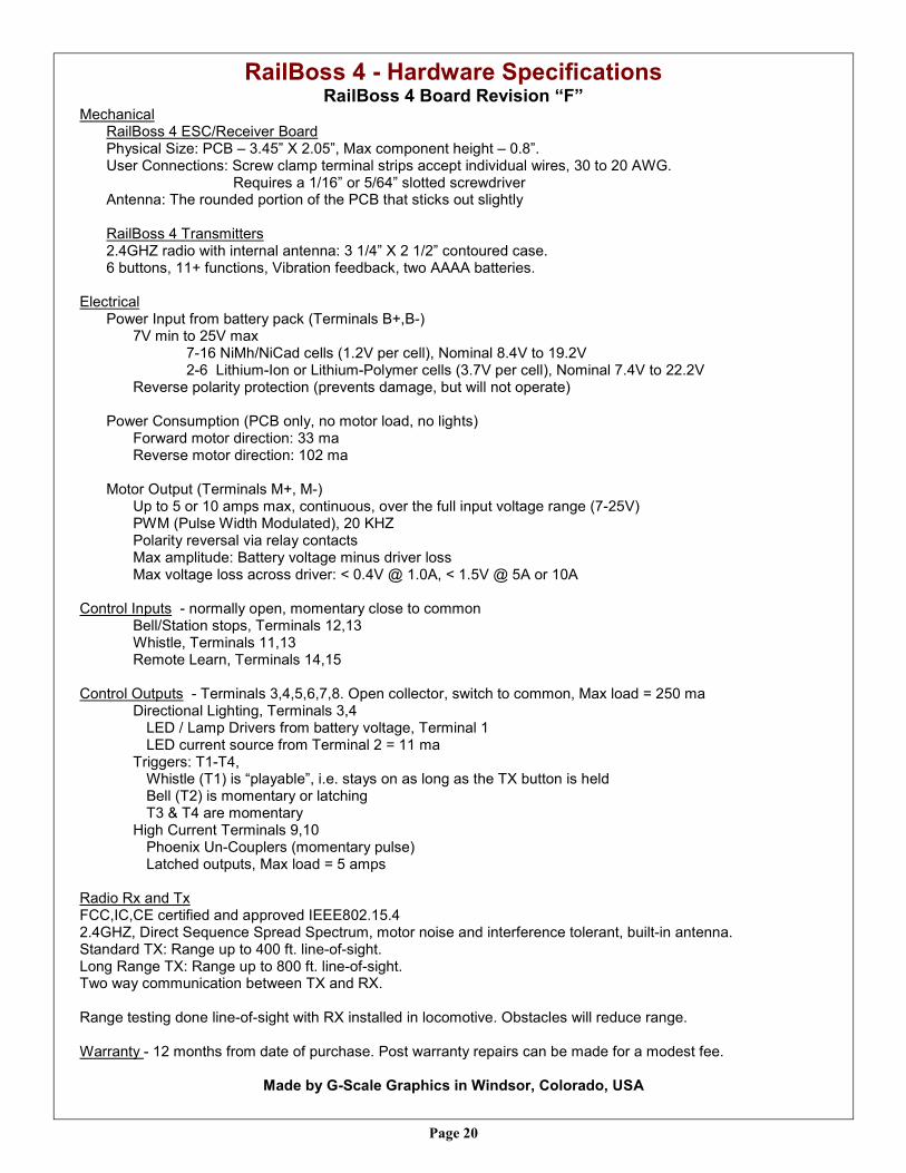
RailBoss 4 - Hardware Specifications RailBoss 4 Board Revision “F”
Mechanical RailBoss 4 ESC/Receiver Board Physical Size: PCB – 3.45” X 2.05”, Max component height – 0.8”. User Connections: Screw clamp terminal strips accept individual wires, 30 to 20 AWG. Requires a 1/16” or 5/64” slotted screwdriver Antenna: The rounded portion of the PCB that sticks out slightly RailBoss 4 Transmitters 2.4GHZ radio with internal antenna: 3 1/4” X 2 1/2” contoured case. 6 buttons, 11+ functions, Vibration feedback, two AAAA batteries.
Electrical Power Input from battery pack (Terminals B+,B-) 7V min to 25V max 7-16 NiMh/NiCad cells (1.2V per cell), Nominal 8.4V to 19.2V 2-6 Lithium-Ion or Lithium-Polymer cells (3.7V per cell), Nominal 7.4V to 22.2V
Reverse polarity protection (prevents damage, but will not operate) Power Consumption (PCB only, no motor load, no lights) Forward motor direction: 33 ma Reverse motor direction: 102 ma Motor Output (Terminals M+, M-)
Up to 5 or 10 amps max, continuous, over the full input voltage range (7-25V) PWM (Pulse Width Modulated), 20 KHZ Polarity reversal via relay contacts Max amplitude: Battery voltage minus driver loss Max voltage loss across driver: < 0.4V @ 1.0A, < 1.5V @ 5A or 10A
Control Inputs - normally open, momentary close to common Bell/Station stops, Terminals 12,13 Whistle, Terminals 11,13 Remote Learn, Terminals 14,15 Control Outputs - Terminals 3,4,5,6,7,8. Open collector, switch to common, Max load = 250 ma Directional Lighting, Terminals 3,4 LED / Lamp Drivers from battery voltage, Terminal 1 LED current source from Terminal 2 = 11 ma Triggers: T1-T4, Whistle (T1) is “playable”, i.e. stays on as long as the TX button is held Bell (T2) is momentary or latching T3 & T4 are momentary High Current Terminals 9,10 Phoenix Un-Couplers (momentary pulse) Latched outputs, Max load = 5 amps Radio Rx and Tx FCC,IC,CE certified and approved IEEE802.15.4 2.4GHZ, Direct Sequence Spread Spectrum, motor noise and interference tolerant, built-in antenna. Standard TX: Range up to 400 ft. line-of-sight. Long Range TX: Range up to 800 ft. line-of-sight. Two way communication between TX and RX. Range testing done line-of-sight with RX installed in locomotive. Obstacles will reduce range.
Warranty - 12 months from date of purchase. Post warranty repairs can be made for a modest fee.
Made by G-Scale Graphics in Windsor, Colorado, USA

Page 21
All of our 2.4GHZ radio transmit-ters are “bound” to the receivers. No channel or frequency selec-tions to worry about. No motor noise suppression or special an-tenna placement required. You can control all of your trains from the same transmitter, any one at time. Separate transmitters are required to run more than one train at the same time. Note 1) Indicated ranges have been tested, line-of-sight to a re-ceiver mounted in a train. Trans-mitter range will be reduced by obstacles, such as trees, dirt, and rock. Results will vary. Note 2) Two of the outputs are available for any combination of sound triggers, un-Couplers, or latched drivers. User programma-ble.
2.4GHZ RailBoss R/C Product Comparison
Control System RailBoss 4 Basic
RailBoss 4 Plus
2.4 GHZ Radio Transmitter
6-Button Handheld TX
6-Button Handheld TX
Rx / ESC Configuration
Integrated ESC/Rx
Integrated ESC/Rx
Radio Components Transmitter and Receivers supplied by
G-Scale Graphics
Transmitter and Receivers supplied by
G-Scale Graphics
Speed Control Push Buttons
Push Buttons
TX Control Range (Note 1)
Standard TX up to 400’ Long Range TX up to 800’
Standard TX up to 400’ Long Range TX up to 800’
Momentum Control X X
Sound Triggers
4 Note 2
Directional Lighting
X X
Kid’s Transmitter 2-Button 2-Button
Two Train Operation From One TX
Low Lithium Battery Warning
X
Automated Station Stops
X
Auto Multi-Trains on Same loop
X
Random Track Whistle X
Dual Phoenix Un-Coupler Outputs or latched 5 amp outs
Note 2
Motor Driver 5 or 10 amps 5 or 10 amps
Radio Range Testing X X

Page 22
Ra
ilB
os
s 4
- W
irin
g D
iag
ram