operation and configuration manual · 6 m300 operating & installation manual installation...
TRANSCRIPT

PENTAIR ENVIRONMENTAL SYSTEMS
M300ELECTROMAGNETIC FLOWMETER
OPERATION AND CONFIGURATION MANUAL

2
M300 Operating & Installation Manual
CUSTOMER SERVICE / TECHNICAL SUPPORT
If you have questions about ordering Pentair Aquatic Eco-Systems replacement parts, and pool products, please use the following contact information:
Customer Service (8:00 AM–7:00 PM Monday to Thursday, 8:00 AM–5:00 PM Friday)
Phone: 407-886-3939 (Local) 877-347-4788 (Toll Free)
Fax: 407-886-6787
Web siteVisit PentairAES.com to find information about Pentair products.
Technical Support
Sanford, North Carolina (8 A.M. to 4:30 P.M. ET)Phone: (919) 566-8000Fax: (919) 566-8920
Moorpark, California (8 A.M. to 4:30 P.M. PT)Phone: (805) 553-5000 (Ext. 5591)Fax: (805) 553-5515
© 2014 Pentair Aquatic Eco-Systems, Inc. All rights reserved.
This document is subject to change without notice.
2395 Apopka Blvd., Apopka, FL 32703, USA Phone: 407.886.3939 Web: PentairAES.com1-21 Monash Dr., Dandenong South, VIC 3175, Australia Phone: 011 61 1 300 137 344
All Pentair trademarks and logos are owned by Pentair or one of its global affiliates. Pentair Aquatic Eco-Systems™, Pentair Environmental Systems™ and Emluc™ are trademarks of Pentair Aquatic Eco-System, Inc. and/or its affiliated companies in the United States and/ or other countries. Unless expressly noted, names and brands of third parties that may be used in this document are not used to indicate an affiliation or endorsement between the owners of these names and brands and Pentair Aquatic Eco-Systems, Inc. Those names and brands may be the trademarks or registered trademarks of those third parties. Because we are continuously improving our products and services, Pentair reserves the right to change specifications without prior notice. Pentair is an equal opportunity employer.
PAES700-6.A 9/11/14
For technical support please quote the following details which are located on rating plate of each instrument.
Serial Number, example 123456
Part Number, example IR2020
Name and Model: M300 Electromagnetic Flowmeter
Power supply, voltage and frequency, if known.
A Product Return Form can be found at the back of this manual.

3
M300 Operating & Installation Manual
TABLE OF CONTENTS
Customer Service / Technical Support ...............2
Table Of Contents ..................................................3
General Description...............................................4
Important Storage and Installation Points ......4
Installation ..............................................................6
Mechanical Installation of Transmitter ............6
Installation of the Detector Head .....................6
Earthing of Detector Head ...............................7
Electrical Installation ........................................8
Configuration .......................................................12
Keyboard Up Arrow Button ............................12
Down Arrow Button ........................................12
Tick Button ......................................................12
Exiting the Configuration Menu .....................12
Display Menu ..................................................12
Configuration Menu ........................................13
Troubleshooting ...................................................18
Display is blank ...............................................18
Message 'Coil Open cct' is displayed ...........18
Display is erratic and does not indicate zero ....................................18
Display does not respond to flow ..................18
Flow rate indicates reverse flow ....................18
4-20mA Output 1 or 2 operates but indicates incorrectly ................................18
4-20mA Output 2 reads zero milliamps .........18
Display has no back lighting ..........................18
Specification ........................................................19
M300 Menu Flowcharts ..................................20
M300 Transmitter Enclosure Detail ...............26
EM Detector Head Dimensions .....................27
EM/IR2060 Series Fabricated Steel Welded Submersible Housing .......................28
Equipment Returned for Testing or Repair .......29
Product Certificate ..............................................31

4
M300 Operating & Installation Manual
GENERAL DESCRIPTIONCongratulations on your purchase of your Australian designed and manufactured M300 Electromagnetic Flowmeter. The M300 flowmeter transmitter is a microprocessor based instrument designed for ease of use and configuration. The M300 has been pre-configured and calibrated to your requirements in our calibration laboratories. However re-ranging and setup may be carried out on site using the front panel display and push buttons or by connecting a PC to the communication port. The menu system has been designed to be user friendly for ease of configuration on site.
All flowmeter heads will be fitted with a tag detailing calibration details to enable configuring of the M300 Transmitter. These details are obtained from wet calibrations carried out in flow laboratory.
In the event of any problem please contact your nearest Combined Instrument Systems representative or, if more convenient, please do not hesitate to consult our head office technical staff.
Always provide the serial number of your particular system which is located on a label mounted on the transmitter. If more accessible, similar information may be obtained from the Flowmeter Detector Head label.
On taking delivery of your M300 electromagnetic flowmeter and prior to installation and operation, we ask you to ensure that you are conversant with the facilities available and precaution to be taken by studying the contents of this manual.
Your M300 electromagnetic flowmeter consists of an electromagnetic detector head (flow tube) which is to be located in the pipework and an electronic amplifier (transmitter).
Many auxiliary instruments may be connected to the M300 electromagnetic flowmeter, for example, chart recorders, flow indicators, etc.
Important Storage and Installation PointsIn order to ensure satisfactory operation of your M300 electromagnetic flowmeter and to avoid the possibility of rendering the guarantee null and void, please ensure that you comply with the following points.
• When stored or installed the flowmeter head cable terminations must be adequately sealed to avoid the ingress of moisture which could lead to internal damage. Similar precautions should be taken with the containing case glands of the wall mounted weatherproof amplifier.
• Ensure that the flowmeter transmitter enclosure is sealed and that the unit is stored in a dry environment if it is not to be put into service immediately upon receipt.
• If the flowmeter head is of the submersible type and the cables are not potted, ensure that the cables entering the head terminal compartment are compatible with the glands provided. Failure to observe this precaution may lead to poor sealing and the ingress of moisture or, in the worst event, flooding of the head interior.
• Ensure that your power supply is compatible with the M300 electromagnetic flowmeter.
• Your flowmeter head is provided with an insulating lining which extends over the flange faces. Do not drag or roll the unit on its end flanges.
• The lining of the flowmeter head is provided to resist corrosion and has been selected to suit the media passing through the bore. While calibration of your M300 system will not change for other media, care should be taken to ensure that the particular lining material is compatible with any change of media. If in doubt contact your nearest representative.

5
M300 Operating & Installation Manual
GENERAL DESCRIPTION• The lining of your flowmeter head is electrically
insulating to provide correct operation, it does not act as a gasket. you must provide gaskets between the flowmeter lining and the adjacent pipework.
• Locate your flowmeter head in a position such that it remains full of liquid at all times.
• The screened signal cable to your flowmeter head should preferably be run in a conduit or trunking reserved entirely for its use. Under no circumstances should the signal cable be run in close proximity to power cables.
• The media at either end of your flowmeter head must be adequately earthed either by direct means of the pipework, if this is electrically conducting, or by the use of earth discs or earthing electrodes. Earthing electrodes cannot be added once the head is manufactured.
• Do not lift or support your flowmeter head by its case. Use eye bolts or lift from the tube neck using sling and spreader.
• Your flowmeter head has been designed to carry its own weight from the end flanges and thus the adjacent pipework. If supports are required these should locate on the flanges.
• If the media passing through the flowmeter head is particularly abrasive the use of a contra flange on the upstream flange is recommended to prevent damage to the leading edge of the lining.

6
M300 Operating & Installation Manual
INSTALLATIONMechanical Installation of TransmitterCheck the Flow Test certificate supplied with the meter to ensure the Detector Head (Primary) and the Transmitter (Secondary) have the correct serial numbers. The serial number on the Flow Tube and the serial number on the Transmitter will not necessarily be the same.
Careful consideration to the initial mechanical installation of the amplifier will provide many benefits ensuring ease of access to cable terminations and internal controls.
The transmitter may be surface or panel mounted, refer to Appendix 2 for panel cutout details.
The M300 electromagnetic flowmeter transmitter is provided with five gland entries. If however, fewer than five glands are used, extreme care should be taken to ensure that the unused entries are adequately sealed.
Always ensure that the flowmeter enclosure is sealed when the unit is unattended.
Installation of the Detector HeadThe detector head may be installed at any angle but it is important to ensure that it is completely filled with liquid whilst in use. It is therefore advisable to place the tube in a position where the pipe line is always full, such as a rising main, or when there is no risk of sedimentation, the bottom of a 'U' bend.
When the detector head is mounted in the horizontal, the termination box must be on top. A flow direction arrow is provided to indicate the direction of flow during calibration and to ensure that the terminations are as per the wiring diagram found at the rear of this manual. If installed in this manner there will be no requirement to reverse wires for correct operation. For correct operation it is essential for the flowing liquid to be earthed at both ends of the detector head. The following methods of earthing are available:
Connection to adjacent metallic pipework is fully acceptable providing such pipework does not contain an electrically insulating lining, for example, bitumen. Earth straps are recommended between the pipework flanges and the flowmeter flanges particularly when flexible self sealing couplings are used. Flange bolts do NOT always provide good electrical earth connections between metallic flanges.
If the adjacent pipework is not electrically conducting or is lined with an electrically insulating material, then earth rings or electrodes must be used. These earth rings must be strapped to the detector head Flanges at either end. In the case of earth electrodes there is no need for further termination as this is carried out at the time of manufacturing.
While your detector head is provided with an Insulating lining extending over the flange faces, this does NOT form a gasket. When installing the detector head, gaskets must be provided between the Flowmeter lining and the adjacent pipework flanges. In the case of earth rings or discs, these should also be installed with a gasket either side.
Particular care should be taken to ensure that entrained air cannot accumulate in the flowmeter head or be swept through it from surrounding pipework, manifolds, etc. Wherever possible the flowmeter electrodes should be mounted in the horizontal plane. With abrasive slurries, vertical mounting is recommended to ensure even distribution of wear in the lining material. If the slurry is of a particular abrasive material, the use of a contra flange on the upstream flange is recommended to prevent damage to the leading edge of the lining. This contra flange is also used in place of one earth ring or disc.
In order to obtain a smooth flow profile and remove turbulence or swirling flow at the flow meter head, sharp bends and valves used to control the flow should not be placed closer than five pipe diameters from the upstream flange.

7
M300 Operating & Installation Manual
INSTALLATIONSmall disturbances to flow, such as may be caused by straight through valves, minor bends and 'T' junctions carrying less than 20% of the flow, will have minimal affect on the performance providing they are no closer than three pipe diameters from the upstream flange.
Little affect will be observed by the presence of bends etc on the downstream flange of the detector head. Where reducers are used, steep tapers of greater than 30° should be avoided.
Valves should not be placed immediately adjacent to the detector head, however for subsequent removal of the detector head, should this ever be necessary, some thought should be given to the manner in which it may be isolated. For dimensions of the detector heads reference should be made to the relevant outline diagram found at the end of this manual.
Note:
Some government authorities have strict requirements for flowmeter installation that may overrule the above advice. Be certain to consult local authorities prior to commencing installation.
Cables between the Detector Head and converter should be run in conduits for protection, and then up the inside of the converter mounting post. Separate conduits are needed for coil supply, signal and accessories.
Earthing of Detector Head
IR2060 OnlyWhile your flow tube is provided with an insulating lining extending over the flange faces, this does NOT form a gasket. When installing the detector head, gaskets must be provided between the flowmeter lining and the adjacent pipework flanges. In the case of earth rings or discs, these should also be installed with a gasket either side.
For correct operation it is essential for the flowing liquid to be earthed at both ends of the detector head. Connection to adjacent metallic pipework is fully acceptable providing such pipework does not contain electrically insulating lining, for example: bitumen. Earth straps are recommended between the pipework flanges and the flowmeter flanges particularly when flexible self sealing couplings are used. Flange bolts do not always provide good electrical earth connections between metallic flanges.
If adjacent pipework is not electrically conducting or is lined with an electrically insulating material, then earth rings or earth electrodes must be used. These earth rings must be strapped to the detector head flanges at either end. In the case of earth electrodes there is no need for further termination as this is carried out at the time of manufacture.
ABS Plastic Detector Heads and Detector Heads Fitted with Optional Earth ElectrodesFor ABS plastic detector heads there is no need for the installation of earth rings or the need to earth the mating pipe flanges as all ABS Plastic detector heads are fitted with earthing electrodes. This is also the case for detector heads that have the optional earth electrodes fitted.
8
M300 Operating & Installation Manual
Transmitter Termination Strip
Mains Supply Wiring (Optional)
Ensure that all unused glands are sealed to prevent the ingress of moisture.
Connect mains power, if supplied as a mains supply unit, to the mains terminals as detailed below:
Use wiring practices that conform to local codes. The ground terminal grounds the instrument which is mandatory for safe operation.
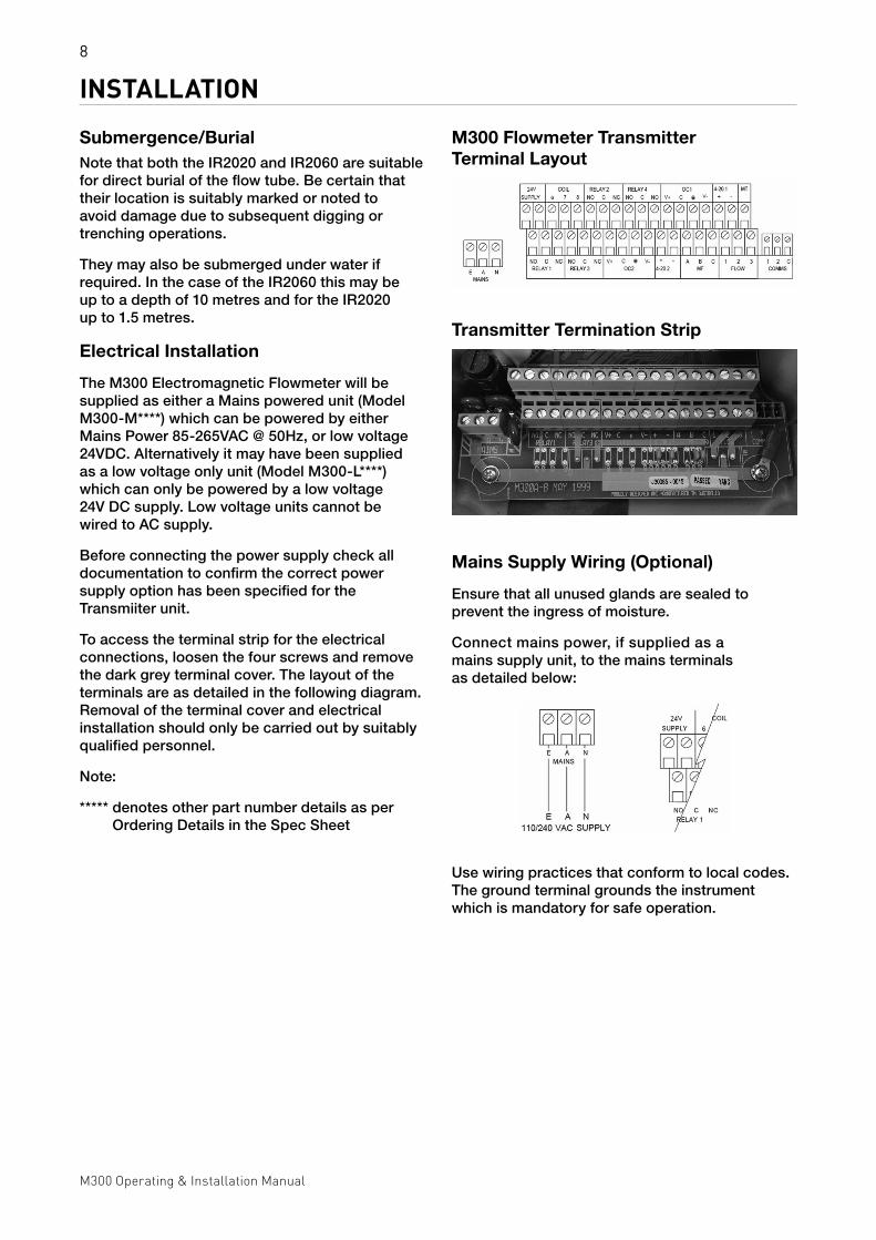
INSTALLATIONSubmergence/BurialNote that both the IR2020 and IR2060 are suitable for direct burial of the flow tube. Be certain that their location is suitably marked or noted to avoid damage due to subsequent digging or trenching operations.
They may also be submerged under water if required. In the case of the IR2060 this may be up to a depth of 10 metres and for the IR2020 up to 1.5 metres.
Electrical Installation
The M300 Electromagnetic Flowmeter will be supplied as either a Mains powered unit (Model M300-M****) which can be powered by either Mains Power 85-265VAC @ 50Hz, or low voltage 24VDC. Alternatively it may have been supplied as a low voltage only unit (Model M300-L****) which can only be powered by a low voltage 24V DC supply. Low voltage units cannot be wired to AC supply.
Before connecting the power supply check all documentation to confirm the correct power supply option has been specified for the Transmiiter unit.
To access the terminal strip for the electrical connections, loosen the four screws and remove the dark grey terminal cover. The layout of the terminals are as detailed in the following diagram. Removal of the terminal cover and electrical installation should only be carried out by suitably qualified personnel.
Note:
***** denotes other part number details as per Ordering Details in the Spec Sheet
M300 Flowmeter Transmitter Terminal Layout
9
M300 Operating & Installation Manual
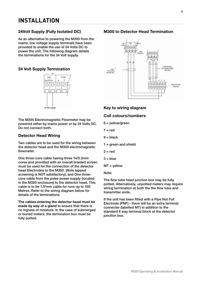
INSTALLATION24Volt Supply (Fully Isolated DC)
As an alternative to powering the M300 from the mains, low voltage supply terminals have been provided to enable the use of 24 Volts DC to power the unit. The following diagram details the terminations for the 24 Volt supply.
24 Volt Supply Termination
M300 to Detector Head Termination
Key to wiring diagram
Coil colours/numbers
6 = yellow/green
7 = red
8 = black
1 = green and shield
2 = red
3 = blue
MT = yellow
Note:
The flow tube head junction box may be fully potted. Alternatively, unpotted meters may require wiring termination at both the the flow tube and transmitter ends.
If the unit has been fitted with a Pipe Not Full Electrode (PNF) - there will be an extra terminal connecter (labelled MT) in addition to the standard 6 way terminal block at the detector junction box.
The M300 Electromagnetic Flowmeter may be powered either by mains power or by 24 Volts DC. Do not connect both.
Detector Head Wiring
Two cables are to be used for the wiring between the detector head and the M300 electromagnetic flowmeter.
One three-core cable having three 14/0.2mm cores and provided with an overall braided screen must be used for the connection of the detector head Electrodes to the M300. (Note lapped screening is NOT satisfactory), and One three-core cable from the pulse power supply (located in the M300 enclosure) to the detector head. This cable is to be 1.5²mm cable for runs up to 100 Metres. Refer to the wiring diagram below for details of the terminations.
The cables entering the detector head must be made by way of a gland to ensure that there is no ingress of moisture. In the case of submerged or buried meters, the termination box must be fully potted.
10
M300 Operating & Installation Manual
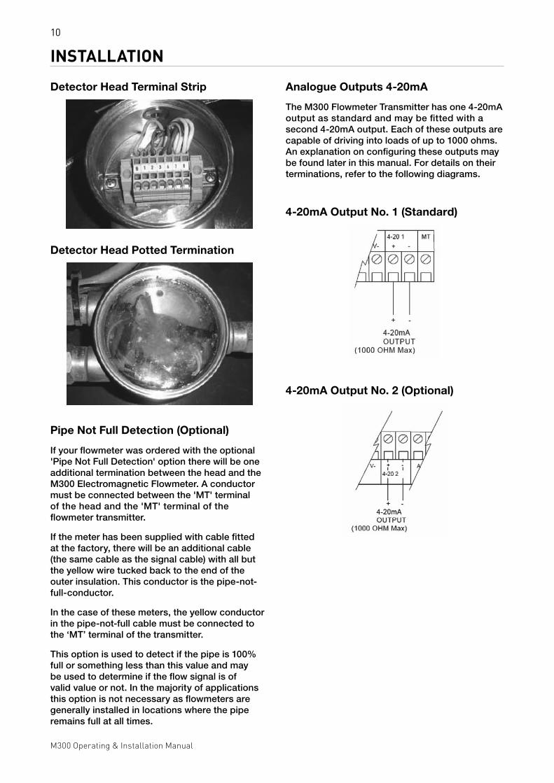
INSTALLATIONDetector Head Terminal Strip
Pipe Not Full Detection (Optional)
If your flowmeter was ordered with the optional 'Pipe Not Full Detection' option there will be one additional termination between the head and the M300 Electromagnetic Flowmeter. A conductor must be connected between the 'MT' terminal of the head and the 'MT' terminal of the flowmeter transmitter.
If the meter has been supplied with cable fitted at the factory, there will be an additional cable (the same cable as the signal cable) with all but the yellow wire tucked back to the end of the outer insulation. This conductor is the pipe-not-full-conductor.
In the case of these meters, the yellow conductor in the pipe-not-full cable must be connected to the ‘MT’ terminal of the transmitter.
This option is used to detect if the pipe is 100% full or something less than this value and may be used to determine if the flow signal is of valid value or not. In the majority of applications this option is not necessary as flowmeters are generally installed in locations where the pipe remains full at all times.
Analogue Outputs 4-20mA
The M300 Flowmeter Transmitter has one 4-20mA output as standard and may be fitted with a second 4-20mA output. Each of these outputs are capable of driving into loads of up to 1000 ohms. An explanation on configuring these outputs may be found later in this manual. For details on their terminations, refer to the following diagrams.
4-20mA Output No. 1 (Standard)
4-20mA Output No. 2 (Optional)
Detector Head Potted Termination
11
M300 Operating & Installation Manual
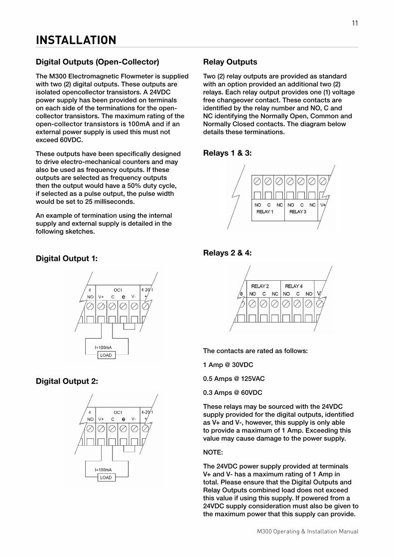
INSTALLATIONDigital Outputs (Open-Collector)
The M300 Electromagnetic Flowmeter is supplied with two (2) digital outputs. These outputs are isolated opencollector transistors. A 24VDC power supply has been provided on terminals on each side of the terminations for the open-collector transistors. The maximum rating of the open-collector transistors is 100mA and if an external power supply is used this must not exceed 60VDC.
These outputs have been specifically designed to drive electro-mechanical counters and may also be used as frequency outputs. If these outputs are selected as frequency outputs then the output would have a 50% duty cycle, if selected as a pulse output, the pulse width would be set to 25 milliseconds.
An example of termination using the internal supply and external supply is detailed in the following sketches.
Digital Output 1:
Relay Outputs
Two (2) relay outputs are provided as standard with an option provided an additional two (2) relays. Each relay output provides one (1) voltage free changeover contact. These contacts are identified by the relay number and NO, C and NC identifying the Normally Open, Common and Normally Closed contacts. The diagram below details these terminations.
Relays 1 & 3:
The contacts are rated as follows:
1 Amp @ 30VDC
0.5 Amps @ 125VAC
0.3 Amps @ 60VDC
These relays may be sourced with the 24VDC supply provided for the digital outputs, identified as V+ and V-, however, this supply is only able to provide a maximum of 1 Amp. Exceeding this value may cause damage to the power supply.
NOTE:
The 24VDC power supply provided at terminals V+ and V- has a maximum rating of 1 Amp in total. Please ensure that the Digital Outputs and Relay Outputs combined load does not exceed this value if using this supply. If powered from a 24VDC supply consideration must also be given to the maximum power that this supply can provide.
Digital Output 2:
Relays 2 & 4:

12
M300 Operating & Installation Manual
CONFIGURATIONThe M300 Electromagnetic Flowmeter is configurable via the three (3) push buttons found on the front display panel. All parameters are pre-configured in our flow laboratory prior to shipping, however parameters such as relay setpoints, etc, may be altered on site to meet your requirements.
To assist in navigating through the menus you will find a flow chart in Appendix A of this manual.
Keyboard Up Arrow Button
The 'Up Arrow Button' is used to move up through the menu system. It is also used to step through the sub¬menus and to increment the value currently being displayed once it has been selected.
Down Arrow Button
As with the Up Arrow Button, the 'Down Arrow Button’ allows movement through the menus and sub-menus only in the opposite direction. It also allows the user to decrement the currently displayed value once it has been accepted.
Tick Button
The 'Tick Button' has several functions. Depressing this button whilst in the display mode will transfer the user to the configuration menu where the user will be asked for a PIN (Personnel Identification Number). Once in the configuration menu the Tick Button is used to enter the displayed menu item or to accept the displayed numerical value. You will note that an asterisk (*) is displayed alongside the currently configured menu selection or value.
TIP: If you have entered into a menu that you do not wish to change, simply move to the item or numerical value, using the Up or Down buttons, that has the asterisk (*) along side it and again depress the Tick Button.
Exiting the Configuration Menu
To Return to the display menu simply depress both the Up and Down Arrow buttons simultaneously. The M300 will also return to the display menu automatically if no button is depressed for five minutes. For ease of configuration, if the configuration menu is re-entered within the five minutes the user will be returned the last displayed configuration menu item.
Display Menu
Forward Flow Display
The display menu enables the operator to view current information relating to the flow and configuration of the flowmeter.
The default display indicates the flow rate on the upper line of the display and the totalised units on the lower line of the display. The flow rate is displayed with the configured units following the actual flow rate (eg, 123.45 l/sec). The totalised value is displayed as a numerical value followed by the configured units. The units will also cycle to not only display the units but also the factor and the direction (eg, 12345678 kl, 12345678 x10, 12345678 FWD).
Note that the FWD is only displayed if reverse flow has been configured with the FWD
representing the forward flow totaliser.
Reverse Flow Display
Using the Down Arrow Button will display the next display item. This display would indicate the current flow rate on the upper line as for the above display and the reverse flow totaliser on the lower line. The display method is identical as for the forward flow display with the exception that the totaliser would cycle to indicate a REV representing the reverse flow totaliser. This display is only available if reverse flow has been enabled in the configuration of the M300 electromagnetic flowmeter.

13
M300 Operating & Installation Manual
CONFIGURATIONNett Totaliser Display
This display is used to display the difference between the forward flow totaliser and the reverse flow totaliser. The upper line of the display will display the words Nett Total with the lower line displaying the numerical value for nett flow. This display is only available if reverse flow and nett flow is enabled in the configuration menu.
Velocity Display
The velocity display again displays the flow rate on the upper line of the display with the lower line displaying the measured velocity based on the nominal bore of the flowmeter. The velocity is displayed in either m/sec (meters per second) or ft/sec (feet per second) and is depended on the configured units. ie if a metric value of measurement is used for indicating the flow rate (e.g. l/sec) then the display will be in m/sec however if an imperial unit is used (e.g. gpm) then the display will be in ft/sec.
Analogue Output Display
This display uses the upper and lower lines to indicate the current value of the analogue outputs. This display is in actual mA.
Digital Output Display
This screen displays the current value of the digital outputs. If the output has been configured as a frequency output then the current output value is displayed in Hz. However, if Volume/Pulse has been selected then the display simply flashes the word 'Vol/Pulse' for that output. Line one(1) is used to display output 1 whilst line two(2) displays output 2.
Relay Outputs Display
The flow rate is displayed on the upper line with the current status of the relays displayed on the lower line. The status of the relays is displayed as R#, with # representing the relay number, if the relay is currently energised and three (3) dashes if the relay is de-energised. This display is valid for relays that are configured as a status. The following example shows a display with relays one (1) and three (3) energised with relays two (2) and four (4) de-energised:
Example: 1234.56 l/sec
R1 --- R3 ---
Configuration Menu
To enter the configuration menu simply depress the Tick Button as explained earlier in this manual. Here, the user will be able to use the up and down arrow buttons to scroll through the menu items. These menu items are only accessible once a Personnel Identification Number (PIN) has been entered.
To gain access to the displayed menu item, depress the Tick Button, this will allow the use of the Up and Down Arrow buttons to scroll through the available menu items or to increment or decrement the stored numerical value.
To accept the displayed value, depress the Tick Button again which will place an asterisk (*) along side the selection and enable the Up and Down Arrow buttons to again scroll through the menu items.
To exit the configuration menu depress the Up and Down Arrow buttons simultaneously.
Following is a description of each configuration menu item:
Enter Access PIN
Use the Up and Down arrow buttons to display the Menu Access PIN. Once displayed accept the value with the tick button. If the correct PIN is entered a brief display of ‘Access Granted’ will be viewed giving access to the configuration menu otherwise a message of ‘Access Denied’ will be displayed returning the user to the display menu.
The default PIN is 121.
14
M300 Operating & Installation Manual
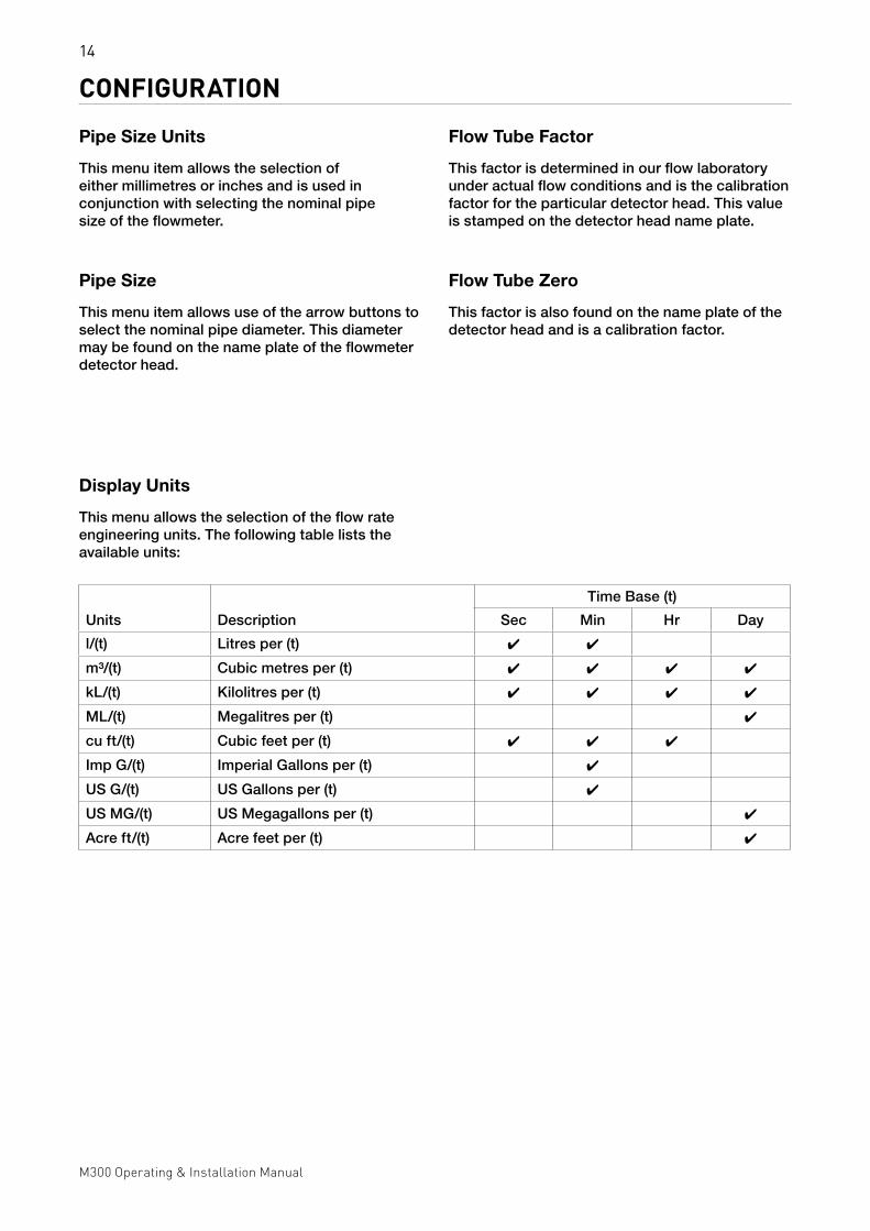
CONFIGURATIONPipe Size Units
This menu item allows the selection of either millimetres or inches and is used in conjunction with selecting the nominal pipe size of the flowmeter.
Pipe Size
This menu item allows use of the arrow buttons to select the nominal pipe diameter. This diameter may be found on the name plate of the flowmeter detector head.
Display Units
This menu allows the selection of the flow rate engineering units. The following table lists the available units:
Flow Tube Factor
This factor is determined in our flow laboratory under actual flow conditions and is the calibration factor for the particular detector head. This value is stamped on the detector head name plate.
Flow Tube Zero
This factor is also found on the name plate of the detector head and is a calibration factor.
Units Description
Time Base (t)
Sec Min Hr Day
l/(t) Litres per (t) 4 4
m³/(t) Cubic metres per (t) 4 4 4 4
kL/(t) Kilolitres per (t) 4 4 4 4
ML/(t) Megalitres per (t) 4
cu ft/(t) Cubic feet per (t) 4 4 4
Imp G/(t) Imperial Gallons per (t) 4
US G/(t) US Gallons per (t) 4
US MG/(t) US Megagallons per (t) 4
Acre ft/(t) Acre feet per (t) 4

15
M300 Operating & Installation Manual
CONFIGURATIONLow Flow Cut Off
This parameter is set as a percentage of full scale and is settable in the range of 0 to 10% in 0.1% increments. Flows less than this value are not totalised. The analogue and digital outputs are also set to zero flow.
Response Time
This parameter sets the damping or response time of the rate indicator and is entered as a numerical value. The higher the value the more damping. The dynamic range of this parameter is 2 to 100 in steps of 1.
Coil Frequency
This sets the frequency of the coil excitation. The shipping value for this parameter is 16 Hz and will be suitable for the majority of applications.
Digital Output 1
Each of the Digital Outputs (Open Collector) may be configured as either a frequency output or a pulse output. Selecting frequency output automatically sets a duty cycle of 50% for the output. (ie equal on and off time) where as selecting pulse output sets the on time to approximately 25 milliseconds.
Fullscale Frequency 1
Adjustable range is -1000 to 1000 Hz. Setting this value to a negative number allows the digital output to represent reverse flow. (eg setting this value to -500 would set the output frequency to a range of 0 to 500 Hz when flow is in the range of 0 to fullscale flow in the reverse direction. Flow in the forward direction would set the output to 0 Hz)
Volume/Pulse 1
This value allows the operator to set the number of totaliser units that each output pulse represents. This method of setting the digital output is useful for a remote electro-mechanical counter. Do not exceed 20 pulses/second.
Digital Output 2
As per Digital Output 1 but relates to Digital Output 2.
Fullscale Frequency 2
As per Fullscale Frequency 1 but relates to Digital Output 2.
Volume/Pulse 2
As per Volume/Pulse1 but relates to Digital Output 2.
Fullscale 4-20 1
This parameter is used to set the flow rate value that 20mA is to represent. 4mA always represents a flow rate of 0. Setting a negative value will enable the operator to have this output representing reverse flow.
Fullscale 4-20 2
As per Fullscale 4-20 1 but pertaining to 4-20mA output 2.
Display Digits
This menu enable the user to select between having four(4) or five(5) significant digits for the display of flow rate.

16
M300 Operating & Installation Manual
CONFIGURATIONTotaliser Units
Selects the units that the user wishes to display the totaliser. The following units are available:
Litres ................................................................ Litres
m³ ........................................................ Cubic Metres
kL................................................................. Kilolitres
ML ............................................................Megalitres
cu. ft .........................................................Cubic Feet
Imp ....................................Gallons Imperial Gallons
US Gallons .............................................. US Gallons
US MGallons .................................. US Megagallons
Acre ft ........................................................Acre Feet
Totaliser Scaling
This menu item allows the selection of a scaling factor to be applied to the totaliser units. e.g. The user may wish each count of the totaliser to represent 10 kL units. The user would therefore select kL as a totaliser unit and x10 as a scaling factor. Note that the maximum totaliser frequency must not exceed 20 Hz. The available factors are:
x 10000
x 1000
x 100
x 10
x 1
x 0.1
x 0.01
x 0.001
Zero Totaliser
This menu enables the operator the facility to reset the totalisers. Selecting 'Yes' from this menu will ask for confirmation. Pressing the Tick button will now reset the totalisers whilst pressing one of the arrow buttons will leave the totalisers unchanged. A brief message will appear on the screen stating whether or not the totalisers were cleared.
Flow Full Scale
This is a numerically entered value that is displayed in the selected display units. Once selected with the Tick button the user is able to use the Up and Down Arrow buttons to increment and decrement the numeric value until the desired full scale is displayed. Accept this value, as with all menu items, with the Tick button.
NOTE:
It is only possible to set the full scale flow rate to a value that is equivalent to a flow velocity of 0.5 to 10 Metres per second.
Fail Safe Mode
This parameter enables the operator to set the failsafe conditions of the outputs of the M300 electromagnetic flowmeter. i.e. If the M300 detects an error it will set the outputs to the nominated condition. This is true for all outputs with the exception of the system fault (refer to relays) output. This relay output, if selected, will energise on a fault.
The choices for this parameter is either ‘Low on Fail’ or ‘High on Fail’.
Reverse Flow
Enabling reverse flow will include the display of the Reverse Flow Totaliser when in the display mode. Disabling this function will cause the reverse flow totaliser not to be displayed.
Nett Flow
This menu item is only displayed if ‘Reverse Flow’ is enabled and allows the operator to select either enable or disable. Enabling nett flow will enable the Nett Flow Totaliser to be displayed in the display menu. This function is the nett value of the forward flow totaliser less the reverse flow totaliser.
17
M300 Operating & Installation Manual
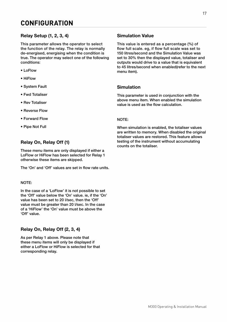
CONFIGURATIONRelay Setup (1, 2, 3, 4)
This parameter allows the operator to select the function of the relay. The relay is normally de-energised, energising when the condition is true. The operator may select one of the following conditions:
• LoFlow
• HiFlow
• System Fault
• Fwd Totaliser
• Rev Totaliser
• Reverse Flow
• Forward Flow
• Pipe Not Full
Relay On, Relay Off (1)
These menu items are only displayed if either a LoFlow or HiFlow has been selected for Relay 1 otherwise these items are skipped.
The ‘On’ and ‘Off’ values are set in flow rate units.
NOTE:
In the case of a ‘LoFlow’ it is not possible to set the ‘Off’ value below the ‘On’ value. ie, if the ‘On’ value has been set to 20 l/sec, then the ‘Off’ value must be greater than 20 l/sec. In the case of a ‘HiFlow’ the ‘On’ value must be above the ‘Off’ value.
Relay On, Relay Off (2, 3, 4)
As per Relay 1 above. Please note that these menu items will only be displayed if either a LoFlow or HiFlow is selected for that corresponding relay.
Simulation Value
This value is entered as a percentage (%) of flow full scale. eg, if flow full scale was set to 150 litres/second and the Simulation Value was set to 30% then the displayed value, totaliser and outputs would drive to a value that is equivalent to 45 litres/second when enabled(refer to the next menu item).
Simulation
This parameter is used in conjunction with the above menu item. When enabled the simulation value is used as the flow calculation.
NOTE:
When simulation is enabled, the totaliser values are written to memory. When disabled the original totaliser values are restored. This feature allows testing of the instrument without accumulating counts on the totaliser.

18
M300 Operating & Installation Manual
TROUBLESHOOTINGThe M300 Electromagnetic Flowmeter and detector head have been tested in our flow laboratory prior to shipment. However if you do experience problems please note the serial number of the instrument prior to contacting either Combined Instrument Systems Pty Ltd. The serial number may be found either on the metal label located on the detector head or on a label between the terminal cover and the display enclosure.
Display is blank
• Check the supply voltage.
• Check fuse if mains powered M300 electromagnetic flowmeter and replace if necessary.
• If using a 24V Supply, down power and wait 30 seconds, reapply supply.
• Ensure there are no short circuits across the V+ and V- terminals. Check that there is not a short circuit across the coil terminals 7 and 8.
Message 'Coil Open cct' is displayed
This message indicates that there is no current being supplied to the coil. Down power the M300 and check the wiring between the transmitter and the detector head.
Display is erratic and does not indicate zero
• Detector may not be full of liquid. Ensure pipe is full.
• Check electrode wiring between M300 electromagnetic flowmeter and the detector head.
Display does not respond to flow
• Check that the M300 is not in ‘Simulate’ mode. Removing the power for 30 seconds will automatically return the instrument to flow monitor mode.
• Check wiring between the transmitter and detector head.
• Check that there is flow in the pipe and that the pipe is full of liquid.
Flow rate indicates reverse flow
• Check orientation of wiring between M300 and detector head.
• Check flow direction arrow on detector head.
• Reverse wires in the M300 terminals 'Flow' 2 and 3.
4-20mA Output 1 or 2 operates but indicates incorrectly
• Check that load does not exceed 1000 ohms.
• Check the configuration to ensure that the output is configured correctly. (Fullscale 4-20mA 1 or 2)
4-20mA Output 2 reads zero milliamps
The second output is an option. Check to ensure that it was ordered. This option may be added if required.
Display has no back lighting
The display back lighting automatically turns off after a pre-set time, if no buttons have been depressed. Press either the up or down arrow keys to turn on the back lighting.

19
M300 Operating & Installation Manual
SPECIFICATIONDisplay ................................................... 2 Line x 16 Digit LCD display with software switched back lighting
Power Supply .........................................................................24VDC ± 10% (fully isolated and regulated DC) 95 to 260 VAC 50 Hz (Optional)
Power Consumption ................................................................................................................. Less than 25VA
Outputs ........................................................................................ 1 x 4-20mA ( 2 x 4-20mA Optional) Isolated 2 x Digital Output (Open Collector) Programmable pulse or frequency 2 x Relay Outputs ( 4 x Relay Outputs Optional)
Open Collector Rating .............................................................................................................................100mA 60VDC
Relay Rating .............................................................................................................................1 amp @ 30 VDC 0.5 amps @ 125 VAC 0.3 amps @ 60 VDC
4-20mA Max. Load ........................................................................................................................... 1000 Ohms
Measuring Range .................................................................................................Up to 10 metres per second.
Turndown .......................................................................................................>1000:1 at 10 metres per second
Input Resolution .........................................................................................................................................18 Bit
Linearity .................................................................................................................................................<0.005%
Repeatability ...........................................................................................................................................<0.05%
Accuracy ................................................ 0.2% of reading or 0.001 metres per second, whichever is greater.
Ambient Temperature .....................................................................................................................-10° to 55° C
Temperature Stability ..............................................................................................................................<0.05%
Supply Voltage Effects .......................................................................................................................Negligible
M300 to Detector Head Separation ............................................................................... Maximum 100 metres
20
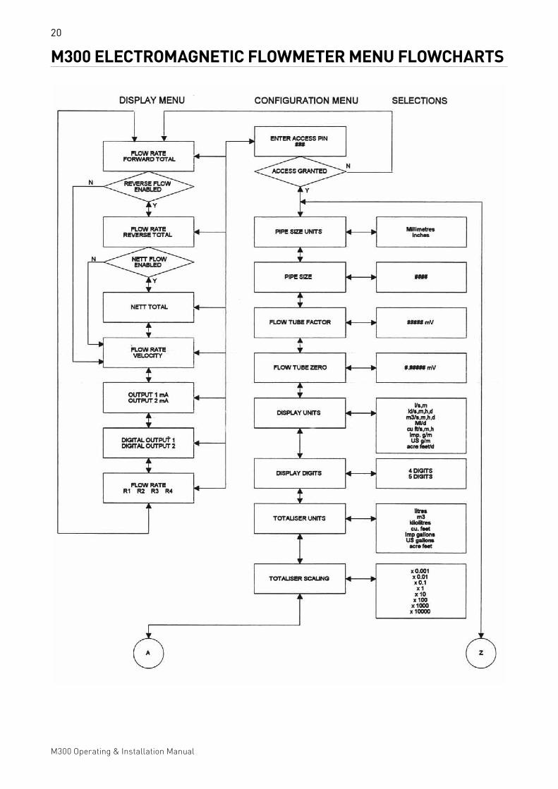
M300 Operating & Installation Manual
M300 ELECTROMAGNETIC FLOWMETER MENU FLOWCHARTS

21
M300 Operating & Installation Manual
M300 ELECTROMAGNETIC FLOWMETER MENU FLOWCHARTS

22
M300 Operating & Installation Manual
M300 ELECTROMAGNETIC FLOWMETER MENU FLOWCHARTS
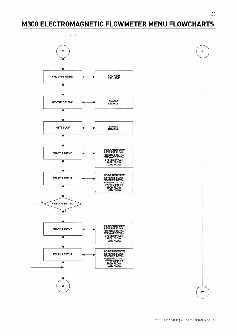
23
M300 Operating & Installation Manual
M300 ELECTROMAGNETIC FLOWMETER MENU FLOWCHARTS

24
M300 Operating & Installation Manual
M300 ELECTROMAGNETIC FLOWMETER MENU FLOWCHARTS

25
M300 Operating & Installation Manual
M300 ELECTROMAGNETIC FLOWMETER MENU FLOWCHARTS

26
M300 Operating & Installation Manual
M300 ELECTROMAGNETIC FLOWMETER ENCLOSURE DETAIL

27
M300 Operating & Installation Manual
EM DETECTOR HEAD DIMENSIONS

28
M300 Operating & Installation Manual
EM/IR2060 SERIES FABRICATED STEEL WELDED SUBMERSIBLE HOUSING

29
M300 Operating & Installation Manual
EQUIPMENT RETURNED FOR TESTING OR REPAIRYour product has been manufactured and tested with care. It should not present any problems if it is installed, maintained and operated in accordance with the manual provided. However, if you need to return your product for testing or repair, please help us by supplying all the requested information to facilitate the speedy repair and return of your equipment.
Pentair Environmental Systems will only test and repair returned products when all the required information regarding substances that have come into contact with the product, is supplied. This information is required to safeguard the health and safety of our personnel and to comply with environmental legislation.
To ensure that your product is serviced, and particularly if the product was operated with toxic, caustic, flammable, biohazard or water-endangered substances it is required that:
1. You ensure all surfaces do not contain traces of hazardous substances, and that you rinse or neutralise before shipping the product.
2. You include the Product Certificate on the following page with the product, to confirm that it is safe for us to handle and service.
If a quotation is required, an inspection charge may apply. If the quotation is accepted the inspection fee will cover the first hour of labour.
To commence testing or repairs the Product Certificate and a purchase order are required along with your product.
Please contact your local sales or service representative regarding return of goods for repair.

30
M300 Operating & Installation Manual
NOTES

31
M300 Operating & Installation Manual
PRODUCT CERTIFICATECompany Details
Company: _______________________________________________________________________________________
Address: ________________________________________________________________________________________
_________________________________________________________________________________________________
Contact: _________________________________________________________________________________________
Phone: _______________________________________ Fax: __________________________________________
Product Details
Product:_________________________________________________________________________________________
Model No.: ___________________________________ Serial No.: _____________________________________
Date Purchased: _________________________________________________________________________________
Detailed description of fault: ______________________________________________________________________
_________________________________________________________________________________________________
_________________________________________________________________________________________________
_________________________________________________________________________________________________
Safety Checks
This product has been operated with the following liquid and possible contaminants:
_________________________________________________________________________________________________
_________________________________________________________________________________________________
The liquid is:
Water-Hazardous Toxic Caustic Flammable Biohazard
We have:
Checked that it is free from these substances Flushed out and neutralised all surfaces
I confirm that there is no risk to humans or environment through any residual contaminant on this product.
Signature: __________________________________________________________ Date: ____________________

New South Wales: Ph: 1300 797 246268 Milperra Rd, Milperra, NSW 2214
Victoria: Ph: (03) 5821 404419a New Dookie Rd, Shepparton, VIC 3630
Western Australia: Ph: (08) 9477 11881/30 Oxleigh St, Malaga, WA 6090
www.aquamonix.com.au Ph: 1300 797 246