operation & maintenance manual - priorclave international
TRANSCRIPT

Priorclave Manual 2912832-EN.doc Issue Date:25 May 2006
Operation & MaintenanceManual
Front Loading Priorclavewith Vertical Power Door
Electrically Heated

2

Priorclave Manual 2912832-EN.doc Issue Date:25 May 2006
3
Introduction
Priorclave autoclaves are a range of general-purpose laboratory autoclaves intended primarily for mediapreparation, the making safe of ordinary laboratory and pathological waste and other apparatussterilisation purposes. The autoclaves are manufactured to a high standard and feature a number ofpatented innovative design features. The sophisticated TACTROL microprocessor control systemprovides a very simple method of setting even the most complex cycles. The machines have beendesigned from the outset for easy and safe operation and maintenance.
Properly looked after your autoclave should give years of valuable and trouble free service.
Priorclave Service
Serial Number:
Date of Manufacture:
Software Version:
Please quote the above when asking for parts or service:
PRIORCLAVE LIMITED
129 /131 Nathan WayWest Thamesmead Business ParkLondonSE28 0AB
Telephone: +44 (0)208-316-6620Fax: +44 (0)208-855-0616
E-mail: [email protected]: www.priorclave.co.uk
or your local distributor:

4
This Page Has Been Deliberately Left Blank

Priorclave Manual 2912832-EN.doc Issue Date:25 May 2006
5
Important Notices
Priorclave Pressure Vessels and Autoclaves are manufactured according to BS2646 Part 1 (1993). It isrecommended that the user/operator ensures that the autoclave is installed, operated, maintained andtested according to parts 2,3,4 & 5 of this standard for safe and effective use and that an adequatelogging record of operation and maintenance be established.
Before despatch from our works all Priorclaves are subjected to rigorous electrical safety tests to theappropriate standards. Should you or your contractors carry out further insulation and flash tests as partof your internal procedures please disconnect the switch mode power supply before testing. Failure to doso will result in a test failure and may lead to corruption of the microprocessor memory which cannot becovered by our warranty.
Safety
If you are unclear about any aspects of this manual, the use and operation of the autoclave or yourautoclave process please contact Priorclave or your authorised Priorclave dealer before proceeding.
Always wear gloves a facemask and adequate protective clothing when unloading an autoclave andensure that the workload does not exceed safe limits.
Priorclave are pleased provide training for operators in the use of their autoclaves at a small extra charge.
Risk of injury from powered moving parts
The power door lifting and clamping mechanism is very powerful and great caution should be exercisedwhen in the proximity of this system. Adjustments or repairs must only be carried out by fully trainedpersonnel.
Thermal Lock
The safety Thermal Lock (80oC door retention device) has been set in accordance with the load andprocedure defined in paras. 3.3.3.2.3 and 3.3.3.3 of BS2646 Part 5:1993.
The relatively light load defined under this procedure may not be appropriate to the load to be autoclavedin your Priorclave. Therefore, to ensure compliance with Health & Safety Executive Guidance Note PM73‘Safety at Autoclaves’ and to avoid possible injury you are strongly advised to have your autoclave with itsnormal working load formally validated, and the thermal lock set up accordingly by properly trainedpersonnel.
Stainless Steel Pressure Vessels.
Vessels are manufactured from grade 316L stabilised stainless steel (also known as 316 S.11 or EUgrade 1.4404), designed built and tested in accordance with BS5500 category 3 as required by BS2646Part 1. Grade 316 stainless steel is employed to reduce the corrosive effects of substances such ashydroxides and chlorine. However we recommend that the interior of the vessel is kept free of suchpotentially harmful substances and is regularly cleaned out with soft water. The use of chlorine based orother aggressive cleaners is not recommended. Exposure to such chemicals could damage the surfacefinish and the integrity of the pressure vessel and door. Care should also be taken not to routinelyintroduce such chemicals where they are used to pre-wash items that form part of the load. In such casesthe items should be thoroughly rinsed before autoclaving.
During manufacture of the pressure vessel it is necessary to use carbon steel tools and, although everyeffort is made to remove any residual internal contamination, some carbon steel pickup or traces maybecome evident during use as small particles of rust. These are not a cause for concern and will notaffect the integrity of the pressure vessel in any way. These can easily be removed with a nylon typescouring pad. As noted above the use of aggressive cleaners is not recommended.
Product Life
Due to fatigue occurring in normal use the life of all pressure vessels is finite regardless of corrosion,erosion or other damage. Using a calculation from BS3970, and assuming an average autoclaving cycletime of 2.5 hours this gives the autoclave vessel a projected fatigue life of 10,000 operating cycles. Thelifespan of the autoclave will obviously depend upon frequency of use, but for example (based on a 365day working year) if the autoclave is used two or four times per day this gives a working life of 13.6 to 6.8years respectively. Your own usage of the autoclave should be considered to determine the actuallifespan of the autoclave.

6
Cleaning
This equipment contains sensitive electrical equipment. Although designed to withstand laboratoryconditions it is not designed for wet cleaning. Cleaning this equipment by hosing down may causedamage, invalidating the warranty, and may cause an electrocution hazard.
External cleaning should be carried out with a damp cloth or with proprietary, non-abrasive cleaners.
Servicing and Maintenance of Priorclave Autoclaves
Priorclave Laboratory Autoclaves are complex pressure systems designed and built to special regulationsand as such should only be serviced or maintained by properly trained personnel. Priorclave Ltd. cannotbe held responsible for hazards or damage resulting from work carried out on the pressure system byuntrained or unauthorised personnel. If in doubt please contact Priorclave Service or your nearestauthorised dealership.
Marking
The mark applied to this autoclave is applied in relation to the EMC (Electromagnetic Compatibility)directive and the Low Voltage directive of the European Community. This indicates that this Priorclaveautoclave meets the following technical standards :
- EN50081-1Electromagnetic Compatibility. Generic Emission Standard. Residential, Commercial & Light Industry.
- EN50082-1Electromagnetic Compatibility. Generic Immunity Standard. Residential, Commercial & Light Industry.
- BS EN 61010-1: 1993Safety Requirements for Electrical Equipment for Measurement, Control and Laboratory use.
- BS EN 61010-2-041: 1996Safety Requirements for Electrical Equipment for Measurement, Control and Laboratory use; Part 2-041, Particular Requirements for Autoclaves using Steam for the treatment of Medical Materials andfor Laboratory Processes.
- EN 46001: 1997If used for the sterilisation of medical equipment within the scope of the Medical Devices Directive the
mark is applicable to this directive. If using this equipment for the sterilisation of medicalequipment your attention is drawn to the need for the consideration of the standards that may beapplicable to the type of equipment to be sterilised. If in doubt consult the manufacturer. In all casesautoclaves used for the sterilisation of medical devices must be validated in accordance with EN554before use. This product is manufactured in accordance with EN46001.
Pressure vessels
- PD5500 2000Unfired fusion welded pressure vessels
- BS2646 1996Autoclaves for sterilisation in laboratories
- BS3970 1990Sterilising and disinfecting equipment for medical products
Conformity assessment modules B1 + D of the European Pressure equipment directive have beenapplied to ensure compliance with the essential safety requirements.
A “Declaration of Conformity” in accordance with the above standards has been made and is on file at:
Priorclave Ltd.129 /131 Nathan WayWest Thamesmead Business ParkLondon SE28 0AB
Environmental Conditions
This equipment has been designed for safe operation within the following environmental conditions:- Indoor Use.- Altitude up to 2,000 M. (See Appendix B - Steam Table for special conditions affecting calibration for
operation at elevated altitudes).

Priorclave Manual 2912832-EN.doc Issue Date:25 May 2006
7
- Temperatures between 5oC and 27oC.The Tactrol control system of your Priorclave has been designed and tested to comply with thetemperature requirements of IEC 68.2.4 and BS2011 part 2.1DA, and gives satisfactory performancein accordance with those Standards at 40ºC.However, as this equipment is mounted into a compartment fitted to heat generating equipment, themaximum room temperature during autoclave operation should not exceed 27ºC.Temperatures in excess of this will cause the cold junction compensator circuits to malfunction andresult in sterilisation failure.N.B. Excessive room temperatures will, in the case of air-cooled units, also affect cooling speeds andprolong overall process times
- Maximum Relative Humidity of 85% at any temperature between 5oC and 40oC.- Mains Supply Voltage Variations not exceeding +/-10% of that shown on the Serial Plate.
Electromagnetic Interference
This equipment has been designed to comply with the requirements for immunity from electromagneticinterference under normal conditions of use. Care should be taken when siting the equipment however, toavoid interference from potential extreme sources of interference such as MR scanners or x-rayequipment.
Hazard Statement
Electrical Hazard Stickers
When this sticker has been placed on a removable panel the power mustbe switched off before the panel is removed. There may be a number ofareas behind the labelled panel that constitute an electrical shock hazard.All such panels are service access panels only and should not be removedunless there is a full understanding of the equipment.
Mechanical Hazard Sticker
When this sticker has been placed on a removable panel the power must be switched offbefore the panel is removed. There may be a number of areas behind the labelled panelthat constitute a mechanical hazard. All such panels are service access panels only andshould not be removed unless there is a full understanding of the equipment.

8
Contents
Introduction................................................................................................................................................. 3
Important Notices ....................................................................................................................................... 5
Contents ...................................................................................................................................................... 8
Layout Diagram......................................................................................................................................... 11
Control Panel Layout Diagram ................................................................................................................ 12
Operating Summary ................................................................................................................................. 13
Preparing Your Priorclave for Use for the First Time ........................................................................... 14Positioning............................................................................................................................................... 14Provision of Space and Access for Accessories..................................................................................... 14Installation ............................................................................................................................................... 14Electrical.................................................................................................................................................. 14Drainage and Exhaust Gas Ventilation ................................................................................................... 15Safety Valve ............................................................................................................................................ 17Water Supplies and Back-flow Prevention.............................................................................................. 18Initial Commissioning .............................................................................................................................. 19Full Commissioning and Performance Qualification ............................................................................... 20
Operation................................................................................................................................................... 21Opening the Pressure Door. ................................................................................................................... 214) Checking Water Level...................................................................................................................... 21Loading. .................................................................................................................................................. 22Settings. .................................................................................................................................................. 22Sterilising Temperature & Time Settings. ............................................................................................... 22Selecting other functions......................................................................................................................... 23Rapid Cooling.......................................................................................................................................... 23Automatic Free-Steaming ....................................................................................................................... 23Pulsed Freesteaming (Optional Fitting) .................................................................................................. 24Load Sensed Process Timing (Optional Fitting) ..................................................................................... 24Media Warming ....................................................................................................................................... 24Delayed Start Time ................................................................................................................................. 24Vacuum Options (Optional Fitting).......................................................................................................... 25Closing the pressure door. ...................................................................................................................... 26Starting a cycle........................................................................................................................................ 26Vent button.............................................................................................................................................. 27During the process time. ......................................................................................................................... 27Cooling. ................................................................................................................................................... 27Thermal lock............................................................................................................................................ 27Cycle complete........................................................................................................................................ 28Media Warming. ...................................................................................................................................... 28Aborting a Cycle...................................................................................................................................... 28
Operation with Options & Accessories.................................................................................................. 29Multi Program Memory Options .............................................................................................................. 29Setting Lock Keyswitch Option ............................................................................................................... 29Printer...................................................................................................................................................... 29Heater Over-Temperature Protection ..................................................................................................... 30Automatic Waterfill Option ...................................................................................................................... 31Internal Validation System ...................................................................................................................... 31Air Intake Filter ........................................................................................................................................ 31Vent Filter (Externally Mounted) ............................................................................................................. 31Vent Filter (Internally Mounted)............................................................................................................... 31Loading Trolley........................................................................................................................................ 31Adjustable Height Loading Trolley .......................................................................................................... 31
Changing Date & Time ........................................................................................................................... 32

Priorclave Manual 2912832-EN.doc Issue Date:25 May 2006
9
Warning Indicators and Fault Codes .................................................................................................. 33
Principle Components – Layout & Locations........................................................................................ 36
Maintenance.............................................................................................................................................. 37Weekly Maintenance............................................................................................................................... 37Monthly Maintenance.............................................................................................................................. 38Quarterly Maintenance............................................................................................................................ 38Annual Maintenance ............................................................................................................................... 39General Maintenance.............................................................................................................................. 39
Pipework Schematics............................................................................................................................... 41
Spares List. ............................................................................................................................................... 43
Notes ......................................................................................................................................................... 47
Appendix A - Fault Finding & Rectification Guide ................................................................................ 49
Appendix B - Steam Table ..................................................................................................................... 52
Appendix C - Wiring Diagrams................................................................................................................ 55Output Board Designations..................................................................................................................... 55
Appendix D – Specification Tables......................................................................................................... 61
Appendix E – Other Items Fitted............................................................................................................ 63Extracts from Sterling Fluid Systems (UK) Ltd Manual. ......................................................................... 65

10

Priorclave Manual 2912832-EN.doc Issue Date:25 May 2006
11
Layout Diagram
Control Panel (For detail seecontrol panel layout diagram)
Emergency Stop Button forPower Door Mechanism
Outer Door Cover
Access to Cable Ports
Hydraulic System, VacuumSystem and Steam Generator(if fitted)

12
Control Panel Layout Diagram
Key
1. Chamber Pressure Gauge2. Start Button/Indicator3. Pre-Cycle Vacuum Indicator4. Heat Indicators5. Freesteam Indicator6. Heat-up to Process Indicator7. Process Indicator8. Cooling Indicators9. Complete Indicator10. Media Warming Indicator11. Vent Button/Indicator12. Door Button/Indicator13. Freesteam Select Button/Indicator14. Load Sensed Process Timing Select
Button/Indicator (optional)15. Cooling Select Button/Indicator16. Media Warming Select Button/Indicator17. Vacuum Select Button/Indicator (optional)18. Temperature Display/Setting19. Timer Display/Setting20. Thermal Lock Key-switch21. Door Control System Fault Indicator22. Door Cover Unlocked Indicator23. Door Mechanism Emergency Stop Button
Optional Fittings
24. Printer25. 5/10 Program Memory Buttons/Indicators26. Setting Lock Key-switch
25
26
24
19
21
18 20
7
13
16
22
14
17
4
5
6
12
15
2
9
10
8
3
1
11
23

Priorclave Manual 2912832-EN.doc Issue Date:25 May 2006
13
Operating Summary
N.B. Before proceeding please check the specification sheet included with this manual to establish whichoptions and accessories, if any, are fitted to your Priorclave. This will determine whether you will need toread the instructions for these options later in this manual.
Check the electricity and water supplies are ON.
Press and release the ‘Door’ button on the control panel. There will be a bleep and the message ‘hoLd’will be displayed in the timer display. Wait for a short time until the timer display returns to normal, there isanother bleep and the ‘Door’ indicator illuminates.
1) Check that the pressure gauge is reading zero and you may now press and release the ‘Door’ buttonto start the door opening sequence. The outer door cover must be kept closed or the door will notoperate.
2) The door will now go through its opening sequence behind the outer cover.
3) Once the door has fully opened, press and release the ‘Door’ button again to release the outer coverlocking solenoid. When the cover is ready to open the Outer Door Locked control panel LED willilluminate. Do NOT try to force the outer cover open when locked.
4) Top up with water if necessary to just below the level of the weir or if an automatic water-fill system isfitted, allow the autoclave to fill automatically to this level.
5) Load the autoclave with baskets or containers.
6) Set the temperature as required using the up/down keys.
7) Set the process time as required using the up/down keys.
8) Set / select other functions i.e. free-steam, rapid cooling etc., as required and if fitted.
9) Carefully close the outer door cover.
10) Press and release the ‘Door’ button to start the door closing sequence. The door will now lift intoplace and lock behind the outer door cover.
11) Wait a few seconds for the ‘Start’ indicator to illuminate, and press the ‘Start’ button to begin thecycle.
Cycle Abort and Thermal Lock Override
Aborting a cycle
To abort the cycle at any stage press the ‘Start’ Button.
Thermal Lock Override
First abort the cycle as above. After checking that there is no pressure within the autoclave turn thethermal lock key to the right and hold it there. Then press the ‘Door’ button once, keeping the thermallock key held over. Wait during the ‘hoLd’ display until the ‘Door’ indicator illuminates. Keep the key heldand press the ‘Door’ button to unlock the door. The key-switch can now be released. If the key isreleased at any stage the procedure must be repeated to open the door and reset the display.

14
!
Preparing Your Priorclave for Use for the First Time
Unpack the autoclave and check against the delivery note that all items ordered have been delivered.
Any shortages or damage must be reported to Priorclave Limited within 7 days of delivery.
PositioningWhen positioning the autoclave consideration should be given to proper access for servicing andmaintenance purposes. Space must also be allowed for pipework and electrical connections.
The autoclave has castors fitted to allow positioning and should ideally be positioned within easy reach ofa suitable isolatable electrical supply and drain. See Installation.
All autoclaves during their process cycle will release steam and heat, and this should be taken intoconsideration when choosing a site in your laboratory in which to install your autoclave
Provision of Space and Access for AccessoriesAutoclaves with drain condensers
Drain condensers are fitted to the rear panel of front loading autoclaves, and require sufficient space tobe allowed for pipework to enter the condenser. Drain condensers for top loading autoclaves are suppliedas separate units and consideration should be given to where the condenser is to be located as it may notbe practical to site this to the rear of the autoclave. Drain condensers may operate at high temperaturedepending on final settings, and effectiveness of the cooling water supply. Consideration should be givento heat hazards when deciding on the location of a condenser.
When all pipework is complete the condenser will occupy a space of approximately 300 x 500mm.
Autoclaves with exhaust filtration
The location of exhaust filters will vary according to the individual specification of the autoclave. In thecase of rectangular vessel autoclave the filter is usually fitted inside the autoclave vessel, and in suchcases further consideration of the filter location is not necessary.
In the case of top loading and smaller front loading autoclaves it is not possible to locate the filter insidethe vessel due to space constraints and limitations of currently available filter mediums. It is thennecessary for the filter to be located in a separate pressure vessel outside of the autoclave. Externalexhaust filter housings are located to the upper rear of the autoclave, and protrude from the left-hand sideas viewed from the front of the autoclave by up to 200mm. In normal circumstances the filter housing willfit into the 300mm space already provided to the rear of the autoclave. Special arrangements for thelocation of exhaust filters can be made on request.
It is normal for exhaust filter housing to reach temperatures in excess of 100oC, therefore considerationshould be given to heat hazards when deciding on the location of an autoclave with an exhaust filter.Provision should be made to protect personnel from heat hazards whist maintaining adequate access forfilter replacement. A minimum height of 500mm is required above the top of the filter housing forreplacement of the filter.
Provision should be made to guard or insulate pipes exiting the autoclave where these may present aheat hazard.
InstallationElectricalTo connect your Priorclave to the power supply simply connect a suitable cable from your isolator to theisolator on the back of the autoclave. In many cases the isolator will already be connected via a suitablecable and plug. In these cases connect this plug to the matching socket which should be available onyour wall.
The electrical supply as per the required specification should be terminated in an industrial socket to BS4343 (IEC/EN 60309-2) which should be located on the wall to the rear of the autoclave within 2 metres ofthe connection to the autoclave. The socket should be of the 3P + N & E type rated at 16, 32 or 63 Amps

Priorclave Manual 2912832-EN.doc Issue Date:25 May 2006
15
dependent upon the autoclave specification. If not provided as part of the industrial socket a suitablemeans of isolation is required to be located in a position where it can easily be accessed to terminatepower to the autoclave when necessary. The socket and isolator should be installed and tested inaccordance with the IEEE Wiring Regulations Sixteenth Edition. If existing electrical services from aprevious installation are used this should be examined and tested in accordance with the aboveregulations by a qualified electrician. If installation is ordered the autoclave is supplied with a plug suitablefor connecting to a socket of the above specification. This is connected by a 3 metre flexible cable to therear of the autoclave. It is important to note that the earth bonding of the plug and cable arrangement istested before dispatch from the factory, if it is necessary to remove the plug to make alternativearrangements for connection the installation will require re-testing.
If a cable and plug are not fitted then your Priorclave can be wired as shown in the diagram below.
N.B. If a cable has been fitted to the autoclave there should be no need for any further electricalinstallation.
The power supply should be a 3 phase and neutral isolated supply, rated at 15 Amps per phase andconnected to the isolator as in diagram (B). Sufficient length of cable should be used to allow theautoclave to be pulled out and worked on from the back if necessary. The cable used to the earth line andneutral feeds should be capable of carrying the per phase amperage of the supply. The neutral line mustbe nominally at earth potential and must NOT be fused. This equipment must be earthed.
Drainage and Exhaust Gas VentilationThe various inlets and outlets are situated at the back of the autoclave and are labelled with theirindividual functions. Within the space constraints of the autoclave cabinet, where possible drains andinlets have been combined to reduce the number of connections required. Please read the followingguidance before proceeding with connection to drains and water supplies.
General
Autoclaves used for processing laboratory waste must be provided with a drainage connection asdescribed below. This is a requirement of British Standard 2646. A connection will also be required if theautoclave is fitted with any freesteaming or vacuum options as significant amounts of steam will bereleased from the autoclave at different stages of the cycle. The hazard groups below are as defined bythe Advisory Committee on Dangerous pathogens as published in Categorisation of Pathogens Accordingto Hazard and Categories of Containment.
Extract from BS2646 Part 2 1990
7.2 Drainage system
“The drainage system from the autoclave should prevent dispersion of splashes and steam into theworking area. For autoclaves designed for a make-safe process, discharge should be directed to a sealeddischarge system; the system should lead by direct connection to a building drain or catchment tank.
An open tun dish is not suitable for the discharge line of a laboratory autoclave, which is to be used for amake-safe process.
The sealed discharge system should be vented to a high level by a pipe not less than 30mm diameter.The vent pipe should be directed outside the building. Steam should not emit from the vent pipe.”
From Scope of BS2646
“This Part of BS2646 gives guidance on the planning for, and installation in laboratories of, autoclaves forthe sterilisation of materials and equipment, including those which may be contaminated with organismscategorised as Hazard Groups 1, 2 or 3. It does not cover the installation of autoclaves used for material

16
contaminated with organisms categorised as Hazard Group 4, for which complete containment ofcondensate is considered to be essential.”
A further comment in a later clause adds…
“In certain circumstances, e.g. special research activities involving high concentration and/or largevolumes of agents in Hazard group 3, additional safeguards may be required. The advice of the Health
and Safety Executive should be sought in each such case. Further containment than that detailed above,(Generally as described below in this case.) filtration or heat treatment of discharge is only necessary forautoclaves used to process material contaminated with organisms in Hazard Group 4.”
In case of any doubt the full text of BS2646 should be consulted.
The autoclave requires a sealed connection to a trapped building drain. This drain should be providedwith a heat resistant vent pipe of 30mm minimum diameter vented freely to atmosphere at a safe locationoutside the building. Care must be taken in the design of the drainage connection to ensure that an airbreak will be preserved at all times to prevent the autoclave from sucking water back from the drain as itcools. Excessive back pressure produced by restrictions in the vent pipe may impair the function of theautoclave. Note that at some stages of the cycle the autoclave may discharge steam under pressure, andif vent flow is inadequate steam may be forced to exit via other interconnected drains.
If possible it is always advisable to connect the autoclave to a drain to cut down on the amount of steamdischarged into the laboratory. A compression fitting should be incorporated in the drainpipe in an easilyaccessible location to enable easy disconnection for maintenance purposes.
All drain piping should head downward towards the drain to prevent water collecting in the pipe.
Attention should be paid to the material of the vent pipe as steam and water discharged from theautoclave can be at temperatures in excess of 100oC. In the case of autoclaves with pulsed freesteaming,vacuum drying, and vacuum cooling it may be advisable to fit a drain condenser to cool the autoclavedischarge, and condense the steam.
The drain and vent pipe should be in place prior to commencement of installation by Priorclave. It willthen be possible to make connections from the autoclave directly into the drainage services provided.
The point where connection from the autoclave to thedrainage system is made should be within 2 metresof the autoclave. The location of individualconnections is shown on the installation drawings.
Multiple autoclaves in a single location
If more than one autoclave is to be installed at asingle location then the services described need tobe provided for each autoclave. If more than oneautoclave is utilising the same drain and/or ventarrangement, then there may be problems due tocross flow of effluent between autoclaves. Forexample if one autoclave is being loaded by the

Priorclave Manual 2912832-EN.doc Issue Date:25 May 2006
17
operator whilst the other is in the freesteaming stage, then it may be possible for hot air and steam beingdischarged by one autoclave to enter the other presenting a hazard to the operator. If common servicesare to be shared it is essential that these are sufficiently isolated from one another to prevent cross flow.
Safety ValveAll autoclaves are fitted with an over pressure safety valve to protect the autoclave from overpressurisation. This valve will emit large volumes of steam in the event of the autoclave exceeding itsmaximum working pressure. It is a requirement during safety valve function, and routine testing to be ableto see and hear if the safety valve has operated. It is Priorclave’s preferred policy to direct the safetyvalve outlet to discharge to the floor at the rear of the autoclave. Some establishments prefer safety valveoutlets to be piped to a high level outside the building. If this is required the pipework for this should beprovided, and terminated within 1 metre of the safety valve discharge point at the rear of the autoclave.All safety valve pipework should be DN25. A drainage point should be provided at the lowest point of thesafety valve pipework. This should be a pipe of approximately 6mm ID, and should be positioned todischarge into a suitable receptacle to the rear of the autoclave. No valve should be fitted to this drainagepoint thereby allowing it to act as a “tell tale” indicating if the safety valve is operating. Under nocircumstances must any isolating valve be fitted to the safety valve pipework. External pipework must be
designed to be self draining, and under no circumstances should water be able to collect in a trap, whichcould freeze in cold weather. See also BS3970 part 1 1990, sections 7.2.4 and 7.2.5.
Autoclaves with water tanks and drip trays
A separate drain is required for the connection of water tank and drip tray outlets. This may be a commonconnection to the same drainage system as above, but in such cases a sufficient level of isolation (suchas a deep trap) is required to prevent the cross flow of steam between the drains. The drip tray and watertank overflow can be connected to an open tundish if desired. This has the advantage of making anydischarge from the overflow visible, which is in accordance with water bylaws.

18
Water Supplies and Back-flow PreventionThe Water Supply (Water Fittings) regulations 1999
Note: The fluid categories below relate only to the above regulations, and are in no way connected withthe containment categories previously discussed with reference to drainage and containment ofpathogens.
It is mandatory that the completed installation complies with the Water Supply (Water Fittings) regulations1999 – SI No 1148. This will be dependent on factors outside of the autoclave such as the layout of thewater supply provided. The location and usage of the autoclave will determine the fluid category for whichback-flow prevention measures are to be taken, however it is suggested in the guidance notes to theabove regulations that all laboratories in industrial and commercial installations are considered category5. Prevention measures suitable for fluids in this category may therefore need to be considered.
The back-flow prevention measures already provided within the autoclave are as follows:
Autoclaves with Automatic Water Fill Systems and Liquid Ring Vacuum Pumps
Water is fed to the autoclave vessel and vacuum pump via a header tank with air gap and circularoverflow, which is classified type AF. This alone will provide back-flow prevention measures suitable forfluids up to category 4. Provided that the supply to the autoclave is delivered via a header tank withsimilar prevention means elsewhere in the building the installation will form an air gap with interposedcistern of type AUK, which is suitable for fluids up to category 5. Separate header tanks for each of thesefunctions are provided allowing the automatic water fill tank to be fed from a treated water supply, and thevacuum pump to be fed from an untreated supply to economize on the use of treated water if required.Considerations for the use of treated water are discussed later.
Autoclaves with Water Cooled Condensers and Water Jackets
For installations falling into lower fluid categories it will be possible to use mechanical means to preventback flow such as a verifiable single, or non-verifiable double check valve. For higher fluid categoriesnon-mechanical means such as break tanks must be applied. Due to the pressure and flow rates requiredfor the condensers to work effectively it is not practical to provide header tanks locally to the autoclave.The condenser and or jacket will work more effectively when more cooling water flow is achieved acrossthe condenser, therefore the more head of water that can be provided the better.
Arrangements to meet the back-flow prevention requirements will therefore need to be made at a highlevel. If a water feed from a suitable header tank arrangement to satisfy the regulations cannot beprovided it will be necessary to take other measure such as the provision of a break tank and pumparrangement locally to the autoclave.
General
All water supplies should be terminated on the wall to the rear of the autoclave, at a point within onemetre of the point of connection to the autoclave. (See installation drawing.)
In hard water areas it will be necessary to use softened water for the supplies to the autoclave to preventscaling of the autoclave vessel and heating elements. Hard water can also reduce the life span of liquidring vacuum pumps and drain condensers when fitted, however the cost of supplying treated water tothese may be considered prohibitive, and if this is the case, then a second water supply will be required. Ifthe autoclave is to be connected to a distilled or de-mineralised water supply care should be taken toguard against the corrosion of copper pipework due to excessive purity of the water supply. The waterlevel detection system of most autoclaves is operated on a conductivity-based system, due to this feedwater requires a minimum conductivity level of 10-15 micro Seimens.
Autoclaves with an automatic water fill system require a DN15 water supply terminated in an appliancetap with a suitable connector for a standard appliance hose.
Autoclaves with liquid ring vacuum pumps require a further DN15 water supply terminated in a 1/2”BSP/DN15 compression fitting.
Autoclaves with drain condensers require a water supply for the condenser. The size of connection forthis will vary depending upon the specification for the individual autoclave. In most cases a supply inDN20 will suffice, however in some cases expanding up from a DN15 supply locally in the area of theautoclave may not provide a sufficient water flow to reduce the autoclave discharge to the desiredtemperature.
!

Priorclave Manual 2912832-EN.doc Issue Date:25 May 2006
19
Consideration should be given to the discharge from the Vent and Safety Valve outlets, whichshould be directed in such a way as to not cause a hazard. This will be determined by the locationof the autoclave.
Initial CommissioningPriorclave Autoclaves are given a full operational test before leaving the factory and as such arrive readyfor immediate use after installation. It is advisable however to run a simple cycle with the autoclave emptybefore processing a working load to check that no problems have arisen during transport.
If commissioning has been ordered with the autoclave this will be carried out by a Priorclave technicianotherwise follow this simple procedure to check the operation of your Priorclave.
1) Check the electricity supply is ON and that, if required, the water supply is connected and on.
2) Switch on the power at the isolator at the back of the autoclave (for position see diagrams above). Allindicators will light momentarily and a sounder will bleep. This enables the indicators to be checked.The low water indicator should now be lit.
3) As you are powering up the autoclave for the first time, the autoclave will be in a low water conditionand the error code F004 will show in the temperature display. You may ignore this at this stage asopening the autoclave and filling it with water will reset this error.
4) Press and release the ‘Door’ button on the control panel. There will be a bleep. Wait for a short time(around 20 seconds)until there is another bleep and the ‘Door’ indicator illuminates.
5) Check that the pressure gauge is reading zero and you may now press and release the ‘Door’ buttonto start the door opening sequence. The outer door cover must be kept closed or the door will notoperate.
6) The door will now go through its opening sequence behind the outer cover.
7) Once the door has fully opened, press and release the ‘Door’ button again to release the outer coverlocking solenoid. When the cover is ready to open the Outer Door Locked control panel LED willilluminate. Do NOT try to force the outer cover open when locked.
8) The autoclave uses immersion heaters in a reservoir of water behind the weir at the bottom of theautoclave to raise steam. The heater is protected from boiling dry by a low water cut-out. If the waterlevel falls below the sensor the autoclave shuts down, the low water warning indicator is lit and faultcode F004 is shown in the temperature display.
9) In hard water areas distilled water must be used to prevent scale from forming in the autoclave; whenthe autoclave is new, however, some tap water may need to be added until the low water lamp isextinguished as the low water cut out is operated by the water’s conductivity.
10) The reservoir should be filled with water to a level just below the weir. If an automatic water-fill systemis fitted to the autoclave this will activate once the door has been opened. Water will be allowed intothe autoclave until the correct level is sensed by the float switch at the front of the autoclave.
11) Set the temperature to 121oC and the process time to 15 minutes using the arrows under thedisplays.
12) Carefully close the outer door cover.
13) Press and release the ‘Door’ button to start the door closing sequence. The door will now lift intoplace and lock behind the outer door cover.
14) Wait a few seconds for the ‘Start’ indicator to illuminate, and press the ‘Start’ button to begin thecycle.
15) During the cycle, check that there are no problems during heat-up and process.
Following successful completion of the commissioning cycle your Priorclave is ready to process its firstworking load.
Please refer to the Operation section later in this manual before running your first working load as thisgives further details on operation of the autoclave and on the control options which may be fitted
If you experience any problems during this procedure please contact Priorclave service or your localagent.
!

20
Full Commissioning and Performance QualificationIf you are having the unit commissioned by a Priorclave technician this will be a simple matter of checkingfor correct installation, checking that all functions are operating correctly, and familiarising you with theautoclave. There are, however some benefits that can be gained from having your Priorclavecommissioned to suit your particular loads and requirements. Some examples of settings that can beoptimised during commissioning, and the advantages these can provide are listed below.
- Establishing optimum freesteam temperatures for effective air displacement.- Establishing optimum freesteam time for effective air displacement, whilst eliminating unnecessary
time and energy consumption.- Establishing optimum process time and temperature to ensure complete sterilisation, whilst
maintaining minimum cycle time and energy consumption.- Setting thermal lock release temperature to suit your particular load, to eliminate unnecessary cooling
time whilst ensuring safety.
If you feel that any, or all of the above would be of use to you then please contact Priorclave Service.

Priorclave Manual 2912832-EN.doc Issue Date:25 May 2006
21
Operation
Before using your Priorclave for the first time check that the circuit breakers and isolator (at the back ofthe autoclave) are switched on. If your autoclave is fitted with vacuum options, or a steam and WaterJacket also ensure that the water supply is switched on.
Before proceeding please check the specification sheet at the front of this manual to establish whichoptions and accessories, if any, are fitted to your Priorclave. This will determine whether you will need toread the instructions for these options later in this manual.
Opening the Pressure Door.1) Switch on the power at the isolator. All indicators will light momentarily and a sounder will bleep. This
is to enable the indicators to be checked. The start indicator should now be lit. Press and release thedoor button, which will bleep, and wait for a short time (about 20 seconds) until the door indicatorilluminates and the sounder bleeps again. During the waiting time the temperature display will showhoLd, confirming that the autoclave is waiting during its safety delay. Check that the pressure gaugeis reading zero and you may now press and release the door button to start the door openingsequence. The outer door cover must be kept closed or the door will not operate. (The vent buttonwill light when the door button is pressed and remain lit after the door is opened.)
2) The door will now go through its opening sequence behind the outer cover.
Do NOT try to force the outer cover open when locked as this will damage the locking mechanismand make the whole door system inactive.
If at any point the Red LED above the control panel is lit then there has been a failure in the dooropening control system. Do not attempt to rectify this yourself. Please call Priorclave service or yourlocal service agent immediately.
3) Once the door has fully opened, press and release the door button again to release the outer coverlocking solenoid. Once the locking bolt is released the green LED on the control panel will lightshowing that the cover is ready to open. This will release for a short period only (5-10 seconds) toprotect the locking solenoid. If the outer cover is not released in time then pressing the door buttonagain will release it.
Care should be taken when opening the cover as steam may be released. Heatproof gloves and aface-shield should always be worn when unloading autoclaves.
4) Checking Water Level.The autoclave uses immersion heaters in a reservoir of water behind the vessel weir plate to raisesteam. The heaters are protected from boiling dry by a low water cut-out. If the water level falls belowthe sensor the autoclave shuts down, the low water warning is lit and fault code F004 is shown in thetemperature display.
The reservoir should be filled with water to a level just below the weir at the front of the autoclave.
If your autoclave is fitted with an automatic water-filling system then the autoclave will begin to fill withwater to the correct water level as soon as the lid is opened.
In hard water areas softened water must be used to prevent scale from forming in the autoclave. Onmanually filled autoclaves distilled water can be used but when the autoclave is new, some tap watermay need to be added until the low water warning goes out as the low water cut-out is operated bythe water’s conductivity.
NOTE: Great care should be taken to ensure that the insulated part of the low water sensor isclean (see diagram in Maintenance section) as a build up of contamination here will preventthe low water cut-out from working and could lead to heater damage.
ATTENTION
!
!
!

22
Loading.5) The autoclave can now be loaded with the items to be sterilised either directly onto the shelves, in
baskets, or watertight discard containers in the case of waste loads which may leak liquids whenautoclaved.
If fitted the centre shelf is retained at the back to prevent tipping when extended and is preventedfrom being accidentally removed by pulling forwards. To remove this shelf lift it at the front and gentlypush it back until the anti-tip catches are released from the back of the runners.
Care should be taken when loading the baskets or containers not to pack them too tightly withmaterial. Ample room must be allowed for steam to penetrate the load properly or full sterilisation willnot be achieved. When using autoclave bags these should be left open with the top of the bag rolledoutwards, exposing the load to the steam inside the pressure vessel. Care should also be taken thatthe contents of bags and containers are not able to spill over into the body of the autoclave vessel.Any such spillage could block pipes and valves and will not be covered by the warranty.
Tests have shown that the depth of un-perforated discard containers should be no greater than180mm (7”) for effective air displacement from the load. Suitable containers are available fromPriorclave.
Settings.6) Once the autoclave has been satisfactorily loaded the controls should be set for the process cycle
that you require.
If your autoclave has a setting lock fitted this must be set to position 3.
Sterilising Temperature & Time Settings.The Medical Research Council has recommended the following temperatures and times as beingsufficient for complete sterilisation in autoclaves:
126oC for 10 minutes.121oC for 15 minutes.115oC for 30 minutes.
These temperatures and times relate of course to load temperatures and the aim in setting a cycleshould be to achieve one of the above criteria in the coldest part of the load. Some loads however aresensitive to elevated temperatures for prolonged periods, making full achievement of the aboveimpractical. However the disinfection of such loads after a short cycle, without necessarily reachingfull Sterilising Temperature, is usually sufficient for most purposes.
Should you require a more precise method then the optional Load Sensed Process Timing may beof assistance for certain load types. If your autoclave is fitted with this option please refer to theinstructions later in this manual.
Since there is a time and temperature ‘lag’ between the temperature controller probe and the load, thisshould be compensated for either by increasing temperature or process time, or by including in thecycle a period of free steaming with the vent open at 100oC. This can be achieved by pressing in thevent button manually and releasing it manually. Alternatively, the Automatic Freesteaming functioncan carry out this process automatically if the option is selected.
If you have an interest in any of the options mentioned above, which can quite easily be retrofitted;please contact Priorclave Technical Services Department. - (0)20 8316 6620
In conclusion, when setting up the autoclaving cycle a large safety margin should be allowed withinthe settings.
Performance Qualification testing can determine more precise settings.
Setting the process time.The process timer can be set to a time up to 999 minutes. Simply pressing thetime up/down buttons sets the time required. The set time is displayed until the settemperature is reached, then the process time begins counting down to zero inincrements of one minute.
ATTENTION

Priorclave Manual 2912832-EN.doc Issue Date:25 May 2006
23
Setting process temperature.Pressing either the up or down button momentarily causes the current set temperature to bedisplayed. Subsequent use of the up/down buttons changes the set temperature. If no keys arepressed for a short time, the display returns to showing the current chamber temperature.
Selecting other functions.The function select keys may be used to switch the Media Warming Option, and optional functionssuch as Rapid Cooling, on or off at any time other than when a cycle is running. An indicatorilluminates to show that a function has been selected. If Automatic Timed Freesteaming, VacuumOptions or Load Sensed Process Timing are not fitted pressing the appropriate key will result in avisual and audible fault being signalled and the function will not be selected.
Possible selections are:
Rapid CoolingThe autoclave is cooled by powerful fans below the vessel, which direct cool air over it.
If selected by using the cooling button, the cooling fan will switch on automatically during the coolingstage of the cycle. There are three possible settings for rapid cooling, and these operate as follows:
Off - No indicators lit.The cooling fan does not operate at all during the cycle.
Immediate start - Left hand indicator lit. - 1 press of the cooling button.The cooling fan starts as soon as the cooling stage is reached.
Delayed start - Both indicators lit. - 2 presses of the cooling button.The cooling fan starts after the autoclave chamber has cooled to 100oC. Thissetting is useful when autoclaving some fluid loads, as bringing the coolingfan on at temperatures above 100oC may reduce the chamber pressure toorapidly, causing the load to boil.
In both cases the fan will switch off automatically when the cycle has reached the completestage.
Automatic Free-SteamingWhat is freesteaming?
Incorporating a period of freesteaming into a cycle can improve air removal in difficult loads and/orreduce temperature lag between the load and the autoclave, reducing process time at highertemperatures. Freesteaming introduces a stage during heating up to process temperature, when asolenoid valve at the rear of the autoclave is opened for a pre-set time. The valve opens at afactory set temperature of just above 100oC and is held open for the time set as detailed below.During this time steam is being generated in the chamber in large volumes andthis creates turbulence as it passes through the load before escaping throughthe valve. It is this turbulence that can assist with air removal.
Setting the freesteam time.
If freesteaming is required this is selected by pressing the freesteam button.The indicator lights up to show that freesteaming is selected. The time display will now flashindicating that the freesteam time, not the process time, is currently being displayed. The freesteamtime can now be set (in minutes) using the up/down buttons. If no further changes are made for ashort time the display stops flashing, and reverts to showing process time. If you wish to check thefreesteam time or make further changes then freesteaming should be deselected, then reselected.
Freesteam temperature setting.
If your autoclave is equipped with timed freesteaming, this will commence at a temperature slightlyabove 100oC, which has been set at the time of manufacture. If required qualified personnel mayincrease this temperature, and the turbulence caused by the escaping steam pressure can furtherassist with air removal. It is desirable however to connect the autoclave to a drain and vent pipe (asdescribed in Installation), as the release of pressurised steam into the laboratory should beavoided.

24
Pulsed Freesteaming (Optional Fitting)With certain loads and in certain situations the efficiency of the freesteaming process can beimproved by pulsing. If this option is fitted to your autoclave then freesteaming commences asdescribed above but at a higher temperature (usually about 112oC). Instead of remaining open forthe entire freesteaming period the vent valve shuts off at a lower temperature (usually about107oC). The autoclave then heats up again to the temperature at which the vent valve opens again.The autoclave will continue this cycle for the time set when selecting freesteaming. This continualpulsing of steam out of the autoclave creates considerable turbulence within the autoclave, helpingto draw trapped air out of the load.
All Priorclaves fitted with freesteaming can be configured for pulsing by qualified personnel,however connection to a drain and vent pipe as described in Installation is essential.
Load Sensed Process Timing (Optional Fitting)Function
If this option is fitted, the autoclave will be provided with an additional thermocouple. This is aPTFE coated stainless steel armoured probe, which can be positioned in the load, ideally in thecoolest part. When this option is selected, the autoclave will heat to the set chamber temperatureas normal. However, when the set temperature is reached the process time will not begin to countdown until the load temperature, as sensed by the additional thermocouple, reaches a temperaturejust below the set chamber temperature. The cycle will then proceed in the usual manner.
Purpose
The use of load sensed process timing can greatly assist with the sterilisation of certain types ofdifficult dense loads, such as large baskets of bottle caps, pipette tips or animal feed, by ensuringthat the load reaches set temperature. The system is also very effective for bagged plastic wasteloads, however as these tend to melt down around the probe, consumption of probes can be high.For this type of use load validation may prove to be more successful and economical in the longterm.
Displaying Load Sense Probe Temperature
For programs with load sensed process timing selected/enabled, pressing the load sense buttonwhen a cycle is running, or the key-switch (if fitted) is not in position 3 causes the current loadprobe temperature to be displayed in the temperature display. The display flashes whilst the loadprobe temperature is being displayed.
Load Sense Probe Positioning
The probe should be positioned in what is anticipated to be the slowest part of the load to heat forexample the centre of a large densely packed load, or the largest of a group of filled bottles. This isimportant, as there may be large variations in temperature distribution throughout the load.
NOTE: Temperature variations can be reduced by the use of timed free steaming (seeabove).
Load Sense Thermocouples
The load sensed process timing option utilises a thermocouple connected directly to the mainprocessor board via a plug and socket connector for ease of replacement.
Replacement thermocouples are available from Priorclave.
See Maintenance for details on thermocouple replacement.
Media WarmingIf this highly useful feature is selected the autoclave will cool to a factory pre-set temperature of45oC. The temperature will then cycle between approximately 45o to 55oC until the door is opened.This allows, for example, nutrient media to be held as a liquid until it is needed.
Delayed Start TimeThe autoclave can be set before a cycle to start at a pre-set time.
To access this settings turn & hold the thermal lock key in the override position. Press the time upor down keys. Release the thermal lock key. 1 is displayed on the temperature display, by default 0will displayed on the time display. The temperature display now shows the number of a list of

Priorclave Manual 2912832-EN.doc Issue Date:25 May 2006
25
operating parameters, the value for the parameter is shown in the time display. Scroll through thelist of available parameters using the temperature up/down keys.
After no keys are pressed for eight seconds the display returns to normal.
The function of these settings is as follows:
Temp.
Display
Time
Display
Function Action
1 0-24 Delayed Start Time Hour + Enter required Start time hour (24 hourclock)
2 0-60 Delayed Start time Minute + Enter required Start time minute
3 0/1 Start Delay Select On/Off + 0= OFF1= ON
+ The time is set in real time, therefore the clock has to be correctly set for this to work properly.
After one delayed start operation, delayed start automatically switches off, and the autoclavereturns to normal operation.
For instructions for setting the clock time and for other operator settings please refer to the sectionChanging Date & Time later in this manual.
Vacuum Options (Optional Fitting)N.B. It is strongly recommended that to achieve optimum performance from Priorclaves fitted withvacuum options that commissioning and/or load validation tests are carried out by a trainedPriorclave engineer. If no particular programs have been specified your autoclave will be factory setwith the following programs:
- Program 1: Non vacuum Cycle- Program 2: Pre-Cycle Vacuum and Vacuum Cooling- Program 3: Pre-Cycle Vacuum and Vacuum Drying (if specified, otherwise as program
2)
Pre-Cycle Vacuum
The pre-cycle vacuum is selected using the function select key on the control panel. With the left-hand indicator lit the Pre-Cycle Vacuum is selected. With the Pre-Cycle Vacuum selected avacuum pump will run at the beginning of the cycle, removing much of the air from the autoclaveand load. At a pre-set level of vacuum the control system switches off the pump and the normalcycle begins. If set at commissioning a number of vacuum stages will be performed, with heatingstages in between. Pre cycle vacuum is essential when autoclaving loads containing denselypacked porous material.
Vacuum Cooling - Suitable for Non Media Loads Only
If fitted along with Vacuum Drying this option must be selected for attachment to a particularprogram in the control software during commissioning.
A vacuum cooling cycle can be selected by means of the function select key. With the optionselected the right-hand lamp will illuminate. When this option is fitted it can be run along with orseparately from a Pre-Cycle Vacuum. With the option selected, at the end of the process dwell timethe autoclave vent is opened and the autoclave cools to a pre-set temperature with the air-coolingfan(s) operating. When the pre-set temperature is reached the cooling fan(s) continue to run and apartial vacuum is drawn. This has the effect of evaporating liquid on the load causing it to coolrapidly. After a pre-set time air is admitted to the vessel and this process is repeated a number oftimes. At the end of this stage the autoclave passes immediately to cycle complete.
Post cycle vacuum cooling must not be selected if the load contains bottled liquids,regardless of how these are contained. All liquids in the load will be evaporated. Sealedcontainers of liquid will explode. Unexploded containers will be in a dangerously unstablecondition when removed.
Drying Cycle - Suitable for Non Media Loads Only (Optional Fitting)
This option must be selected for attachment to a particular program in the control software duringcommissioning.
!

26
A drying cycle can be selected by means of the function select key within a program pre-designated as a drying program. With the option selected the right-hand lamp will illuminate. Whenthis option is fitted it can be run along with or separately from a Pre-Cycle Vacuum. With the optionselected, at the end of the process dwell time the water charge is drained under pressure from theautoclave, and the autoclave cools to a pre-set temperature. When this temperature is reached apartial vacuum is drawn and heaters attached to the outside of the autoclave vessel are switchedon. This has the effect of evaporating liquid on the load. After a pre-set time air is admitted to thevessel and this process is repeated a number of times. At the end of this stage the autoclavepasses immediately to cycle complete.
Post cycle drying must not be selected if the load contains bottled liquids, regardless of howthese are contained. All liquids in the load will be evaporated. Sealed containers of liquid willexplode. Unexploded containers will be in a dangerously unstable condition when removed.
Closing the pressure door.7) Once you have set up the cycle parameters carefully lift the outer safety cover into place. It should
latch automatically when properly closed.
With the safety cover fully closed press the door button on the control panel. The pressure door willnow be lifted lift into place by the hydraulic ram. Once the door is in place the heavy side clamps willclose on the pressure door forcing it against the vessel seal. This process takes approximately sixseconds.
Once the pressure door is locked the unique ‘over centre’ locking geometry ensures that the door willremain locked in position even in the case of total loss of hydraulic pressure.
If at any point the Red LED above the control panel is lit then there has been a failure in the dooropening control system. Do not attempt to rectify this yourself. Please call Priorclave service or yourlocal service agent immediately.
The door cannot open unless the outer cover is closed and locked in place and the control systemindicated that the autoclave vessel is at a safe pressure and temperature to allow opening.Additionally, should a failure of these systems occur the nature of the mechanism ensures that thedoor remains constrained by the locking clamps even when opened so that any excess pressure andsteam will be released around the sides of the door plate.
Starting a cycle.8) Ensure the door is properly secured and the start indicator is illuminated. To start the cycle simply
press the start button. The first light of the cycle status indicator bar will illuminate and the autoclavewill now gradually heat up to process temperature. On vacuum cycles the Pre-Cycle Vacuumindicator will light up. The cycle status indicator will also advance through its stages to give ‘at aglance’ indication of the cycle’s progress.
Once a cycle has been started the function selection settings cannot be changed; attempting to do sowill cause a fault to be signalled. If changes are required the cycle should be aborted by pressing thestart button again.
Pressing the Freesteam Button during the freesteam part of the cycle will give an indication of
!

Priorclave Manual 2912832-EN.doc Issue Date:25 May 2006
27
free steam time remaining as a flashing display in the timer window.
On Priorclaves not fitted with the setting lock key-switch changes can be made to the process timeand temperature settings once a cycle has started. At the end of the cycle the time setting will reset toits original setting.
Vent button.9) The vent button may be used at any stage during the cycle. When used it opens a large bore
solenoid vent valve at the back of the machine. It may be left open for free steaming to achieve bettersteam penetration of the load if Automatic Freesteaming has not been selected. Care should betaken with this manual method however as failing to switch the vent off will eventually cause theautoclave to run dry, aborting the cycle. It may also be used with certain loads as a means of rapidlyventing the autoclave. If used for manual free steaming the vent button must be manually releasedbefore pressure will build up and process temperature can be achieved.
Care should be taken if using the vent button when the autoclave is pressurised. Venting ofthe autoclave under these circumstances with a liquid load may lead to the load boiling overand glassware may be broken.
During the process time.10) Once set temperature is reached, the process time will begin to count down and the process indicator
will illuminate. If the Load Sensed Process Timing Option is fitted and selected there may be a delaybetween the autoclave reaching set point and commencement of the process time whilst the loadreaches set temperature.
During the process time a check should be made that there is correct correlation betweentemperature and pressure readings on the control panel. A steam table is included at the back of thismanual for this purpose. The check should be made to ensure that air has been properly purged fromthe autoclave. Generally, a pressure reading higher than would be expected will indicate entrappedair in the autoclave.
If for any reason the temperature is forced outside of a pre-set band, or power to the autoclave isremoved during the process time, the cycle will abort and the fault indicator will illuminate and a faultcode of either F005 or F006 will be shown in the temperature indicator. This is to ensure that loadsthat have not been subjected to the required cycle parameters are not assumed to have beenprocessed correctly. The fault condition is cancelled by:
If no setting lock keyswitch is fitted:pressing the reset button on the top right hand side of the back of the autoclave,
or
If a setting lock is fitted:turning the setting lock key to the enable position and then to the disable position. If the lockwas in the enable condition when the fault occurred, then it must first be turned to the disableposition.
Cooling.11) After completion of the process time the autoclave moves into the cooling part of its cycle, and this is
shown on the cycle status indicator in blue. If Cooling has been selected this will be switched onautomatically according to the cooling strategy selected. Otherwise cooling will be by convection.
Thermal lock.12) Under normal circumstances the autoclave cannot be opened until the temperature of the load
simulator probe, which has a cooling rate assimilated to a bottle of fluid, has fallen below 80oC atwhich point the yellow bar on the cycle status indicator will illuminate. The temperature shown by thetemperature indicator will be significantly below 80oC as this measures the temperature in the openchamber space. Pressing the door button before the thermal lock has released causes a fault to besignalled. The temperature at which the thermal lock operates is factory set. This can be reset butmust only be done following commissioning by qualified personnel. The thermal lock can beoverridden using the key-switch on the control panel. The keys for this switch are provided in thismanual.
Overriding the thermal lock will cause the main vent to open. Great care should beexercised when using the key-switch since liquid loads could boil over if vented at elevatedpressures.
!
!

28
There are circumstances, however when quicker access to the load is required. When this isnecessary, first abort the cycle by pressing the start button. Then turn the key into its horizontalposition and holding it in this position, press the door button and wait while the hoLd message isdisplayed until the door lamp illuminates. Finally press the door button to release the door lock. Thethermal lock key can now be released. If the key is released before this stage then the hoLd displaywill not reset and the autoclave cannot be opened. To reset the display, repeat the above procedureand open the autoclave.
Great care should be exercised when using the Thermal Lock Override, especially withliquid loads. Even at temperatures below 100oC a liquid load in sealable glass containerswill not be safe. For the above reasons only responsible personnel should keep the ThermalLock Override key in a safe place away from the autoclave.
Under certain cycle abort or failure conditions the thermal safety lock can latch in thelocked condition. This is because the control system will always go to the safest condition ifthere is any uncertainty about the cycle end circumstances. To overcome this simply gothrough the door open or close procedure using the thermal lock override key. Operationwill return to normal as soon as the next cycle is completed satisfactorily
Cycle complete.13) When cooling to the ‘thermal lock deactivation temperature’ is complete, the complete indicator will
illuminate, and the autoclave will emit a bleep for a short time (about 10 seconds). If the CoolingSystem is selected it will automatically switch off at this point. The autoclave is now ready to openand unload.
Media Warming.14) If this has been selected, the autoclave will remain at the pre-set temperature after the cycle is
complete, until the door is opened or the cycle otherwise aborted.
15) Opening the autoclave to unload and re-load for the next cycle is simply a repetition of steps 1-3.
Aborting a CycleOn occasions it may be necessary to abort a cycle before its completion. In order to do this, simply pressthe start button.
!
!

Priorclave Manual 2912832-EN.doc Issue Date:25 May 2006
29
Operation with Options & Accessories
The following descriptions detail how to operate and gain maximum benefit from the options andaccessories that may be fitted to your Priorclave.
Multi Program Memory OptionsWhen this option is fitted, five program number keys are provided to the right of the control panel, each
with two indicators. The indicators on the left are for programs 1 to 5 and those on the rightfor programs 6 to 10. If the Priorclave has been specified with a five program memory onlythe first five programs will be active. As each program number is selected, the indicatorilluminates and the previously selected indicator is cancelled. Pressing the select buttontoggles between the two program numbers shown on the button.
When the program memory option is fitted a three-position setting lock keyswitch is fitted.These setting positions allow different levels of access to settings as follows.
Position 1. Only the currently selected program can be run.Program settings cannot be changed.
Position 2. All programs can be selected and run.Program settings cannot be changed.
Position 3. All programs can be selected and run.Program settings can be changed freely.
NOTE: The setting lock key can only be removed in positions 1 and 2.
Programming of settings is the same as with the standard machine, but the requiredprogram number should be selected before setting. The settings entered can thenbe recalled for subsequent use by simply reselecting that program number.
Setting Lock Keyswitch OptionFitted on Priorclaves without program memory to give an optional level of security this keyswitch has twosettings only, which are equivalent to positions 1 & 3 above. The key can only be removed in position 1.
PrinterThe printer if fitted is mounted on the right hand side of the control panel. This provides a useful record ofthe cycle as well as an indication if any faults have occurred. The information printed is as follows:
USER NAME (if provided at time of ordering)
DEPARTMENT (if provided at time of ordering)
AUTOCLAVE SERIAL NUMBER
DATE
CYCLE NUMBER
PROGRAM NUMBER (if multi-program memory option fitted)
TEMPERATURE AND TIME AT CYCLE START (time is set to G.M.T)
TEMPERATURE AND TIME AT END OF FREESTEAMING
TEMPERATURE AND TIME AT START OF PROCESS TIME
The temperature and time are then recorded at pre-set time intervals, until the end of the processtime.
TEMPERATURE AND TIME AT END OF PROCESS TIME
TEMPERATURE AND TIME AT CYCLE COMPLETE.
CYCLE PASS/FAIL/ABORT
(Fail means that a fault signal has occurred during the cycle or that the cycle was aborted. See -Warning Indicators)

30
!
The above information will be printed in the order listed, allowing the information to be read as itis printed.
Power On Self Test
The self test procedure is initiated by applying power to the printer while the paper feed button isdepressed. When the paper feed button is released a test print will be produced.
Replacing Paper Roll
Access to the printer for changing the paper roll is provided by a hinged front panel. The spring-loadedcatch on the left-hand side of the printer front panel should be depressed to release the front panel.
The paper roll carrier is mounted on the rear of the printer front panel and will swing out from the mainbody for ease of roll changing.
Use the correct paper. Suitable paper is available from Priorclave Service or your local agent.
Changing Printer Ribbon
With the door of the printer open gently squeeze the plastic cover inside the printer door at the pointsshown in the diagram. The outer door cover should come away (some gentle twisting may be required)exposing the print ribbon mounting plate as shown above.
The old print ribbon can be lifted out and a new one put in its place. If necessary take up any slack on theribbon with the tensioning wheel.
The paper should pass between the ribbon and the bottom of the ribbon cassette.
The two parts of the door can now be pushed together and will click into position.
Chart Recorder
If fitted, the recorder power input is connected directly to the autoclave in such a way that the recorder willonly operate during the autoclave cycle, i.e. from the pressing of the start button to cycle complete. At thistime power to the recorder is cut. Unless otherwise specified, single channel units record the temperatureof a fixed thermocouple probe, and in the case of two channel units the second channel records thetemperature of the load probe.
For more details on individual recorder function and operation please refer to the manufacturer’s manualsupplied with the autoclave.
Heater Over-Temperature Protection(Fitted as an optional extra in addition to the standard microprocessor based overheat function)
Correct Paper Path
Ribbon
Ribbon fitting detail
TensioningWheel

Priorclave Manual 2912832-EN.doc Issue Date:25 May 2006
31
This device acts as secondary protection against the autoclave boiling dry and damaging the heatingelements in the event of failure of the low water sensing system. Should the heater elements everexceed a temperature of 150oC the heating circuit will be switched off and the O/HEAT warning indicatorwill illuminate. A fault code of F003 will be shown in the temperature display.
Should this occur, then the autoclave should be switched off and allowed to cool to a safe temperatureand pressure before opening for examination of the water level.
The fault indication can be cancelled as described in the Faults section. To re-run the autoclave it shouldbe sufficient to top up with water to the correct level. However the low water system should be checkedfor faults as soon as possible and cleaned or repaired as necessary. (See Maintenance section.)
The overheat is activated by a thermocouple mounted on one of the heating elements inside theautoclave. This is coupled directly to the main processor board, and the overheat temperature is factoryset.
Automatic Waterfill OptionFitted as standard to Priorclaves with Vacuum Drying, and as an option on other models this optionconsists of a water tank mounted inside the autoclave (or in some models mounted on the back of theautoclave). The water tank is fitted with a float valve set at the optimum fill level. Whilst the autoclave dooris open during loading and unloading a solenoid valve is opened and water flows into the autoclavevessel from the water tank until a level is reached. During normal operation only small amounts of waterwill need to be replaced, however when first filling the autoclave or whilst filling after cleaning, more timewill be required.
Internal Validation SystemIf fitted this system continuously monitors the performance of the temperature reading and control systemwith reference to an internal reference standard. If any problem is detected with the system the autoclaveis stopped and a fault is signalled. (See Warning Indicators and Fault Codes for details.)
Air Intake FilterWhen fitted to the autoclave this system ensures that air drawn into the autoclave during the coolingstage of the cycle is first passed through a bacteriological air filter. This filter is fitted at the back of theautoclave.
Vent Filter (Externally Mounted)When fitted to the autoclave this system passes all autoclave discharge through a filter fitted inside apressurisable stainless steel housing. At the end of the cycle any unfiltered condensate from the filterhousing is returned to the autoclave. The correct operation and effectiveness of the filter system shouldbe regularly checked. Please refer to the manufacturers instructions enclosed with this manual.
Vent Filter (Internally Mounted)When fitted to the autoclave all exhaust gases discharge through a filter fitted inside the autoclavechamber. The filter can easily be removed by pushing and twisting until it is released from its mounting.The filter should only be removed from the autoclave after a successful sterilising cycle so as to preventcontamination. The correct operation and effectiveness of the filter should be regularly checked. Pleaserefer to the manufacturers instructions enclosed with this manual.
Loading TrolleyWhen supplied and unless previously specified otherwise the loading trolley is manufactured for loadingthe lower shelf of the autoclave. The trolley is fitted with locking rear wheels, which MUST be lockedwhen loading or unloading. If a loading cassette is supplied with the trolley the front wheels of thecassette are automatically held by a latch at the front of the trolley. To allow the cassette to roll off of thetrolley simply release the catch with the catch release at the back of the trolley.
Adjustable Height Loading TrolleyWhen supplied the adjustable loading trolley loading trolley is manufactured as above but with it’s heightadjustable by use of a manual hydraulic mechanism. The trolley is fitted with locking rear wheels, whichMUST be locked when loading or unloading. If a loading cassette is supplied with the trolley the frontwheels of the cassette are automatically held by a latch at the front of the trolley. To allow the cassette toroll off of the trolley simply release the catch with the catch release at the back of the trolley.
Media Cooling

32
If the autoclave is fitted with the optional media cooling option and is run on a program where this hasbeen activated the system will operate automatically. During cooling the autoclave gauge will show that avacuum has been drawn. This is a normal part of the operation of this system and the autoclave willcomplete its cycle in the usual way without further intervention.
Changing Date & Time
A number of additional control system settings can be accessed via a “Hidden Menu”.
To access these settings turn & hold the thermal lock key in the override position. Press the time up ordown keys. Release the thermal lock key. 1 is displayed on the temperature display, by default 0 willdisplayed on the time display. The temperature display now shows the number of a list of operatingparameters, the value for the parameter is shown in the time display. Scroll through the list of availableparameters using the temperature up/down keys.
After no keys are pressed for eight seconds the display returns to normal.
The function of these settings is as follows:
Temp.
Display
Time
Display
Function Action
The autoclave can be set for the cycle to start after a pre-programmed delay, forexample to allow a media preparation cycle to complete shortly prior to the start of theworking day. Setting the value of parameter 1 to 1 in the time display switches delayedstart on.
1 0-24 Delayed Start Time Hour + Enter required Start time hour (24hour clock)
2 0-60 Delayed Start time Minute + Enter required Start time minute
3 0/1 Start Delay Select On/Off + 1= ON
0= OFF
* 4 0-999 Print Interval Enter time (minutes)betweenprinting during process time (0=printer disabled)
5 Year Setting Enter Year
6 Month Setting Enter Month
7 Date Setting Enter Day of month
8 Hour Setting Enter Hour(24 Hr Clock)
9 Minute Setting Enter Minute
10 Second Setting Enter Second.
Scroll back up to parameter 1 to confirm the new or current timesettings.
11 Not Currently Used+ The time is set in real time, therefore the clock has to be correctly set for this to work properly.
After one delayed start operation, delayed start automatically switches off, and the autoclave returnsto normal operation.
* Models fitted with 5 or 10 Program Memory
Setting marked * are program number related, and therefore should you wish to use different valuesfor these in different programs this can be done by changing the value when the correct program isselected.

Priorclave Manual 2912832-EN.doc Issue Date:25 May 2006
33
Warning Indicators and Fault Codes
On the control panel there are a series of ‘hidden until active’ warning indicators. Some of theseindicators will appear in conjunction with a fault code in the temperature display. The meaning of thesewarnings, why they appear, and what to do when they appear, is as follows.
SERVICE
This means that 500 cycles, or six months have passed since the autoclave was last serviced. Theengineer will cancel the message when the autoclave is serviced.
WATER + FAULT CODE F004
The water level has fallen below the minimum level and must be topped up before the autoclave can berun. The warning will automatically cancel when the door is opened and the water level is topped up. Thelow water condition may have caused a running cycle to abort, and the load may need to be autoclavedagain.
O/HEAT + FAULT CODE F003
If fitted, the heater over-temperature protection thermocouple may have sensed that the heatingelement became too hot. This is probably due to a low water condition, which was not sensed by the lowwater probe. The water level and the condition of the probe (see Maintenance) should be checked beforeattempting to use the autoclave again.
If heater over protection is not fitted then the over heat cut out will only operate under extremeconditions, such as a failure of the temperature control system. The next attempt to run the autoclaveshould be closely observed and if problems persist contact Priorclave Service.
FAULT + FAULT CODES F000, F002, F005, F006, F007, F008, F009, F010 & F011
The fault indicator illuminates under conditions that may invalidate the autoclaving process, and mayresult in the load requiring to be autoclaved again. The fault condition will be triggered by any of thefollowing:
F006 Power to the autoclave being interrupted when a cycle is in the heating or process dwell stage ofthe cycle.
F005 The chamber temperature falling below the set temperature by more than 3oC during the processdwell time.
F002 Failure of the temperature control, display, or load simulator thermocouple.
F000 If your autoclave is fitted with the optional self-validation system, an error in the temperaturemeasurement system is signalled by fault code F000. Usually this would mean that a criticalerror has developed in the temperature measurement system, however, as the detection systemis extremely sensitive it is possible that it may be triggered by fluctuations in the electrical powersupply. If fault code F000 appears it may be cleared by the method described below. If the faultcode will not clear, or continues to re-appear then the user cannot correct the fault. In such acase please contact Priorclave service or your local Priorclave approved service agent.
F007 Vacuum stage timeout (loop break). The autoclave has not achieved the pre-set level of vacuumduring the Pre-cycle vacuum stage during the pre-set time.
F008 Heating stage timeout. The autoclave has not reached process temperature within the Pre-settime.
F009 Vacuum cooling set-point not achieved. The autoclave has not achieved a low enough level ofvacuum during the post cycle vacuum stage (Vacuum Cooling or Drying Cycle)
F010 Air detector input activated. If fitted the air detector system has detected an over pressurecondition symptomatic of excess air remaining in the load.
F011 Printer Timeout / Malfunction. The control system has nor received confirmation from the printerwithin its pre-set timeout.
F012 Door micro-switch fault. If a door micro-switch opens during a cycle this fault code is displayed

34
LOCK
This warning will light when the thermal lock keyswitch is in the override position.
LOAD + FAULT CODE F001
This warning is activated in the event of the failure of the load sensing thermocouple. If the autoclave isfitted with load sensed process timing, this should be deselected to enable the autoclave to run withoutthis feature. The thermocouple should be replaced as soon as possible. Great care should be taken toensure that loads which would ordinarily be autoclaved with load sensed process timing are adequatelysterilised.
CANCELLING FAULT MESSAGES
The fault messages are cancelled by first correcting the source of the original fault, then turning thesetting lock key switch to position 3. If a key-switch is not fitted they are cancelled by pressing the resetbutton.
If 2 or more faults occur at the same time, the one with the highest priority is displayed. (F000 is thehighest priority and F012 is the lowest.) If a higher priority fault is cleared it will be replaced by the nextactive fault, unless this too is cleared by the same action.

Priorclave Manual 2912832-EN.doc Issue Date:25 May 2006
35

36
Principle Components – Layout & Locations
Top
Back
Front
Right
Left
Vacuum Pump
Door Lifting Piston
Door Runners
Door ClosingPiston
ElectricalChassis
Outer DoorCover
Hydraulic Pump &Accumulator
Hydraulic Pump &Accumulator
Vacuum Pump
Vacuum PumpHeader Tank

Priorclave Manual 2912832-EN.doc Issue Date:25 May 2006
37
Maintenance
Before carrying out any maintenance work check the autoclave for any visual signs ofmaterials which may be contaminated or damaged. Should any such matter be apparentcontact the relevant person of authority before proceeding.
Do not carry out any work unless you are competent to do so. Items in this section markedwith * are those which require a level of competence as incorrect maintenance or fitting couldlead to a safety hazard.
DISCONNECT or ISOLATE the machine from mains power supply before removing any panels orcommencing any maintenance work.
Ensure that any electrically locked doors or canopies are open before disconnecting power.
We fully recommend that a qualified technician regularly services an autoclave of thiscomplexity and the details given here reflect this. The instructions given here are mostlyconfined to maintenance operations that can be carried out by the autoclave user on a routinebasis.
IN THE EVENT OF ANY DIFFICULTY or doubt about any maintenance or service procedure contactPriorclave Limited or your nearest Priorclave approved agent or supplier immediately.
N.B. Access to the inside of the autoclave frame must be restricted to trained and authorisedpersonnel only. This area can be dangerous with access to electrical connections and movingparts of the autoclave door mechanism.
Weekly MaintenanceVessel Cleaning
Check the front of the machine and the inside walls of the pressure vessel for general cleanliness,particularly around operating parts and switchgear. Under no circumstances should an abrasive orchemically aggressive cleaner be used on the pressure vessel. The use of chlorine or hydroxidebased cleaners is not recommended (see notices at the beginning of this manual).
Gasket
To prolong the life of the sealing gasket it is advisable to lubricate the sealing faces. This is carriedout with the pressure door in the open position by applying high melting point grease to the exposedsurfaces of the gasket, after cleaning the gasket and inspecting for damage. A silicone grease suchas high vacuum grease is ideal for this purpose.
Door Operation
Check that the door closure system is opening and closing without undue noise. Visually inspect thegasket for any signs of abrasion on wear from the door operation.
Check that the outer safety cover is running smoothly and latches firmly into place when closed. Ifyou encounter any problems or difficulties, contact Priorclave Service immediately. Do not attempt toremedy any difficulties yourself.
Warning! – It is dangerous to operate the power door with the autoclave access panels removed.
Drainage
If the autoclave has been plumbed directly into a drain using tubing, this should be checked for anysigns of blockage, obstruction or damage. Also ensure that both ends of the tube are connected asoriginally intended. Check for any obstruction to the safety valve outlets, which must remain exposedand unconnected to any form of drainage at all times.
Safety Valve *
The safety valve should be periodically checked for freedom ofmovement. This can be done without the need for removing panelsfrom the machine, as the hand lever of the valve may be accessed from
!
!

38
above the back of the autoclave. When the autoclave is at working pressure, keeping well clear of thesafety valve outlet, lift the hand lever and check for a free flow of steam from the outlet pipe. If steamdoes not flow the valve should be replaced or serviced by a qualified person immediately. Afterreleasing the lever ensure that the steam flow stops fully.
Monthly MaintenanceTo be carried out in addition to weekly maintenance programme.
Door System
Inspect the visible parts of the door cables for any signs of wear.
Warning! – It is dangerous to operate the power door with the autoclave access panels removed.
General Operation
The general operation and performance of the autoclave should be observed frequently, and any faultor defect reported or rectified immediately, and entered into the notes section of the operatingmanual. (This will assist the service engineer in locating any persistent fault and reporting it to themanufacturer.)
Vacuum Pump and Water Pump
The correct operation of these should be checked regularly. Please refer to the manufacturersmanuals for these pumps.
Water Header Tank(s)
The condition of the float valve tank and its various connections should be periodically checked andcleaned if necessary. Particular attention should be paid to ensuring that there are no restrictions tothe tank overflow. In hard water areas the function of any anti-scaling device fitted to the water supplyshould be tested.
Quarterly MaintenanceDoor Mechanism*
The pressure door parts and cables should be cleaned and lubricated with high melting point grease.
In addition the cantilever and column bearings and pulley pivot points should be checked cleaned andlubricated with high melting point grease.
The door clamping mechanism should be inspected and adjusted as necessary.
The hydraulic pump reservoir oil level should also be checked at the level topped up if necessary.
Automatic Air Purge Valve *
It is advisable to replace the expanding switching element and othersealing parts contained in this unit on a regular basis, in order toprevent build up of foreign matter which may impair the operation of theunit. The air purge valve is situated to the rear of the pressure vessel just below the top. To removethe parts for replacement simply unscrew the top cap of the unit and remove. Re-assemble the unitas per the instructions in the repair kit (available from Priorclave Limited or local agent). Should thetop cap prove particularly tight the complete valve should be removed from the pressure vessel andthe body gripped in a vice to remove the cap, as excessive localised pressure could damage thepressure vessel. Care should be taken when refitting the valve to the pressure vessel that all gasketsetc., are replaced in the correct position and the unit should be checked for leaks when first re-pressurised.
Microswitches *
To ensure the reliable operation of the autoclave the internal microswitches should be regularlycleaned and checked.
Locking Solenoids *
With the Autoclave front cover open, check the locking catch and solenoid for freedom of movement.If necessary the screws should be tightened and the solenoid re-aligned with the catch.

Priorclave Manual 2912832-EN.doc Issue Date:25 May 2006
39
Filters (If fitted)
The condition of air intake and exhaust filters should be inspected regularly. These filters should besterilised (they can be autoclaved) on a regular basis.
Hydraulic Hoses *
The joints and connections on the hydraulic hoses should be inspected for signs of wear and leakage.
Annual MaintenanceHydraulic Oil*
The condition of the hydraulic system and the oil in it should be checked annually and the oil changedand filters replaced as necessary.
General MaintenanceAccess to control components *
The control components are mounted onto a hinged chassis in the upper back of the autoclave..
N.B. Access behind the autoclave panels must restricted to trained and authorised personnelonly. This area can be dangerous with access to electrical connections and moving parts ofthe autoclave door mechanism.
Checking Temperature Control and Pressure Gauge *
Should a constant deviation from the values shown in the steam table (appendix B) be apparent inthese instruments first follow the relevant procedures in the fault-finding table (appendix A). With all ofthese possible causes eliminated, proceed to check the gauges as follows:
First, place a thermocouple probe connected to a digital thermometer or chart recorder of knownaccuracy onto the Temperature Controller Probe. Then set the machine and run through a standardcycle. When the process time has commenced check the reading shown by the temperature displayagainst that of the thermometer or recorder. Should there be a disparity of readings in the order ofthat previously noted then it is likely that the Temperature Controller is at fault and needs resetting.
If only negligible temperature disparity is apparent, however, and the steam pressure is still varyingfrom the expected value by the amount noted previously, then the pressure gauge is probably faultyand in need of replacement.
N.B. the pressure gauges and control system fitted to Priorclaves are extremely reliableinstruments and as such are unlikely to produce false readings. Therefore it is more likelythat any deviation from the values given in the steam table is caused by incorrect air purgingetc.
Fitting A New Door Gasket*
When it becomes necessary to replace thegasket, simply remove the old gasket bypulling it out of the groove in the pressurevessel body.
Using an abrasive pad clean out thegroove and wipe away any residue with acloth. Locate the joint in the new gasketand press this part of the gasket firmly intothe part of the groove closest to the hinge,marked A on the diagram.
Find the opposite centre line of the gasketand press firmly into the point marked Bon the diagram, ensure that there is aneven amount of gasket each side of pointsA and B. Press the gasket into the points marked C, again ensuring that there is an even amount ofgasket between all 4 points.
Press the gasket into the four points marked D. Finally press in the remaining points taking care notto cut the gasket on the header ring. Once the gasket is fully fitted smear the top surfaces with hightemperature silicone grease if required, and smooth out any lumps, applying pressure in a circularmotion around the gasket.
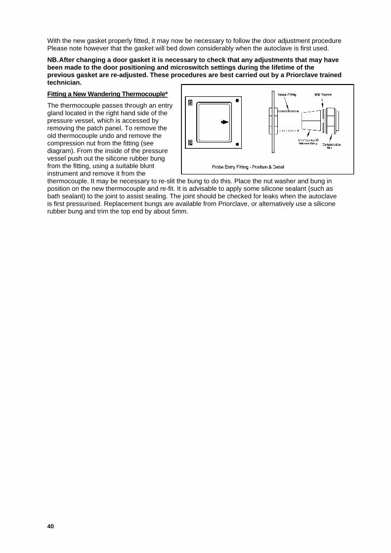
40
With the new gasket properly fitted, it may now be necessary to follow the door adjustment procedurePlease note however that the gasket will bed down considerably when the autoclave is first used.
NB.After changing a door gasket it is necessary to check that any adjustments that may havebeen made to the door positioning and microswitch settings during the lifetime of theprevious gasket are re-adjusted. These procedures are best carried out by a Priorclave trainedtechnician.
Fitting a New Wandering Thermocouple*
The thermocouple passes through an entrygland located in the right hand side of thepressure vessel, which is accessed byremoving the patch panel. To remove theold thermocouple undo and remove thecompression nut from the fitting (seediagram). From the inside of the pressurevessel push out the silicone rubber bungfrom the fitting, using a suitable bluntinstrument and remove it from thethermocouple. It may be necessary to re-slit the bung to do this. Place the nut washer and bung inposition on the new thermocouple and re-fit. It is advisable to apply some silicone sealant (such asbath sealant) to the joint to assist sealing. The joint should be checked for leaks when the autoclaveis first pressurised. Replacement bungs are available from Priorclave, or alternatively use a siliconerubber bung and trim the top end by about 5mm.

Priorclave Manual 2912832-EN.doc Issue Date:25 May 2006
41
Pipework Schematics
Standard Autoclave

42
Autoclaves with liquid ring vacuum pump
Autoclave Vessel
Autoclave Waterfill Tank(Optional)
Softened Water
Pump HeaderTank
Pump ProtectionFloat Switch Vacuum
Pump
Mains Water
SealedVentedDrain
Separate Drain(Overflows)
Tank Overflow
Autoclave Drain Valve (Optional)
Autoclave Main Vent Valve
Vacuum Activation Valve
Automatic WaterfillInlet Valves
Thermostat controlling water inletvalve for condenser
Air PurgeValve
Air IntakeFilter(Optional)
DrainCondenser(Optional)
Tank Overflow
FromAutoclaveDrip Tray
Autoclaves with Liquid Ring Vacuum PumpsKey:
Solenoid Valve Check Valve Strainer
15mm Tubing:
22/28mm Tubing:
Clear Plastic Small Bore Tubing:

Priorclave Manual 2912832-EN.doc Issue Date:25 May 2006
43
Spares List.
A full selection of spares are available from Priorclave Service or your local Priorclave dealer. Pleasegive your autoclave serial number when ordering parts.
A selection of the more commonly used parts is listed below:
Description Part Number
Air Intake Filter AFL/ACS/SML
Water Level Float Switch FLS/ACS/316
Gasket GAS/RSC/230
Heating Element 3.5 kW HTR/ACS/HOR
Setting Lock Keyswitch KEY/SLK/001
Thermal Lock Keyswitch KEY/TLK/002
Low Water Probe Electrode LWP/ACS/00C
Single Pole Circuit Breaker 6A MCB/ACS/006
3 Pole Circuit Breaker 32A MCB/ACS/032

44
Door Lock Microswitch MSA/CAN/VER
Door Roller Microswitch MSA/RSC/ROL
Door Microswitch MSA/RSC/SBT
Wandering Thermocouple Probe PRB/ACS/004
Pressure Gauge PSG/ACS/001
Pressure Switch PSS/SWI/001
Large Cable Port Bung SBG/ACS/022
Small Cable Port Bung SGB/ACS/015
Door Locking Solenoid SOL/QCS/001
Steam Generator Pressure stat Special Item
Safety Valve (½”) 4.5 Bar (SteamGenerator)
Special Order

Priorclave Manual 2912832-EN.doc Issue Date:25 May 2006
45
15mm (½”) Strainer STR/ACS/015
22mm( ¾”) Strainer STR/ACS/022
Output Card TAC/OPT/001
15mm (1/2 in BSP) Non Return Valve VNR/ACS/015
22mm (3/4 in BSP) Non Return Valve VNR/ACS/022
28mm (1 in BSP) Non-Return Valve VNR/ACS/028
Air Purge Valve (Complete) VPC/ACS/001
Air Purge Valve Element VPE/ACS/002
Safety Valve Complete VSC/ACS/022
15mm (1/2 in ) Solenoid Valve VVC/ACS/001
22mm (3/4 in BSP) Solenoid Valve VVC/ACS/022

46
Vent Valve 28mm (1in BSP) VVC/RSC/028
Printer Ribbon Cassette ZZZ/RIB/002
Printer Paper Roll ZZZ/ROL/005

Priorclave Manual 2912832-EN.doc Issue Date:25 May 2006
47
Notes

48

Priorclave Manual 2912832-EN.doc Issue Date:25 May 2006
49
Appendix A - Fault Finding & Rectification Guide
SY
Symptom Possible Cause Possible Solution- Power switched off at
isolator- Check
- Circuit Breaker Tripped - Reset and check cause
No Power
- Electrical Failure - Call Engineer
- Door is not closedcorrectly
- Open & Re-close. Checkouter cover is correctlyclosed.
Cycle does not commencewhen start button ispressed (Fault indicatorflashes) - Microswitch Failure - Check Microswitches
- Low Water Conductivityi.e. Distilled water
- Add Tap Water
- Probe dirty, damaged orremoved
- Visually check probe.Clean/Replace asnecessary
Low Water Indicator (F004)stays lit when correct waterlevel is achieved
- Wiring connections looseor damaged
- Check connections to probeand main control board.
- Temperature incorrectlyset
- Check setting & reset ifnecessary
- Circuit Breaker Trippedout
- Check Circuit Breakerposition. Check cause oftrip & reset if necessary.
- Heater(s) Failed - Check & Replace asnecessary. Check LowWater Probe.
- Heaters Overfurred - Check & Replace asnecessary.
Heating slow or notapparent
- Fault in control circuit. - Check all connections,output board function &thermal cut-out(s).
- Vent button in open position - Check Vent Indicator
- Freesteam time notcompleted (if option is fitted)
- Check Cycle ProgressIndicator Display
- Air purge valve failure - Check and replace internalparts or valve.
- Vent Valve stuck open - Check & Replace if necessary
- Safety Valve stuck open - Check for obstructions onlifting handle.
Autoclave does notpressurise
- Door incorrectly closed - Check door position andmicroswitch setting

50
Symptom Possible Cause Possible SolutionAir not fully purged. Due to :
- Incorrect Load Packing - Re-Load and re-start cyclewith (more) freesteaming.
- Faulty Air Purge Valve - Check & Replace if necessary
IncorrectTemperature/PressureCorrelation
- Faulty Controller or Gauge - Check function and calibration
- Temperature set too high - Check Temperature Setting
- Contactor Failure - Check & Replace if necessary.
- Safety Valve Faulty - Check the lock on the valve isintact and has not beentampered with and that thelifting handle is not obstructed.Check the pressure shown onthe gauge is above 2.2 Bar. Ifnot replace the valve.
Safety Valve opening
- Output board Failure - Check & Replace if necessary.
Door will not open onceAutoclave has cooled to80oC
- Thermal Lock Temperaturenot yet reached in LoadSimulator
- WAIT. Thermal Lock is set toLoad and not Chambertemperature.
- Safety delay not completed - Wait while ‘hoLd’ is displayedin the temperature display
- Thermal Lock Temperaturenot yet reached in loadsimulator
- Check Cycle Completeindicator is lit on cycleprogress display.
- Faulty Door system - Check Door Fault IndicatorLamp and Door Functions.
Door does not open whendoor button is pressed
- Thermal Lock previouslyoverridden
- Use thermal lock key to opendoor. Normal function willreturn after a complete cyclehas been run.
Fault Indication will not goout
- Fault not Re-set. (Refer to listof Fault Codes)
- Fault not Re-set. (Refer to listof Fault Codes)
If in any doubt about any of the above procedures do not hesitate to call Priorclave Serviceon:
+44 (0)20 8316 6620
or your nearest Priorclave approved service agent

Priorclave Manual 2912832-EN.doc Issue Date:25 May 2006
51

52
Appendix B - Steam Table
Autoclaves
Temperature (oC) Pressure (Bar)
100 0.00
105 0.20
110 0.43
115 0.69
120 0.99
121 1.06
122 1.13
124 1.25
126 1.35
128 1.55
130 1.70
132 1.86
134 2.04
136 2.21
138 2.40
140 2.60
Steam Generators (where fitted)
Temperature (oC) Pressure (Bar)
140 2.6
142 2.8
144 3.0
146 3.2
147.5 3.4
150 3.6
152 3.8
153.5 4.0
155 4.4
Correct Correlation between Temperature and Pressure shows correct operation of the autoclave andthat air purging is satisfactory.
NB.
This table is accurate at sea level and at moderate altitudes will be sufficiently accurate for itsintended purpose. However, at higher altitudes the pressures indicated will be slightly higher thanthose shown above.

Priorclave Manual 2912832-EN.doc Issue Date:25 May 2006
53

54

Priorclave Manual 2912832-EN.doc Issue Date:25 May 2006
55
Appendix C - Wiring Diagrams
Output Board Designations
Output Board 1
IN OUT FUNCTION1234
Output Board 2
IN OUT FUNCTION1234

56

Priorclave Manual 2912832-EN.doc Issue Date:25 May 2006
57
4P IS
OLA
TOR
SW
ITC
HE
DM
OD
EP
SU
MED
ICAL
MA
INS
FILT
ER
TAC
TRO
LC
ON
TRO
LB
OA
RD
TO W
ATE
R L
EV
EL
PR
OB
E
DO
OR
S
WIT
CH
PR
ES
SE
D
RE
LAY
FRL1
-1
PR
OG
RA
MM
ER
PR
INTE
R/P
AN
EL
DIS
PLA
YP
AN
EL
FRO
NT
SE
TTIN
G L
OC
KTH
ER
MA
LO
VE
R-R
IDE
PR
ES
SU
RE
SW
ITC
H
PR
ES
SU
RE
TRA
NS
DU
CE
R
MC
OO
LIN
GFA
N
DIS
PLA
Y
1ph-
MC
B6
AM
PTY
PE
B
DO
OR
S C
LOS
ED
FRO
M F
RO
NT
PLC
FRL
2/1
OP
TIO
NS
OU
TPU
TB
OAR
D 1
MA
INO
UTP
UT
BO
AR
D
40 42 41 44
22 25 24 26 59
0A 1A 39 38 37 36 49 48 75 74
27 108
0A 1A 105
104
101
100
57
58
40 47 8 917 18
0A 1A4 0
1111
1112
1413
1516
4344
4
2140
5857
101
100
1 2 3 NS
UP
PLY
E
0A1A 2140
321 4 0
106
TO H
EA
TER
C
ON
TAC
TOR
CO
ILP
AG
E 2
107
102
103
105
104
TO VA
CU
UM
CO
NTR
OL
PA
GE
2
TO VA
CU
UM
BR
EA
K S
OLE
NO
IDP
AG
E 2
39 38
4849
TO C
OO
LIN
G
FAN
PA
GE
2
TO V
EN
T S
OLE
NO
IDP
AG
E 2
37 36
VE
SS
EL E
AR
TH
0A
102
103
TO D
RA
IN
SO
LEN
OID
PA
GE
25253
TO WA
TER
FILL
S
OLE
NO
IDPA
GE
2
53 52
54A
54
VE
SS
EL
S/S
W
ATE
R L
EV
EL
FLO
AT
SW
ITC
H
40 23
RR
L1-1
DO
OR
S
WIT
CH
PR
ES
SE
D
RE
LAY
23
9A8AD
OO
RS
CLO
SED
FRO
M R
EA
R P
LCR
RL
2/1
THE
RM
AL
OV
ER
-RID
E
DIS
PLA
YP
AN
EL
RE
AR
PR
OG
RA
MM
ER
PR
INTE
R/P
AN
EL
1615
444
43
PA
NE
L P
RIN
TER

58
1 2 3 0
1 2 3
0H
YD
RA
ULI
CP
UM
PM
213A
3c-n
oC
ON
2/1
(See
PLC
Circ
uit D
iagr
am)
213
213A
3ph-
MC
B10
AM
PTY
PE C
213
66A
65A
64A
6665
64 VA
CU
UM
PU
MP
3ph-
MC
B10
AM
PTY
PE C
5A6A
7AV
AC
PU
MP
CO
N 4
HEA
TER
CO
N 1
HE
ATER
CO
N 3
HEA
TER
MAT
SC
ON
5
210
209
208
VES
SEL
HEA
TER
SH
EAT
ER M
ATS
204
1A RL5
/1


Priorclave Manual 2912832-EN.doc Issue Date:25 May 2006
61
Appendix D – Specification Tables
Model: PS/RSV/EH230 PS/RSV/EH350Dimensions
Chamber dimensions(wxdxh)
580x650x675mm 580x950x675mm
Working dimensions(wxdxh)
580x600x600mm 580x900x600mm
Capacity 209 Litres 313LOutside dimensions(wxdxh)
830x1100x1880mm 830x1400x1880mm
Minimum InstallationArea Required (wxd)
830x1300mm 830x1600mm
Recommended spacerequired for serviceaccess.
1M to each sideWhere autoclave cannot be pulled forward for service access to sides
WeightUnloaded 850kG 950kGWith water charge 880kG 980kGDoor 60kG 60kGPressure Vessel 250kG 350kG
ElectricalPower Supply Required 400V 50/60Hz 3 Phase with Neutral and Earth. 21kW, 30A/phase.
SteamSteam Supply Required Not Required
Water SupplyAutomatic WaterfillSystem (if fitted)
Soft or softened water. 15mm BSP. 20psi
Optional Condenser 28mm BSP 60psiAir Supply
Air Supply required Models with Air Ballasting from an external supply (PC/ABC/000):100psi Dry Oil-Free
DrainageMain Drain Connection 28mm BSPSecondary DrainConnections
15mm BSP
Max. Sound LevelWithout Vacuum Pump Approx. 30db @ 1MWith Vacuum Pump Approx. 75db @ 1M
Max. Heat Emission - Full CycleAverage (Standard cycle) 10.5kW per cycleFor other cycles ((21hx10.5p)x0.75)/t) kW/Hour
Where: h = heat-up time (hrs), p = process time (hrs), t = Total cycle*(hrs)
* to thermal lock temperature

62

Priorclave Manual 2912832-EN.doc Issue Date:25 May 2006
63
Appendix E – Other Items Fitted

64

Priorclave Manual 2912832-EN.doc Issue Date:25 May 2006
65
STERLINGExtracts from Sterling Fluid Systems (UK) Ltd Manual.
LEM. 26 251,LEL. 91 -251
Single–stage liquid ring vacuum pumps in
compact design
Operating instructions
To be strictly observed
Contents1.0 Safety 552.0 Application 573.0 Putting into operation and out of operation 584.0 Maintenance, disassembly, assembly 595.0 Help in case of trouble 646.0 Technical data 64
Annex 67Sectional drawings 67Dimension tables 67Operating data, make-up water flows 68
Please be aware of your responsibility for your fellow men when working at the pump or the pump unit!
Attention: This pump or this pump unit, respectively maybe mounted and put into operation by qualifiedtechnical personnel only and these operating Instructions and the effective regulations have strictly to beobserved. If you do not pay attention to these operating Instructions,
- danger may be created for you or your colleagues,- the pump or the pump unit may be damaged,- the manufacturer is not liable for damages resulting from this non-observance!
Document No.......: BA 26397-EN-OO
File .......................: VFLEM2de-.doc
Date : 28.08.2001
Sterling Fluid (UK) Systems Limited
Atlantic Street, Altrincham,
Cheshire,
WA14 5DH, England.

66
1.0 Safety
This operating manual gives basic instructions which are to be observed during installation, operation andmaintenance of the pump. It is therefore imperative that this manual is read by the responsible person-nel/operator prior to assembly and commissioning. It is always to be kept available at the installation site.
It is not only the general safety instructions contained under this chapter Safety to be observed, but alsothe specific information provided under the other chapters.
1.1 Identification of safety prescriptions in the operation instructions
Safety prescriptions given in these operation instructions, non compliance with which would affect safetyare identified by the following symbol:
Danger symbol as per DIN 4844-W9(ISO 3864 -B.3.1 )
or in case of warning of electrical voltage with:
Danger symbol as per DIN 4844 W-8(ISO 3864 -B.3.6)
The word
identifies the safety regulations whose non compliance may cause danger for the machine and itsfunction. It is imperative that signs affixed to the machine, e.g.
- arrow indicating the direction of rotation- symbols indicating fluid connections- type plate
must be observed and kept legible.
1.2 Qualification and training of personnel
The personnel responsible for operation, maintenance, inspection and assembly must be adequatelyqualified. Scope of responsibility and supervision of the personnel must be exactly defined by the plantoperator. If the staff does not have the necessary knowledge, they must be trained and instructed whichmay be performed by the machine manufacturer or supplier on behalf of the plant operator. Moreover, theplant operator is to make sure that the contents of the operation instructions are fully understood.
1.3 Hazards in case of non compliance with the safety instructions
Non compliance with the safety instructions may produce a risk to the personnel as well as to the environ-ment and the machine and results in a loss of any right to claim damages.
For example non-compliance may involve the following hazards:
- failure of important functions of the machine/plant- failure of specified procedures of maintenance and repair- exposure of people to electrical, mechanical and chemical hazards- endangering the environment owing to hazardous substances being released
!
ATTENTION

Priorclave Manual 2912832-EN.doc Issue Date:25 May 2006
67
ec
1.4 Compliance with regulations pertaining to safety at work
When operating the pump the safety instructions contained in this manual, the relevant national accidentprevention regulations and any other service and safety instructions issued by the plant operator are to beobserved.
1.5 Safety instructions relevant for operation
If hot or cold machine components involve hazards, they must be guarded by the user against accidentalcontact.
Guards for moving parts (eg. couplings) must not be removed from the machine while in operation.
Any leakage of hazardous (e.g. explosive, toxic, hot) fluids (e.g. from the shaft seal) must be drainedaway so as to prevent any risk occurring to persons or the environment. Statutory regulations are to becomplied with.
Hazards resulting from electricity are to be precluded by the user (see for example the VDE specificationsand the bye-laws of the local power supply utilities).
1.6 Safety instructions relevant for maintenance, inspection and assembly work
It shall be the plant operator's responsibility to ensure that all maintenance, inspection and assemblywork is performed by authorised personnel who have adequately familiarised themselves with the subjectmatter by studying this manual in detail.
Any work on the machine shall only be performed when it is at a standstill. It is imperative that the pro-cedure for shutting down the machine described in this manual is to be followed.
Pumps and pump units which convey hazardous media must be decontaminated.
On completion of work all safety and protective facilities must be re-installed and made operative again.Prior to re-starting the machine, the instructions listed under "first commissioning" are to be observed.
1.7 Safety instructions for the use in areas with explosion hazard
In this paragraph information are given for an operation in areas with explosion hazard.
1.7.1 Arrangement of the units
If the pump is completed with other mechanical or electrical components to one unit, thecomplete unit may be considered only as device category according to the directive 94/9/ECwhich is fulfilled by all used components.
Note:
This instruction gets special meaning when using pumps which are corresponding to a devicecategory according to the directive 94/9/EC, however, are driven by a motor which does not meetthese criteria. Then it might be that the pump has been provided with the EX-sign but the unitmust not be used in areas with explosion hazard due to the non EX-admitted motor. So theoperator has always to pay attention to the conformity with the directive 94/9/EC of all usedcomponents of the pump unit.
1.7.2 Execution of coupling guards for shaft couplings
Coupling guards which shall be used in areas with explosion hazard have to fulfil the followingcriteria:
non sparking material e.g. brass has to be used or
steel plate constructions have to be used, which are executed in a way that with faults to be fore-seen (e.g. deformation by stepping on the coupling guard) a mechanical contact of the rotatingparts is impossible.
1.7.3 Surveillance of technical parameters
When using pumps in areas with explosion hazard the operator has to check regularly thefollowing parameters:
- leakage of the shaft seals- if necessary bearing temperatures- liquid level in the pump during commissioning- for pumps with magnetic coupling the temperature of the electrically conductive isolation

68
!
shroud has to be controlled
The operator has to ensure that the pump, with abnormal conditions, will be taken out ofoperation / not be taken again in operation at short notice. The advice regarding operationand maintenance given in this operation manual have to be kept to.
Particular information concerning the surface temperatures of the pump are given later inthis operation manual.
1.7.4 Avoidance of sparks caused by exterior impact effect
The operator has to ensure that with an operation of the machine in areas with explosionhazard no exterior impact effect to the machine casing may create sparks.
1.8 Unauthorised alterations and production of spare parts
Any unauthorised modification of the machine will result in an exemption of Sterling SIHI from any liability.In such cases the operator of the machine takes over the responsibility for the safe operation.
Using spare parts and accessories authorised by the manufacturer is in the interest of safety. Use ofother parts may exempt the manufacturer from any liability.
1.9 Unauthorised mode of operation
The reliability of the machine delivered will only be guaranteed if it is used in the manner intended and inaccordance with the instructions of this manual. The specified limit values must not be exceeded underany circumstances.
1.10 Warranty I guarantee
Sterling SIHI guarantee for a longterm, satisfactory operation if
- the pump is installed and operated in compliance with these instructions and under conditionsapproved by Sterling SIHI.
- modifications only will be carried out with Sterling SIHI's agreement.
2.0 Application
Liquid ring vacuum pumps and compressors are used to deliver and compress gases and vapours. It isalso possible to handle little flows of liquid.
The pump is to be applied only for the operating conditions stated by the orderer and confirmed by thesupplier. Guarantee is assumed within the scope of our conditions of sale and delivery.
2.1 Warning of misuse
2.2 Construction and mode of operation
The pump operates according to the liquid ring principle. The vane wheel impeller is arrangedeccentrically in the circular pump casing. It transfers the drive power to a liquid ring that formsconcentrically to the casing when starting up the pump. This arrangement causes the liquid to leave andto enter piston-like the vane wheel impeller cells. In the area of the leaving liquid ring the vane wheelimpeller cells get filled with the gas to be handled via a suction opening. In the area where the liquid ringenters the vane wheel impeller cells the gas will be compressed and pushed out via a discharge opening.
During operation the pump must continuously be supplied with service liquid, normally water. This liquidserves to eliminate the heat resulting from the gas compression, which is taken up to a great extent bythe liquid ring and to replenish the liquid ring, because part of the liquid is leaving the pump together withthe gas. The reuse of the liquid as service liquid is possible.extent by the liquid ring and to replenish theliquid ring, because part of the liquid is leaving the pump together with the gas. The reuse of the liquid asservice liquid is possible.
2.3 Technical limits of operation
You may use the pump only for the approved operating conditions as otherwisehazards for people and environment may occur.

Priorclave Manual 2912832-EN.doc Issue Date:25 May 2006
69
Pay attention to the following operation limits.
The limit values are shown later in the manual:
- Max. temperature of the medium handled- Max. temperature, max. viscosity and max. density of service liquid- Max. permissible discharge pressure and max.permissible pressure difference- Max. speed
Avoid the following conditions when using the liquid ring vacuum pump:
- The combination of several limiting values- Frequent switching operations (max. 5 - 10 per hour- Pressure jumps of the gas- Temperature jumps of the gas or of the service liquid
3.0 Putting into operation and out of operation
The work described in this chapter must be carried out by trained skilled staff only.
3.1 Safety measures
- Electrical connections are to be carried out according to the regulations of the local public utilities andto the ELexV standards. Furthermore the ex-rules of the BG chemistry are to be observed.
- Only correspondingly authorised personnel may carry out the work at the electrical installation.
- Fill the pump properly.- Check the sense of rotation only when the pump is filled.- In case of handling explosive, toxic, hot or aggressive media it must be ensured that persons and
environment are not endangered.- When handling easily inflammable gases consider the possible generation of explosive gas/air mixtu-
res; if necessary, the pump is to be flushed with inert gas.- The pump may be operated only if a continuous supply of service liquid is secured.
3.2 Filling and emptying
Before the first start-up the pump must be filled with service liquid.
The filling with service liquid is made via the make-up liquid connection (shut-off valve). When starting-upthe pump the liquid level in the pump must not exceed shaft height .
The pump can be emptied through the drain connection Mind that there may be dead spaces within thepump, in which sediment of service liquid can remain. Because of this flush the pump beforedisassembly, especially when using toxic media.
ATTENTION
ATTENTION
!

70
3.3 Electrical connection
The motor has to be connected according to the circuit diagram in the terminal box.
3.4 Connection and verification of accessories and control devices
The connection and the verification of the control devices and of the accessories have to be made inaccordance with the attached operating instructions of the different apparatus.
3.5 Verification before switching-on
- The pump never must run dry.- Fill the pump with service liquid before the first start-up.- The liquid level shall not exceed the shaft height.- Never start-up the pump when the discharge side is closed.
3.6 Control of sense of rotation
The sense of rotation has to be checked by short-time switching on the motor the arrow at the pumpcasing indicates the sense of rotation)
3.7 Putting into operation
For putting into operation proceed as follows:
1. Switch on the motor.
2. Open the shut-off valve for the service liquid.
3.8 Putting out of operation
For putting out of operation proceed as follows:
1. Close the shut-off valve for the service liquid.
2. Ventilate the suction chamber.
3. Switch off the motor.
If there is the risk of freezing, drain the pump, the liquid separator and the pipelines. The pump has to bepreserved should it be stopped for a longer period of time.
4.0 Maintenance, disassembly, assembly
The work described in this chapter must be carried out by trained skilled staff only.
Work on electrical connections must be carried out by authorised skilled staff only.
4.1 Preconditions
The pump respectively the pump unit has been put out of operation according to the instructions ofchapter 3.
ATTENTION
ATTENTION

Priorclave Manual 2912832-EN.doc Issue Date:25 May 2006
71
4.2 Safety measures
- When mounting and dismounting the pump observe especially that no toxic or aggressive media canescape from open lines. Secure the shut-off devices against unauthorised operating.
- Drain the pump before disassembly out of the plant. After the draining liquid residuals remain in thepump which must be removed by flushing the pump with a suitable liquid.
- The electrical connections must be connected and disconnected only after removal of correspondingfuses.
LEM: For motors of the protection type EEx e ll T3 the following instructions are to be observed:
In case of repair, e.g. disassembly of the mechanical seal, it is admissible that the service personnel ofSterling SIHI or of the customer dismounts the pump casing (here corresponding with the motor flange)from the motor.
However, it is a basic requirement that no modifications are carried out at the motor electric (winding,terminal box).
4.3 Maintenance
The pump requires only little maintenance. However following points must be observed:
- LEM:
The antifriction bearings of the motor have permanent lubrication. The grease portion filled in by themotor supplier, according to experience, will be sufficient for several years.
- The mechanical seal do not require any maintenance. With normal operation leakages can occuronly after several 1.000 operation hours, if the wear parts are worn out.
- In case of danger of freezing the pump, liquid separator and pipelines are to be drained. The pumpmust be preserved.
- In case strongly calcareous water is used as service liquid, the pump must be opened at least atintervals of a half-year and the calcareous deposit must be removed.
- The calcareous deposits can be avoided, if the service liquid is prepared by a suitable agent. Themeasures to be taken depend on operation time and water quality.
- In case the pump has not been into operation for a longer period of time, it must be drained andpreserved, if necessary.
- As contamination accumulates in the pump and in the liquid separator, those are to be cleaned atcorresponding intervals.
!
ec

72
4.4 Notes
4.4.1 Assembly tools
For the disassembly and assembly of the pump we recommend the following special tools: Extractorfor the vane wheel impeller (easy to make or available as accessory) and socket wrench for tie bolts(LEM. 26/51).
4.4.2 Sealing surfaces and centrings
All parts of the pump, especially the sealing surfaces and centrings are to be treated carefully.
4.4.3 Spare parts
When ordering spare parts indicate the item No. of the part, pump type and pump No. (see annex or typeplate). Typical spare parts are marked with a frame in the sectional drawing.
After dismantling the vane wheel impeller 23.50 always install a new tolerance sleeve 53.10 before re-assembly.
4.4.4 Motor specification
The electrical data of the motor can be taken from the motor type plate.
LEM: When ordering spare parts indicate pump type and pump No. (see annex).
4.4.5 Sectional drawings
The disassembly and assembly can be carried out acc. to the written description and to the sectionaldrawing (see annex).
4.5 Disassembly
Pay attention, especially when using dangerous media, that also after careful flushing of the pumpresiduals of the medium or of the service liquid can remain in dead spaces of the pump.
4.5.1 Preparation of the disassembly
Proceed according to the following checklist:
1. Switch the power supply of the motor free from tension.2. Disconnect the motor.3. Drain the installation at least within the pump area, i.e. between the gates at suction and discharge
side.4. If necessary, disconnect existing measuring probes or control instruments respectively and dismount
them.5. Drain the pump.6. Dismount the pump unit out of the plant.7. If necessary, flush the pump.
4.5.2 Disassembly of the pump
Proceed as follows:
LEM:
1. Remove the cover 16.10.
2. With extractor, as shown, withdraw the vane wheel impellerfrom the shaft.
Subsequently take the tolerance sleeve 53.10 out of the bore of
ATTENTION
!

Priorclave Manual 2912832-EN.doc Issue Date:25 May 2006
73
the vane wheel impeller 23.50.
3. Separate the guide disk 13.70 from the vacuum casing 10.10.
If necessary, remove the valve plate 75.11 and the protection plate 58.01.
Remove the rotating part of the mechanical seal 43.30 by rotary motion from the shaft end of themotor (LEM. 91-251).
A C D z
LE.26/51 M8 x 15 M8 x 30 M16 x 90 39
LE. 91/126 M10 x 20 M8 x 35 M16 x 90 45
LE. 161 M12 x 25 M8x45 M16x90 66
LE. 251 M12 x 25 M8x35 M16x90 80
(8 = fiat-bar steel)
4. Separate the vacuum casing from the motor 80.00 (LEM. 26/51: for that purpose remove the ventilatorcover of the motor and loosen the motor clamping screws}. The rotating part of the mechanical seal43.30 can be drawn from the motor shaft end together with the casing (LEM. 26/51}. Remove thestationary ring of the mechanical seal 43.30, if worn out also the O-ring 41.20 and the radial sealingring 42.10 out of the casing 10.10.
4.6 Assembly
4.6.1 Preparation for Assembly
1. Clean carefully all pump parts Pay attention that the sealing surfaces have no grooves and that theguide disk is plane. If necessary, the guide disk must be smoothed on a levelling plate by means ofabrasive cloth.
2. Coat the running surface of the guide disk as well as all threads and fittings (except the sealingfittings} with Molykote slide paste.
3. Provide the sealing surfaces with sealing compound shortly before jointing (last sign of the pumpcode
“0” liquid“4” Teflon“7” Teflon / O-ring
In general the liquid sealing compound Epple 33 is used for grey cast iron parts and Silastik forstainless steel parts.
4. During assembly no foreign substances and no superfluous sealing compound must enter the pump.
5. Use jaws when clamping parts for assembly.
4.6.2 Tightening torques
When tightening the screws and nuts the following tightening torques must be observed:
thread M5 M6 M8 M 10 M 12
tightening
torque6,5 Nm 8,5 Nm 12 Nm 25 Nm 40 Nm
4.6.3 Assembly of the pump
Proceed as follows:
(Pay attention to the sectional drawings!}
LEM. 26 251:
1. Insert radial seal ring 42.10 into the vacuum casing 10.10. Press the stationary ring of themechanical seal 43.30 into the bore of the casing.
2. Fasten the casing 10.10 to the motor 80.00.
3. Slip the rotating parts of the mechanical seal 43.30 on the motor shaft end 80.00.

74
4. Put the O-ring 41.20 into the groove. Connect the valve plate 75.11 and the protection plate 58.01with the guide disk 13.70 (secure the screws, e.g. with Loctite 222} or put the valve balls 75.40 intothe bores of the casing 10.10.
5. Coat the sealing faces of the casing 10.10 with sealing liquidcompound. Fasten the guide disk 13.70 to the vacuum casing10.10. If necessary put on a spacer to the motor shaft end..
6. For fastening of the vane wheel impeller 23.50 and adjustment offront gap firstly it is necessary to tighten the guide disk 13.70 to thecasing.
7. Now slip the vane wheel impeller 23.50, with the tolerance sleeve53.10 inserted, on the motor shaft end 80.00. Press the vanewheel impeller 23.50 on the shaft end until the required distance ofthe gap between vane wheel impeller 23.50 and guide will beachieved (see sketch).
E F G
LE. 26/ 51 M8 x 30 M8 x 100 M8
LE. 91/126 M8 x 35 M10 x 105 M 10
LE. 161 M8 x 45 M12 x 140 M12
LE. 251 M8 x 25 M12 x 140 M 12
(B = fiat-bar steel, H = disk, min. outer-0 20)
8. Loosen the guide disk 13.70. Insert a Teflon sealing string (01 mm) in the V-groove of the cover16.10. Fasten the cover 16.10 on the guide disk 13.70.
9. Tighten steadily the hexagonal screws 90.10 crosswise.
4.7 Test Work
Do not turn the pump unnecessary without liquid.
After assembly the following test work must be carried out:
1. Check the easy running of pump by rotating the motor fan.
In case the pump should be jammed tight, probably the vane wheel impeller is incorrectly adjusted.The fault must be eliminated.
2. Carry out a hydrostatic pressure test with 3 bar (hydraulic test).
Drain the pump.
3. Carry out a leakage test (with foaming media).
Front Gap: 0,10 – 0,12 mm
ATTENTION

Priorclave Manual 2912832-EN.doc Issue Date:25 May 2006
75
5.0 Help in case of trouble
Trouble elimination must be carried out by trained skilled staff only.
5.1 Preconditions
Precondition for a proper operation of the pump is the observance of the instructions for installation andstarting-up of the pump given previously.
The different modes of operation of the pump are described earlier.
5.2 Trouble, causes and elimination
Trouble Cause Elimination
Suction volume flow of thepump not sufficient Suction line is leaky.
Check the flange connections andretighten them.
If necessary the seal has to bereplaced.
Decrease of the suction volumeflow by increased service liquidtemperature (Values indicated inthe catalogue are related to waterof 15 °C)
Regulate the temperature of theservice liquid by increasing the make-up liquid flow or by increasing thecooling liquid flow in the heatexchanger.
Forming of deposits in the pump
Check the pump for contaminationand deposits.
Clean the pump.
If necessary, take precautions.
Pump causes creakingnoise(cavitation)
The pump runs at considerablylower suction pressures thanindicated in the catalogue.
Connect the protection againstcavitation
The service liquid temperature ishigher than determined in theannex.
Regulate the temperature of theservice liquid by increasing themake-up liquid flow or by increasingthe cooling liquid flow in the heatexchanger.
Escape of liquid betweenmotor and pump Mechanical seal is leaky
Change the mechanicalseal(assembly and disassemblyaccording to chapter 4).
Liquid at the gas outlet Make-up liquid flow F too Qreat Throttle the make-up liquid flow.
Drain liquid flow A too small,overflow clogged
Check the overflow for sufficientpassage, eliminate the clogging.
6.0 Technical data
6.1 Catalogue data of the pump
In the annex are indicated the operating data of the liquid ring vacuum pump according to the conditionsstated in the catalogue (gas handled: air at 20 °C, service liquid: water at 15 °C).
6.2 Make-up liquid flow
In the annex are stated the make-up liquid flows F for combined operation (KB) and for the make-upliquid operation (FB) when using water as service liquid.
The make-up liquid flows indicated in the column differences in temperature are applicable to thecompression of dry gases. If condensing vapours are compressed, the make-up liquid flows shall beincreased because of the condensation heat to be dissipated additionally.

76
6.3 Limiting operating data
Pump type unit LEM 26 / 51 LEM 91/1261 LEM 161 LEM 251
LEL91/126 LEL 161 LEL 251
min. suction pressure mbar 33
admissible dischargeoverpressure bar 0,3 LEM 0,3 / LEL 0,5
adm. pressure differencebetween max. mbar 1100 LEM 1100 / LEL 1500
suction and discharge side min. 200 200
max. gas inlet dry °C 200
temperature vapour saturated °C 100
max. speed rpm 3600 1750
service liquid max. °C 80
temperature min. °C 10
max. service liquid density kg/m3 1200
max. service liquid viscosity mm2/s 4
Absolute pressures [mbar]
Overpressures [bar]
Table 6.3: Limiting operating data
The surface temperatures at the external pump components result from the temperatures of the pumpingmedium or of the service liquid. Dependent on the existing operating conditions the increase intemperature of the service liquid may be about 5 -20 K when passing through the pump.
6.4 Admissible branch load
Forces Fx, Fy, Fz[N]
Moments Mx, My, Mz[Nm]
LEM. 26/51: 50 15
LEM / LEL 91/126 A.: 50, 50, 80 15, 15,50
LEM / LEL 91/126 C.: 100,100, 160 30,30, 100
LEM / LEL 161: 100, 100, 160 30,30,100
LEM / LEL 251 : 160, 160, 220 50,50, 140
ATTENTION

Priorclave Manual 2912832-EN.doc Issue Date:25 May 2006
77
6.5 Type codes
The following table explains the Sterling SIHI-type code (extract from the standard delivery programme).
series +size
hydraulics +bearings shaft sealing motor
designationmaterial design casingseal
A. hydraulics A AAE standardmechanical seal
C.hydraulics Awith flangeconnection
AA1 O-ringsPerbunan OA main parts of GG 0 liquid
sealing
.Z
two greaselubricatedantifrictionbearings
arranged in themotor
B3N
as ME, but O-rings Viton
mechanical sealO-ringsPerbunan
4B main parts of CrNi Mo cast steel 7O-rings,
Teflon cord
BLU
.B
as .Z, butarranged inthe motorcarrier
mechanical sealO-rings Viton
LEM 26 AZ AAE, AA1 OA,4B 7 AW,BW
LEM 51
91
-HW,JW
LEM 126 AZ, CZ
-FW,GW
161 AAE, M1, B3N OA,4B 0, 7
91
----'ES,FS
LEL 126
-AB,CB FS
161 FS,GS
LEM 251 CZ B3N,BLU OA,4B 7 AW,BW
LEL 251 GB GS

78
Annex
-Sectional drawings
-Dimension tables

Priorclave Manual 2912832-EN.doc Issue Date:25 May 2006
79
-Operating data, make-up water flows