operating unit 128x64 with touch panel · operating unit 128x64 with touch panel issue 01-2018...
TRANSCRIPT

OPERATING UNIT128x64 with touch panel
Issue 06.2020
Zeppelinstr. 19 · D-82205 Gilching · Phone +49-(0)8105-778090 · Fax +49-(0)8105-778099 · www.lcd-module.de · [email protected]
Dimension: 71.4x54.4x13.6mm
EA eDIP128B-6LWTP
EA eDIP128W-6LWTP
TECHNICAL DATA* LCD-GRAPHIC DISPLAY WITH A RANGE OF GRAPHIC FUNCTIONS* 3 DIFFERENT INTERFACES ONBOARD: RS-232, I²C-BUS OR SPI-BUS* 128x64 OR64X128 DOTS WITH LED BACKLIGHT* WHITE LED-BACKLIGHT BLUE NEGATIVE OR* BLACK&WHITE POSITIVE, FSTN-TECHNOLOGY* 8 BUILT-IN FONTS* FONT ZOOM FROM 2MM TO ABOUT 80MM, TURNABLE IN 90° STEPS* POWER SUPPLY WIDE RANGE +3,3V / 190mA/12mA ... +5V / 125mA / 20mA (WITH/
WITHOUT BACKLIGHT)* POWER-DOWN-MODE 25 µA, WITH WAKEUP VIA TOUCH OR I²C* POSITIONING ACCURATE TO THE PIXEL WITH ALL FUNCTIONS* LINE, DOT, AREA, AND/OR/EXOR, BARGRAPH...* CLIPBOARD FUNCTIONEN, PULL-DOWN MENÜ* UP TO 256 PICTURES INTERNALY STORED* UP TO 256 MACROS PROGRAMMABLE (64kB EEPROM ONBOARD)* MIX TEXT AND GRAPHIC, FLASHING ATTRIBUTE: ON/OFF/ INVERT* BACKLIGHT BRIGHTNESS PER SOFTWARE* ANALOGUE TOUCH PANEL: VARIABLE GRID* FREE DEFINABLE KEY AND SWITCH
ORDERING CODESDISPLAYS128x64 DOTS, WHITE LED-BACKLIGHT, BLUENEGATIVE EA eDIP128B-6LWAS ABOVE, BUT WITH TOUCH PANEL EA eDIP128B-6LWTP128x64 DOTS, WHITE LED-BACKLIGHT, POSITIVE MODE, FSTN EA eDIP128W-6LWAS ABOVE, BUT WITH TOUCH PANEL EA eDIP128W-6LWTPSTARTERKITINCLUDES EA eDIP128B-6LWP AND EVALUATION BOARD WITH USBFOR DIRECT CONNECTION TO PC AND INTERFACE BOARDS FORCONNECTION WITH YOUR HOST SYSTEM EA EVALeDIP128BAS ABOVE, BUT WITH EA eDIP128W-6LWTP EA EVALeDIP128WADDTIOTNAL PARTSMOUNTING BEZEL (ALUMINIUM), BLACK ANODIZED EA 0FP130-6SWSOCKET 1x16, 4.5mm HEIGHT (1 PIECE) EA B254-16

EA eDIP128-6Page 2
ELECTRONIC ASSEMBLY reservesthe right to change specificationswithout prior notice. Printing andtypographical errors reserved.
CONTENTS
GENERAL ..................................................................................................................... 3
RS-232.......................................................................................................................... 4
RS-485, USB ................................................................................................................ 5
SPI ................................................................................................................................6
I²C ................................................................................................................................7
IN- AND OUTPUTS.......................................................................................................8
ROTATED MOUNTING ..................................................................................................9
POWER-DOWN-MODE................................................................................................. 9
SOFTWARE PROTOCOL ......................................................................................... 10 - 11
TERMINAL MODE, FILL PATTERN .............................................................................. 12
COMMANDS/ FUNCTIONS IN TABULAR FORMAT ................................................. 13 - 17
TOUCHPANEL , KEY STYLE .................................................................................. 16 - 17
RESPONSES OF THE OPERATING PANEL................................................................. 18
CHARACTER SETS ................................................................................................. 19 - 20
FLASH- MODE ............................................................................................................ 21
MACRO PROGRAMMING........................................................................................ 24 - 25
ELECTRICAL CHARACTERISTICS.............................................................................. 26
MOUNTING BEZEL ..................................................................................................... 27
DIMENSION ................................................................................................................ 28
Documentation of revision
Date Type Old New Reason / Description
October, 2010 0.1 preliminary Version
August, 2011 1.0 first release

EA eDIP128-6Page 3
ELECTRONIC ASSEMBLY reservesthe right to change specificationswithout prior notice. Printing andtypographical errors reserved.
GENERALThe EA eDIP series of displays are the world’s first displays with integrated intelligence. In addition to a varietyof integrated fonts that can be used with pixel accuracy, they offer a whole range of sophisticated graphicsfunctions.The displays are ready for operation immediately with an operating voltage range of +3.3V..+5V. They arecontrolled via one of the 3 integrated interfaces: RS-232, SPI or I²C. The displays are “programmed” by meansof high-level language-type graphics commands. There is no longer any need for the time-consumingprogramming of character sets and graphics routines. The ease of use of this display with its touch paneldramatically reduces development times.
HARDWAREThe display is designed to work at an operating voltage range of +3.3V..+5V. Data transfer is either serial andasynchronous in RS-232 format or synchronous via the SPI or I²C specification. To improve data security,a simple protocol is used for all types of transfer.
ANALOGUE TOUCH PANELAll versions are also available with an integrated touch panel: You can make entries and menu or bargraph settings by touching the display. The labeling of the “keys” is flexible and can also be changed duringruntime (different languages, icons). The drawing of the individual “keys” and the labeling is handled by theintegrated software.
LED ILLUMINATION, B- AND W-TYPESAll displays in blue-and-white (B) and black-and-white (W) are equipped with a modern, low powerconsumption LED backlight. Whereas the black&white can still be read even when the backlight is switchedoff completely, the blue-white display requires a minimum level of illumination to be legible. The backlight canbe switched off with a software command and the brightness can be adjusted. We recommend the black&whiteversion for use in direct sunlight. For all other applications, we recommend the high-contrast, blue-whiteversion. Note that the white LED backlight is subject to aging. That means switching off or dimming backlightis a must for 24-hour-applications.
SOFTWAREThis display is programmed by means of commands, such as draw a rectangle from (0,0) to (64,15). Noadditional software or drivers are required. Strings and images can be placed with pixel accuracy. Text andgraphics can be combined at any time. Different character sets can be used at same time. Each character setand the images can be zoomed from 2 to 8 times and rotated in 90° steps. With the largest character set, thewords and numbers displayed will fill the screen.
ACCESSORIESEvaluation-Board (Programmer) for internal data flash memoryThe display is shipped fully programmed and with all fonts. The additional Evaluation-Board is thusgenerally not required.However, if the internal character sets have to be changed or extended, or if images or macros haveto be stored internally, the Evaluation-Board EA 9777-2USB, which is available as an accessory, willburn the data/images you have created into the on-board EEPROM (64 kB) permanently.The Evaluation-Board runs under Windows and is connected to the PC’s USB interface. It is shippedwith an interface cable and the installation software. The Evaluation-Board is equipped with serveralLEDs, pushbottons and potentiometer to test all peripherial modes of the eDIP.Interface-Expansion for Evaluation-Board (included in the Starter-Kit):Wtih the expansion EA 9777-2PE for the Evaluation-Board all interfaces of the display are madeavailable with the help from small adapter boards: RS-232, RS-485, SPI, I²C, RS-232 (CMOS level).Further information you will find in the datasheet of the Evalution-Board.

EA eDIP128-6Page 4
ELECTRONIC ASSEMBLY reservesthe right to change specificationswithout prior notice. Printing andtypographical errors reserved.
Baud RatesBaud0 Baud1 Baud2 data format
8,N,11 0 0 24000 1 0 48001 1 0 96000 0 1 192001 0 1 384000 1 1 576001 1 1 1152000 0 0 230400
Pinout eDIP128-6: RS-232/RS-485 modePin Symbol In/Out Function Pin Symbol In/Out Function
1 GND Ground Potential for logic (0V) 17 DPROT In L: Disable Smallprotokolldo not connect for normal operation
2 VDD Power supply for logic (+3,3V..5V) 18 PWR OutL: Normal OperationH: Powerdownmode
3 NC do not connect 19 NC do not connect
4 NC do not connect 20 TESTSBUF
InOut
open-drain with internal pullup 20k..50kIN (Power-On) L: TestmodeOUT L: data in sendbuffer
5 RESET In L: Reset 21 GND Ground (0V)6 BAUD0 In Baud Rate 0 22 VDD Power supply (+3,3..5V)7 BAUD1 In Baud Rate 1 23 NC do not connect8 BAUD2 In Baud Rate 2 24 NC do not connect9 ADR0 In Address 0 for RS-485 25 IN8/OUT1
8 digital inputs(internal 20k..50k pullup)
alternativ up to 8 digital outputsmaximum current:IOL = IOH = 10mA
10 RxD In Receive Data 26 IN7/OUT211 TxD Out Transmit Data 27 IN6/OUT312 EN485 Out Transmit Enable for RS-485 driver 28 IN5/OUT4
13 WUP InL: (Power-On) disable Power-On-MacroL: Wakeup from Powerdownmode 29 IN4/OUT5
14 ADR1 In Address 1 for RS-485 30 IN3/OUT615 ADR2 In Address 2 for RS-485 31 IN2/OUT716 BUZZ Out Buzzer output 32 IN1/OUT8
Application note
RS-232 INTERFACEIf the display is wired as shownbelow, the RS-232 interface isselected. The pin assignment isspecified in the table on the right.The RxD and TxD lines leadCMOS level (VDD) to amicrocontroller, for example, fordirect connection.If “genuine” RS-232 levels arerequired (e.g. for connection to aPC), an external level converter(e.g. MAX232) is required.
BAUD RATESThe baud rate is set by means of pins 6, 7 and 8 (baud 0 to 2). The dataformat is set permanently to 8 data bits, 1 stop bit, no parity.
RTS/CTS handshake lines are not required. The required control istaken over by the integrated software protocol (see pages 10 and 11).
Note:The pins BAUD 0 to 2, ADR 0 to 2, DPOM,DPROT and TEST/SBUF have an internalpullup, which is why only the LO level(0=GND) is to be actively applied. Thesepins must be left open for a hi level.For RS232 operation (withoutaddressing) the pins ADR 0 to ADR 2must be left open.On pin 20 (SBUF) the display indicateswith a low level that data is ready to beretrieved from the internal send buffer.The line can be connected to an interruptinput of the host system, for example.

EA eDIP128-6Page 5
ELECTRONIC ASSEMBLY reservesthe right to change specificationswithout prior notice. Printing andtypographical errors reserved.
Application note
Application note
Application note
APPLICATION EXAMPLE „REAL“ RS-232 INTERFACEThe eDIP fits for directconnection to a RS-232interface with CMOSlevel (VDD).If you have an interfacewith ±12V level, anexternal levelshifter isneeded.
APPLICATION EXAMPLE: RS-485 INTERFACEWith an external converter (e.g.SN75176), the EA eDIP can beconnected to a 2-wire RS-485bus. Large distances of up to1200 m can thus beimplemented (remote display).Several EA eDIP displays canbe operated on a single RS-485bus by setting addresses.
APPLICATION EXAMPLE: USB INTERFACEWith an external converter (e.g. FT232R from FTDI) the eDIP can be connected to an USB-Bus.Virtual-COM-Port drivers are available for different Systems on the FTDI Homepage:http://www.ftdichip.com/drivers/vcp.htm.
Adressing:- Up to eight hardware addresses (0 to 7) can be set by means of Pins ADR0..ADR2- The eDIP with the address 7 is selected and ready to receive after power-on.- The eDIPS with the addresses 0 to 6 are deselcted after power-on- Up to 246 further software addresses can be set by means of the ‘#KA adr’ command in the power-on macro (set eDIP
externally to address 0)

EA eDIP128-6Page 6
ELECTRONIC ASSEMBLY reservesthe right to change specificationswithout prior notice. Printing andtypographical errors reserved.
Pinout eDIP128-6: SPI modePin Symbol In/Out Function Pin Symbol In/Out Function
1 GND Ground Potential for logic (0V) 17 DPROT In L: Disable Smallprotokolldo not connect for normal operation
2 VDD Power supply for logic (+3,3V..5V) 18 PWR OutL: Normal OperationH: Powerdownmode
3 NC do not connect 19 NC do not connect
4 NC do not connect 20 TESTSBUF
InOut
open-drain with internal pullup 20k..50kIN (Power-On) L: TestmodeOUT L: data in sendbuffer
5 RESET In L: Reset 21 GND Ground (0V)6 SS In Slave Select 22 VDD Power supply (+3,3..5V)7 MOSI In Serial In 23 NC do not connect8 MISO Out Serial Out 24 NC do not connect9 CLK In Shift Clock 25 IN8/OUT1
8 digital inputs(internal 20k..50k pullup)
alternativ up to 8 digital outputsmaximum current:IOL = IOH = 10mA
10 DORD In Data Order (0=MSB first; 1=LSB first) 26 IN7/OUT211 SPIMOD In connect to GND for SPI interface 27 IN6/OUT312 NC do not connect 28 IN5/OUT4
13 WUP InL: (Power-On) disable Power-On-MacroL: Wakeup from Powerdownmode 29 IN4/OUT5
14 CPOL In Clock Polarity (0=LO 1=HI when idle) 30 IN3/OUT615 CPHA In Clock Phase sample 0=1st;1=2nd edge 31 IN2/OUT716 BUZZ Out Buzzer output 32 IN1/OUT8
Application note
SPI INTERFACEIf the display is wired as shownbelow, SPI mode is activated.The data is then transferred viathe serial, synchronous SPIinterface.The transfer parameter will be setvia the pins DORD, CPOL andCPHA.
Note:The pins DORD, CPOL, CPHA, DPOM, DPROT and TEST/SBUF have an internal pullup, which is why only the LO level(0=GND) is to be actively applied. These pins must be left open for a hi level.On pin 20 (SBUF) the display indicates with a low level that data is ready to be retrieved from the internal send buffer.The line can be connected to an interrupt input of the host system, for example.
DATA TRANSFER SPIWrite operation: a clock rate up to 100 kHz is allowedwithout any stop. Together with a pause of 100 µsbetween every data byte a clock rate up to 3 MHz canbe reached.Read operation: to read data (e.g. the „ACK“ byte) adummy byte (e.g . 0xFF) need to be sent.Note that the EA eDIP for internal operation does needa short time before providing the data; therefore a shortpause of min. 6µs (no activity of CLK line) is needed foreach byte.

EA eDIP128-6Page 7
ELECTRONIC ASSEMBLY reservesthe right to change specificationswithout prior notice. Printing andtypographical errors reserved.
I²C - AddressPin 11,7,6 Base
addressI²C address
BA2 BA1 BA0 D7 D6 D5 D4 D3 D2 D1 D0
L L L $10 0 0 0 1
SA2
SA1
SA0
RW
L L H $20 0 0 1 0L H L $30 0 0 1 1L H H $40 0 1 0 0H L L $70 0 1 1 1H L H $90 1 0 0 1H H L $B0 1 0 1 1H H H $D0 1 1 0 1
Pinout eDIP128-6: I2C modePin Symbol In/Out Function Pin Symbol In/Out Function
1 GND Ground Potential for logic (0V) 17 DPROT In L: Disable Smallprotokolldo not connect for normal operation
2 VDD Power supply for logic (+5V) 18 PWR OutL: Normal OperationH: Powerdownmode
3 NC do not connect 19 NC do not connect
4 NC do not connect 20 TESTSBUF
InOut
open-drain with internal pullup 20k..50kIN (Power-On) L: TestmodeOUT L: data in sendbuffer
5 RESET In L: Reset 21 GND Ground (0V)6 BA0 In Basic Address 0 22 VDD Power supply (+3,3..5V)7 BA1 In Basic Address 1 23 NC do not connect8 SA0 In Slave Address 0 24 NC do not connect9 SA1 In Slave Address 1 25 IN8/OUT1
8 digital inputs(internal 20k..50k pullup)
alternativ up to 8 digital outputsmaximum current:IOL = IOH = 10mA
10 SA2 In Slave Address 2 26 IN7/OUT211 BA2 In Basic Address 2 27 IN6/OUT312 I2CMOD In connect to GND for I²C interface 28 IN5/OUT4
13 WUP InL: (Power-On) disable Power-On-MacroL: Wakeup from Powerdownmode 29 IN4/OUT5
14 SDA Bidir. Serial Data Line 30 IN3/OUT615 SCL In Serial Clock Line 31 IN2/OUT716 BUZZ Out Buzzer output 32 IN1/OUT8
Application note
I²C-BUS INTERFACEIf the display is wired as shownbelow, it can be operated directlyon an I²C bus.8 different base addresses and 8slave addresses can be selectedon the display.Data transfer is possible at up to100 kHz. However, if pauses of atleast 100 µs are maintainedbetween the individual bytesduring transfer, a byte can betransferred at up to 400 kHz.
Note:The pins DORD, CPOL, CPHA, DPOM, DPROT and TEST/SBUF have an internal pullup, which is why only the LO level(0=GND) is to be actively applied. These pins must be left open for a hi level.On pin 20 (SBUF) the display indicates with a low level that data is ready to be retrieved from the internal send buffer.The line can be connected to an interrupt input of the host system, for example..
DATA TRANSFER I²C INTERFACEprinciple I2C-bus transfer:- I²C-Start- Master-Transmit: EA eDIP-I²C-address (e.g. $DE), send smallprotocol package (data)- I²C-Stop- I²C-Start- Master-Read: EA eDIP-I²C-Address (e.g. $DF), read ACK-byte and opt. smallprotocoll package (data)- I²C-Stop
Read operation: for internal operation the EAeDIP does need a short time before providingthe data; therefore a short pause of min. 6µs isneeded for each byte (no activity of SCL line).
all pins open: Write $DERead $DF
EA eDIP128-6Page 8
ELECTRONIC ASSEMBLY reservesthe right to change specificationswithout prior notice. Printing andtypographical errors reserved.
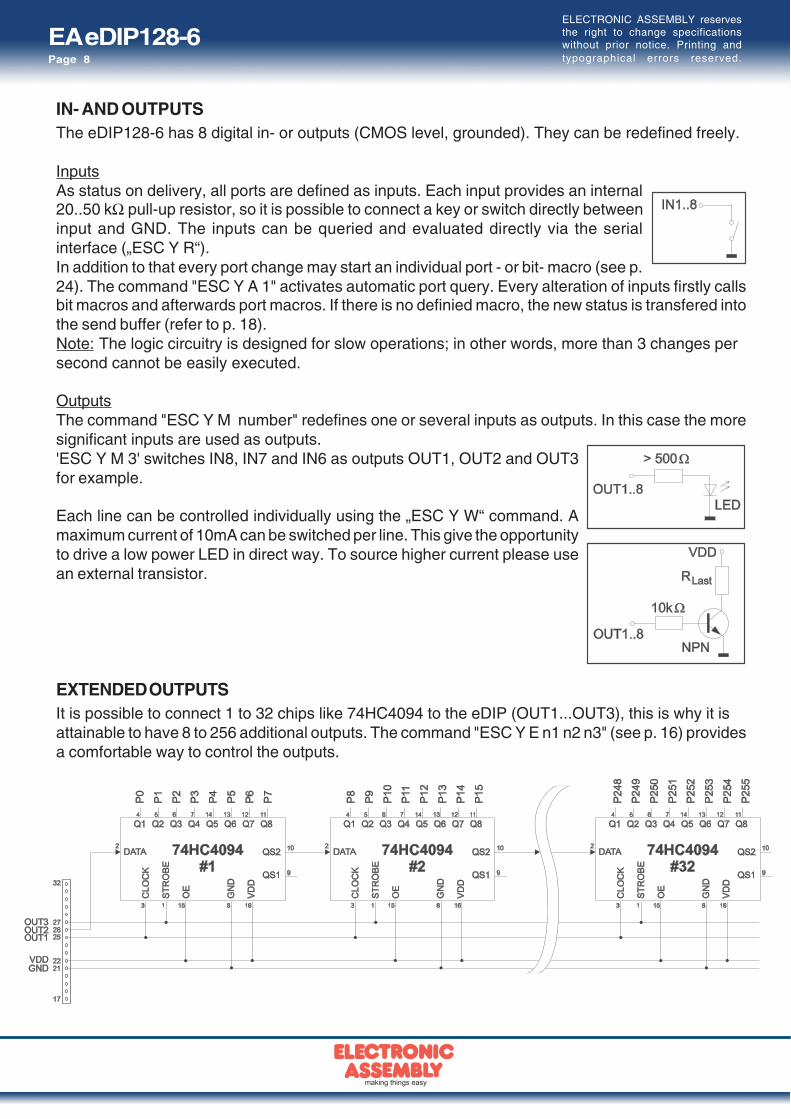
IN- AND OUTPUTSThe eDIP128-6 has 8 digital in- or outputs (CMOS level, grounded). They can be redefined freely.
InputsAs status on delivery, all ports are defined as inputs. Each input provides an internal20..50 kΩ pull-up resistor, so it is possible to connect a key or switch directly betweeninput and GND. The inputs can be queried and evaluated directly via the serialinterface („ESC Y R“).In addition to that every port change may start an individual port - or bit- macro (see p.24). The command "ESC Y A 1" activates automatic port query. Every alteration of inputs firstly callsbit macros and afterwards port macros. If there is no definied macro, the new status is transfered intothe send buffer (refer to p. 18).Note: The logic circuitry is designed for slow operations; in other words, more than 3 changes persecond cannot be easily executed.
OutputsThe command "ESC Y M number" redefines one or several inputs as outputs. In this case the moresignificant inputs are used as outputs.'ESC Y M 3' switches IN8, IN7 and IN6 as outputs OUT1, OUT2 and OUT3for example.
Each line can be controlled individually using the „ESC Y W“ command. Amaximum current of 10mA can be switched per line. This give the opportunityto drive a low power LED in direct way. To source higher current please usean external transistor.
EXTENDED OUTPUTSIt is possible to connect 1 to 32 chips like 74HC4094 to the eDIP (OUT1...OUT3), this is why it isattainable to have 8 to 256 additional outputs. The command "ESC Y E n1 n2 n3" (see p. 16) providesa comfortable way to control the outputs.

EA eDIP128-6Page 9
ELECTRONIC ASSEMBLY reservesthe right to change specificationswithout prior notice. Printing andtypographical errors reserved.
0°: 'ESC DO 0' 90°: 'ESC DO 1' 180°: 'ESC DO 2' 270°: 'ESC DO 3'
TOPVIEW AND TWISTED MOUNTINGThe prefered view of the eDIP128 is bottom view, (6 o'clock).The eDIP can be mounted turned around 180° to gain a top view display (12 o'clock). To set theviewing direction you have to run (e.g. in PowerOnMacro) the command 'ESC DO 2' (refer to p. 13).In addition it is possible to mount the display turned with 90° or 270° to gain a portrait mode displaywith 64x128 pixels.
POWER DOWN MODETo save energy (battery operation), you can activate one of three power-down modes by means of thecommand ‘ESC PD n1’ (see page 15 below).
Mode 0 (25µA): The LED illumination is switched off, and the contents of the display becomeinvisible although they are still there. In power-down mode including suppressordiodes, the eDIP128 requires up to 1000 µA (delivery state). The suppressor diodescan be deactivated by removing the two 0Ω resistors. Then powerdown current oftypically 25 µA is reached. They are labeled with Rpd.Important: When deactivating the suppressor diodes, it is essential that the polarity ofthe display is correct all the time: GND, VDD (pin 1 + 2). Even very brief polarity reversalor overvoltage can damage the display immediately and irreparably.
Mode 1 (1mA): The LED illumination is switched off, the contents of the display stay visible. Currentconsumption is reducing to 1mA. This power down mode is mainly usable with theversions EA eDIP128W with positive display, because they are readable withoutbacklight.
Mode 2 (4mA): The LED illumination stays on and the display content is readable. The currentconsumption reduces to 3-4mA plus adjusted LED current. Therefore you can usethe eDIP in dark surroundings and dimmed illumination under e.g. 10mA.
The eDIP128 can be woken up from power down mode with a low level on pin 13 (WUP), or theadressing via I²C.In additon the eDIP128 can be woke up by using the touchpanel (independed from position).After wake up, special WakeUpMacros can be used (refer to p. 24).
EA eDIP128-6Page 10
ELECTRONIC ASSEMBLY reservesthe right to change specificationswithout prior notice. Printing andtypographical errors reserved.
> <DC1> len data... bcc
< <ACK>
> <DC2> 1 S bcc
< <ACK>
< <DC1> len data... bcc
void SendData(unsigned char *buf, unsigned char len) unsigned char i, bcc;
SendByte(0x11); // Send DC1 bcc = 0x11;
SendByte(len); // Send data length bcc = bcc + len;
for(i=0; i < len; i++) // Send buf SendByte(buf[i]); bcc = bcc + buf[i];
SendByte(bcc); // Send checksum
C-example to send a datapcket
Clear display and draw a line from 0,0 to 127,63
<DC1> len ESC D L ESC G D 0 0 127 63 bcc >$11 $0A $1B $44 $4C $1B $47 $44 $00 $00 $7F $3F $2A
< <ACK>
$06
Example fo a complete datapackage
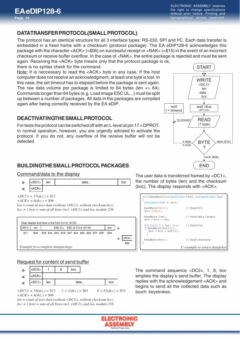
DATA TRANSFER PROTOCOL(SMALL PROTOCOL)The protocol has an identical structure for all 3 interface types: RS-232, SPI and I²C. Each data transfer isembedded in a fixed frame with a checksum (protocol package). The EA eDIP128-6 acknowledges thispackage with the character <ACK> (=$06) on successful receipt or <NAK> (=$15) in the event of an incorrectchecksum or receive buffer overflow. In the case of <NAK>, the entire package is rejected and must be sentagain. Receiving the <ACK> byte means only that the protocol package is ok,there is no syntax check for the command.Note: It is neccessary to read the <ACK> byte in any case. If the hostcomputer does not receive an acknowledgment, at least one byte is lost. Inthis case, the set timeout has to elapsed before the package is sent again.The raw data volume per package is limited to 64 bytes (len <= 64).Commands longer than 64 bytes (e.g. Load image ESC UL...) must be splitup between a number of packages. All data in the packages are compiledagain after being correctly received by the EA eDIP.
DEACTIVATING THE SMALL PROTOCOLFor tests the protocol can be switched off with an L-level at pin 17 = DPROT.In normal operation, however, you are urgently advised to activate theprotocol. If you do not, any overflow of the receive buffer will not bedetected.
Command/data to the display
Request for content of send buffer
BUILDING THE SMALL PROTOCOL PACKAGES
<DC1> = 17(dez.) = $11<ACK> = 6(dez.) = $06len = count of user data (without <DC1>, without checksum bcc)bcc = 1 byte = sum of all bytes incl. <DC1> and len, modulo 256
The user data is transferred framed by <DC1>,the number of bytes (len) and the checksum(bcc). The display responds with <ACK>.
The command sequence <DC2>, 1, S, bccempties the display’s send buffer. The displayreplies with the acknowledgement <ACK> andbegins to send all the collected data such astouch keystrokes.<DC2> = 18(dez.) = $12 1 = 1(dez.) = $01 S = 83(dez.) = $53
<ACK> = 6(dez.) = $06len = count of user data (without <DC1>, without checksum bcc)bcc = 1 byte = sum of all bytes incl. <DC1> and len, modulo 256

EA eDIP128-6Page 11
ELECTRONIC ASSEMBLY reservesthe right to change specificationswithout prior notice. Printing andtypographical errors reserved.
> <DC2> 3 Dpacket size for
send buffer timeout bcc
< <ACK>
> <DC2> 1 R bcc
< <ACK>
<<DC1><DC2>
len data... bcc
> <DC2> 3 A select or deselect adr bcc
< <ACK>
> <DC2> 1 P bcc
< <ACK>
< <DC2> 3 max.packet size
akt. sendpacket size
akt. timeout bcc
> <DC2> 1 I bcc
< <ACK>
< <DC2> 2 send bufferbytes ready
receive bufferbytes free
bcc
<DC2> = 18(dec.) = $12 3 = 3(dez.) = $03 D = 68(dez.) = $44packet size for send buffer = 1..128 (standard: 128)timeout = 1..255 in 1/100 seconds (standard: 200 = 2 seconds)bcc = 1 byte = sum of all bytes incl. <DC2>, modulo 256<ACK> = 6(dec.) = $06
Adressing (only for RS232/RS485)
<DC2> = 18(dez.) = $12 3 = 3(dez.) = $03 A = 65(dez.) = $41select or deselect: 'S' = $53 or 'D' = $44adr = 0..255bcc = 1 byte = sum of all bytes incl. <DC2> and adr, modulo 256<ACK> = 6(dec.) = $06
<DC2> = 18(dez.) = $12 1 = 1(dez.) = $01 R = 82(dez.) = $52<ACK> = 6(dez.) = $06<DC1> = 17(dez.) = $11len = count of user data in byte (without ckecksum, without <DC1> or <DC2>)bcc = 1 byte = sum of all bytes incl. <DC2> and len, modulo 256
If the most recently requested packagecontains an incorrect checksum, the entirepackage can be requested again. The reply canthen be the contents of the send buffer (<DC1>)or the buffer/protocol information (<DC2>).
This is how the maximum package size that canbe sent by the display can be limited. The defaultsetting is a package size with up to 128 bytes ofuser data. The timeout can be set in incrementsof 1/100 seconds. The timeout is activatedwhen individual bytes get lost. The entirepackage then has to be sent again.
This command can be used to select ordeselect the eDIP with the address adr.
Request for protocol settings
<DC2> = 18(dez.) = $12 1 = 1(dez.) = $01 P = 80(dez.) = $50<ACK> = 6(dez.) = $06max. packet size = count of maximum user data for 1 package (eDIP128-6 = 64)akt. send packet size = current package size for sendakt. timeout = current timeout in 1/100 secondsbcc = 1 byte = sum of all bytes incl. <DC2>, modulo 256
This command is used to query protocolsettings.
Request for buffer information
<DC2> = 18(dez.) = $12 1 = 1(dez.) = $01 I = 73(dez.) = $49<ACK> = 6(dez.) = $06send buffer bytes ready = count of bytes stored in send bufferreceive buffer bytes free = count of bytes for free receive bufferbcc = 1 byte = sum of all bytes incl. <DC2>, modulo 256
This command queries whether user data isready to be picked up and how full the display'sreceive buffer is.
Protocol settings
Repeat the last package

EA eDIP128-6Page 12
ELECTRONIC ASSEMBLY reservesthe right to change specificationswithout prior notice. Printing andtypographical errors reserved.
Terminal-Font (Font 0): 8x8 monospaced
TERMINAL MODEWhen you switch the unit on, the cursor flashes in thefirst line, indicating that the display is ready foroperation. All the incoming characters are displayedin ASCII format on the terminal (exception:CR,LF,FF,ESC,’#’). The prerequisite for this is aworking protocol frame (pages 10 and 11) or adeactivated protocol.Line breaks are automatic or can be executed bymeans of the ‘LF’ character. If the last line is full, thecontents of the terminal scroll upward. The ‘FF’character (page feed) deletes the terminal. Thecharacter ‘#’ is used as an escape character and thuscannot be displayed directly on the terminal. If thecharacter ‘#’ is to be output on the terminal, it must betransmitted twice: ‘##’.The terminal has its own level for displaying and is thus entirely independent of the graphic outputs.If the graphics screen is deleted with ‘ESC DL’, for example, that does not affect the contents ofthe terminal window. The terminal font is fixed in the ROM and can also be used for graphic outputs‘ESC Z...’ (set FONT nr=0).
USING THE SERIAL INTERFACEThe operating unit can be programmed by means of various integrated commands. Each commandbegins with ESCAPE followed by one or two command letters and then parameters. There are twoways to transmit commands:1. ASCII mode- The ESC character corresponds to the character ‘#’ (hex: $23, dec: 35).- The command letters follow directly after the ‘#’ character.- The parameters are transmitted as plain text (several ASCII characters) followed by a separating
character (such as a comma ‘,’), also after the last parameter e.g.: #GD0,0,159,103,- Strings (text) are written directly without quotation marks and concluded with CR (hex: $0D) or LF
(hex: $0A).2. Binary mode- The escape character corresponds to the character ESC (hex: $1B, dec: 27).- The command letters are transmitted directly.- The coordinates x and y are transmitted as 8-bit binary values.- All the other parameters are transmitted as 8-bit binary values (1 byte).- Strings (text) are concluded with CR (hex: $0D) or LF (hex: $0A) or NUL (hex: $00).No separating characters, such as spaces or commas, may be used in binary mode.The commands require no final byte, such as a carriage return (apart from the string $00).
FILL PATTERNA pattern type can be set as a parameter with variouscommands. In this way, for example, rectangularareas and bar graphs can be filled with differentpatterns. There are 16 internal fill patterns available.

EA eDIP128-6Page 13
ELECTRONIC ASSEMBLY reservesthe right to change specificationswithout prior notice. Printing andtypographical errors reserved.
Terminal commands AfterresetCommand Codes Remarks
Form feed FF (dec:12) ^L The contents of the screen are deleted and the cursor is placed at pos. (1,1)
Carriage return CR(13) ^M Cursor to the beginning of the line on the extreme left
Line feed LF (dec:10) ^J Cursor 1 line lower, if cursor in last line then scroll
Position cursor
ESC T
P C L C=column; L=line; origin upper-left corner (1,1) 1,1Cursor on/off C n1 n1=0: Cursor is invisible; n1=1: Cursor flashes; 1Save cursor position S The current cursor position is saved
Restore cursor position R The last saved cursor position is restored
Terminal off A Terminal display is switched off; outputs are rejected
Terminal on E Terminal display is switched on; OnOutput version
ESC
T
V The version no. is output in the terminal (e.g. "EA eDIP128-6 V1.0 Rev.A")
Output project name J The macro project name is output to the terminal (e.g. "init / delivery state")
Output information ESC IThe terminal is initialized and deleted; software version, hardware revision, the macroproject name and the CRC-checksum is ouput to the terminal
Display commands (effect the entire display) afterresetCommand Codes Remarks
Set display orientationESC D
O n1 n1=0: 0°; n1=1: 90°; n1=2: 180°; n1=3: 270°; (0°+180°=160x104; 90°+270°=104x160) 0°
Set display contrast K n1n1=0..40: Set display contrast to n1 (default = 20)n1='+': increase contrast; n1='-': decrease contrast
20
Delete display
ESC D
L Delete display contents (all pixels off)
Invert display I Invert display contents (invert all pixels)
Fill display S Fill display contents (all pixels on)
Switch display off A Display content becomes invisible but are retained, commands are still possible
Switch display on E Display content becomes visible again OnShow clipboard C Show content of clipboard; Standard display outputs are no longer visible
Show normal displaycontent
N Normal operation, standard display outputs are visible
Clipboard commands (Buffer for display area) afterresetCommand Codes Remarks
Save display contents
ESC C
B The entire contents of the display are copied to the clipboard as an image area
Save area S x1 y1 x2 y2 The image area from x1,y1 to x2,y2 is copied to the clipboard
Restore area R The image area on the clipboard is copied back to the display
Copy area K x1 y1 The image area on the clipboard is copied to x1,y1 in the display
Change / draw rectangular areas afterresetCommand Codes Remarks
Delete area
ESC R
L x1 y1 x2 y2 Delete an area from x1,y1 to x2,y2 (all pixels off)
Invert area I x1 y1 x2 y2 Invert an area from x1,y1 to x2,y2 (invert all pixels)
Fill area S x1 y1 x2 y2 Fill an area from x1,y1 to x2,y2 (all pixels on)
Area with fill pattern M x1 y1 x2 y2 n1 Fill an area from x1,y1 to x2,y2 with pattern n1 (always set)
Draw box O x1 y1 x2 y2 n1 Draw rectangle from x1,y1 to x2,y2 with pattern n1 (always replace)
Draw frame R x1 y1 x2 y2 n1 Draw frame of type n1 from x1,y1 to x2,y2 (always set)
Draw frame box T x1 y1 x2 y2 n1 Draw frame box of type n1 from x1,y1 to x2,y2 (always replace)
Straight lines and points afterresetCommand Codes Remarks
SettingsPoint size / line thickness
ESC GZ n1 n2 n1 = x-point size (1..15); n2 = y-point size (1..15); 1,1
Graphic link mode V n1 Set drawing mode n1: 1=set; 2=delete; 3=inverse 1Blink attribute ESC G B n1 n1:0=no blink; 1=on/off; 2=blink inverted; 3=off/on (phase shifted) 0
Draw lines and pointsDraw point
ESC G
P x1 y1 Set a point at coordinates x1, y1
Draw straight line D x1 y1 x2 y2 Draw a straight line from x1,y1 to x2,y2
Continue straight line W x1 y1 Draw a straight line from the last end point to x1,y1 0, 0Draw rectangle R x1 y1 x2 y2 Draw four straight lines as a rectangle from x1,y1 to x2,y2
ALL COMMANDS AT A GLANCEThe built-in intelligence allows an easy creation of your individual screen content. Below mentionedcommands can be used either directly via the serial interface (see page 12) or together with theselfdefinable macro.

EA eDIP128-6Page 14
ELECTRONIC ASSEMBLY reservesthe right to change specificationswithout prior notice. Printing andtypographical errors reserved.
Text commands afterresetBefehl Codes Remarks
SettingsSet font
ESC Z
F n1 Set font with the number n1 = 0..15 0Set font zoom factor Z n1 n2 n1 = x-zoom factor (1x..4x); n2 = y-zoom factor (1x..4x) 1,1Additonal line spacing Y n1 Insert n1 = 0..15 dots between two lines as additional spacing 0Spacewidth J n1 Spacewidth: n1=0 use from font; n1=1 same width as number; n1>=2 width in dot 0
Text angle W n1 Text angle: n1=0: 0°; n1=1: 90°; 0Text link mode V n1 Mode n1: 1=set; 2=delete; 3=inverse; 4=replace; 5=inverse replace 4Text flashing attribute ESC Z B n1 n1:0=no flashing; 1=on/off; 2=flash inversly; 3=off/on (phase shifted) 0
Output strings
Output stringL: left justifiedC: centeredR: right justified
ESC Z
L
x1 y1Text...
NUL
A string is output to x1,y1; string termination is: 'NUL' ($00), 'LF' ($0A) or 'CR' ($0D);several lines are seperated by the character '|' ($7C);Text between two '~' ($7E): characters flashes on/off;Text between two '&' ($26): characters flashes phase shifted;Text between two '@' ($40): characters flashes inverse;The character '\' ($5C, backslash) cancels the special funtion of characters '|~@\';e.g. "name\@test.de" => "[email protected]"
C
R
String for terminal ESC Z T Text ... Command to output a string (text...) from a macro to the terminal
Bitmap commands afterresetCommand Codes Remarks
SettingsImage zoom factor
ESC U
Z n1 n2 n1 = x-zoom factor(1x..4x); n2 = y-zoom factor (1x..4x) 1,1Image angle W n1 Image angle: n1=0: 0°; n1=1: 90° 0Image link mode V n1 Mode n1: 1=set; 2=delete; 3=inverse; 4=replace; 5=inverse replace; 4Image flashing attribute ESC U B n1 n1:0=no flashing; 1=on/off; 2=flash inverted; 3=off/on (phase shifted) 0
OutputImage from clipboard
ESC U
C x1 y1 The current contents of the clipboard are loaded to x1,y1 with all the image attributes
Load internal image I x1 y1 nr Load internal image with nr (0..255) from EEPROM to x1,y1
Load image L x1 y1 BLH data ... Load an image to x1,y1; data... = image in BLH-format
Hardcopy
Send hardcopy ESC U H x1 y1 x2 y2 An image area x1,y1 to x2,y2 is put into the sendbuffer. The image is send in BLH-format
Bargraph commands afterresetCommands Codes Remarks
Definition
Define bargraph ESC B
RLOU
n1 x1 y1 x2 y2 aw ew type pat
Define bargraph with number n1=1..32 to l(eft), r(ight), o(up), u(down).x1,y1,x2,y2 are the surrounding rectangle of the bar. aw,ew are the values fo0% and 100%.type=0:pattern bar; type=1:pattern bar in rectangle; pat=bar patterntype=2:line bar; type=3:line bar in rectangle; pat=line width
no bardefined
Delete bargraph ESC B D n1 n2The definition of bargraph n1 becomes invalid. If the bargraph was defined as an input by touch, thetouch field will also be deletedn2=0: Bargraph remains visible; n2=1: Bargraph is deleted
UseUpdate bargraph
ESC BA n1 val Set and draw the bargraph n1 to new val(ue).
Redraw bargraph Z n1 Entirely redraw the bargraph n1.
Send bargraph value S n1 Send the current value of the bargraph number n1
Flashing commands afterresetCommand Codes Remarks
SettingsSet flashing time ESC Q Z n1 Set flashing time to n1= 1..15 in 1/10s; 0=flashing deactivated 6
Flashing areas
Delete flashing attribute
ESC Q
L x1 y1 x2 y2 Delete the flashing attribute from x1,y1 to x2,y2. Do not use this command for phase shiftedareas! (Copies the area from graficlayer to blinklayer)
Flashing inversely I x1 y1 x2 y2 Define an inverted flashing area from x1,y1 to x2,y2. (Copies the inverted area from graficlayerto blinklayer)
Flashing area pattern M x1 y1 x2 y2 n1Define a flashing area (on/off) with pattern n1 frim x1,y1 to x2,y2 (Draw the pattern intoblinklayer)
Phase shifted areas
Restore phase shifted area
ESC Q
R x1 y1 x2 y2Delete the phase shifted flashing area from x1,y1 to x2,y2. Do not use this command for otherflashing attributes! (Copies the area from blinklayer to graphiklayer)
Inverted phase shifted area E x1 y1 x2 y2 Define a phase shifted inverted flashing area from x1,y1 to x2,y2. (Copies the inverted are fromblinklayer to graphiklayer)
Phase shifted flashingpattern
P x1 y1 x2 y2 n1 Define a phase shifted flashing area (off/on) with pattern n1 from x1,y1 to x2,y2. (Draw thepattern into graficlayer)

EA eDIP128-6Page 15
ELECTRONIC ASSEMBLY reservesthe right to change specificationswithout prior notice. Printing andtypographical errors reserved.
Menu commands afterresetCommand Codes Remarks
Settings for menu box/touch menuSet menu font
ESC N
F n1 Set font with the number n1 (0 to 15) for menu display 0Menu font zoom factor Z n1 n2 n1 = x-zoom factor (1x..4x); n2 = y-zoom factor (1x..4x) 1,1Additional line spacing Y n1 Insert n1 (0..15) dots between two menu items as additional spacing
Menu angle W n1 Menu display angle: n1=0: 0°; n1=1: 90°; 0
Touch menu automation T n1n1=1: Touchmenu opens automatically;n1=0: Touchmenu doesn't open automatically, instead the rquest 'ESC T0' is sent to the host,which can then open the touch menu with 'ESC NT2'
1
Menu box commands (control not by touch)
Define and display menu
ESC N
D x1 y1 nr Text...
NUL
A menu is drawn at the corner x1,y1 witch the current font of menunr:= currently inverted entry (e.g. 1 = first entry)Text...:= string with menu items. The different items are seperated by the character'|' ($7C,dez:124) e.g. "Item1|Item2|Item3"The background of the menu is automatically saved into the clipboard (previous contend will beoverwritten).If a menu is already defined, it is automatically canceled and deleted
Next item N The next item is inverted or remains at the end
Previous item P The previous item is inverted or remains at the beginning
End of menu/send SThe menu is removed and replaced with the original background. The current item is sent as anumber (1 to n; 0 = no menu displayed)
End of menu/macro M n1The menu is removed and replaced with the original background. Menu macro n1 is called foritem 1, menu macro n1+1 for item 2 and so on... .
End of menu/cancel A The menu is removed and replaced with the original background
Macro commands afterresetCommand Codes Remarks
Call macrosRun normal macro
ESC M
N n1 Call the (normal) macro with the number n1 (max. 7 levels)
Run touch macro T n1 Call the touch macro with the number n1 (max. 7 levels)
Run menu macro M n1 Call the menu macro with the number n1 (max. 7 levels)
Run port macro P n1 Call the port macro with the number n1 (max. 7 levels)
Run bit macro B n1 Call the bit macro with the number n1 (max. 7 levels)
automatic (normal-) macros
Macro with delay
ESC M
G n1 n2Call the (normal) macro with the number n1 in n2/10s. Execution is stopped by commands (e.g.receipt or touch macros)
Automatic macros onceonly
E n1 n2 n3 Automatically run macros n1 to n2 once only; n3 = pause in 1/10s. Execution is stoppedby commands (e.g. receipt or touch macros)
Automatic macros cyclically A n1 n2 n3 Automatically run macros n1 to n2 cyclically; n3 = pause in 1/10s. Execution is stopped bycommands (e.g. receipt or touch macros)
Automatic macros pin pong J n1 n2 n3 Automatically run macros n1 to n2 to n1 (ping pong); n3 = pause in 1/10s. Execution is stopped bycommands (e.g. receipt or touch macros)
Macro processes
Define macro process
ESC M
D no type n3 n4 zsA macro process with the number no (1 to 4) is defined (1=highest priority). The macros n3 ton4 are run successuvely every zs/10s.Type: 1=once only; 2=cyclical; 3=ping pong n3 to n4 to n3
Macro process interval Z no zsA new time zs/10s is assigned to the macro process no (1 to4). If the time zs is set to 0, theexecution is stopped.
Stop macro processes S n1All macro processes are stopped with n1=0 and restarted with n1=1 in order, for example, toexecute settings and outputs via the interface undisturbed.
1
General commands afterresetCommand Codes Remarks
BacklightIllumination brightness
ESC Y
H n1 Set brightness of the LED illumination to n1=0%..100% 100
Brightness changetime Z n1 Time n1=0..31 in 1/10s for changing brightness from 0% to 100% 5
Illumination on/off L n1 LED illumination n1=0: off; n1=1: on; n1=2 to 255: The illumination is switched on for n1/10s. 1
Save parameter @ Save actual brightness and changetime parameter for power on to EEPROM
Send commands
Send bytes
ESC S
B len data ...len (=1 to 255) bytes are sent to the sendbuffer data... = data to send. In the source text of themacro programming, the number len must not be specified. This is counted by theediptft-compiler and entered.
Send version V The version is sent as a string to sendbuffer, e.g. "EA eDIP128-6 V1.0 Rev.A TP+"
Send projectname J The macro project name is sent as a string to sendbuffer, e.g. "init / delivery"
Send internal infos I Internal information about the eDIP is sent to the sendbuffer
Other commandsWait (pause) ESC X n1 Wait n1/10s before next command is executed
Set RS485 address ESC K A adrFor RS232/RS485 operation only and only possible when Hardware address is 0. The eDIP isassigned a new address adr (in the Power-On-Macro).
Buzzer output ESC Y S n1 The buzzer output (pin 16) becomes n1=0:OFF; n1=1:ON; n1=2 to 255:ON for n1/10s OFF
Power down ESC P D n1 n2After this command, the display goes into power-down mode n1=0..2 (see page 9).n2=0: no wake-up by touch; n2=1: wake-up by touch possible

EA eDIP128-6Page 16
ELECTRONIC ASSEMBLY reservesthe right to change specificationswithout prior notice. Printing andtypographical errors reserved.
I/O-Ports afterresetCommand Codes Remarks
Input ports
Read input port
ESC Y
R n1 n1=0: Read all input ports as binary value (to sendbuffer)n1=1..8: Read input port n1
Port scan on/off A n1 The automatic scan of the input port is n1=0 deactivated, n1=1 activated 1
Invert input port I n1 The input port is n1=0 is evaluated normal, n1=evaluated inverted 0
Redefine input bitmacro D n1 n2 n3 Input port n1=1..8 is assigned by falling edge n2=0 to BitMacro n3=0..255Input port n1=1..8 is assigned by rising edge n2=1 to BitMacro n3=0..255
Output ports
Define output portESC Y
M n1n1=0: All 8 I/O-Ports are inputs IN1..IN8 (=default after Power-On / Reset)n1=1..8: n1 I/O-lines will be set to output (beginninge at OUT1 upwards) 0
Write output port W n1 n2n1=0: Set all defined output ports in accordance with n2 (=binary value)n1=1..8: Reset output port n1 (n2=0); set (n2=1); invert (n2=2)
Port expansion with 74HC4094
Write extended ports ESC Y E n1 n2 n3 Set the outputs of the external 74HC4094 (refer to page 8) from port n1=0..255 to portn2=0..255; n3=0: low; n3=1: high; n3=2: invert
TOUCH PANEL (ONLY EA eDIP128x-6xxTP)
The -xxxTP versions are shipped with an analog, resistive touch panel. Up to 40 touchareas (keys, switches, menus, bar graph inputs) can be defined simultaneously. Thefields can be defined with pixel accuracy. The display supports user-friendlycommands (see page 17). When the touch “keys” are touched, they can beautomatically inverted and an external tone can sound (pin 16), indicating they havebeen touched. The predefined return code of the “key” is transmitted via the interface,or an internal touch macro with the number of the return code is started instead (seepage 22, Macro programming).
FRAMES AND KEY SHAPESA frame type can be set by using the Draw frame or Draw frame box command or bydrawing touch keys. 18 frame types are available (0 = do not draw a frame). The framesize must be at least 16x16 pixels.
BITMAPS AS KEYSApart from the frame types, which are infinitely scalable, it is also possible to usebitmaps (2 each, for not printed and printed) as touch keys or touch switches. You canuse ELECTRONIC ASSEMBLY LCD-Tools*) to integrate your own buttons as images(“PICTURE” compiler statement). A button always consists of two monochromeWindows BMPs of equal size (one bitmap to display the touch key in its normal stateand one for when it is pressed). The active area of the touch key automatically resultsfrom the size of the button bitmaps.
SWITCHES IN GROUPS (RADIO GROUP)Touch switches (radio buttons) change their status from ON toOFF or vice versa each time they are touched. Several touchswitches can be included in a group (‘ESC A R nr’ command).If a touch switch in the group ‘nr’ is switched on, all the othertouch switches in this group are automatically switched off.Only one switch is ever on.

EA eDIP128-6Page 17
ELECTRONIC ASSEMBLY reservesthe right to change specificationswithout prior notice. Printing andtypographical errors reserved.
Commands for the touch panel afterresetCommand Codes Remarks
SettingsTouch frame ESC A E n1 The frame type for the display of touch keys/switches is set with n1 1
Radio group for switches ESC A R nr
Only 1 switch in a group is active at any one time; all the others are deactivated. nr=0: newlydefined switches do not belong to a group. nr=1 to 255: newly defined switches belong to thegroup with the number nr. In the case of a switch in a group, only the down code is applicable.the up code is ignored.
0
Touch: Label fontLabel font
ESC A
F nr Set font with the number n1 (0 to 31) for touch key label 0Label zoom factor Z n1 n2 n1 = X zoom factor (1x to 8x); n2 = Y zoom factor (1x to 8x) 1,1Add. line spacing Y n1 Insert n1 pixels (0 to 15) between two lines of text as additional line spacing
Label angle W n1 Text output angle: n1=0: 0°; n1=1: 90°; n1=2: 180°; n1=3: 270° 0
Touchbereiche definieren
Define touch key (keyremains depressed as longas there is contact)
ESC A
T x1 y1 x2 y2 dowCod
upCod
Text...
NUL
'T': The area from x1,y1 to x2,y2 is defined as a key. 'U': Image no. n1 isloaded to x1,y2 and defined as a key. 'down code':(1-255) Return/touchmacro when key pressed. 'up code': (1-255) Return/touch macro when keyreleased. (down/up code = 0 press/release not reported). ´text´: the firstcharacter determines the alignment of the text (C=centered, L=left justified,R=right justified). this is followed by a string that is placed in the key with thecurrent touch font. multiline texts are separated with the character '|' ($7C,dec: 124); 'nul': ($00) = end of string
U x1 y1 n1 dowCod
upCod
Text... NUL
Define touch switch (statusof the switch toggles aftereach contact)
ESC A
K x1 y1 x2 y2 dowCod
upCod
Text...
NUL
'K': The area from x1,y1 to x2,y2 is defined as a switch. 'J': Image no. n1is loaded to x1,y2 and defined as a switch. 'down code': (1-255)Return/touch macro when switched on. 'up code': (1-255) Return/touch macrowhen switched off. (down/up code = 0 on/off not reported). ´text´: the firstcharacter determines the alignment of the text (C=centered, L=left justified,R=right justified). this is followed by a string that is placed in the key with thecurrent touch font. multiline texts are separated with the character '|' ($7C,dec: 124); 'nul': ($00) = end of string
J x1 y1 n1 dowCod
upCod
Text... NUL
Define touch key with menufunction
ESC A M x1 y1 x2 y2 dowCod
upCod
mnuCod
Text...
NUL
The area from x1,y1 to x2,y2 is defined as a menu key. 'downcode':(1-255) Return/touch macro when pressed. 'up Code':(1-255)Return/touch macro when menu canceled 'mnu Code':(1-255)Return/menu macro+(item no. 1) after selection of a menu item.(down/up code = 0: activation/cancellation is not reported.) 'text':= stringwith the key text and the menu items. the first character determines thedirection in which the menu opens (R=right, L=left, O=up, U=down). Thesecond character determines the alignment of the touch key text(C=centered, L=left justified, R=right justified). The menu items areseparated by the character '|' ($7C,dec:124) (e.g."uckey|item1|item2|item3". The key text is written with the current touchfont and the menu items are written with the current menu font. Thebackground of the menu is saved automatically.
Define drawing area ESC A D x1 y1 x2 y2 n1A drawing area is defined. You can then draw with a line width of n1 within the cornercoordinates x1,y1 and x2,y2.
Define free touch area ESC A H x1 y1 x2 y2A freely usable touch area is defined. Touch actions (down, up and drag) within the cornercoordinates x1,y1 and x2,y2 are sent.
Set bar by touch ESC A B nr The bar graph with the no. n1 is defined for input by touch panel.
Global settingsTouch query on/off ESC A A n1 Touch query is deactivated (n1=0) or activated (n1=1); 1
Touch key response ESC AI n1 Automatic inversion when touch key touched: n1=0=OFF; n1=1=ON; 1S n1 Tone sounds briefly when a touch key is touched: n1=0=OFF; n1=1=ON 1
Send bar valueautomatically
ESC A Q n1The Automatic transmission of a new bar graph value by touch input is deactivated (n1=0);a new value is sent after setting (n1=1); each change is sent during setting (N1=2).
1
Other commandsInvert touch key
ESC A
N Cod The touch key with the assigned return code is inverted manually
Set touch switch P Cod n1 The status of the switch is changed by means of a command (n1=0=off; n1=1=on).
Query touch switch X Cod The status of the switch (off=0; on=1) is placed in the send buffer.
Query radio group G nr The down code of the activated switch from radio group nr is placed in the sendbuffer
Delete touch area ESC AL Cod n1
The touch area with the return code (code=0: all touch areas) is removed from the touch query.When n1=0, the area remains visible on the display; when n1=1, the area is deleted.
V x1 y1 n1Remove the Touch area that includes the coordinates x1,y1 from the touch query. n1=0: arearemains visible; n1=1: Delete area
ADJUST TOUCHPANELThe touch panel is perfectly adjusted and immediately ready for operation on delivery. As a result ofaging and wear, it may become necessary to readjust the touch panel.Adjustment procedure:1. Touch the touch panel at power-on and keep it depressed. After the message “touch adjustment?”
appears, release the touch panel again (or issue the ‘ESC @’ command).2. Touch the touch panel again within a second for at least a second.3. Follow the instructions for adjustment (press the 2 points upper left and lower right).

EA eDIP128-6Page 18
ELECTRONIC ASSEMBLY reservesthe right to change specificationswithout prior notice. Printing andtypographical errors reserved.
Responses of the eDIPId num data Remarks
automatic responses (placed into sendbuffer)
ESC A 1 code Response from the analog touch panel when a key/switch is pressed. code = down or up code of the key/switch. It isonly transmitted if no touch macro with the number code is defined !
ESC B 2 no value When a bargraph is set by touch, the current value of the bar no is transmitted. Transmission of the bar balue must beactivated (see the 'ESC A Q n1' command).
ESC N 1 code After a menu item is selcted by touch, the selected menu item code is transmitted. It is only transmitted if no touchmacro is defined with the number code.
ESC T 0 If automatic opening of a touch menu is disabled (see 'ESC NT n1'), this request is sent to the host computer. The hostcan then open the touch menu with the 'ESC N T 2' command.
ESC P 1 value After the input port is changed, the new 8-bit value is transmitted. The automatic port scan must be activated. See the'ESC Y A n1' command. It is only transmitted when there is no corresponding port/bit macro defined !
ESC H 5 type xLO xHI yLO yHI The following is transmitted in the case of a free touch area event: type=0 is release; type=1 is touch; type=2 is dragwithin the free touch area at the coordinates x1, y1
Response only when requested by command (placed into sendbuffer)ESC N 1 no After the 'ESC N S' command, the currently selected menu item is transmitted. no=0, no menu item is selectedESC B 2 no value After the 'ESC B S n1' command, the current value of the bar with the number no is transmitted.ESC X 2 code value After the 'ESC A X' command, the current status (value=0 or 1) of the touch switch code is transmitted.
ESC G 2 no code After the 'ESC A G nR' command, the code of the active touch switch in the radio group no is sent.
ESC Y 2 no valueAfter the 'ESC Y R' command, the requested input port is transmitted. no=0: value is an 8-bit binary value of all 8 inputs.no=1..8: value is 0 or 1 depending on the status of the input no
ESC V num version string...After the 'ESC S V' command, the version of the edip firmware is transmitted as a stringe.g. "EA eDIP128-6 V1.0 Rev.A TP+"
ESC J num projectname string... After the 'ESC S J' command, the macro-projectname is transmitted. e.g. "init / delivery state"
ESC I 21
X-dots, Y-dots, Version, Touchinfo,CRC-ROM, CRC-ROMsoll
DF in KB,CRC-DF, CRC-DFsoll, DFlen
after the 'ESC S I' command, internal information is sent by eDIP (16-Bit integer values LO-HI Byte)Version: LO-Byte = version number Software; HI-Byte = Hardware revison letter touchTouchinfo: LO-Byte = '-|+' X direction detected; HI-Byte = '-|+' Y direction detectedDFlen: number of user bytes in data flash memory (3 Bytes: LO-, MID- HI-Byte)
Responses without length specification (num)
ESC U L x1 y1imagedata...(G16-F
after the 'ESC UH....' command, a hard copy is sent in BLH Format. x1,y1 = Start coordinates of the hard copy (upper lefcorner)BLH-Data: 2 Byte: Width, height (in Pixel)+ amount of bytes of image dataamount = ((width+7)/8*height
RESPONSES OF THE EA EDIP128-6 VIA SERIAL INTERFACEThe table below contains all response codes. Some response data will come automatically someothers on request. In addition to that with command 'ESC SB ...' user is able to transmit individual datapackages. All reponses are placed into the sendbuffer. With the smallprotocol command ’Request forcontent of send buffer’ (see page10) the host can read out the sendbuffer. This can be done per polling,alternatively pin 20 ’SBUF’ shows with Low-level that data is ready to transmit.

EA eDIP128-6Page 19
ELECTRONIC ASSEMBLY reservesthe right to change specificationswithout prior notice. Printing andtypographical errors reserved.
Font 1: 4x6 monospaced
Font 2: 6x8 monospaced
Font 3: 7x12 monospaced
Font 4: GENEVA10 proportionalFont 7: grosse Ziffern BigZif57
PRELOADED FONTSApart from the 8x8 terminal font (font no. 8), 3 additional monospaced fonts, 3 proportional fonts and 1 largenumeric font are integrated as standard. The proportional fonts result in a more attractive appearance, and atthe same time require less space on screen (e.g. the “i” is narrow and the “W” is wide). Each character canbe positioned with pixel accuracy and the width and height can be scaled. Each text can be output left justified,right justified or centered. 90° rotation is also possible. Macroprogramming permits additional fonts to be integrated (up to15). This is done using the LCD-Tools*) (EA 9777-2USB).
EA eDIP128-6Page 20
ELECTRONIC ASSEMBLY reservesthe right to change specificationswithout prior notice. Printing andtypographical errors reserved.
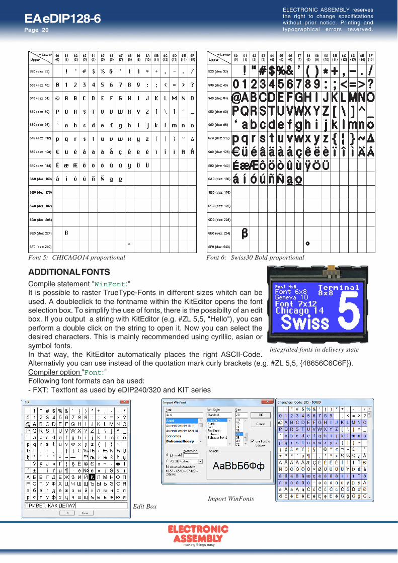
Font 5: CHICAGO14 proportional Font 6: Swiss30 Bold proportional
integrated fonts in delivery state
Import WinFontsEdit Box
ADDITIONAL FONTSCompile statement "WinFont:"It is possible to raster TrueType-Fonts in different sizes whitch can beused. A doubleclick to the fontname within the KitEditor opens the fontselection box. To simplify the use of fonts, there is the possibilty of an editbox. If you output a string with KitEditor (e.g. #ZL 5,5, "Hello"), you canperform a double click on the string to open it. Now you can select thedesired characters. This is mainly recommended using cyrillic, asian orsymbol fonts.In that way, the KitEditor automatically places the right ASCII-Code.Alternativly you can use instead of the quotation mark curly brackets (e.g. #ZL 5,5, 48656C6C6F).Compiler option "Font:"Following font formats can be used:- FXT: Textfont as used by eDIP240/320 and KIT series

EA eDIP128-6Page 21
ELECTRONIC ASSEMBLY reservesthe right to change specificationswithout prior notice. Printing andtypographical errors reserved.
DISPLAY BLINK MODEAfter power on or the command 'ESC DG 0' the eDIP128 is in blink mode.Two picture contents are alternatly shown in an adjustable period.
Blink attributs are set by the commands 'ESC ZB, UB, GB n1':n1=0: no blinkn1=1: On/Off blinkn1=2: blink invertedn1=3: Off/On blink (phase shifted)
Between strings ('ESC ZL,ZC,ZR. ..), flashing can be activated locally:Strings between two ‘~’ ($7E) mean blink on/off.Strings between two ‘&’ ($26) mean blink off/on phase shifted.Strings between two '@' ($40) mean blink inverted.
In addition you can assign or delete postly an rectangle area a blink mode, by using the command'ESC Q...'

EA eDIP128-6Page 22
ELECTRONIC ASSEMBLY reservesthe right to change specificationswithout prior notice. Printing andtypographical errors reserved.
MACRO PROGRAMMING
Single or multiple command sequences can be grouped together in macros and stored in the dataflash memory. You can then start them by using the Run macro commands. There are different typesof macro (compiler directive marked in green letters):Normal macro Macro:These are started by means of an ‘ESC MN xx’ command via the serial interface or from anothermacro. A series of macros occurring one after the other can be called cyclically (movie, hourglass,multi-page help text). These automatic macros continue to be processed until either a command isreceived via the interface or a touch macro with a corresponding return code is activated.
Touch macro TouchMacro:Started when you touch/release a touch field (only in versions with a touch panel - TP) or issue an‘ESC MT xx’ command.Menu macro (1 to 255) MenuMakro:Started when you choose a menu item or issue an ‘ESC MM xx’ command.Bit macro BitMacro:
will be started by a single line IN 1..8 (bit) will change or by command 'ESC MB xx'. Bit- Macro 1..8 aregood for falling edge and Bit Macro 9..16 are good for rising edge at input 1..8. It is possible to changethe assignment between Bitmacro and intput with command ‘ESC YD n1 n2 n3’ (see page 17).Port macro PortMacro:
These are started when voltage (binary) is applied to IN 1..8 or by command 'ESC MP xx'.Power-on-macro PowerOnMacro:Started after power-on. You can switch off the cursor and define an opening screen, for example.Reset-macro ResetMacro:Started after an external reset (low level at pin 5).
Watchdog-macro WatchdogMacro:Started after a fault/error (e.g. failure).Brown-out-macro BrownOutMacro:Started after a voltage drop under 3.0V (typ.).Wake-up-pin-macro WakeupPinMacro:Started after wake up from power-down-mode with pin13 (WUP).Wake-up touch-Macro WakeupTouchMacro:Started after wake up from power-down-mode withtouch (the whole touch area is active).
Wake-up I2C-Macro WakeupI2CMacro:Started after wake up from power-down-mode with the I²C bus.
Important: If a continuous loop isprogrammed in a power-on, reset, watchdogor brown-out macro, the display can nolonger be addressed. In this case, theexecution of the power-on macro must besuppressed. You do this by wiring DPOM:- PowerOff - connect pin 13 (DPOM) to GND- PowerOn - open pin 13 (DPOM) again.

EA eDIP128-6Page 23
ELECTRONIC ASSEMBLY reservesthe right to change specificationswithout prior notice. Printing andtypographical errors reserved.
*) im Internet unter http://www.lcd-module.de/deu/dip/edip.htm
STORING IMAGES IN THE DATA FLASH MEMORYTo reduce the transmission times of the interface or to save storage space in the processor system,up to 256 images can be stored in the internal EEPROM with the “PICTURE” compiler directive. Theycan be called using the “ESC U I” command or from within a macro.All images in the Windows BMP format (monochrome images only) can be used. They can be createdand edited using widely available software such as Windows Paint or Photoshop or the bitmap editorshipped with the product.
CREATING INDIVIDUAL MACROS AND IMAGESTo create your own fonts, images, animations and macros you need the following:- To connect the display to the PC, you need the EA 9777-2USB USB evaluation board, which is
available as an accessory, or a self-built adapter with a MAX232 level converter (see the applicationexample on page 5).
- ELECTRONIC ASSEMBLY LCD-Tools*), which contains a kiteditor, bitmapeditor, ediptftcompiler,fonts, images, border, pattern and examples (for Windows PCs)
- A PC with an USB or serial COM interfaceTo define a sequence of commands as a macro, all the commands are written to a file on the PC (e.g.DEMO.KMC). You specify which character sets are to be integrated and which command sequencesare to be in which macros. If the macros are defined using the kit editor, you start the eDIP compilerusing F5. This creates a file called DEMO.EEP. If an EA 9777-2USB evaluation board is alsoconnected or the display is connected to the PC via a MAX232, this file is automatically burned in thedisplay’s data memory.You can send the created macrofile *.EEP with any other system to the EA eDIP128-6. Allprogramming commands are inside this file, so you only need to send the content of the *.df file (viaRS232, SPI or I2C with smallprotocol in packets) to the EA eDIP128-6.
KIT-EDITOR HELP (ELECTRONIC ASSEMBLY LCD TOOLS)At bottom from the KitEditor window in the statusline you can see a short description for the currentcommand and the parameters. For more information press F1.

EA eDIP128-6Page 24
ELECTRONIC ASSEMBLY reservesthe right to change specificationswithout prior notice. Printing andtypographical errors reserved.
Characteristics
Value Condition min. typ. max. Unit
Operating Temperature -20 +70 °C
Storage Temperature -30 +80 °C
Storage Humidity < 40°C 90 %RH
Operating Voltage 3.2 5.2 V
Input Low Voltage -0.5 0.2*VDD V
Input High Voltage Pin Reset only 0.9*VDD VDD+0.5 V
Input High Voltage except Reset 0.6*VDD VDD+0.5 V
Input Leakage Current 1 uA
Input Pull-up Resistor 20 50 kOhms
Output Low Voltage 0.7 V
Output High Voltage VDD = 3,3VVDD = 5V
2.54.2
V
Output Current 20 mA
Current Backlight onVDD = 3,3VVDD = 5V
210130
mA
Current Backlight offVDD = 3,3VVDD = 5V
1017
mA
Power Down Mode 0 25 µA
SPECIFICATION AND ELECTRICAL CHARACTERISTICS

EA eDIP128-6Page 25
ELECTRONIC ASSEMBLY reservesthe right to change specificationswithout prior notice. Printing andtypographical errors reserved.
MOUNTING BEZEL EA 0FP130-6SWAs accessory we deliver an optional black anodized mounting bezel. The mounting clips are includedin the supplied EA eDIP128-6.
all dimensions are in mm
NOTES ON HANDLING AND OPERATION- The module can be destroyed by polarity reversal or overvoltage of the power supply; overvoltage,
reverse polarity or static discharge at the inputs; or short-circuiting of the outputs.- It is essential that the power supply is switched off before the module is disconnected. All inputs must
also be deenergized.- The display and touch screen are made of plastic and must not come into contact with hard objects.
The surfaces can be cleaned using a soft cloth without solvents.- The module is designed exclusively for use in buildings. Additional measures have to be taken if it
is to be used outdoors. The maximum temperature range of -20 to +70°C must not be exceeded. Ifused in a damp environment, the module may malfunction or fail. The display must be protected fromdirect sunshine.

EA eDIP128-6Page 26
ELECTRONIC ASSEMBLY reservesthe right to change specificationswithout prior notice. Printing andtypographical errors reserved.
NOTES

EA eDIP128-6Page 27
ELECTRONIC ASSEMBLY reservesthe right to change specificationswithout prior notice. Printing andtypographical errors reserved.
NOTES

EA eDIP128-6Page 28
Zeppelinstr. 19 · D-82205 Gilching · Phone +49-(0)8105-778090 · Fax +49-(0)8105-778099 · www.lcd-module.de · [email protected]
ELECTRONIC ASSEMBLY reservesthe right to change specificationswithout prior notice. Printing andtypographical errors reserved.
DIMENSION ATTENTION
handling precautions!
FG: Connection between metalframe and GND (special ESD / EMVconditions)
Note:LC displays are generally not suitedto wave or reflow soldering.Temperatures of over 80°C cancause lasting damage.
Two mounting clips are included.
all dimensions are in mm