operating systems - memory management
TRANSCRIPT

Operating System Unit-3 Memory Management NR-10 Virtual Memory
Mukesh Chinta Asst Prof, CSE, VRSEC 1
Memory Management: Background, Logical Vs. Physical Address space, Swapping,
Contiguous Allocation, Paging, Segmentation, Segmentation with paging.
Virtual Memory: Background, Demand Paging, Performance of Demand Paging, Page
Replacement, Page Replacement Algorithm, Allocation of frames, Thrashing,, Other
Consideration, Demand Segmentation
The memory management subsystem is one of the most important parts of the operating
system. Memory needs to be allocated to ensure a reasonable supply of ready processes to
consume available processor time.
Memory is central to the operation of a modern computer system. Memory consists of a large
array of bytes or words, each with its own address. The CPU fetches instructions from memory
according to the value of the program counter.
A typical instruction execution cycle first fetches an instruction from memory. The
instruction is then decoded and may cause operands to be fetched from memory. After the
instruction has been executed on the operands, results may be stored back in memory. The
memory unit sees only a stream of memory addresses.
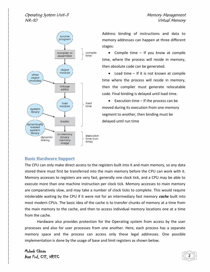
Address Binding
The collection of processes on the disk that’s waiting to be brought into memory for
execution forms the input queue. The normal procedure is to select one of the processes in the
input queue and to load that process into memory. As the process is executed, it accesses
instructions and data from memory. Eventually, the process terminates, and its memory space
is declared available.
A user program goes through the following the steps before getting executed. Addresses may
be represented in different ways during these steps. Addresses in the source program are
symbolic. A compiler will bind these symbolic addresses to relocatable addresses. The linkage
editor or loader will in turn bind the relocatable addresses to absolute addresses. Each binding
is a mapping from one address space to another.
Operating System Unit-3 Memory Management NR-10 Virtual Memory
Mukesh Chinta Asst Prof, CSE, VRSEC 2
Address binding of instructions and data to
memory addresses can happen at three different
stages:
Compile time – If you know at compile
time, where the process will reside in memory,
then absolute code can be generated.
Load time – If it is not known at compile
time where the process will reside in memory,
then the compiler must generate relocatable
code. Final binding is delayed until load time.
Execution time – If the process can be
moved during its execution from one memory
segment to another, then binding must be
delayed until run time
Basic Hardware Support
The CPU can only make direct access to the registers built into it and main memory, so any data
stored there must first be transferred into the main memory before the CPU can work with it.
Memory accesses to registers are very fast, generally one clock tick, and a CPU may be able to
execute more than one machine instruction per clock tick. Memory accesses to main memory
are comparatively slow, and may take a number of clock ticks to complete. This would require
intolerable waiting by the CPU if it were not for an intermediary fast memory cache built into
most modern CPUs. The basic idea of the cache is to transfer chunks of memory at a time from
the main memory to the cache, and then to access individual memory locations one at a time
from the cache.
Hardware also provides protection for the Operating system from access by the user
processes and also for user processes from one another. Here, each process has a separate
memory space and the process can access only these legal addresses. One possible
implementation is done by the usage of base and limit registers as shown below.

Operating System Unit-3 Memory Management NR-10 Virtual Memory
Mukesh Chinta Asst Prof, CSE, VRSEC 3
The base register holds the smallest legal physical memory address and the limit register
specifies the range. Here, the CPU hardware compares every address generated in user mode
with the registers. Any attempt by a program executing in user mode to access OS memory or
other users memory results in a trap to the Operating System, which treats it as a fatal error.
Also, only the OS can load the limit and base register using a special privileged instruction that
can only be executed in kernel mode thereby preventing user programs from changing the
registers contents.
Logical versus Physical Address Space
An address generated by the CPU is referred to as logical address whereas an address seen by
the memory unit i.e. the one loaded into the memory address register of the memory is
referred to as physical address.
The compile time and load time address binding methods generate identical logical and
physical addresses. The execution time address binding scheme results in differing logical and
physical addresses where logical address is called virtual address. The set of all logical
addresses generated by a program is a logical address space; the set of all physical addresses
generated by a program is a physical address space. Thus, in the execution time address binding
scheme, the logical and physical address spaces differ.

Operating System Unit-3 Memory Management NR-10 Virtual Memory
Mukesh Chinta Asst Prof, CSE, VRSEC 4
The run time mapping from virtual to physical addresses is done by a hardware device
called the memory management unit (MMU). The base register here is called a relocation
register. The value in the relocation register is added to every address generated by a user
process at the time it is sent to memory. The user program never sees the real physical
addresses (in the range R+0 to R+ max) and only deals with the logical addresses (in the range 0
to max). The memory mapping hardware converts logical addresses into physical addresses.
Dynamic Loading
The entire program and all data of a process must be in physical memory for the process to
execute. The size of a process is limited to the size of physical memory. To obtain memory
space utilization, dynamic loading can be used.
With dynamic loading, a routine is not loaded until it is called. All routines are kept on
disk in a relocatable load format. The main program is loaded into memory and is executed.
When a routine needs to call another routine, the calling routine first checks to see whether the
other routine has been loaded or not. If not, the relocatable linking loader is called to load the
desired routine into memory and to update the program’s address tables to reflect this change.
Then control is passed to the newly loaded routine. The advantage of dynamic loading is that an
unused routine is never loaded. This method is useful when large amounts of code are needed
to handle infrequently occurring cases such as error routines. Dynamic loading does not require
special support from the OS.
Dynamic linking and shared libraries
Dynamic linking is done at execution time. This is used with system libraries such as language
subroutine libraries. Without this facility, each program on a system must include a copy of its
language library in the executable image which wastes both disk space and main memory.
With dynamic linking, a stub is included in the image for each library routine reference.
The stub is a small piece of code that indicates how to locate the appropriate memory resident
library routine or how to load the library if the routine is not already present. When the stub is
executed, it checks to see whether the needed routine is already in memory. If not, the
program loads the routine into memory. Either way, the stub replaces itself with the address of
the routine and executes the routine. Here, all processes that use a language library execute
only one copy of the library code.
This feature can be extended to library updates. A library may be replaced by a new
version and all programs that reference the library will automatically use the new version. This
is known as shared libraries.

Operating System Unit-3 Memory Management NR-10 Virtual Memory
Mukesh Chinta Asst Prof, CSE, VRSEC 5
Dynamic linking requires help from the OS. If the processes in memory are protected
from one another, then the OS is the only entity that can check to see whether the needed
routine is in another process’s memory space or that can allow multiple processes to access the
same memory addresses.
Overlays
The idea is to keep in memory only those instructions and data that are needed at any given
time. They are needed when process is larger than amount of memory allocated to it. They can
be implemented by user, no special support needed from operating system. Programming
design of overlay structure is complex.
Overlays for a two pass assembler
Swapping
A process must be in memory to be executed. A process can however be swapped temporarily
out of memory to a backing store and then brought back into memory for continued execution.

Operating System Unit-3 Memory Management NR-10 Virtual Memory
Mukesh Chinta Asst Prof, CSE, VRSEC 6
A variant of the swapping policy is used for priority based scheduling algorithms. If a
higher priority process arrives and wants service, the memory manager can swap out the lower
priority process and then load and execute the higher priority process. When the higher priority
process finishes, the lower priority process can be swapped back in and continued. This variant
of swapping is called roll out, roll in. A process that is swapped out will be swapped back into
the same memory space it occupied previously because of address binding. If binding is done at
assembly time or load time, then the process cannot be moved to a different location. If
execution time binding is being used, then a process can be swapped into a different memory
space because the physical addresses are computed during execution time.
Swapping requires a backing store. This has to be a fast disk; large enough to
accommodate copies of all memory images for all users, and must provide direct access to
these memory images. The system maintains a ready queue consisting of all processes whose
memory images are on the backing store or in memory and are ready to run. Whenever the
CPU scheduler decides to execute a process, it calls the dispatcher. The dispatcher checks to see
whether the next process in the queue is in memory. If it is not, and if there is no free memory
region, the dispatcher swaps out a process currently in memory and swaps in the desired
process. It then reloads registers and transfers control to the selected process.
For swapping a process, it must be completely idle. Also, never swap a process with
pending I/O or execute I/O operations only into the OS buffers.
Contiguous Memory Allocation
The main memory must accommodate both the OS and various user processes. The memory is
usually divided into two partitions: one for the resident OS and one for the user processes. OS
can be placed either in low memory or high memory. The major factor affecting this decision is
the location of the interrupt vector. Several user processes should reside in memory at the
same time. In contiguous memory allocation, each process is contained in a single contiguous
section of memory.
Memory Mapping and Protection
Memory mapping and protection are provided by using relocation register with a limit register.
The relocation register contains the value of the smallest physical address; the limit register
contains the range of logical addresses. With relocation and limit registers, each logical address
must be less than the limit register; the MMU maps the logical address dynamically by adding
the value in the relocation register. This mapped address is sent to the memory.

Operating System Unit-3 Memory Management NR-10 Virtual Memory
Mukesh Chinta Asst Prof, CSE, VRSEC 7
When the CPU scheduler selects a process for execution, the dispatcher loads the relocation
and limit registers with the correct values as part of the context switch. Because every address
generated by the CPU is checked against these registers, both the OS and other users’ programs
and data can be protected from being modified by the running process. The relocation register
scheme provides an effective way to allow the OS size to change dynamically.
Memory Allocation
One of the simplest methods for allocating memory is to divide memory into several fixed –
sized partitions. Each partition may contain exactly one process. Thus, the degree of multi
programming is bound by the number of partitions.
In this multiple partition method, when a partition is free, a process is selected from the
input queue and is loaded into the free partition. When the process terminates, the partition
becomes available for another process.
In the fixed partition scheme, the OS keeps a table indicating which parts of memory are
available and which are occupied. Initially, all memory is available for user processes and is
considered one large block of available memory called a hole. When a process arrives and
needs memory, we search for a hole large enough for this process.

Operating System Unit-3 Memory Management NR-10 Virtual Memory
Mukesh Chinta Asst Prof, CSE, VRSEC 8
As processes enter the system, they are put into an input queue. The OS takes into
account the memory requirements of each process and the amount of available memory space
in determining which processes are allocated memory. When a process is allocated space, it is
loaded into memory, and then competes for CPU. When a process terminates, it releases its
memory, which the OS may then fill with another process from the input queue.
The OS can order the input queue according to a scheduling algorithm. Memory is
allocated to processes until the memory requirements of the next process cannot be satisfied
that is no available block of memory or hole is large enough to hold that process. The OS can
then wait until a large enough block is available or it can skip down the input queue to see
whether the smaller memory requirements of some other process can be met.
At any given time, we have a set of holes of various sizes scattered throughout memory.
When a process arrives and needs memory, the system searches the set for a hole that is large
enough for this process. If the hole is too large, it is split into two parts. One part is allocated to
the arriving process and the other is returned to the set of holes. When a process terminates, it
releases its block of memory which is then placed back in the set of holes. If the new hole is
adjacent to other holes, these adjacent holes are merged to form one larger hole. Here the
system checks whether there are processes waiting for memory and whether this newly freed
and recombined memory could satisfy the demands of any of these waiting processes.
The first-fit, best-fit, and worst-fit strategies are the most common ones used to select a free
hole from the set of available holes.
First-fit: choose the first hole we find that is large enough. This is fast, minimizing the
search.
Best-fit: Allocate the smallest available hole that is large enough to work. A search is
needed. The search may be shortened by maintaining the list of holes ordered by size.

Operating System Unit-3 Memory Management NR-10 Virtual Memory
Mukesh Chinta Asst Prof, CSE, VRSEC 9
Worst-fit: Allocate the largest hole. This is counterintuitive, but may be reasonable. It
produces the largest leftover hole. However, in practice it performs worse.
Usually first fit and best fit are better than worst fit in terms of decreasing time and storage
utilization.
Fragmentation
Both the first fit and best fit strategies for memory allocation suffer from external
fragmentation. External fragmentation exists when there is enough total memory space to
satisfy a request but the available spaces
are not contiguous; storage is fragmented
into a large number of small holes. Using
either first-fit or best-fit strategy also
affects the amount of fragmentation. In
case of first fit, even with optimization,
given N allocated blocks, another 0.5N
blocks will be lost of fragmentation, which
makes one-third of the memory unusable.
This property is called the 50-percent rule.
The solution to external fragmentation is compaction, which is the shifting of allocated space to
reduce external fragmentation. Compaction is possible only if relocation is dynamic, and is done
at execution time. The problem with this is that it is very bug prone and expensive.
Memory fragmentation can be internal as well as external. When the physical memory is
broken down into fixed sized
blocks and memory is allocated in
units based on block size, the
memory allocated to a process
may be slightly larger than the
requested memory. The difference
between these two numbers is
internal fragmentation – memory
that is internal to a partition but is
not being used. Internal
fragmentation occurs when more
storage is allocated than is actually

Operating System Unit-3 Memory Management NR-10 Virtual Memory
Mukesh Chinta Asst Prof, CSE, VRSEC 10
requested. This left over space, known as slack space, causes a degradation of system
performance.
For example:
Suppose your free list looks as follows: head ----> Chunk 1 ----> Chunk 2 ----> Chunk 3 ----> Chunk 4 ----> Chunk 5.
40 bytes 24 bytes 72 bytes 16 bytes 8K bytes
If you received three requests malloc(60), malloc(32), malloc(8), then the chunks allocated
would be as follows:
Best fit: malloc(60): chunk 3, malloc(32): chunk 1, malloc(8): chunk 4,
Worst fit: malloc(60): chunk 5, malloc(32): chunk 5 (from the remainder), malloc(8): chunk 5
(from the remainder),
First fit: malloc(60): chunk 3, malloc(32): chunk 1, malloc(8): chunk 2,
Next fit: malloc(60): chunk 3, malloc(32): chunk 5, malloc(8): chunk 5 (from the remainder), or
chunk 1, depending on how you treat the remainder (i.e. if the "next" chunk is the remainder
itself, or the chunk after the remainder).

Operating System Unit-3 Memory Management NR-10 Virtual Memory
Mukesh Chinta Asst Prof, CSE, VRSEC 11
Paging
Paging is a memory management scheme that permits the physical address space of a process
to be non contiguous. The basic method for implementing paging involves breaking physical
memory into fixed sized blocks called frames and breaking logical memory into blocks of the
same size called pages.
The page size (like the frame size) is defined by the hardware. The size of a page is typically a
power of 2, varying between 512 bytes and 16 MB per page, depending on the computer
architecture. The selection of a power of 2 as a page size makes the translation of a logical
address into a page number and page offset particularly easy. When a process is to be
executed, its pages are loaded into any available memory frames from the backing store. This
backing store is divided into fixed sized blocks that are of the same size as the memory frames.
Every address generated by the CPU is divided into two parts: a page number (p) and a page
offset (d). The page number is used as an index into a page table. The page table contains the
base address of each page in physical memory. This base address is combined with the page
offset to define the physical memory address that is sent to the memory unit. The paging model
of memory is shown below. If the size of the logical address space is 2m, and the page size is 2n
addressing units then the high order m-n bits of a logical address designate the page number
and the n low order bits designate the page offset.
Logical address is given as above where p is an index into the page table and d is the
displacement within the page.

Operating System Unit-3 Memory Management NR-10 Virtual Memory
Mukesh Chinta Asst Prof, CSE, VRSEC 12
Paging model of logical and physical memory
As an example of paging, using a page size of 4 bytes and a physical memory of 32 bytes (8
pages), the user's view of memory being mapped into physical memory is shown above. Logical
address 0 is page 0, offset 0. Indexing into the page table, we find that page 0 is in frame 5.
Thus, logical address 0 maps to physical address 20 (= (5 x 4) + 0). Logical address 3 (page 0,
offset 3) maps to physical address 23 (= (5 x 4) + 3). Logical address 4 is page 1, offset 0;
according to the page table, page 1 is mapped to frame 6. Thus, logical address 4 maps to
physical address 24 (= (6 x 4) + 0). Logical address 13 maps to physical address 9.
Paging itself is a form of dynamic relocation. Every logical address is bound by the
paging hardware to some physical address. When paging scheme is used, there is no external
fragmentation. Any free frame can be allocated to a process that needs it. But there might be
some internal fragmentation. Frames are allocated as units. If the memory requirements of a
process do not coincide with page boundaries, the last frame allocated may not be completely
full.
Operating System Unit-3 Memory Management NR-10 Virtual Memory
Mukesh Chinta Asst Prof, CSE, VRSEC 13
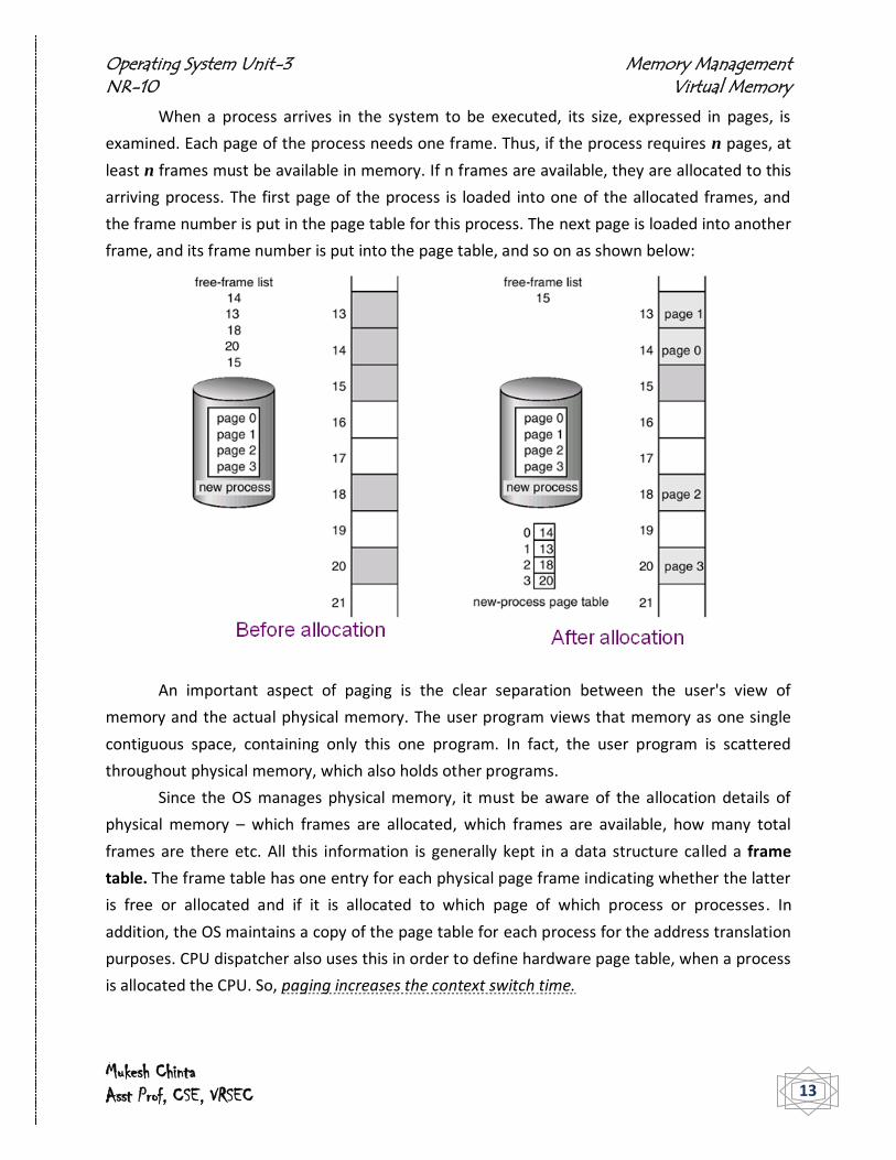
When a process arrives in the system to be executed, its size, expressed in pages, is
examined. Each page of the process needs one frame. Thus, if the process requires n pages, at
least n frames must be available in memory. If n frames are available, they are allocated to this
arriving process. The first page of the process is loaded into one of the allocated frames, and
the frame number is put in the page table for this process. The next page is loaded into another
frame, and its frame number is put into the page table, and so on as shown below:
An important aspect of paging is the clear separation between the user's view of
memory and the actual physical memory. The user program views that memory as one single
contiguous space, containing only this one program. In fact, the user program is scattered
throughout physical memory, which also holds other programs.
Since the OS manages physical memory, it must be aware of the allocation details of
physical memory – which frames are allocated, which frames are available, how many total
frames are there etc. All this information is generally kept in a data structure called a frame
table. The frame table has one entry for each physical page frame indicating whether the latter
is free or allocated and if it is allocated to which page of which process or processes. In
addition, the OS maintains a copy of the page table for each process for the address translation
purposes. CPU dispatcher also uses this in order to define hardware page table, when a process
is allocated the CPU. So, paging increases the context switch time.

Operating System Unit-3 Memory Management NR-10 Virtual Memory
Mukesh Chinta Asst Prof, CSE, VRSEC 14
Hardware Implementation
In the hardware implementation of the page table, it can be implemented as a set of dedicated
registers. The use of registers is satisfactory only if the page table is small. For contemporary
computers, where page table is very large, the use of fast registers to implement the page table
is not feasible. Hence the page table is kept in main memory and a page table base register
(PTBR) points to the page table. Changing the page tables requires changing only this one
register reducing context switch time. But the time required for accessing the user location is
too large.
The solution to this problem is to use a special small fast lookup hardware cache called
translation look aside buffer (TLB). The TLB is associative, high speed memory. Each entry in
the TLB consists of two parts – a key (or a tag) and a value. The TLB contains only a few of the
page table entries. When a logical address is generated by the CPU its page number is
presented to the TLB. If the page number is found, its frame number is immediately available
and is used to access memory. If the page number is not in the TLB (known as TLB miss), a
memory reference to the page table must be made. When the frame number is obtained, it can
be used to access memory. Some TLB’s allow entries to be wired down, that is they cannot be
removed from the TLB. TLB entries for kernel code are wired down.
Some TLB’s store address-space identifiers (ASIDS) in each TLB entry. An ASID uniquely
identifies each process and is used to provide address space protection for that process. An
ASID allows the TLB to contain entries for several different processes simultaneously. If the TLB

Operating System Unit-3 Memory Management NR-10 Virtual Memory
Mukesh Chinta Asst Prof, CSE, VRSEC 15
does not support separate ASIDs, then every time a new page table is selected, the TLB must be
flushed or erased to ensure that the next executing process does not use the wrong translation
information.
Operation of Paging with TLB
The percentage of times that a particular page number is found in the TLB is called the hit ratio.
To find the effective memory access time, each case is weighted by its probability.
Associative Lookup = time unit
Assume memory cycle time is 1 microsecond
Hit ratio – percentage of times that a page number is found in the associative registers;
ration related to number of associative registers.
Hit ratio =
Effective Access Time (EAT)
EAT = (1 + ) + (2 + )(1 – )
= 2 + –
Protection
Memory protection in a paged environment is accomplished by protection bits associated with
each frame. One additional bit is generally attached to each entry in the page table – a valid –
invalid bit. When this bit is set to valid, the associated page is in the process’s logical address
space and is thus a legal page. When the bit is set to invalid, the page is not in the process’s
logical address space. OS sets this bit for each page to allow or disallow access to the page. For

Operating System Unit-3 Memory Management NR-10 Virtual Memory
Mukesh Chinta Asst Prof, CSE, VRSEC 16
a system with a 14-bit address space (0 to 16383), we may have a program that should use only
addresses 0 to 10468 and given page size of 2 KB, the situation is shown below.
Valid (v) or invalid (i) bit in a page table.
Addresses in pages 0, 1,2,3,4, and 5 are mapped normally through the page table. Any
attempt to generate an address in pages 6 or 7, however, finds that the valid- invalid bit is set
to invalid, and the computer will trap to the operating system (invalid page reference). Because
the program extends to only address 10468, any reference beyond that address is illegal.
However, references to page 5 are classified as valid, so accesses to addresses up to 12287 are
valid. Only the addresses from 12288 to 16383 are invalid. This problem is a result of the 2 KB
page size and reflects the internal fragmentation of paging.
Some systems provide hardware in the form of a page table length register (PTLR) to
indicate the size of the page table. This value is checked against every logical address to verify
that the address is in the valid range for the process. Failure of this test causes an error trap to
the OS.
Shared Pages
Paging has got an advantage of the possibility of sharing common code, which is particularly
important in a time-sharing environment. If the code is a reentrant code (or pure code), it can
be reused as shown below. Reentrant code is non-self-modifying code, i.e. it never changes
during execution. Two or more processes can use this code at the same time.

Operating System Unit-3 Memory Management NR-10 Virtual Memory
Mukesh Chinta Asst Prof, CSE, VRSEC 17
In this example, if text editor
contains 150KB of code and
50KB of data, and page sizes
of 50KB, then 8000KB is
needed for 40 users. Using
shared pages, the space
required for 40 users would
be 150KB for code and 40
copies of 50KB data for 40
users equals to 2,150KB, a
significant reduction.
Heavily used programs such as compilers, window systems, runtime libraries, database systems
and so on can be shared. To be shared, the code must be reentrant; the OS should enforce this
property.
Structure of the Page Table
Hierarchical Paging
Most modern computer systems support a large logical address space. In such an environment,
the page table itself becomes excessively large. Hence the page table cannot be allocated
contiguously in main memory. One solution to this problem is to divide the page table into
smaller pieces. This can be accomplished in several ways. One way is to use a two level paging
algorithm in which the page table itself is also paged.
A logical address (on 32-bit machine with 4K page size) is divided into a page number consisting
of 20 bits and a page offset consisting of 12 bits. Since the page table is paged, the page
number is further divided into a 10-bit page number and a 10-bit page offset. The logical
address is as shown.

Operating System Unit-3 Memory Management NR-10 Virtual Memory
Mukesh Chinta Asst Prof, CSE, VRSEC 18
Where, p1 is an index into the outer page table and p2 is the displacement within the page of
the outer page table. The address-translation method for this architecture is shown below.
Because address translation works from the outer page table inwards, this scheme is also
known as a forward-mapped page table.
Address-translation scheme for a two-level 32-bit paging architecture
Hashed Page Tables
A common approach for handling address spaces larger than 32 bits is to use a hashed page
table with the hash value being the virtual page number. Each entry in the hash table contains a
linked list of elements that hash to the same location. Each element consists of three fields:
The virtual page number
The value of the mapped page frame
Pointer to the next element in the linked list
The algorithm works as follows: The virtual page number is compared with field1 in the first
element in the linked list. If there is a match, the corresponding page frame (field2) is used to

Operating System Unit-3 Memory Management NR-10 Virtual Memory
Mukesh Chinta Asst Prof, CSE, VRSEC 19
form the desired physical address. If there is no match, subsequent entries in the linked list are
searched for a matching virtual page number.
A variation of this scheme for 64 bit address spaces uses clustered page tables which are
similar to hashed page tables except that each entry in the hash table refers to several pages
rather than a single page. Therefore, a single page table entry can store the mappings for
multiple physical page frames. Clustered page tables are useful for sparse address spaces
where memory references are non contiguous and scattered throughout the address space.
Inverted Page Tables
Each process has an associated page table. The page table has one entry for each page that the
process is using. One of the drawbacks of this method is that each page table may consist of
millions of entries. To solve this problem, we use an inverted page table.
An inverted page table has one entry for each real page (or frame) of memory. Each entry
consists of the virtual address of the page stored in that real memory location; with information
about the process that owns that page. Thus, only one page table is in the system and it has

Operating System Unit-3 Memory Management NR-10 Virtual Memory
Mukesh Chinta Asst Prof, CSE, VRSEC 20
only entry for each page of physical memory. Inverted page table often require that an address
space identifier be stored on each entry of the page table since the table usually contains
several different address spaces mapping physical memory. Storing the address space identifier
ensures that a logical page for a particular process is mapped to the corresponding physical
page frame.
Each virtual address in the system consists of a triple
<process-id, page-number, offset>.
Each inverted page-table entry is a pair <process-id, page-number> where the process-id
assumes the role of the address-space identifier. When a memory reference occurs, part of the
virtual address, consisting of <process-id, page-number>, is presented to the memory
subsystem. The inverted page table is then searched for a match. If a match is found-say, at
entry i-then the physical address <i, offset> is generated. If no match is found, then an illegal
address access has been attempted. Although this scheme decreases the amount of memory
needed to store each page table, it increases the amount of time needed to search the table
when a page reference occurs.
Shared Pages
An advantage of paging is the possibility of sharing common code. This is important in a time
sharing environment. If the code is reentrant code (or pure code); it can be shared.

Operating System Unit-3 Memory Management NR-10 Virtual Memory
Mukesh Chinta Asst Prof, CSE, VRSEC 21
Reentrant code is non self modifying code; it never changes during execution. Thus, two or
more processes can execute the same code at the same time. Each process has its own copy of
registers and data storage to hold the data for the process’s execution. The data for different
processes will be different.
Only one copy of the editor needs to be kept in physical memory. Each user’s page table
maps onto the same physical copy of the editor, but data pages are mapped onto different
frames. Other heavily used programs such as compilers, window systems, run – time libraries,
database systems can also be shared. To be sharable, the code must be reentrant. The sharing
of memory among processes on a system is similar to the sharing of the address space of the
task by threads. Shared memory can also be described as a method of inter process
communication. Some OS’s implement shared memory using shared pages.
Systems that use inverted page tables have difficulty implementing shared memory.
Shared memory is usually implemented as multiple virtual addresses (one for each process
sharing the memory) that are mapped to one physical address. This standard method cannot be
used; however, as there is only one virtual page entry for every physical page, so one physical
page cannot have two (or more) shared virtual addresses.
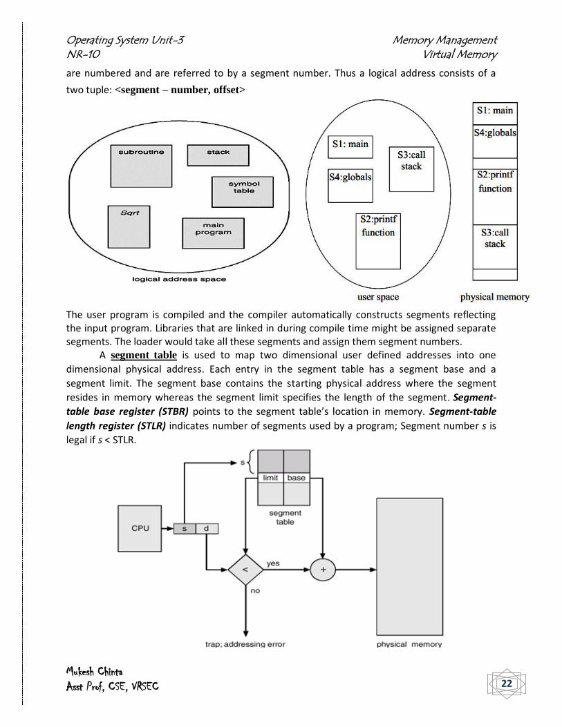
Segmentation
The user’s view of the memory is not the same as the actual physical memory. The user’s view
is mapped onto physical memory. This mapping allows differentiation between logical memory
and physical memory. Another possible memory management scheme, sort of a hybrid of
contiguous allocation and paging, is called segmentation.
Memory is allocated for a process as a collection of segments. These segments correspond to
logical units of memory in use by a process:
main program procedure, function, method object, local variables global variables common block (Fortran) stack
Segmentation is a memory management scheme that supports the user view of memory. A
logical address space is a collection of segments. Each segment has a name and a length. The
addresses specify both the segment name and the offset within the segment. The user
therefore specifies each address by two quantities – a segment name and an offset. Segments
Operating System Unit-3 Memory Management NR-10 Virtual Memory
Mukesh Chinta Asst Prof, CSE, VRSEC 22
are numbered and are referred to by a segment number. Thus a logical address consists of a
two tuple: <segment – number, offset>
The user program is compiled and the compiler automatically constructs segments reflecting the input program. Libraries that are linked in during compile time might be assigned separate segments. The loader would take all these segments and assign them segment numbers.
A segment table is used to map two dimensional user defined addresses into one
dimensional physical address. Each entry in the segment table has a segment base and a
segment limit. The segment base contains the starting physical address where the segment
resides in memory whereas the segment limit specifies the length of the segment. Segment-
table base register (STBR) points to the segment table’s location in memory. Segment-table
length register (STLR) indicates number of segments used by a program; Segment number s is
legal if s < STLR.
Operating System Unit-3 Memory Management NR-10 Virtual Memory
Mukesh Chinta Asst Prof, CSE, VRSEC 23
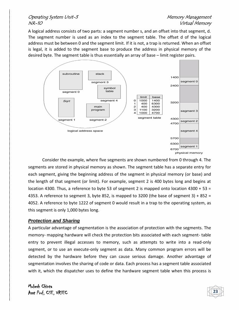
A logical address consists of two parts: a segment number s, and an offset into that segment, d.
The segment number is used as an index to the segment table. The offset d of the logical
address must be between 0 and the segment limit. If it is not, a trap is returned. When an offset
is legal, it is added to the segment base to produce the address in physical memory of the
desired byte. The segment table is thus essentially an array of base – limit register pairs.
Consider the example, where five segments are shown numbered from 0 through 4. The
segments are stored in physical memory as shown. The segment table has a separate entry for
each segment, giving the beginning address of the segment in physical memory (or base) and
the length of that segment (or limit). For example, segment 2 is 400 bytes long and begins at
location 4300. Thus, a reference to byte 53 of segment 2 is mapped onto location 4300 + 53 =
4353. A reference to segment 3, byte 852, is mapped to 3200 (the base of segment 3) + 852 =
4052. A reference to byte 1222 of segment 0 would result in a trap to the operating system, as
this segment is only 1,000 bytes long.
Protection and Sharing
A particular advantage of segmentation is the association of protection with the segments. The
memory- mapping hardware will check the protection bits associated with each segment- table
entry to prevent illegal accesses to memory, such as attempts to write into a read-only
segment, or to use an execute-only segment as data. Many common program errors will be
detected by the hardware before they can cause serious damage. Another advantage of
segmentation involves the sharing of code or data. Each process has a segment table associated
with it, which the dispatcher uses to define the hardware segment table when this process is
Operating System Unit-3 Memory Management NR-10 Virtual Memory
Mukesh Chinta Asst Prof, CSE, VRSEC 24
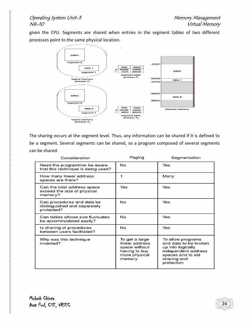
given the CPU. Segments are shared when entries in the segment tables of two different
processes point to the same physical location.
The sharing occurs at the segment level. Thus, any information can be shared if it is defined to
be a segment. Several segments can be shared, so a program composed of several segments
can be shared.

Operating System Unit-3 Memory Management NR-10 Virtual Memory
Mukesh Chinta Asst Prof, CSE, VRSEC 25
As opposed to paging, segmentation has the following advantages:
No internal fragmentation (but: external fragmentation)
May save memory if segments are very small and should not be combined into one page (e.g.
for reasons of protection)
Segment tables: only one entry per actual segment as opposed to one per page in VM
Average segment size >> average page size less overhead (smaller tables)
Also, Segmentation has the following disadvantages:
External fragmentation
Costly memory management algorithms
o Segmentation: find free memory area big enough (search!)
o Paging: keep list of free pages, any page is ok (take first!)
Segments of unequal size not suited as well for swapping
Paged Segmentation
Both paging and segmentation have advantages and disadvantages. Both are merging
memory models toward a mixture of paging and segmentation. Intel 386 architecture combines
these two methods to improve on each. The logical-address space of a process is divided into
two partitions. The first partition consists of up to 8 KB segments that are private to that
process. The second partition consists of up to 8 KB segments that are shared among all the
processes. Information about the first partition is kept in the local descriptor table (LDT),
information about the second partition is kept in the global descriptor table (GDT). Each entry
in the LDT and GDT consists of 8 bytes, with detailed information about a particular segment
including the base location and length of that segment. Paging is transparent to the
programmer. Segmentation is visible to the programmer and each segment is broken into fixed-
size pages. The logical address is a pair <selector, offset>, where the selector is a 16-bit number.
The machine has six segment registers, allowing six segments to be addressed at any one time
by a process. It has six 8-byte microprogram registers to hold the corresponding descriptors
from either the LDT or GDT. This cache lets the 386 avoid having to read the descriptor from
memory for every memory reference. The physical address on the 386 is 32 bits long and is
formed as follows. The segment register points to the appropriate entry in the LDT or GDT. The
base and limit information about the segment in question are used to generate a linear
address. First, the limit is used to check for address validity. If the address is not valid, a

Operating System Unit-3 Memory Management NR-10 Virtual Memory
Mukesh Chinta Asst Prof, CSE, VRSEC 26
memory fault is generated, resulting in a trap to the operating system. If it is valid, then the
value of the offset is added to the value of the base, resulting in a 32-bit linear address. This
address is then translated into a physical address.
The solution adopted in the 386 is to use a two-level paging scheme. The linear address is
divided into a page number consisting of 20 bits, and a page offset consisting of 12 bits. Since
we page the page table, the page number is further divided into a 10-bit page directory pointer
and a 10-bit page table pointer. The logical address is as follows:
To improve the efficiency of physical-memory use, Intel 386 page tables can be swapped to
disk.

Operating System Unit-3 Memory Management NR-10 Virtual Memory
Mukesh Chinta Asst Prof, CSE, VRSEC 27
Virtual Memory
All the memory management strategies have the same goal: to keep many processes in
memory simultaneously to allow multiprogramming. However, they tend to require the entire
process to be in memory before the process can execute. Virtual memory is a technique that
allows the execution of processes that may not be completely in memory. One major advantage
of this scheme is that programs can be larger than physical memory.
The ability to execute a program that is only partially in memory would confer many benefits:
A program would no longer be constrained by the amount of physical memory that is
available. Users would be able to write programs for an extremely large virtual-address
space, simplifying the programming task.
Because each user program could take less physical memory, more programs could be
run at the same time, with a corresponding increase in CPU utilization and throughput,
but with no increase in response time or turnaround time.
Less I/O would be needed to load or swap each user program into memory, so each user
program would run faster.
Thus, running a program that is not entirely in memory would benefit both the system and the
user. Virtual memory is the separation of user logical memory from physical memory. This
separation allows an extremely large virtual memory to be provided for programmers when
only a smaller physical memory is available.
In addition to separating logical memory from physical memory, virtual memory also
allows files and memory to be shared by several different processes through page sharing. The
sharing of pages further allows performance improvements during process creation.

Operating System Unit-3 Memory Management NR-10 Virtual Memory
Mukesh Chinta Asst Prof, CSE, VRSEC 28
Virtual memory is commonly implemented by demand paging. It can also be
implemented in a segmentation system. Several systems provide a paged segmentation
scheme, where segments are broken into pages. Thus, the user view is segmentation, but the
operating system can implement this view with demand paging. Demand segmentation can
also be used to provide virtual memory.
Demand Paging
A demand-paging system is similar to a paging system with swapping. The basic idea behind
demand paging is that when a process is swapped in, its pages are not swapped in all at once.
Rather they are swapped in only when the process needs them (on demand). This is termed a
lazy swapper, although a pager is a more accurate term. A swapper manipulates entire
processes, whereas a pager is concerned with the individual pages of a process.
Transfer of a paged memory to contiguous disk space
When a process is to be swapped in, the pager guesses which pages will be used before
the process is swapped out again. Instead of swapping in a whole process, the pager brings only
those necessary pages into memory. Thus, it avoids reading into memory pages that will not be
used anyway, decreasing the swap time and the amount of physical memory needed.
The valid-invalid bit scheme is used to distinguish between those pages that are in
memory and those pages that are on the disk. Here, when this bit is set to "valid," this value
indicates that the associated page is both legal and in memory. If the bit is set to "invalid," this
value indicates that the page either is not valid (that is, not in the logical address space of the
process), or is valid but is currently on the disk.

Operating System Unit-3 Memory Management NR-10 Virtual Memory
Mukesh Chinta Asst Prof, CSE, VRSEC 29
The page-table entry for a page that is brought into memory is set as usual, but the
page-table entry for a page that is not currently in memory is simply marked invalid, or contains
the address of the page on disk.
If the process only ever accesses pages that are loaded in memory (memory resident pages),
then the process runs exactly as if all the pages were loaded in to memory. On the other hand,
if a page is needed that was not originally loaded up, then a page fault trap is generated, i.e.
when access to made to a page marked invalid. The paging hardware, in translating the address
through the page table, will notice that the invalid bit is set, causing a trap to the operating
system. This trap is the result of the operating system's failure to bring the desired page into
memory (in an attempt to minimize disk-transfer overhead and memory requirements), rather
than an invalid address error as a result of an attempt to use an illegal memory address (such as
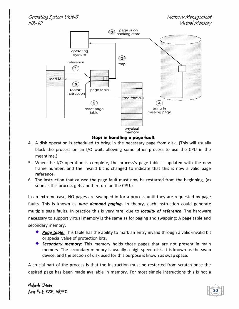
an incorrect array subscript). This trap is handled in a series of steps:
1. The memory address requested is first checked, to make sure it was a valid memory request.
2. If the reference was invalid, the process is terminated. Otherwise, the page must be paged in.
3. A free frame is located, possibly from a free-frame list.
Operating System Unit-3 Memory Management NR-10 Virtual Memory
Mukesh Chinta Asst Prof, CSE, VRSEC 30
Steps in handling a page fault
4. A disk operation is scheduled to bring in the necessary page from disk. (This will usually
block the process on an I/O wait, allowing some other process to use the CPU in the
meantime.)
5. When the I/O operation is complete, the process's page table is updated with the new frame number, and the invalid bit is changed to indicate that this is now a valid page reference.
6. The instruction that caused the page fault must now be restarted from the beginning, (as soon as this process gets another turn on the CPU.)
In an extreme case, NO pages are swapped in for a process until they are requested by page
faults. This is known as pure demand paging. In theory, each instruction could generate
multiple page faults. In practice this is very rare, due to locality of reference. The hardware
necessary to support virtual memory is the same as for paging and swapping: A page table and
secondary memory.
Page table: This table has the ability to mark an entry invalid through a valid-invalid bit or special value of protection bits.
Secondary memory: This memory holds those pages that are not present in main memory. The secondary memory is usually a high-speed disk. It is known as the swap device, and the section of disk used for this purpose is known as swap space.
A crucial part of the process is that the instruction must be restarted from scratch once the
desired page has been made available in memory. For most simple instructions this is not a

Operating System Unit-3 Memory Management NR-10 Virtual Memory
Mukesh Chinta Asst Prof, CSE, VRSEC 31
major difficulty. However there are some architectures that allow a single instruction to modify
a fairly large block of data, (which may span a page boundary ), and if some of the data gets
modified before the page fault occurs, this could cause problems. One solution is to access both
ends of the block before executing the instruction, guaranteeing that the necessary pages get
paged in before the instruction begins.
Performance of Demand Paging
Demand paging can have a significant effect on the performance of a computer system. As long
as we have no page faults, the effective access time is equal to the memory access time. If,
however, a page fault occurs, we must first read the relevant page from disk, and then access
the desired word. Let p be the probability of a page fault (0 ≤ p ≤ 1). We would expect p to be
close to zero; that is, there will be only a few page faults. The effective access time is then
effective access time = (1 - p) x ma + p x page fault time.
For Example:
– Memory access time = 200 nanoseconds
– Average page-fault service time = 8 milliseconds
– Suppose p = Probability of miss, 1-p = Probably of hit
– Then, we can compute EAT as follows:
EAT = (1 – p) x 200ns + p x 8 ms
= (1 – p) x 200ns + p x 8,000,000ns
= 200ns + p x 7,999,800ns
• If one access out of 1,000 causes a page fault, then EAT = 8.2 μs, which is slowdown
by a factor of 40!
It is important to keep the page-fault rate low in a demand-paging system. Otherwise, the
effective access time increases, slowing process execution dramatically.
Page Replacement
In order to make the most use of virtual memory, several processes are loaded into memory at
the same time. Since, only the pages that are actually needed by each process at any given time
are loaded, there is room to load many more processes than loading the entire process.
However memory is also needed for other purposes (such as I/O buffering), and problem arises
when some process suddenly decides it needs more pages and there aren't any free frames
available.
One of the most common solutions called page replacement is to find some page in
memory that isn't being used right now, and swap that page only out to disk, freeing up a frame
that can be allocated to the process requesting it.

Operating System Unit-3 Memory Management NR-10 Virtual Memory
Mukesh Chinta Asst Prof, CSE, VRSEC 32
Basic Page Replacement
The page-fault handling must be modified to free up a frame if necessary, as follows:
Find the location of the desired page on the disk, either in swap space or in the file system.
Find a free frame: o If there is a free frame, use it. o If there is no free frame, use a page-replacement algorithm to select an existing
frame to be replaced, known as the victim frame. o Write the victim frame to disk. Change all related page tables to indicate that
this page is no longer in memory. Read in the desired page and store it in the frame. Adjust all related page and frame
tables to indicate the change. Restart the process that was waiting for this page
If no frames are free, two page transfers are required, which effectively doubles the page-fault
service time increasing the effective access time. This can be alleviated somewhat by assigning
a modify bit, or dirty bit to each page, indicating whether or not it has been changed since it
was last loaded in from disk. If the dirty bit has not been set, then the page is unchanged, and
does not need to be written out to disk. Otherwise the page write is required. It should come as
no surprise that many page replacement strategies specifically look for pages that do not have
Operating System Unit-3 Memory Management NR-10 Virtual Memory
Mukesh Chinta Asst Prof, CSE, VRSEC 33
their dirty bit set, and preferentially select clean pages as victim pages. It should also be
obvious that unmodifiable code pages never get their dirty bits set.
Page replacement is basic to demand paging and two main requirements are to be
implemented for a successful demand paging system. A frame-allocation algorithm and a
page-replacement algorithm are to be developed, where the former centers around how many
frames are allocated to each process ( and to other needs ), and the latter deals with how to
select a page for replacement when there are no free frames available. The overall goal in
selecting and tuning these algorithms is to generate the fewest number of overall page faults
and there are many different algorithms present. Algorithms are evaluated using a given string
of memory accesses known as a reference string, where the algorithms are run on this
particular string of memory references and computing the number of page faults. Also the
number of page frames available is to be known to determine the number of page faults for a
particular reference string and a page-replacement algorithm.
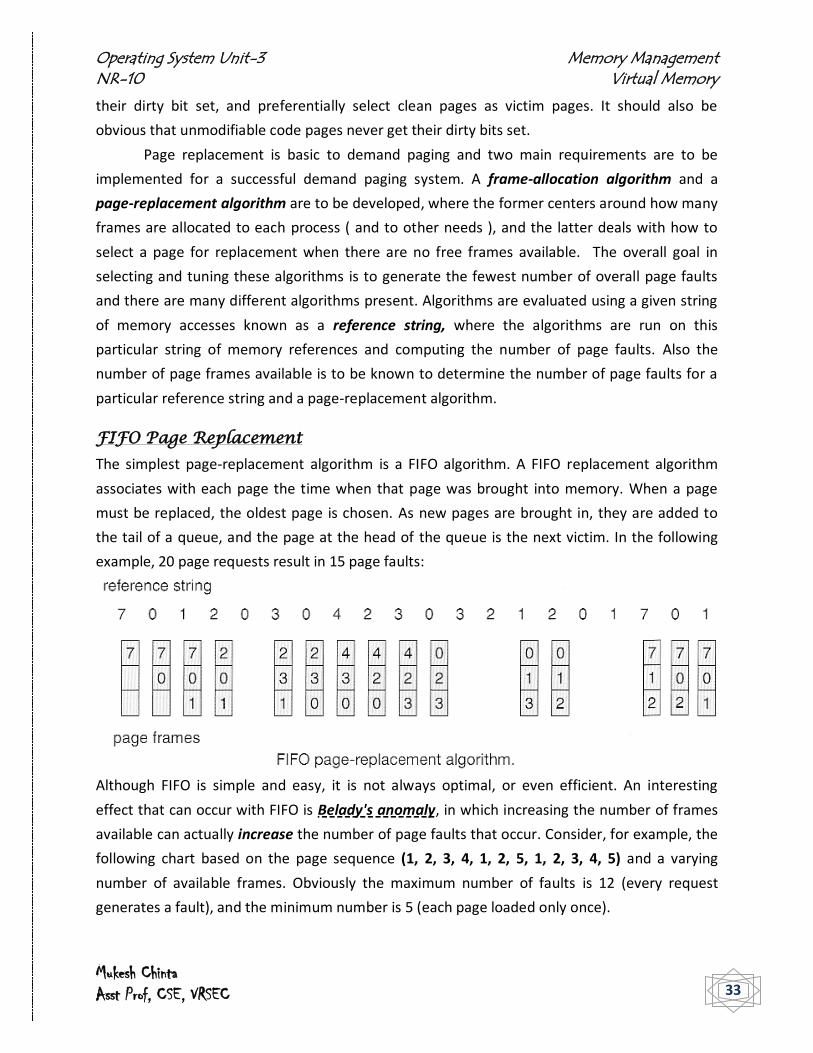
FIFO Page Replacement
The simplest page-replacement algorithm is a FIFO algorithm. A FIFO replacement algorithm
associates with each page the time when that page was brought into memory. When a page
must be replaced, the oldest page is chosen. As new pages are brought in, they are added to
the tail of a queue, and the page at the head of the queue is the next victim. In the following
example, 20 page requests result in 15 page faults:
Although FIFO is simple and easy, it is not always optimal, or even efficient. An interesting
effect that can occur with FIFO is Belady's anomaly, in which increasing the number of frames
available can actually increase the number of page faults that occur. Consider, for example, the
following chart based on the page sequence (1, 2, 3, 4, 1, 2, 5, 1, 2, 3, 4, 5) and a varying
number of available frames. Obviously the maximum number of faults is 12 (every request
generates a fault), and the minimum number is 5 (each page loaded only once).

Operating System Unit-3 Memory Management NR-10 Virtual Memory
Mukesh Chinta Asst Prof, CSE, VRSEC 34
The figure shows the curve of page
faults versus the number of available
frames. We notice that the number of
faults for four frames (10) is greater
than the number of faults for three
frames (nine)! This most unexpected
result is known as Belady's anomaly.
For some page-replacement algorithms,
the page fault rate may increase as the
number of allocated frames increases
Optimal Page Replacement
The discovery of Belady's anomaly lead to the search for an optimal page-replacement
algorithm, which is simply that which yields the lowest of all possible page-faults, and which
does not suffer from Belady's anomaly. Such an algorithm does exist, and is called OPT or MIN.
This algorithm is simply "Replace the page that will not be used for the longest time in the
future."
The following figure shows that by applying OPT to the same reference string used for
the FIFO example; the minimum number of possible page faults is 9. Since 6 of the page-faults
are unavoidable (the first reference to each new page), FIFO can be shown to require 3 times as
many (extra) page faults as the optimal algorithm
Unfortunately OPT cannot be implemented in practice because it requires future knowledge of
the reference string. As a result, the optimal algorithm is used mainly for comparison studies.
Operating System Unit-3 Memory Management NR-10 Virtual Memory
Mukesh Chinta Asst Prof, CSE, VRSEC 35
LRU Page Replacement
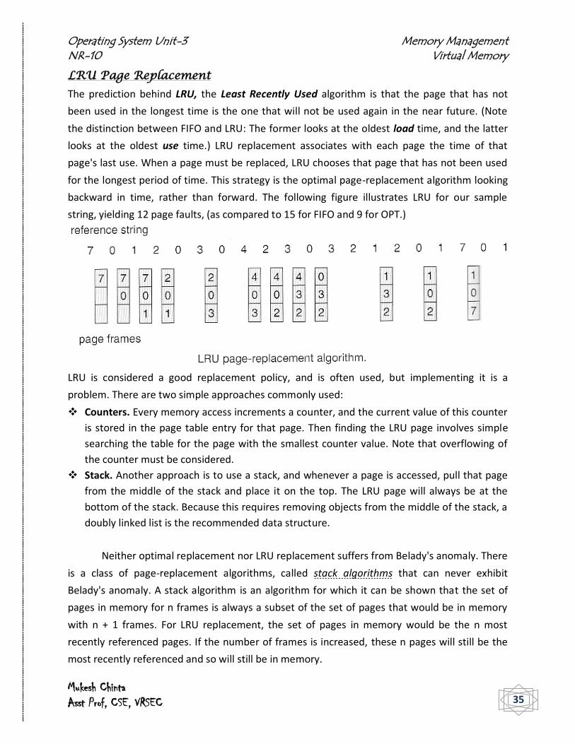
The prediction behind LRU, the Least Recently Used algorithm is that the page that has not
been used in the longest time is the one that will not be used again in the near future. (Note
the distinction between FIFO and LRU: The former looks at the oldest load time, and the latter
looks at the oldest use time.) LRU replacement associates with each page the time of that
page's last use. When a page must be replaced, LRU chooses that page that has not been used
for the longest period of time. This strategy is the optimal page-replacement algorithm looking
backward in time, rather than forward. The following figure illustrates LRU for our sample
string, yielding 12 page faults, (as compared to 15 for FIFO and 9 for OPT.)
LRU is considered a good replacement policy, and is often used, but implementing it is a
problem. There are two simple approaches commonly used:
Counters. Every memory access increments a counter, and the current value of this counter
is stored in the page table entry for that page. Then finding the LRU page involves simple
searching the table for the page with the smallest counter value. Note that overflowing of
the counter must be considered.
Stack. Another approach is to use a stack, and whenever a page is accessed, pull that page
from the middle of the stack and place it on the top. The LRU page will always be at the
bottom of the stack. Because this requires removing objects from the middle of the stack, a
doubly linked list is the recommended data structure.
Neither optimal replacement nor LRU replacement suffers from Belady's anomaly. There
is a class of page-replacement algorithms, called stack algorithms that can never exhibit
Belady's anomaly. A stack algorithm is an algorithm for which it can be shown that the set of
pages in memory for n frames is always a subset of the set of pages that would be in memory
with n + 1 frames. For LRU replacement, the set of pages in memory would be the n most
recently referenced pages. If the number of frames is increased, these n pages will still be the
most recently referenced and so will still be in memory.

Operating System Unit-3 Memory Management NR-10 Virtual Memory
Mukesh Chinta Asst Prof, CSE, VRSEC 36
LRU-Approximation Page Replacement
Unfortunately full implementation of LRU requires hardware support, and few systems provide
the full hardware support necessary. However many systems offer some degree of HW support,
enough to approximate LRU fairly well. (In the absence of ANY hardware support, FIFO might be
the best available choice.)
In particular, many systems provide a reference bit for every entry in a page table,
which is set anytime that page is accessed. Initially all bits are set to zero, and they can also all
be cleared at any time. The pages that have been used can be easily determined by examining
the reference bits, though the order might not be known.
Additional-Reference-Bits Algorithm
Finer grain is possible by storing the most recent 8 reference bits for each page in an 8-bit byte
in the page table entry, which is interpreted as an unsigned int. At periodic intervals (clock
interrupts), the OS takes control, and right-shifts each of the reference bytes by one bit. The
operating system shifts the reference bit for each page into the high-order bit of its 8-bit byte,
shifting the other bits right 1 bit, discarding the low-order bit. These &bit shift registers contain
the history of page use for the last eight time periods. If the shift register contains 00000000,
then the page has not been used for eight time periods; a page that is used at least once each
period would have a shift register value of 11111111. A page with a history register value of
11000100 has been used more recently than has one with 01110111. At any given time, the
page with the smallest value for the reference byte is the LRU page. Obviously the specific
number of bits used and the frequency with which the reference byte is updated are
adjustable, and are tuned to give the fastest performance on a given hardware platform.

Operating System Unit-3 Memory Management NR-10 Virtual Memory
Mukesh Chinta Asst Prof, CSE, VRSEC 37
Second-Chance Algorithm
The second chance algorithm is essentially a FIFO, except the reference bit is used to give pages
a second chance at staying in the page table. When a page must be replaced, the page table is
scanned in a FIFO (circular queue) manner. If a page is found with its reference bit not set, then
that page is selected as the next victim. If, however, the next page in the FIFO does have its
reference bit set, then it is given a second chance. The reference bit is cleared, and the FIFO
search continues.
One way to implement the second-chance (sometimes referred to as the clock)
algorithm is as a circular queue. A pointer indicates which page is to be replaced next. When a
frame is needed, the pointer advances until it finds a page with a 0 reference bit. As it
advances, it clears the reference bits. Once a victim page is found, the page is replaced, and the
new page is inserted in the circular queue in that position.
In the worst case, when all bits are set, the pointer cycles through the whole queue,
giving each page a second chance. It clears all the reference bits before selecting the next page
for replacement. Second-chance replacement degenerates to FIFO replacement if all bits are
set. This algorithm is also known as the clock algorithm, from the hands of the clock moving
around the circular queue.

Operating System Unit-3 Memory Management NR-10 Virtual Memory
Mukesh Chinta Asst Prof, CSE, VRSEC 38
Enhanced Second-Chance Algorithm
The enhanced second chance algorithm looks at the reference bit and the modify bit ( dirty
bit ) as an ordered page, and classifies pages into one of four classes:
1. ( 0, 0 ) - Neither recently used nor modified. 2. ( 0, 1 ) - Not recently used, but modified. 3. ( 1, 0 ) - Recently used, but clean. 4. ( 1, 1 ) - Recently used and modified.
This algorithm searches the page table in a circular fashion (in as many as four passes), looking
for the first page it can find in the lowest numbered category. I.e. it first makes a pass looking
for a ( 0, 0 ), and then if it can't find one, it makes another pass looking for a ( 0, 1 ), etc. The
main difference between this algorithm and the previous one is that here preference is given to
pages that have been modified to reduce the number of I/O required.
Counting-Based Page Replacement
There are several algorithms based on counting the number of references that have been made to a given page, such as:
o Least Frequently Used, LFU: Replace the page with the lowest reference count. A
problem can occur if a page is used frequently initially and then not used any more,
as the reference count remains high. A solution to this problem is to right-shift the
counters periodically, yielding a time-decaying average reference count.
o Most Frequently Used, MFU: Replace the page with the highest reference count.
The logic behind this idea is that pages that have already been referenced a lot have
been in the system a long time, and we are probably done with them, whereas
pages referenced only a few times have only recently been loaded, and we still need
them.
In general counting-based algorithms are not commonly used, as their implementation is expensive and they do not approximate OPT well.
Page buffering Algorithms
There are a number of page-buffering algorithms that can be used in conjunction with the
afore-mentioned algorithms, to improve overall performance and sometimes make up for
inherent weaknesses in the hardware and/or the underlying page-replacement algorithms:
Maintain a certain minimum number of free frames at all times. When a page-fault
occurs, go ahead and allocate one of the free frames from the free list first, to get the
requesting process up and running again as quickly as possible, and then select a victim
page to write to disk and free up a frame as a second step.

Operating System Unit-3 Memory Management NR-10 Virtual Memory
Mukesh Chinta Asst Prof, CSE, VRSEC 39
Keep a list of modified pages, and when the I/O system is otherwise idle, have it write
these pages out to disk, and then clear the modify bits, thereby increasing the chance of
finding a "clean" page for the next potential victim.
Keep a pool of free frames, but remember what page was in it before it was made free.
Since the data in the page is not actually cleared out when the page is freed, it can be
made an active page again without having to load in any new data from disk. This is
useful when an algorithm mistakenly replaces a page that in fact is needed again soon.
Allocation of Frames
The two important tasks in virtual memory management are page-replacement strategy and a
frame-allocation strategy.
Minimum Number of Frames
The absolute minimum number of frames that a process must be allocated is dependent
on system architecture, and corresponds to the worst-case scenario of the number of
pages that could be touched by a single (machine) instruction.
If an instruction (and its operands) spans a page boundary, then multiple pages could be
needed just for the instruction fetch.
Memory references in an instruction touch more pages, and if those memory locations
can span page boundaries, then multiple pages could be needed for operand access
also.
Allocation Algorithms
Equal Allocation - If there are m frames available and n processes to share them, each
process gets m / n frames, and the leftovers are kept in a free-frame buffer pool.
Proportional Allocation - Allocate the frames proportionally to the size of the process,
relative to the total size of all processes. So if the size of process i is S_i, and S is the sum
of all S_i, then the allocation for process P_i is a_i = m * S_i / S.
Variations on proportional allocation could consider priority of process rather than just
their size.
Global versus Local Allocation
With multiple processes competing for frames, page-replacement algorithms can be classified
into two broad categories: global replacement and local replacement. With local replacement,
the number of pages allocated to a process is fixed, and page replacement occurs only amongst
the pages allocated to this process. With global replacement, any page may be a potential
victim, whether it currently belongs to the process seeking a free frame or not. Local page
replacement allows processes to better control their own page fault rates, and leads to more

Operating System Unit-3 Memory Management NR-10 Virtual Memory
Mukesh Chinta Asst Prof, CSE, VRSEC 40
consistent performance of a given process over different system load levels. Global page
replacement is overall more efficient, and is the more commonly used approach.
Thrashing
If a process cannot maintain its minimum required number of frames, then it must be swapped
out, freeing up frames for other processes. This is an intermediate level of CPU scheduling. But
if a process can keep its minimum, but cannot keep all of the frames it is currently using on a
regular basis, it is forced to page out pages that it will need again in the very near future,
leading to large numbers of page faults. A process that is spending more time paging than
executing is said to be thrashing.
Cause of Thrashing
Early process scheduling schemes would control the level of multiprogramming allowed
based on CPU utilization, adding in more processes when CPU utilization was low.
The problem is that when memory filled up and processes started spending lots of time
waiting for their pages to page in, then CPU utilization would lower, causing the
schedule to add in even more processes and exacerbating the problem. Eventually the
system would essentially grind to a halt.
Local page replacement policies can prevent one thrashing process from taking pages
away from other processes, but it still tends to clog up the I/O queue, thereby slowing
down any other process that needs to do even a little bit of paging.
The locality model notes that processes typically access memory references in a given locality,
making lots of references to the same general area of memory before moving periodically to a
new locality. If we could just keep as many frames as are involved in the current locality, then
page faulting would occur primarily on switches from one locality to another.
Working-Set Model
The working set model is based on the concept of locality, and defines a working set window,
of length delta. Whatever pages are included in the most recent delta page references are said
to be in the processes working set window, and comprise its current working set, as shown.

Operating System Unit-3 Memory Management NR-10 Virtual Memory
Mukesh Chinta Asst Prof, CSE, VRSEC 41
Page-Fault Frequency
A more direct approach is to recognize that what we really want to control is the page-fault
rate, and to allocate frames based on this directly measurable value. If the page-fault rate
exceeds a certain upper bound then that process needs more frames, and if it is below a given
lower bound, then it can afford to give up some of its frames to other processes.
Other Considerations
Prepaging
The basic idea behind prepaging is to predict the pages that will be needed in the near future,
and page them in before they are actually requested. If a process was swapped out and we
know what its working set was at the time, then when we swap it back in we can go ahead and
page back in the entire working set, before the page faults actually occur. With small ( data )
files we can go ahead and prepage all of the pages at one time. Prepaging can be of benefit if
the prediction is good and the pages are needed eventually, but slows the system down if the
prediction is wrong.
Page Size
There are quite a few trade-offs of small versus large page sizes. Small pages waste less
memory due to internal fragmentation. Large pages require smaller page tables. For disk
access, the latency and seek times greatly outweigh the actual data transfer times. This makes
it much faster to transfer one large page of data than two or more smaller pages containing the
same amount of data. Smaller pages match locality better, because we are not bringing in data
that is not really needed. Small pages generate more page faults, with attending overhead. The

Operating System Unit-3 Memory Management NR-10 Virtual Memory
Mukesh Chinta Asst Prof, CSE, VRSEC 42
physical hardware may also play a part in determining page size. It is hard to determine an
"optimal" page size for any given system. Current norms range from 4K to 4M, and tend
towards larger page sizes as time passes.
TLB Reach
TLB Reach is defined as the amount of memory that can be reached by the pages listed in the
TLB. Increasing the size of the TLB is an obvious way of increasing TLB reach, but TLB memory is
very expensive and also draws lots of power. Increasing page sizes increases TLB reach, but also
leads to increased fragmentation loss. Some systems provide multiple size pages to increase
TLB reach while keeping fragmentation low. Multiple page sizes requires that the TLB be
managed by software, not hardware.
Inverted Page Tables
Inverted page tables store one entry for each frame instead of one entry for each virtual page.
This reduces the memory requirement for the page table, but loses the information needed to
implement virtual memory paging. A solution is to keep a separate page table for each process,
for virtual memory management purposes. These are kept on disk, and only paged in when a
page fault occurs.
I/O Interlock
There are several occasions when it may be desirable to lock pages in memory, and not let
them get paged out. Certain kernel operations cannot tolerate having their pages swapped out.
If an I/O controller is doing direct-memory access, it would be wrong to change pages in the
middle of the I/O operation. In a priority based scheduling system, low priority jobs may need
to wait quite a while before getting their turn on the CPU, and there is a danger of their pages
being paged out before they get a chance to use them even once after paging them in. In this
situation pages may be locked when they are paged in, until the process that requested them
gets at least one turn in the CPU.