operating manual - wagner werkzeugsysteme müller gmbh · 2 operating manual thread cutting ......
TRANSCRIPT

Operating ManualThread Cutting Heads Z39-2
Z39-K

2 Operating Manual Thread Cutting Heads Z39
Table of Contents
1. Preface 3
2. Security advice 5
3. Range of application 63.1. Cutting parallel external threads 63.2. Cutting taper external threads 63.2.1. Taper threads within chaser width 63.2.2. Continuous cutting of longer taper threads 63.3. Cutting left-hand threads 63.4. Skin turning bolts 6
4. Method of operation of the thread cutting head 74.1. Interaction of the individual parts of the thread cutting head 74.2. Description and coding of the chaser holders 84.3. Changing the chaser holders 84.4. Changing the chasers 9
5. The chasers 115.1. Chaser forms 115.2. Coding of the chasers 125.3. Chaser grades 135.4. Operation with or without guide teeth 135.5. Grinding the chasers 13
6. Thread Cutting 146.1. Setting the thread diameter 146.2. Faulty threads and their causes 146.3. Cooling 16
7. Tables & associated descriptions 177.1. Instructions for the use of the setting tables 177.2. Instructions for using the table of chaser holders 187.3. Setting tables Z39 197.4. Holder tables Z39 247.5. Holder table Z39-K 257.6. Special holder table Z 39 26
8. Angles 278.1. Selecting the top rake 278.2. Calculating the cutting speed 298.3. Calculating the helix angle 31
9. Illustrated parts list and accessories 339.1. Individual parts of thread cutting head Z 39 33
10. Special detent 36

Operating Manual Thread Cutting Heads Z39 3
Preface
1. Preface
Dear customer,you purchased a high-quality technical tool which guarantees you an efficient work performance.The cutting heads of our company are widely known for their high quality and long-life cycle. We do hope that you are perfectly satisfied with our products, too.
Customer care even after purchase:This operating manual helps you to make the first steps with the new WAGNER® pro-duct. It helps to understand its Function and alludes to possible hazards.
However, should you be in need of further consulting service, training or some other advice do not hesitate to contact us.Even if you are not happy with one of our WAGNER® products!Our marketing staff is more than glad to help you at anytime.
This operating manual should be read, understood and paid attention to by every person in charge.In particularly this applies for safety- and hazard warnings which are specially indi-cated. (See chapter 2. Security Advice)Following these advices helps to avoid accidents and faults.
This manual provides all information on operation and maintenance of your WAG-NER® Thread cutting head. The information laid down in this manual is state of the art according to the production date of the product.
Please use only this manual when working with the thread cutting head. The WAG-NER® Werkzeugsysteme Müller GmbH reserves the right to technical amendments re-garding the improvement of this product. However, the WAGNER® Werkzeugsyteme Müller GmbH cannot held liable for any faults, damages, failures and production loss resulting thereof caused by disregarding of some aspects mentioned in this manual.
Due to copyright reasons we would like to point out that this operating manual is for internal use only. Please refrain from distributing it to third parties.In addition to the instructions mentioned before, national and international „safety in-structions and rules for accident prevention“ apply when operating and maintaining the cutting head. The operating manual, in particular, the „safety instructions“ have to be read carefully. Through observing the safety instructions and legal regulations damage to persons, mechanical breakdown and damage to the cutting head should be avoided.
WarrantyWe warrant perfect function of the thread cutting heads when purchasing and using original WAGNER® spare parts and equipment.We cannot hold liable for any damage to persons, mechanical breakdown and da-mage to the thread cutting head in the event of: • Improper installation and operation• Usage of non original spare parts• Removal of component parts and screws• Unauthorised modifications of our products • Usage of damaged cutting heads.
Please note: Read this operating manual carefully be-fore initial operation and take note of the hazard warnings!

4 Operating Manual Thread Cutting Heads Z39
Preface
We cannot hold liable for any use of components which are not manufactured or not approved by WAGNER®.We cannot hold liable for damages occurring through removing of safety devices of the machine. We imply the placing into operation of our products on efficient tech-nical machines.
Normal use:Don’t use force when mounting, dismounting and operating the cutting head. Other-wise you will cause damages to the cutting head or the machine.
Initial operationCheck the function of the thread cutting head before initial operation.
Limitation of liability: Please note: Use this pro-
duct only for the purpose it is manufactured for!
Please take notice of the sa-fety instructions and hazard
warnings! The thread cutting head should only be used by trained technical staff.
Otherwise health hazard or danger of life and damage to property cannot be ruled out. In that case we cannot hold liable for any of these
damages.

Operating Manual Thread Cutting Heads Z39 5
Security advice
2. Security advice
• Persons operating, maintaining or servicing the cutting head should always read and understand the operating manual in particular the safety inst-ructions. Persons under the influence of alcohol and /or drugs may cause accidents!
• Take into account the weight of the thread cutting head upon installation. If necessary lift it with a lifting gear.
• Please take note that the cutting sites between tool and machine are kept clean. Should they be fouled the accuracy of the workpiece is affected.
• When installing the tools switch off the machine at the line switch. When changing the chaser holders and chasers take note that the tool shaft isn’t starting unexpectedly.
• Remove all tools and testing equipment from the workspace of the machine before activating it. Risk of injury arises through tools and testing equip-ment which are flung about!
• Close guard door or protection case before machining. Flying chipping and damaged tools or workpieces can cause damage to persons or mechanical breakdown.
• Make sure that the thread cutting head isn’t loosening when machining.
• Don’t touch the cutting head upon closing. Don’t touch rotating tools: Risk of injury!
• Be very careful when dealing with the chasers. The edges of the chasers are very sharp. Wear safety gloves if necessary!
• Please ensure that the thread cutting head is properly secured and attached whilst transporting.

6 Operating Manual Thread Cutting Heads Z39
Range of application
3. Range of application
3.1. Cutting parallel external threads
All external threads listed in the table of chaser holders can be cut. Acme threads or other deep threads may be cut in two or more passes.
3.2. Cutting taper external threads
There are two methods that can be used:
3.2.1. Taper threads within chaser width
This method can only be used if the length of thread, including the throat of the chaser, is smaller than the width of the chaser. The taper ratio should not exceed 1:16. At the end of the cut, the chaser head is opened when all 4 chasers will be retracted from the thread, leaving a slight mark. This method of operation can be carried out with the normal head and chaser holders. It is merely necessary to use the appropriate chasers for the desired taper thread.
3.2.2. Continuous cutting of longer taper threads
A tapered die ring, together with the corresponding holders and tapered sliding pads, can be supplied instead of the cylindrical cam ring. The carrier ring is pressed to the rear and the head is opened in accordance with the desired taper angle by means of a stop operated from the slide.Depending on the taper angle required, a number of different cam rings and sliding pads will be necessary. A braking mechanism is also required to prevent unwanted reversal of the carrier ring.
3.3. Cutting left-hand threads
Left-hand threads can be produced without difficulty with the same chaser dead by rotating the main spindle in the anti-clockwise directions However, left-hand holders and left-hand chasers will be required.
3.4. Skin turning bolts
We can supply skin turning tools whose external design is similar to that of the chaser jaws,exceptfortheabsenceofthreadprofiles.Theguideteetharereplacedbyаwear surface which prevents the cutting edge from digging into the workpiece.Tools of this type can be used to size bolts at low cutting speeds. If higher cutting speeds and greater outputs are desired, the use of a WAGNER® skin turning machine will be recommended. The tungsten carbide tools of such machines result in greatly reduced operating periods.

Operating Manual Thread Cutting Heads Z39 7
Method of operation of the thread cutting head
4. Method of operation of the thread cutting head
4.1. Interaction of the individual parts of the thread cutting head
1. The head bodyThe die head [1] is attached to the main spindle of the thread cutting machine by means of 4 screws [5]. The flanged bush [7] and the nut [6] should on no account be removed from the head, except for major repairs. The small spring-loaded cylinders [12] and their spings [13] press the holders outwards. The amount of travel of these cylinders is limited by the threaded studs [11]. Axial movement of the die ring; as permitted by the recesses in the guide ring, is limited by the stop pin [9] with its spring [10] and its cheese head screw [8].
2. The die ringThe cam ring [2] and the guide ring [4] are held together by means of the key plate [3] and the socket head screw [16]. These components form a complete unit, the die ring. Insertion of the taper key [27] into the hole [p] enables the cam ring [2] to be moved in relation to the guide ring [4] if the socket head screw [16] is released.The die ring can be moved on the die head to the extent permitted by the stop pin [9]. The guide ring is shown in Fig. 1 rotated through 180° in relation to all other parts of the head, to show the recess in which the stop pin [9] engages.
3. The holdersThe holders, carrying the chaser jaws, are held axially by means of the flanged bush [7]. The holders cannot be removed from the head while the stop pin [9] is enga-ged in the recess of the guide ring. Insertion of the taper key [27] through hole [a] and depressing of the stop pin [9] enables the die ring to be pushed backwards far enough to enable the holders to swing outwards. If it is desired to withdraw the die ring forward, the key should be inserted in the same way through hole [b] at the rear and pressure should be applied to the stop pin.
4. The carrier ringThis unit effects axial displacement of the die ring. The carrier jaws [31] are mounted on the dowels [32] and engage in the circular groove of the guide ring. With the aid of the carrier ring it is therefore possible to move the guide ring forward to close the head and backwards to open the head.

8 Operating Manual Thread Cutting Heads Z39
Method of operation of the thread cutting head
4.2. Description and coding of the chaser holders
The holders can only be used in sets and are not interchangeable within the various sets. The code number is engraved at [d] at the rear of the holder; for example:A 6 (capital or small letters and figures between 1 and 100).
The four holders of one set are identical. The code number such as Z39/2D will be found at [e]. The application range of the chaser holders can be obtained from the holder tables. In addition, the front of one holder at [e] carries markings indicating the cutting range for metric and Whitworth threads in addition to the code number of the holder, for example: M7-14.The holder angle is engraved below this inscription.
4.3. Changing the chaser holders
The head must be opened to enable the chaser holders to be changed. The stop collar located on the actuating rod behind the carrier ring [30] should then be re-leased to enable the carrier ring [30] to be pushed back still further. However, this is prevented by the stop pin [9] which engages in a recess of the guide ring [4]. (Fig. 1 shows the guide ring [4] displaced through 180° in relation to the die head core [1] to show this recess). The die ring can be moved backwards by inserting the taper key [27] through the hole [a] thus depressing the the stop pin [9]. This releases the chaser holders [18] from the cam ring [2]; they can therefore be swung away from the flanged bush [7] and removed by withdrawing them in the forward direction. If the chasers are changed, special care should be taken to ensure that the head and the holder are thoroughly cleaned before the holders are replaced, to prevent swarf or scale from sticking to the sliding surfaces. At the same time the spring-loaded cylinders [12] in the die head should be checked for ease of movement. The chasers [19] are marked with the numbers 1 - 4 engraved at point [m]. It is essential to ensure that for right-hand threads the chaser holders with the chasers are inserted in the clockwise direction in the correct sequence 1, 2, 3, 4. For left-hand threads the sequence 1, 2, 3, 4 applies in the anti-clockwise direction.
Fig. 1: Dismantled thread cutting head with accessories

Operating Manual Thread Cutting Heads Z39 9
Method of operation of the thread cutting head
The four chaser holders are held together by means of the clamping ring [29]; the carrier ring may next be moved forward to enable the cam ring [2] to be pushed over the sliding pads [23], so that the stop pin [9] engages in the recess.The rear setting collar should then be locked in the original position on the actuating rod. In this condition there are only two positions for the chaser head, in one of which (in the extreme forward position of the carrier ring) the head will be closed. The set-ting of the head may be considered correct if the cam ring covers the cylindrical part of the slides [23] by approximately 3 mm (1/8 inch). The head is opened by retracting the carrier ring as far as possible.The sloping section of the slides [23] will then rest against the cam ring. Movement to the rear is limited by the stop pin [9].
4.4. Changing the chasers
1. Removing the chaser from the holderTo remove the chaser [19] from the holder [18] the two clamping screws [20] must be released. The chaser [19] can then be withdrawn from the holder [18] in the direc-tion of the cutting edge. Clamping of the holders is effected most conveniently in the setting device. This should be clamped in a vice or in the vice of the machine slide. The T-headed screw [E2] should be released, the holder inserted into the bore of the setting bracket [E1] and swung against the stop [E3]. The holder is then clamped in postion by turning the T-headed screw [E2]. The clamping screws [20] can then be released by means of the Allen key (hexagonal socket wrench) [26]. 2. Setting the dial indicatorThe setting value and the required setting gauge [E5] for the desired thread should be obtained from the setting table, on which the diameters of the setting gauge are engraved. The appropriate gauge should then be inserted into the bore of the setting bracket [E1] and locked by means of the clamping screw [E2]. Care should be taken to ensure that the setting gauge [E5] is vertically adjusted in such a way that the stylus of the dial indicator rests on the correct step of the setting gauge. The dial indicator [E6] may then be adjusted in the following manner: the dial indicator is first inserted into the setting bracket [E1] and axially adjusted until the small pointer [k] of the dial indicator [E6] is accurately set to zero. The clamping screw [E4] should be tightened but not to such an extent as to interfere with the free movement of the stylus. The dial of the indicator should next be adjusted until the lame pointer [g] is also set to zero;
Fig. 2 Setting device with dial gauge

10 Operating Manual Thread Cutting Heads Z39
Method of operation of the thread cutting head
the setting gauge may then be removed and the setting device is ready for adjustment of the chaser jaws.
3. Setting the chaser in the holderIn place of the setting gauge [E5], the carefully cleaned holder [18] is now inserted into the setting bracket [E1]. The clamping plate [21], the clamping screws [20] and the adjusting screw [24] should already have been released. For larger chasers ha-ving a cross-section of 25x12 mm (0.98x0.47 in.) and larger, the adjusting screw [24] is supplemented by means of a stop whose shaft is inserted into the bore of the screw. The chaser [19] should then be inserted into the holder.
The holder is swung against the stop [E3] while the measuring pin of the dial indicator is retracted. The vertical position of the chaser holder and the chaser will be correct if the stylus of the dial gauge rests against the point of the last cutting tooth or moves closely along the side surface of the guide teeth.
The chaser must of course never be clamped in a position high enough to cause the stylus to touch the guide teeth. The holder should be clamped by means of the T-headed screw [E2], and the clamping screws [20] should be lightly tightened.The chaser may then be adjusted by means of the setting screw [24] until the dial indicator shows the value quoted for the setting in the tables. (For theoretical setting values, setting above or below centre, see explanations to the setting table see Fig. 6, page 17).
It is essential to ensure that both the small pointer [k] indicating millimetres, and the large pointer [g] indicating hundredths of one millimetre, correspond to the approp-riate setting value.
For example, if it is desired to set a value of “2.75”, the small hand must be positi-oned between “2” and “3” and the large hand on “75”. The clamping screws [20] may then be tightened, the front clamping screw being tightened first to prevent dis-tortion. It is recommended that the setting screw [24] should subsequently be firmly tightened. If the chaser is worn to such an extent that the clamping plate [21] is in danger of being distorted when the clamping screws [20] are tightened, the packing piece [34] must be inserted. This packing piece has the profile of the chaser dovetail and can be supplied in various lengths. The position in which this packing should be inserted is indicated by the number [34] in Fig. 1.
Having been adjusted, the chaser is now ready for use and the holder can be remo-ved from the setting device.

Operating Manual Thread Cutting Heads Z39 11
The chasers
Chasers
cutting teeth
guide teeth
5. The chasers
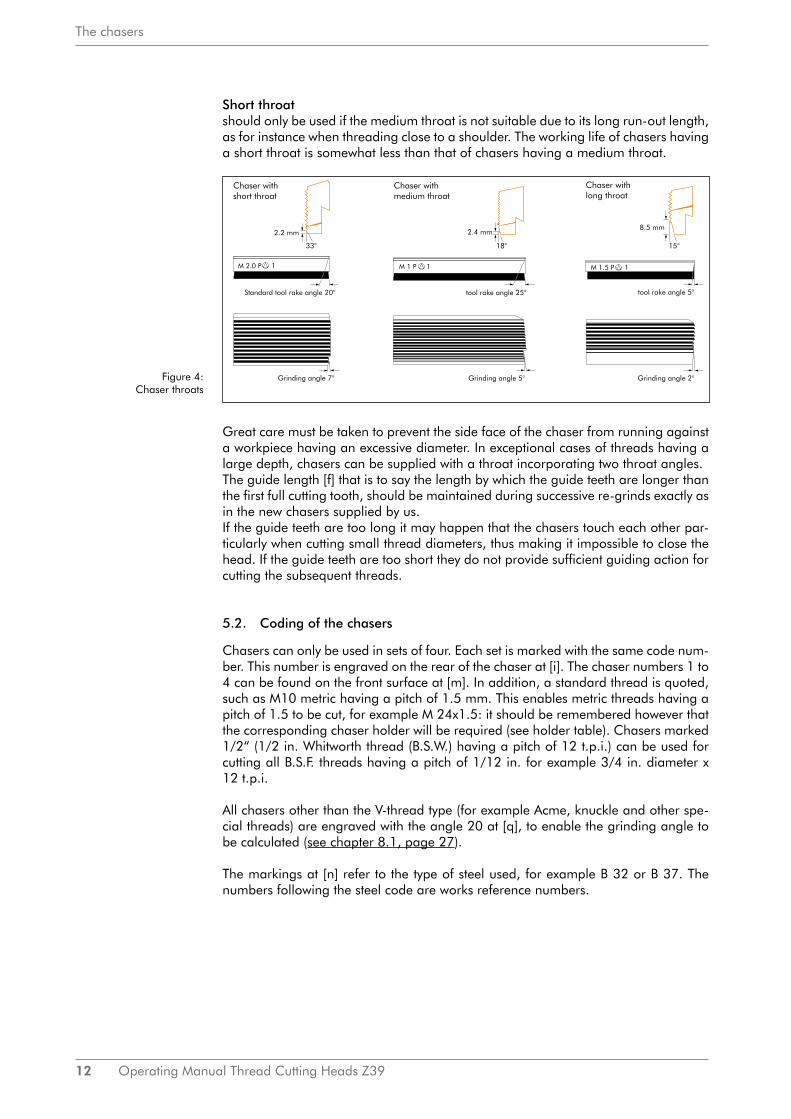
5.1. Chaser forms
The chasers cut tangentially and their main advantage in relation to radial tools is the fact that the front edge of each chaser can be re-ground as often as desired. To clarify the geometrical form of the chaser, see the three views in Fig. 6 on page 17, and the two views in Fig. 3, which are selected in that way that the front edge of the chaser appears as a straight line. Fig. 3 also shows how a clearance or relief angle may be produced by changing the setting value (see also chapter 7.1, page 17f).
Figure 3: Chaser form
The teeth directly concerned in the thread cutting process are called cutting teeth and the following teeth are known as guide teeth. During re-sharpening; which should only take place on the front face of the cutting teeth, special care must be taken to ensure that the side face of the guide teeth is not touched since this face must always coincide with a gap between the successive thread flanks if clean and uniform threads are to be obtained. The first cutting teeth are chamfered to enable the chaser to bite into the material. This is shown in Fig. 6. These first teeth represent the throat. The first full cutting tooth completes the cutting of the thread. The subsequent guide teeth engage in the thread already cut and provide the desired pitch spacing, thus dispen-sing with the need for a lead screw in many cases. The chasers can be supplied with three different throats:
Long throat is used for black material and oversize components; the chaser takes the excess ma-terial off the workpiece.
Medium throatshould be used whenever possible, but its use presupposes that accurately sized ma-terial is being threaded.
12 Operating Manual Thread Cutting Heads Z39
The chasers
Short throatshould only be used if the medium throat is not suitable due to its long run-out length, as for instance when threading close to a shoulder. The working life of chasers having a short throat is somewhat less than that of chasers having a medium throat.
Great care must be taken to prevent the side face of the chaser from running against a workpiece having an excessive diameter. In exceptional cases of threads having a large depth, chasers can be supplied with a throat incorporating two throat angles.The guide length [f] that is to say the length by which the guide teeth are longer than the first full cutting tooth, should be maintained during successive re-grinds exactly as in the new chasers supplied by us.If the guide teeth are too long it may happen that the chasers touch each other par-ticularly when cutting small thread diameters, thus making it impossible to close the head. If the guide teeth are too short they do not provide sufficient guiding action for cutting the subsequent threads.
5.2. Coding of the chasers
Chasers can only be used in sets of four. Each set is marked with the same code num-ber. This number is engraved on the rear of the chaser at [i]. The chaser numbers 1 to 4 can be found on the front surface at [m]. In addition, a standard thread is quoted, such as M10 metric having a pitch of 1.5 mm. This enables metric threads having a pitch of 1.5 to be cut, for example M 24x1.5: it should be remembered however that the corresponding chaser holder will be required (see holder table). Chasers marked 1/2“ (1/2 in. Whitworth thread (B.S.W.) having a pitch of 12 t.p.i.) can be used for cutting all B.S.F. threads having a pitch of 1/12 in. for example 3/4 in. diameter x 12 t.p.i.
All chasers other than the V-thread type (for example Acme, knuckle and other spe-cial threads) are engraved with the angle 20 at [q], to enable the grinding angle to be calculated (see chapter 8.1, page 27).
The markings at [n] refer to the type of steel used, for example B 32 or B 37. The numbers following the steel code are works reference numbers.
Figure 4: Chaser throats

Operating Manual Thread Cutting Heads Z39 13
The chasers
5.3. Chaser grades
The chasers can be supplied in two qualities
Quality B 32is the standard grade suitable for maximum continuous output when cutting threads on easily machinable material having a tensile strength of up to 85 kg/mm² (55 tons/sq. in.)
Quality B 37 is suitable for material having a high tensile strength or poor machinability. This gra-de of chaser is only supplied on special request.
5.4. Operation with or without guide teeth
The function of the guide teeth, as already mentioned, is to provide an accurate gui-ding action, so that a constant pitch is maintained without the need for a leadscrew. The guide teeth also ensure that the thread produced is truly concentric; this is ef-fected by the bracing action of the guide teeth against the thread already cut. This bracing action cannot be employed when high cutting speeds are used, since this would lead to overheating and jamming of small swarf particles between the material and the guide teeth.Pipe threads, which can sometimes be cut at speeds of up to 30 to 40 m/min (100 to 130 ft/min), are therefore always produced without the aid of guide teeth (see chapter 8.2, page 29)
5.5. Grinding the chasers
The grinding fixture should be mounted on a grinding machine having an adjustable table at right angles to the grinding wheel. The use of a WAGNER® chaser grinding machine is strongly recommended.
The grinding fixture is either swung sideways into the grinding wheel (using a stop arranged in such a way that the guide teeth are not damaged) or, if a usual tool room grinder is used, the table should be swung at right angles an horizontally to the grinding wheel and spindle.
The chaser to be ground is inserted into the fixture and clamped in position by means of the knurled screw [S4]. The grinding angle σ and the top rake γ should be set in accordance with the alignment chart (Fig. 7, page 28 and the instructions in chapter 8.1, page 27). It does not matter if wet or dry grinding methods may be used, only slight feed pressure should be applied.
When grinding dry, please take care of the temperature of the chaser. The chasers should always be able to touch.The chaser must not be immersed in water after dry grinding!
For wet grinding, a powerful jet of coolant should be directed at the cutting edge. An adequate amount of coolant should be used to protect the chaser from damage. (A rust inhibitor should be added to aqueous coolants.)Failure to observe these precautions may lead to the appearance of hairline cracks which cannot be observed with the naked eye, but which will eventually lead to failure through cracking of the chaser.Grinding wheels having a grain size of between 46 and 60 and a hardness of K or L are recommended for this purpose.
14 Operating Manual Thread Cutting Heads Z39
Thread Cutting
6. Thread Cutting
6.1. Setting the thread diameter
Setting up of the head is greatly facilitated if a sample thread is available.The following procedure should be adopted: the two socket screws [16] should be released to enable the cam ring [2] to be adjusted. Adjustment of the cam ring is effected by means of the taper key [27] which is inserted into the aperture [p] located on the circumference of the thread cutting head. Clockwise rotation of the key will close the head still further.It is of course essential that the head is closed for the setting-up procedure. The taper key should be rotated until a sample thread inserted between the chasers can just be turned by hand. The socket screws [16] should then be re-tightened, after which the first trial thread may be cut. The chaser die head is fitted with a special detent which surely prevents an unintentional displacement of the cam ring into circumferential direction in case of a sudden change of the turning direction. Before the cam ring is adjusted the inserted toothed segment [35] should always be removed by means of the taper key. After adjusting the desired thread diameter of the various delivered toothed segments, insert the segment which is suiting in the best way to the tooth system of the cam ring in the new position. Checking this thread by means of Aggra-type gauges, thread micrometers, threaded ring gauges or other Methods will indi-cate whether the diameter has been correctly adjusted. If necessary, re-adjustment must be carried out, one division of the scale being equal to approximately 0,08 mm (0.003 in.) on the diameter.
If no sample thread is available the head can be set up with the aid of a bolt whose diameter is equal to the core diameter of the desired thread.
6.2. Faulty threads and their causes
Faulty threads may be produced for a number of reasons:
1. The correct numerical sequence from 1 to t of the chaser holders has not been observed. This results in a completely distorted thread or (if the holders are inser-ted in the reverse order 4, 3, 2, 1) no thread at all.
2. Chasers from different sets may have been used. In this case the precise amount of offset between the chasers will not be achieved, thus resulting in a faulty thread.
3. The wrong set of chasers may have been inserted. For example it is impossible to produce a parallel thread with chasers for taper threads.
4. The wrong setting value or grinding angle may have been selected. This may result in the appearance of shallow, thin threads whose roots are too wide and whose flank angle is too small.
5. Faulty threads may be produced although the mistakes mentioned above were not made, for example if the material requires other setting values or other grin-ding angles and top rakes than those provided.

Operating Manual Thread Cutting Heads Z39 15
Thread Cutting
Defect: The thread is not concentric
Cause:• The four chasers are not adjusted to the same setting value.• The setting value is too small.• The material is not concentric or is sheared off.• Tie cutting speed is too low.• The top rake is too large.• The guide length [f] is too short.
The pitch is faulty
• The pitch angle of the holder is incorrect.• The wrong bolder is used.• The wrong chasers are used (for example, a Tr16x4 tread is being cut with
Tr14x4 chasers).• The grinding angle σ is not correct.• The setting value has not been adhered to.• The seed pressure is too high.• The feed pressure is too low or the slide offers too much resistance.
Wrong flank angle
The chaser is not squarely mounted in the holder (check the clamping plates and the clamping surface of the chaser).
The thread is too shallow
• The grinding angle is too small or even negative.• The setting value is too small.• The top rake is too small.
The thread are of poor quality, the flank surfaces are rough.
• This defect can be due to the formation of a double cutting edge which is often caused by selecting too small a top rake.
• The chaser is blunt.• The cutting speed is too high.• The coolant is unsuitable.
Continuous score marks on the flanks of the threads.
• The offset is wrong.• The chasers are not mounted in the corresponding holders.• Two guide teeth do not engage properly with the already cut thread.• The chaser is broken or blunt.

16 Operating Manual Thread Cutting Heads Z39
Thread Cutting
Chatter marks on the threads
• The setting value is too small.• The speed is too high.• The workpiece is clamped with excessive overhang.• The top rake is too small for soft material.
The thread is eccentric in relation to the centreline of the material
• The material is not clamped concentrically.• The slideways are no longer square to the thread, i.e. to the axis of the head.
Multiple threads are generated
The chasers are not mounted in the correct sequence.Heavy feed pressure may result in the production of multiple-start threads when cut-ting fine threads of a comparatively large diameter. The chaser will then automati-cally continue to cut these multiple threads.
The chaser jaws are broken
• The diameter of the material is too large.• The material is not concentric or is sheared off. • The setting value is too small.• The speed is too low.
6.3. Cooling
Normally, thread cutting should only be carried out with the aid of a supply of coolant.Water-soluble drilling oil can be used, but cutting oil is to be preferred if it is desired to produce clean threads.This will also considerably increase the working life of the chasers.
Operating Manual Thread Cutting Heads Z39 17
Tables & associated descriptions
7. Tables & associated descriptions
7.1. Instructions for the use of the setting tables
To ensure that the chasers are uniformly set in the correct relationship to the workpi-ece, they are adjusted in a setting device by means of a dial indicator. An accuracy of a few hundredths of a millimetre may be considered adequate. The desired values can be obtained from the setting table to an accuracy of 0.05 mm. The top row lists a large variety of customary threads. Since the setting value depends on the minor thread diameter, this is listed in the first column. The second column gives the setting length. This is the dimension between the point of contact of the chaser with the work-piece (assuming that the chaser is accurately set to the centreline of the workpiece) and the centreline of the holder pin. By subtracting half the diameter of the setting gauge from the setting length, the setting values listed in the third and fourth columns are obtained. It is immaterial which of the two steps of the setting gauge is used. In general however it is recommended that the step with the larger diameter be used, as this provides the smaller setting value. This facilitates counting the full millimetres as rotations of the large hand of the dial indicator.
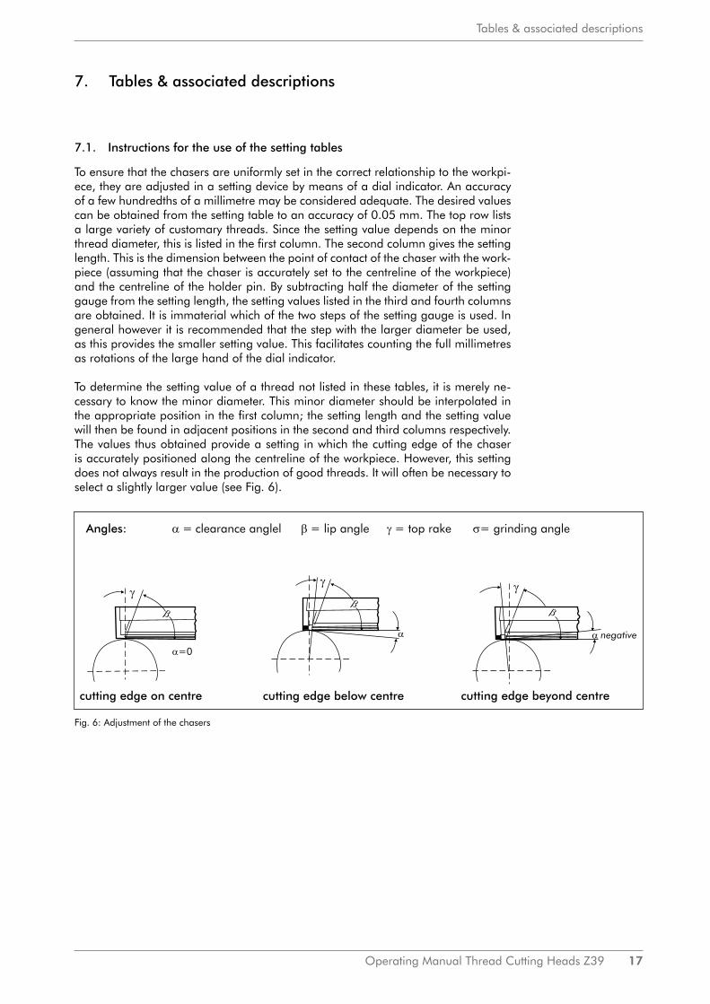
To determine the setting value of a thread not listed in these tables, it is merely ne-cessary to know the minor diameter. This minor diameter should be interpolated in the appropriate position in the first column; the setting length and the setting value will then be found in adjacent positions in the second and third columns respectively.The values thus obtained provide a setting in which the cutting edge of the chaser is accurately positioned along the centreline of the workpiece. However, this setting does not always result in the production of good threads. It will often be necessary to select a slightly larger value (see Fig. 6).
Fig. 6: Adjustment of the chasers
18 Operating Manual Thread Cutting Heads Z39
Tables & associated descriptions
If you want to cut threads in soft material it will be necessary to place the cutting edge beyond the centreline of the workpiece.
In other words, the setting value must be increased if the threads produced with the normal setting value are not fully concentric. It is recommended that the value be in-itially increased by only 1%. Further adjustment of the chaser may be required if this does not produce the desired results.Depending on the type of thread to be cut end material used, it may be necessary to increase the value by as much as 3% of the diameter. In effecting these adjustments it must be remembered that the cutting temperature is always increased if the chaser acts at a point beyond the centreline of the workpiece. The setting value should there-fore not be increased more than absolutely necessary to produce the desired clean threads.
7.2. Instructions for using the table of chaser holders
The table of chaser holders enables the user to select the appropriate holder in ac-cordance with his requirements. The head of the table contains a large number of standard threads which include German, English and American threads.
The first column lists all normal chaser holders which can be supplied for any parti-cular chaser head.The second column lists the holder angle, then follows a column giving the dimen-sions of the chaser. In this last column the first two figures refer to the cross-section of the chaser and the last figure to the length of a new chaser. Re-sharpening will of course reduce this length.The minimum and maximum core diameters which can be cut with the particular holder are quoted in the fourth column.
The quality or grading of the thread is divided into three classes in accordance with DIN (German Standards), that is to say, close, medium and coarse tolerance.To cut a close-tolerance thread it will be necessary to select the correct relationship between the holder angle and the helix angle of the thread. It is not possible to cut a close-tolerance thread using a holder whose diameter range corresponds only to the minor diameter. In the table, therefore, all threads coming within the close-tolerance range are marked by being placed in brackets. The first two groups of holders refer to a fairly large range and naturally incorporate only a few threads within the close-tolerance range. The other holders are intended mainly for close-tolerance threads, but it is also possible to cut some additional threads within the medium-tolerance range.
Metric and wood threads are indicated by a figure which appears in the form of a fraction under the main figure, which indicates the pitch of the thread in mm. The figures corresponding to the numerator of such a fraction contain one or more num-bers which refer to the external diameter of the thread.
Special holders are required for cutting Acme threads with the aid of a leadscrew. These holders are marked with the corresponding holder angle. The note in the table “To be cut only with leadscrew” should he carefully observed.

Operating Manual Thread Cutting Heads Z39 19
Tables & associated descriptions
7.3. Setting tables Z39
R
d 38
x1/8
"
M36
x0,7
5
M35
x0,7
5M
36x1
Setti
ngga
uge
Ø 8
2
5,95
5,90
R 1
.1/8
"
M33
x1
M34
x2
47,0
00,
00M
35x0
,5M
36x1
,25
0,05
M36
x1,5
W1.
1/2-
1/8"
47,1
00,
1039
M35
x1
0,15
M34
x0,5
M
36x2
FG34
,8
Rd3
6x1/
8
47,2
00,
20M
34x0
,75
M35
x1,5
1 1/
2-6
M34
x11
1/2
47,3
00,
30M
33x0
,5 M
35x2
M33
x0,7
5 M
34x1
,25
M34
x1,5
FG32
,77
34,8
4
35,1
6
34,5
1
47,4
0
47,3
5
47,2
5
47,1
5
33,1
6
33,5
0
33,8
4
34,1
8
31,7
3
31,3
5
47,0
5
46,9
46,9
5
32,1
0
32,4
5
32,8
1
0,40
0,35
0,25
47,4
50,
45M
32x0
,5 M
32x0
,75
M33
x1,5
47,5
00,
5036
M32
x1W
1.3
/8-1
/8"
Rd3
4x1/
8
R1
G1
47,5
50,
55M
30x0
,5 M
32x1
,25
47,6
00,
60M
32x1
,5
1"-1
1,5
TPI
47,6
50,
651
3/8
47,7
00,
70M
32x2
Rd3
2x1/
81
1/4-
1247
,75
0,75
M30
x0,7
5 M
30x1
47,8
00,
8033
M30
x1,2
5
R7/
8 G
7/8
47,8
50,
85M
30x1
,5W
1.1/
4-1/
9
47,9
00,
90M
28x0
,5 M
30x2
1 1/
4-7
47,9
50,
95M
28x0
,75
1 1/
4
48,0
01,
00M
27x0
,5 M
28x1
Rd3
0x1/
8P
g21
29,0
0
29,4
0
29,9
1
30,2
30,5
9
30,9
8
26,3
4
26,8
1
27,2
7
27,7
1
28,1
5
28,5
7
Cor
e-Ø
Setti
ngle
ngth
Setti
ngga
uge
Ø 9
4
Met
ricth
read
sD
IN 1
3
Met
ric fi
ne th
read
sD
IN 1
3B
SW th
read
sD
IN 1
1
Woo
dth
read
s lo
c.
stan
dard
2426
2
Knu
ckle
thre
ads
DIN
405
Con
duit
thre
ads
DIN
404
30N
PTU
NC
(NC
)U
NF
(NF)
BSF
thre
ads
BSP
thre
ads
Am
eric
an N
atio
nal T
hrea
ds
DIN
FA
FA4
Acm
eth
read
s D
IN
903
Woo
dth
read
s

20 Operating Manual Thread Cutting Heads Z39
Tables & associated descriptions
PG
36
BSF threads
NPT
Core-Ø
Setting lengthSetting gauge
Ø 82
Metric fine
threads DIN
13
42,48
42,73
M45x2
BSP threads
42,98
43,22
43,46
41,72
41,99
43,71
45,704,7
45,654,65
45,604,60
42,23
45,554,55
45,504,50
45,454,45
M45x1,5
45,404,40
M45x1,25
4,25M
45x0,75
45,354,35
M45x1
45,304,30
46,69
46,91
47,13
43,95
45,25
45,20
45,10
45,00
44,9
45,35
45,05
44,80
44,75
44,60
45,57
45,80
46,03
46,25
46,47
44,18
44,42
44,65
44,89
45,12
4,20M
45x0,5M
48x3
45,154,15
4,10R
1 1/2 G1 1/2
3,9
44,853,85
4,05
4,00
44,953,95
M48x2
3,60M
48x0,75
R1 3/8 G
1 3/8
M42x1,5
M42x1,25
M42x1
M42x0,75
M42x0,5
M45x3
3,75M
48x1,25M
50x3
44,703,70
44,653,65
M48x1
3,80M
48x1,5
40,94
41,21
41,46
41,72
45,804,80
45,754,75
45,904,90
45,854,85
39,88
M40x0,75
M40x0,5 M
42x2
40,14
40,40
46,055,05
5,20
46,255,25
39,60
46,005,00
45,954,95
40,67
Rd 42x1/6
M38x1,5
M38x1,25
M39x2
M39x0,75
M40x1,5
M39x0,5
M40x1,25
M40x1
Rd 44x1/6"
R1 1/4
G1 1/4
M36x0,5
M38x2
1 1/2-12P
G29
46,105,10
46,155,15
46,20
46,355,35
46,405,40
46,455,45
46,55,5
46,555,55
1 1/4" - 11,5
M38x1
M38x0,75
M39x1,5
M38x0,5
M40x2
M39x1
Rd 40x1/6
46,605,60
38,77
39,05
39,33
46,855,85
46,755,75
46,655,65
37,02
37,32
37,62
37,91
38,20
38,48
35,16
35,48
35,79
46,705,70
46,305,30
1 1/2" - 11,5 TPI
36,11
36,41
36,72
Knuckle threads
DIN
405C
onduit threadsD
IN 40430
NPT
UN
F (NF)
BSF
threadsB
SP threadsA
merican N
ational ThreadsC
ore-ØSettinglength
SettinggaugeØ
82
Metric fine
threads DIN
13
46,805,80

Operating Manual Thread Cutting Heads Z39 21
Tables & associated descriptions
42,2
51,
25
Pg4
2
M58
x1
M58
x0,7
5
M60
x2
Pg4
8
M60
x1,5
M62
x3
M60
x1,2
5
M60
x1
M60
x0,7
5
41,0
00,
003,
00
56,0
8
56,2
4
56,4
1
Cor
e-Ø
58,8
3
56,7
4
56,9
1
57,0
7
57,2
4
57,4
0
57,5
6
57,7
2
57,8
9
56,5
8
58,0
5
58,2
0
58,3
6
58,5
2
58,6
8
59,2
9
59,4
5
59,6
0
59,8
4
59,1
6
58,9
9
42,2
01,
20M
58x1
,5
42,1
01,
10M
58x1
,25
41,7
50,
75
41,8
00,
80
41,6
00,
60
41,7
0,7
41,6
50,
65
Setti
ng le
ngth
Setti
ng g
auge
Ø 8
2
Met
ric fi
ne
thre
ads
DIN
13
BSF
thre
ads
BSP
thre
ads
42,1
51,
15M
60x3
Setti
ng g
auge
Ø 7
6
42,0
01,
00
42,0
51,
05
41,8
50,
85
41,9
00,
90
41,9
50,
95
R2
G
2
41,3
0
41,4
50,
45
41,5
00,
50
41,5
50,
55
0,30
3,30
41,3
50,
353,
35
41,4
00,
403,
403,7
3,65
3,60
3,55
3,50
3,45
3,25
3,20
3,15
41,1
00,
103,
10
41,1
50,
15
M62
x2
41,2
50,
25
41,2
0,20
Cor
e-Ø
Eins
telll
änge
Setti
ng g
auge
Ø 8
2
Met
ric fi
ne
thre
ads
DIN
13
NPT
BSP
thre
ads
51,7
8
51,9
8
52,1
6
52,3
5
2,3
M56
x3
43,2
52,
25
52,5
3
52,7
2
52,9
1
53,0
8
53,2
7
53,4
5
53,6
3
43,4
02,
40
43,3
52,
35
43,3
0
M55
x2
43,0
52,
05M
55x1
,5
43,0
02,
00M
56x2
43,2
02,
20
43,1
52,
15
43,1
02,
10
1,75
42,3
01,
30
M55
x0,7
5M
56x1
,5
42,9
51,
95M
55x1
,25
42,9
01,
90M
55x1
55,9
1
54,8
8
55,0
5
55,2
2
55,3
9
42,6
51,
65
42,6
01,
60M
56x1
42,5
51,
55
42,4
01,
40
55,5
6
42,5
1,5
M56
x0,7
5
42,4
51,
45M
58x2
53,8
1
42,3
51,
35
M58
x3
55,7
3
54,0
0
54,1
7
54,3
5
52,5
2
54,7
0
42,8
51,
85
42,8
01,
80
42,7
01,
70
42,7
5
2" -
11,5
TP
I2,
45
43,6
02,
60M
52x0
,75
43,5
52,
55M
55x3
51,5
9
51,7
8
50,8
2
43,6
52,
65
43,5
02,
50
43,4
5
R1
3/4
G1
3/4
47,5
6
51,0
2
51,2
1
51,4
43,7
52,
75M
52x1
,25
43,8
52,
85M
52x1
M52
x1,5
M52
x2
43,9
52,
95
44,0
53,
05M
50x0
,5
3,20
44,1
53,
15M
50x1
R1
5/8
G1
5/8
3,25
M50
x1,2
5
44,3
53,
35M
50x1
,5
44,1
3,1
M50
x0,7
5
44,4
53,
45
44,4
03,
40
43,7
02,
70
43,8
02,
80
43,9
02,
90
44,0
03,
00
44,2
0
44,3
03,
30M
52x3
44,2
5
50,0
4
50,2
3
50,4
3
50,6
2
47,7
7
47,9
9
48,2
48,4
48,6
1
48,8
2
49,0
3
49,2
3
49,4
3
49,6
3
49,8
4
Met
ric fi
ne th
read
sD
IN 1
3B
SFth
read
sSe
tting
leng
thC
ore-
ØSe
tting
gau
geØ
82
47,1
3
47,3
4
44,5
53,
55
44,5
03,
50M
48x0
,5M
50x2

22 Operating Manual Thread Cutting Heads Z39
Tables & associated descriptions
0,6M
68x133,9
2,9
Core-Ø
73,92
74,13
74,34
74,54
36,15,1
Setting lengthSetting gauge
Ø 62
Metric fine
threads DIN
13
BSP threads
36,2R
2 1/2G
2 1/2
36,0
35,9
5,0
4,9
35,6
35,5
35,7M
76x2
4,8
35,2
35,14,1
35,4
35,3
34,7M
78x2
3,8
35,0
M79x3
74,75
74,95
75,15
75,35
75,55
34,9
4,0
3,9
M75x2
M75x1,5
M77x3
72,21
72,44
72,65
72,87
73,08
73,29
35,8
76,34
76,54
76,73
76,92
3,7
4,7
4,6
4,5
4,4
4,3
75,75
34,5
34,63,6
73,5
73,72
34,8
4,2
M76x1,5
M78x3
M77x2
34,4M
78x1,5
75,95
76,15
3,1
3,0
34,1
34,0
3,5
3,4
3,3
3,2
34,3
34,2
M80x3
M79x2
BSP threads
38,50,5
38,40,4
M68x0,75
Metric fine
threads DIN
13
69,24
69,48
69,72
62,48
62,78
2,9M
62x1,5M
64x3
Setting lengthSetting gauge
Ø 76
Metric fine
threads DIN
13
2,8
2,7M
62x1
2,3M
64x1,5
2,6M
62x0,75M
65x3
2,5M
62x1,25M
64x2
2,4
Core-Ø
60,15
60,45
60,75
61,05
61,34
61,63
40,8
40,7
40,3
40,6
40,5
40,4
61,92
62,21
1,8M
65x1,25
40,02,0
M64x1
39,91,9
M64x0,75
64,97
63,06
63,34
39,8
65,24
65,50
R2 1/4
G2 1/4
63,89
1,7M
65x1
39
65,77
2,1
1,4
39,31,3
1,2
39,1
66,03
66,28
66,54
66,80
67,05
64,16
64,43
64,70
63,62
67,79
68,04
39,7
39,6
39,4
40,22,2
M65x2
40,1
39,51,5
M68x3
67,30
67,55
1,1M
68x2
39,2
38,70,7
M68x1,25
M70x3
R2 3/8
G2 3/8
38,8
1,0
38,30,3
M70x2
38,20,2
68,77
69,0
BSP threads
Core-Ø
Setting lengthSettinggaugeØ
76
Setting gaugeØ
62
72,0
68,28
37,9
37,7
37,5
37,3
37,1
69,95
70,18
70,42
37,8
71,33
71,55
71,78
70,65
70,87
71,1
37,2
6,3
6,2M
72x1,5
68,53
37,6
6,7
6,6
37,0
6,1
6,0
M74x3
36,95,9
5,8
36,7
36,6
5,7
5,6
36,4
5,5
5,4
38,6
0,8M
68x1,5
38,90,9
72,21
M70x1,25
M71x2 M
72x3
M70x1
M70x0,75
M72x2
36,3
M73x2
M75x3
M74x2
5,3
36,5
36,8
37,4
6,5
6,4
1,6
40,905,2
M76x3
6,9
6,8
38,1
38,0
0,10M
70x1,5

Operating Manual Thread Cutting Heads Z39 23
Tables & associated descriptions
33,9
2,9
88,3
2
31,5
0,5
M83
x388
,32
25,1
88,4
5
88,5
8
88,7
1
88,8
4
88,9
7
89,0
9
89,2
2
89,3
4
89,9
5
25,5
1,7
1,6
1,5
1,4
1,3
1,2
1,1
90,0
8
90,2
90,3
2
90,4
4
Setti
ngle
ngth
Setti
ng g
auge
Ø 5
0
Met
ric fi
ne
thre
ads
DIN
13
BSP
thre
ads
Cor
e-Ø
89,4
6
89,5
9
89,7
1
89,8
4
26,7
26,6
26,3
26,0
25,7
26,2
26,1
M91
x1,5
26,5
26,4
25,9
25,8
25,6
1,0
0,9
M93
x3
90,5
5
M91
x2
0,8
0,7
0,6
25,4
25,3
25,2
25,0
0,5
0,4
0,3
0,2
0,1
0,0
27,7
27,6
27,5
27,4
27,3
27,2
27,1
27,0
2,9
26,8
M89
x1,5
M90
x2M
91x3
M90
x1,5
M92
x31,
8
87,9
3
88,0
6
2,0
1,9
26,9
28,1
3,1
28,0
3,0
2,8
2,7
2,6
2,5
2,4
2,3
2,2
2,1
27,9
27,8
3,3
28,2
3,2
M89
x2M
90x3
3,5
28,4
3,4
M88
x1,5
85,5
8
28,7
3,7
28,6
3,6
85,2
9
28,9
3,9
M88
x2M
89x3
85,4
4
28,8
3,8
4,1
M87
x1,5
29,0
4,0
Met
ric fi
ne
thre
ads
DIN
13
Cor
e-Ø
Setti
ngle
ngth
Setti
ng g
auge
Ø 5
0
Met
ric fi
ne
thre
ads
DIN
13
31,4
31,3
0,4
0,3
BSP
thre
ads
M84
x2
Setti
ng g
auge
Ø 5
0
81,3
9
81,5
6
Setti
ngle
ngth
Setti
ng g
auge
Ø 6
2
Met
ric fi
ne
thre
ads
DIN
13
Cor
e-Ø
M81
x1,5
M83
x3
M82
x2
2,4
2,7
2,6
M80
x1,5
M82
x3
2,3
2,2
2,5
0,8
0,7
0,6
1,1
1,0
M84
x3
M83
x2
1,9
1,8
1,7
1,6
1,5
1,4
1,3
M83
x1,5
M82
x1,5
0,9
1,2
83,6
4
83,7
9
85,9
5
81,7
2
84,4
31,2
81,8
8
31,1
31,0
30,9
30,8
30,7
82,0
5
82,2
1
M84
x1,5
84,1
84,2
5
82,3
7
82,5
3
82,6
9
82,8
5
30,6
M86
x3
M85
x2
30,5
30,4
M85
x1,5
29,7
M86
x1,5
29,6
M88
x34,
6
29,9
29,8
5,8
4,4
5,2
5,1
5,0
4,9
4,8
4,7
5,7
5,6
5,5
5,4
5,3
81,2
2
88,1
9
86,0
1
86,1
5
86,3
86,4
4
86,5
7
86,7
1
86,8
5
R2
3/4
G2
3/4
31,6
4,2
84,7
84,8
5
85,0
84,5
5
29,5
4,5
29,4
R3
G3
M87
x2
M81
x22,
1
M80
x2
M81
x3
29,1
87,2
6
87,4
87,5
3
87,6
7
87,8
85,7
3
85,8
7
28,5
28,3
29,3
4,3
29,2
0,2
0,1
0,0
5,9
87,1
3
32,5
86,9
9
32,7
83,0
1
83,1
7
32,9
2,0
30,1
30,0
30,3
M87
x3
30,2
M86
x2
83,3
3
83,4
8
79,1
5
79,3
2
33,3
31,8
31,7
32,0
31,9
32,2
32,1
32,3
33,1
85,1
5
77,4
9
77,6
8
77,8
7
80,5
4
80,7
1
80,8
8
81,0
5
78,2
4
33,2
33,0
32,8
32,6
32,4
79,5
79,6
7
79,8
5
80,0
2
80,2
80,3
7
78,4
3
78,6
1
78,7
9
78,9
7
78,0
6
77,1
1
77,3
Cor
e-Ø
Setti
ngle
ngth
BSP
thre
ads
Setti
ng g
auge
Ø 6
2
33,6
33,5
33,8
33,7
33,4
M79
x1,5
2,8

24 Operating Manual Thread Cutting Heads Z39
Tables & associated descriptions
7.4. Holder tables Z39
WAGNER-WERKZEUGSYSTEMEMÜLLER GmbHGutenbergstrasse 4/1D-72124 PliezhausenTel. 07127/973 300Telefax: 07127/973 390email: [email protected]
Chaser holder Cutting range Metric Metric fine threads Whitworth- B S F Whitworth- American National Threads Steel conduit KnuckleDesignation Holder angle Dimension of Core diameter threads DIN 246, 247, threads threads pipe threads NPT NC NF pipe threads threadsProduct-No. in ° chasers in mm DIN 13 516-519 DIN 11 DIN 259 NPS UNC UNF DIN 40430 DIN 405
5/16" 5/16-18Z39/1D 4,08° 22x10x68 4,7 - 18,5 M5* 3/8" 3/8-16
70553000 M6 7/16" 7/16-141/2"
Z39/2D 3,50° 22x10x68 4,7 - 18,5 M7-14 9/16" 1/2-1370553700 5/8" W5/16"x1/22" 9/16-12
5/8-113/4" 3/4-10
Z39/3D 3,08° 25x12x75 10,5 - 24,2 M16-24 7/8" 7/8-9 Rd 22-26x1/8"70554700 1" 1-8
1.1/8" 1.1/8-71.1/4" 1.1/4-7 Rd 26x1/8"
Z39/4D 2,75° 25x12x75 20,5 - 33,8 M27-39 1.3/8" 1.3/8-6 Rd 28x1/8"70555200 1.1/2" 1.1/2-6 Rd 30x1/8"
Rd 32x1/8"M10-12x1 R1/8" 1/4-18 1/2-20
Z39/20D 2,41° 25x12x75 6,5 - 20,2 M12-15x1,25 W11/16"x1/14" R1/4" 3/8-18 9/16-18 Pg 7-970553900 M14-18x1,5 W13/16"x1/12" R3/8" 1/2-14 5/8-18
M19-22x2 R1/2" 3/4-16R5/8" 1-14
Z39/21D 1,83° 25x12x75 20,5 - 33,8 M23-27x1,5 R3/4" 3/4-14 1.1/8-12 Pg 16-2170555100 + M25-36x2 R7/8" 1-11.1/2 1.1/4-12
R1" ~ 1.3/8-12R1.1/8" ~
Z39/22D 1,58° 25x12x75 33 - 45,7 M36-48x2 R1.1/4" ~ 1.1/4-11.1/2 1.1/2-12 Pg 29-3670555400 + M45-48x3 R1.3/8" ~ 1.1/2-11.1/2
R1.1/2" ~Z39/23D 1,41° 25x12x75 47,3 - 58,8 M50-60x1,5 R1.5/8" ~72462000 1.5/12° # M50-60x2 R1.3/4" ~ Pg 42-48
M52-62x3 R2" ~
+ For thread diameter over 45 mm max. thread length 30 mm including throat# Thread length including throat 34 mm* with special sliding pads 8,5 mm thickness~ Only cylindrical threads becuase of chaser width
Holder table for thread cutting head Z 39, ZE 39, ZM 39
1/3
21.09.2016
WAGNER-WERKZEUGSYSTEMEMÜLLER GmbHGutenbergstrasse 4/1D-72124 PliezhausenTel. 07127/973 300Telefax: 07127/973 390email: [email protected]
Chaser holder Cutting range Metric Metric fine threads Whitworth- B S F Whitworth- American National Threads Steel conduitDesignation Holder angle Dimension of Core diameter threads DIN 246, 247, threads threads pipe threads NPT NC NF pipe threadsProduct-No. in ° chasers in mm DIN 13 516-519 DIN 11 DIN 259 NPS UNC UNF DIN 40430
Z39/69D 3,08° 22x10x68 4,7 - 18,5 M11 M8x1 W3/8"x1/20"70553100 M16 M10x1,25 W7/16"x1/18" 5/16-24
M20 M12-13x1,5 W1/2"x1/16"M7-8x0,75 W9/16x1/16" 3/8-24
Z39/70D 2,60° 22x10x68 4,7 - 18,5 M9-10x1 W5/8"x1/14" R1/8" 7/16-20 Pg 770553800 M11-13x1,25 W11/16"x1/14" R1/4" 1/2-20 Pg 9
M13-16x1,5 W3/4"x1/12" 9/16-18M18-21x2 W13/16"x1/12"
M8-10x0,75 R1/8" 1/2-20Z39/71D 2,20° 22x10x68 6,5 - 20,2 M10-14x1 R1/4" 1/8-27 9/16-18 Pg 7
70554000 M12-17x1,25 R3/8" 1/4-18 5/8-18 Pg 9-11M15-21x1,5 R1/2" ~ 3/8-18 3/4-16
7/8-14M17-20x1 Pg 11
Z39/72D 1,75° 22x10x68 15 - 28,5 M18-25x1,25 R3/4" ~ 3/4-14 1-14 Pg 13,570555000 M20-30x1,5 R7/8" ~ 1.1/8-12 Pg 16
M27-30x2 Pg 21Z39/74D 1,33° 22x10x68 26,2 - 39,5 M28-40x1,25 Pg 21
70555300 M30-41x1,5 R1.1/4" 1.1/4-11.1/2 ~ 1.9/16-18 Pg 29M38-42x2
M40-52x1,25Z39/75D 1,08° 22x10x68 38,3 - 50,5 M42-52x1,5 1.1/2-11.1/2 ~ Pg 36
70555500 + M45-52x2M40-51x1
+ For thread diameter over 45 mm max thread length 33 mm including throat~ Only cylindrical threads because of chaser width
Holder table for thread cutting head Z 39, ZE 39, ZM 39
2/3
21.09.2016
Operating Manual Thread Cutting Heads Z39 25
Tables & associated descriptions
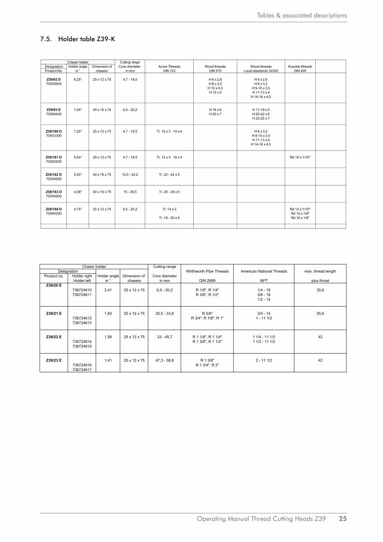
7.5. Holder table Z39-K
WAGNER-WERKZEUGSYSTEMEMÜLLER GmbHGutenbergstrasse 4/1D-72124 PliezhausenTel. 07127/973 300Telefax: 07127/973 390email: [email protected]
Chaser holder Cutting rangeDesignation Holder angle Dimension of Core diameter Acme Threads Wood threads Wood threads Knuckle threadsProduct-No. in ° chasers in mm DIN 103 DIN 570 Local standards 24262 DIN 405
Z39/92 D 8,25° 25 x 12 x 75 4,7 - 18,5 H 6 x 2,6 H 6 x 2,670553600 H 8 x 3,5 H 8 x 3,2
H 10 x 4,5 H 9-10 x 3,5H 12 x 5 H 11-13 x 4
H 14-16 x 4,5
Z39/93 D 7,00° 40 x 16 x 75 6,5 - 20,2 H 16 x 6 H 17-19 x 570554400 H 20 x 7 H 20-22 x 6
H 23-25 x 7
Z39/180 D 7,20° 25 x 12 x 75 4,7 - 18,5 Tr. 10 x 3 . 14 x 4 H 8 x 3,270553300 H 9-10 x 3,5
H 11-13 x 4H 14-16 x 4,5
Z39/181 D 5,83° 25 x 12 x 75 4,7 - 18,5 Tr. 12 x 3 . 16 x 4 Rd 10 x 1/10"70553500
Z39/182 D 5,00° 40 x 16 x 75 10,5 - 24,2 Tr. 22 - 24 x 570554600
Z39/183 D 4,08° 40 x 16 x 75 15 - 28,5 Tr. 26 - 28 x 570554900
Z39/188 D 4,75° 25 x 12 x 75 6,5 - 20,2 Tr. 14 x 3 Rd 12 x 1/10"70554200 Rd 15 x 1/8"
Tr. 18 - 20 x 4 Rd 16 x 1/8"
Holder table for thread cutting head Z 39, ZE 39, ZM 39
3/3
21.09.2016
WAGNER-WERKZEUGSYSTEMEMÜLLER GmbHGutenbergstrasse 4/1D-72124 PliezhausenTel. 07127/973 300 Table of chaser holders for thread cutting head Z 39 K (= tapered) 1:16Telefax: 07127/973 390email: [email protected]
Chaser holder Cutting rangeWhithworth Pipe Threads American National Threads max. thread length
Holder right Holder angle Dimension of Core diameterHolder left in ° chasers in mm DIN 2999 NPT plus throat
Z39/20 E736724610 2,41 25 x 12 x 75 6,5 - 20,2 R 1/8", R 1/4" 1/4 - 18 35,6736724611 R 3/8", R 1/2" 3/8 - 18
1/2 - 14
Z39/21 E 1,83 25 x 12 x 75 20,5 - 33,8 R 5/8" 3/4 - 14 35,6736724612 R 3/4", R 7/8", R 1" 1 - 11 1/2736724613
Z39/22 E 1,58 25 x 12 x 75 33 - 45,7 R 1 1/8", R 1 1/4" 1 1/4 - 11 1/2 42736724614 R 1 3/8", R 1 1/2" 1 1/2 - 11 1/2736724615
Z39/23 E 1,41 25 x 12 x 75 47,3 - 58,8 R 1 5/8" 2 - 11 1/2 42736724616 R 1 3/4", R 2"736724617
DesignationProduct no.

26 Operating Manual Thread Cutting Heads Z39
Tables & associated descriptions
7.6. Special holder table Z 39
ThreadCore diameter
Chaser holder DesignationProduct no.
ChaserOrder information
Setting deviceProduct no.
Setting gauge diameter
Setting value
Operating Manual Thread Cutting Heads Z39 27
Angles
8. Angles
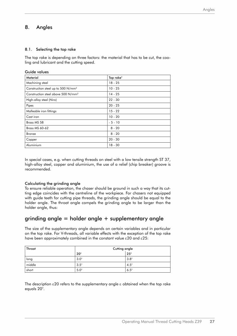
8.1. Selecting the top rake
The top rake is depending on three factors: the material that has to be cut, the coo-ling and lubricant and the cutting speed.
Guide valuesMaterial Top rake°
Machining steel 18 - 25
Construction steel up to 500 N/mm² 10 - 25
Construction steel above 500 N/mm² 14 - 25
High-alloy steel (Niro) 22 - 30
Pipes 20 - 25
Malleable iron fittings 15 - 22
Cast iron 10 - 20
Brass MS 58 - 5 - 10
Brass MS 60-62 8 - 20
Bronze 8 - 20
Copper 20 - 30
Aluminium 18 - 30
In special cases, e.g. when cutting threads on steel with a low tensile strength ST 37, high-alloy steel, copper and aluminium, the use of a relief (chip breaker) groove is recommended.
Calculating the grinding angleTo ensure reliable operation, the chaser should be ground in such a way that its cut-ting edge coincides with the centreline of the workpiece. For chasers not equipped with guide teeth for cutting pipe threads, the grinding angle should be equal to the holder angle. The throat angle compels the grinding angle to be larger than the holder angle, thus:
grinding angle = holder angle + supplementary angle
The size of the supplementary angle depends on certain variables and in particular on the top rake. For V-threads, all variable effects with the exception of the top rake have been approximately combined in the constant value ε20 and ε25:
Throat Cutting angle
20° 25°
long 3.0° 3.8°
middle 3.5° 4.5°
short 5.0° 6.5°
The description ε20 refers to the supplementary angle ε obtained when the top rake equals 20°.

28 Operating Manual Thread Cutting Heads Z39
Angles
Example 1:It is desired to grind a chaser for an M 10 metric thread, medium throat, top rake 20°. The holder angle will be 3.8°, the supplementary angle referred to a top rake of 20° amounts to 3.5. The grinding angle will therefore be equal to 3.8 + 3.5 = 7.3°The alignment chart should be used if a top rake other than 20° is to be used.
Example 2:It is desired to cut a 1/2-inch B.S.P. thread having a top rake of 15° and a short th-roat. The angle ε20 amounts to 6.8° in accordance to the table for a short throat. This angle is marked or the scale „Additional angles for 20° top rake”. In drawing a connecting line on the inclined top rake reference through the point 15°, the figure 4.9° will be obtained in the scale giving the supplementary angle. The holder angle amounts to 3.8°, the grinding angle will therefore be equal to 3.8 + 4.9°.
For threads other than V-threads (Acme, knuckle or wood threads) the expression ε20 can no longer be given as a constant. In such cases the angle ε20 is therefore engraved on the underside of chaser No 1 of each set.
Example 3:A chaser for an Acme thread is to be ground to a top rake of 15°. The angle ε20 is given as 6° on the underside of the chaser. The vaIue 6° should now be found on the ε20-scale.This point should then be connected to the top rake = 15°, thus providing the supple-mentary angle of 4.4°. The holder angle must be added to this supplementary angle.
Checking the grinding angle with the setting deviceThe value γ thus calculated ensures that the cutting edge is parallel to the centreline of the workpiece. It is however possible treat in certain materials this is not entirely desirable, for instance when cutting stainless steels (VA steels). It may then be advisa-ble to reduce the grinding angle d considerably, and in certain circumstances it may even be necessary to have a negative grinding angle.Chasers supplied by our works are ground for normal metric or Whitworth threads. For fine threads the chaser must be ground in accordance with these instructions.
Figure 7: Alignment chart for cutting
angle
ExampleFirst cut angle: 18° (middle)Top rake: 15°
Additional angle: 2.6°

Operating Manual Thread Cutting Heads Z39 29
Angles
8.2. Calculating the cutting speed
For normal practice of obtaining accurate data concerning cutting speeds and tools used when turning various materiaI is well known. It is not possible to obtain such data for thread cutting, since in this case the cutting speed depends on many variables including the workpiece, diameter, thread, depths, pitch, setting value, top rake, grinding angle and on the required quality of surface finish on the thread flanks. The table given below therefore provides merely an ap-proximate guide which will facilitate the selection of the correct cutting speed for any given application.
The first column in this table contains only a few materials. Materials not mentioned should be interpolated as appropriate between two of the materials quoted. The second column quotes cutting speeds when cutting V-threads. Please note that the lower cutting speed always refers to the larger diameter while the higher cutting speed refers to the smaller diameter.
The following approximate rule should be adopted for cutting fine threads: A thread of the same pitch as the desired fine thread should be found from the standard range of threads. The corresponding cutting speed should then be selected for the fine th-read. The third column “Acme threads” also contains a range of cutting speeds which should be selected in accordance with the diameter of the workpiece (small diameters require higher cutting speeds).
Material Cutting speeds [m/min]
Normal V-threads Acme threads
Free cutting steel 10 - 20 4 - 6
C 35 10 - 15 4 - 6
C 60 3 – 6 3 - 5
VCMo 135 2 - 4 2 - 4
VA-steels 3 - 5 1,5 - 3
Brass and bronze 15 and higher 8 and higher
Threads for pipes and pipe fittings may be cut on a great variety of material. The cutting speeds for the range of 10 to 20 m/min. If it is possible for the pipe to project for some distance beyond the vice in such a way that it vibrates or “sings” during the cutting process, it may be possible to cut dry to use cutting speeds of 30 to 40 m/min.Then the flanks of the threads, however, will not have a high surface finish. The cor-rect cutting speed must be found by trial and error from case to case.
Figure 8:Checking the grinding angle with the setting device

30 Operating Manual Thread Cutting Heads Z39
Angles
Instructions for using the thread cutting speed alignment chart
The left-hand scale »d« contains major diameters in millimetres and inches as well as the major diameters for Whitworth pipe threads (B.S.P.), which will be found further to the right. The centre scale refers to the speed (it is recommended to mark the actual speeds scale provided on the machine in the alignment chart), while in the right-hand scale the required cutting speed can be found.A straight line drawn through the desired diameter and the desired speed will there-fore provide the corresponding cutting speed; the example in the alignment chart illustrates this:d = 20 mm n = 64 rev/min v = 4 m/min
Figure 9: Alignment chart for calculating the cutting speed
v =
d = Major diameter mm in B.S.P.n = rev/minv = Cutting speed [m/min]
π·d·n1000

Operating Manual Thread Cutting Heads Z39 31
Angles
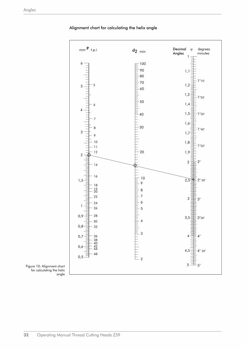
8.3. Calculating the helix angle
Normally, it is not necessary to know the helix angle of the thread to be cut, since the threads are listed in the chaser holder table with their corresponding holders.In special cases, however, not listed in the chaser holder table, the helix angle can ea-sily be calculated by the alignment chart on page 32. It is essential to use the effective rather than the major diameter of the concerning thread in the calculation:
d2 =
d2 = effective diameterd = major diameterd3 = minor diameter
The helix angle ϕ is calculated according to the expression:
tg ϕ =
»P« is the pitch of the thread in millimetres and»d2« is the effective diameter
The left-hand scale of the alignment chart on page 32 represents values of »P«, the centre scale represents values of »d2« and the right-hand scale represents the pitch angle »ϕ«. The latter value is calibrated in decimal form on the left-hand side of the scale and in degrees and minutes of arc on the right-hand side of the scale.
The pitch of the desired thread is found on the »P«-scale and the effective diameter is found on the »d2«-scale. The straight line connecting these points will pass through the »ϕ«-scale and give the desired helix angle.
In the example shown the helix angle for an M16 metric thread is calculated. The effective diameter is equal to:
d2 = = 14.701 mm
The flank diameter is also equal to 14.701 mm.The pitch »P« is equal to 2 mm. The straight line »P-d2« provides the helix angle ϕ of 2.49° or 2° 29‘.In most cases the effective diameter is almost identical with the flank diameter; the latter may therefore be used in these calculations.
da + dk2
16 + 13.4022
d + d3
2
Pπ • d2
32 Operating Manual Thread Cutting Heads Z39
Angles
Alignment chart for calculating the helix angle
Figure 10: Alignment chart for calculating the helix
angle

Operating Manual Thread Cutting Heads Z39 33
Illustrated parts list and accessories
9. Illustrated parts list and accessories
9.1. Individual parts of thread cutting head Z 39 (Product No. 73800300)
Item Quantity Order No. Designation
1 1 71050000 head body
2 1 71060300 eccentric ring
3 2 71060400 insert plates
4 1 71060200 guide ring
5 4 02016214 adjusting screw
6 1 71050500 screw nut
7 1 71050400 collar bush
8 1 02016054 cheese-head screw
9 1 70546000 stop bolt
10 1 03310107 pressure spring
11 4 02030106 headless screw
12 4 71050600 pressure bush
13 4 03310134 pressure spring
14 1 71050300 sliding key
15 2 02020159 counter sunk screw
16 2 71050800 cheese-head screw
29 1 70569900 clamping ring
Accessories Head
26 1 02677007 hexagon socket
27 1 78002100 taper key with screw driver
28 1 03697203 short allen key with screw driver
18 4 chaser holder (on request)
17 4 02121307 pressure pin
20 8 03011701 clamping screw
21 4 clamping plate (on request)
22 4 02020107 counter sunk screw
23 4 70562000 shoe
24 4 adjusting screw with stop (on request)
34 4 shim (on request)
19 4 chaser (on request)

34 Operating Manual Thread Cutting Heads Z39
Illustrated parts list and accessories
Carrier ring complete (Product No. 70569800)
30 1 71052400 carrier ring
31 2 71196300 carrier jaw
32 2 71052600 bolt
33 2 02044206 threaded pin
Setting device complete (Product No. 73419000)
E21 1 73419100 setting bearing
E21.1 1 02035508 knurled screw
E21.2 1 03240195 clamping lever with external thread
1 73577400 pressure piece
E22 1 73418600 dial gauge holder
E23 1 70536500 stop
E24 1 02035416 knurled screw
E25 1 70536400 setting gauge
E26 1 06525003 dial gauge

Operating Manual Thread Cutting Heads Z39 35
Illustrated parts list and accessories

36 Operating Manual Thread Cutting Heads Z39
Special detent
10. Special detent
Single parts for the die head Z 39-2 with special detent
Item Quantity Order No. Designation35 1 738018 toothed segment (compl. set 10 pieces)36 1 735600 holding piece37 2 cheese head

ImprintThis operating manual is a publication made by WAGNER® Werkzeugsysteme Müller GmbH. Information in this catalog is current as of publication date and subject to change.
All rights reserved.
Date: 8|2016
WAGNER® Werkzeugsysteme Müller GmbHGutenbergstraße 4/1D-72124 Pliezhausen
fon: +49(0) 71 27/ 97 33-00fax: +49(0) 71 27/ 97 33-90
email: [email protected]: www.wagner-werkzeug.de