operating manual - universidade estadual de londrina · pulverisette 6 fritsch planetary mono mill...
TRANSCRIPT

PULVERISETTE 6
FRITSCH PLANETARY MONO MILL
Operating Manual Translation of the original

PULVERISETTE 6

Edition 03/2005 Index 006
PULVERISETTE 6
Fritsch GmbH
Manufacturers of Laboratory Instruments
Industriestraße 8
D - 55743 Idar-Oberstein
Phone: +49 (0)6784/ 70-0
Fax: +49 (0)6784/ 70-11
E-Mail: [email protected]
Internet: http://www.fritsch.de
Fritsch GmbH, has been certified by the TÜV-Zertifizierungsgemeinschaft e.V..
It was verified through an audit that Fritsch GmbH satisfies the requirements of DIN EN ISO 9001:2008.
The enclosed declaration of conformity calls the directives
which the „PULVERISETTE 6“ corresponds to.
This permitts us to mark the instrument with the CE-Sign.
Instrument number 06.2000.00
Applies as of serial number 1336
Page 1
PULVERISETTE 6
Table of contents page
1 General Information / Introduction ..................................................... 3
1.1 Notes about Operating Instructions ............................................................... 3
1.2 Explanations of the signs at the instrument and in the operating instructions .................................................................................................... 4
1.3 Short Description of the Machine .................................................................. 5
1.3.1 Applications ......................................................................................................... 5 1.3.2 Method of Operation ............................................................................................ 5 1.3.3 Drive Motor and Speed Control ........................................................................... 5
1.4 Technical Data .............................................................................................. 6
2 Operating Safety.................................................................................. 7
2.1 General Safety Instructions ........................................................................... 7
2.2 Operators ...................................................................................................... 8
2.3 Protective Devices ........................................................................................ 8
2.4 Danger Points ............................................................................................... 9
2.5 Electrical Safety ............................................................................................ 9
2.5.1 General ................................................................................................................ 9
2.5.2 Protection against Restarting ............................................................................... 9 2.5.3 Overload Protection (see 8 Troubleshooting Checklist) ....................................... 9
2.5.4 Unbalance Detection (see 8 Troubleshooting Checklist) ..................................... 9
3 Installation ......................................................................................... 10
3.1 Unpacking ................................................................................................... 10
3.2 Transport ..................................................................................................... 10
3.3 Erection ....................................................................................................... 10
3.4 Ambience conditions ................................................................................... 11
3.5 Electrical Connection .................................................................................. 11
3.6 Adaptation to Mains Supply Voltage, Changing Timer and Unbalance Detection in setup mode ............................................................................. 12
3.7 Switching On for the First Time / Test for Correct Functioning ................... 13
4 Working with the Planetary Monomill .............................................. 14
4.1 Choice of Grinding Bowls and Grinding Balls ............................................. 15
4.1.1 Size of the Grinding Balls .................................................................................. 16
4.1.2 Number of Balls per Grinding Bowl .................................................................... 16
4.1.3 Calculated Ball Weight ...................................................................................... 17
4.2 Filling the Grinding Bowl ............................................................................. 17
4.3 Influencing Quantities During Grinding ....................................................... 18
4.3.1 Dry Grinding ....................................................................................................... 18 4.3.2 Wet Grinding (Grinding in Suspension) ............................................................. 18
4.4 Clamping the Grinding Bowls ...................................................................... 19
4.4.1 Clamping with the "Safe Lock" Holder ............................................................... 19 4.4.2 Clamping the 80 ml grinding bowl ...................................................................... 19
4.4.3 Clamping with Additional Tensioning System .................................................... 20
4.5 Mass Balance .............................................................................................. 21
4.6 Grinding Time.............................................................................................. 21
4.7 Control Panel .............................................................................................. 22
4.7.1 Setting the Speed .............................................................................................. 22 4.7.2 Setting the Running Time .................................................................................. 22

Page 2
PULVERISETTE 6
4.7.3 Reversing Operation .......................................................................................... 22 4.7.4 Repetition of the Grinding / Break Cycles .......................................................... 22
4.8 Performing a Grinding Operation ................................................................ 23
4.9 Cooling the Grinding Bowls ......................................................................... 23
4.10 Standby ....................................................................................................... 23
4.11 Grinding under protective gas with gas lid .................................................. 24
4.12 GTM System ............................................................................................... 26
5 Cleaning ............................................................................................. 27
5.1 Grinding accessories ................................................................................... 27
5.2 Mill ............................................................................................................... 27
6 Maintenance ...................................................................................... 28
7 Warranty............................................................................................. 29
8 Troubleshooting Checklist ............................................................... 30
9 Examples of Comminution Tasks .................................................... 31
10 Disclaimer .......................................................................................... 33
Page 3
PULVERISETTE 6
1 General Information / Introduction
1.1 Notes about Operating Instructions
The copyright to these technical documents is the property of Fritsch GmbH, Manufacturers of Laboratory Instruments.
These operating instructions are not to be reprinted or copied without the express approval of Fritsch GmbH.
Please study these instructions carefully before operation.
All operators must be familiar with the contents of the operating instructions.
Please observe all notes concerning your safety.
The mill was designed with the user's safety in mind, however inherent risks cannot be excluded. Follow the advices in these instructions to avoid risks to users. The symbols in the right hand margin highlight the risks described in the text.
Symbols are also to be found on the instrument warning users of possible risks. Warning symbols are surrounded by a triangle.
These operating instructions do not constitute a complete technical description. They describe only the details required for safe operation and maintenance for usage under normal conditions.
Attention!
observe operating
instructions
Page 4
PULVERISETTE 6
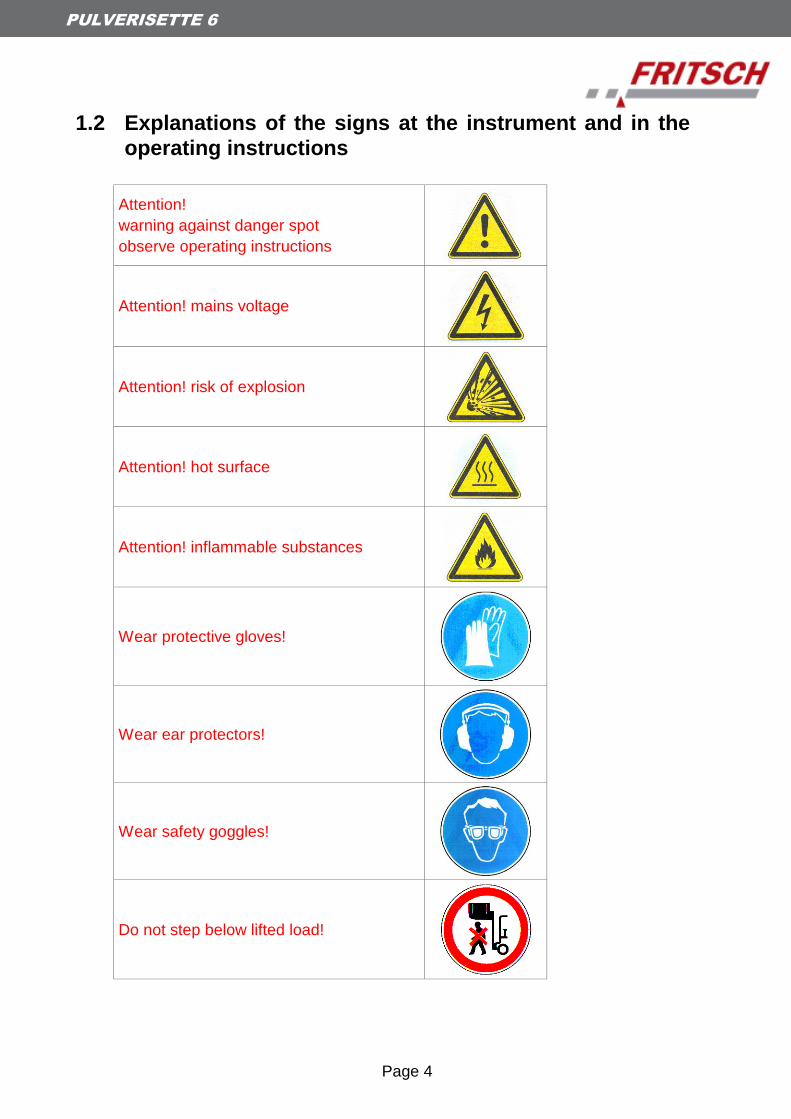
1.2 Explanations of the signs at the instrument and in the
operating instructions
Attention!
warning against danger spot
observe operating instructions
Attention! mains voltage
Attention! risk of explosion
Attention! hot surface
Attention! inflammable substances
Wear protective gloves!
Wear ear protectors!
Wear safety goggles!
Do not step below lifted load!
Page 5
PULVERISETTE 6
1.3 Short Description of the Machine
1.3.1 Applications
The "pulverisette 6" planetary monomill is universally applicable for quick dry or wet grinding of inorganic and organic samples for analysis, quality control, materials testing and mechanical alloying.
In synthesis, the planetary monomill can be used for mixing and homogenisation of dry samples, of emulsions and of pastes.
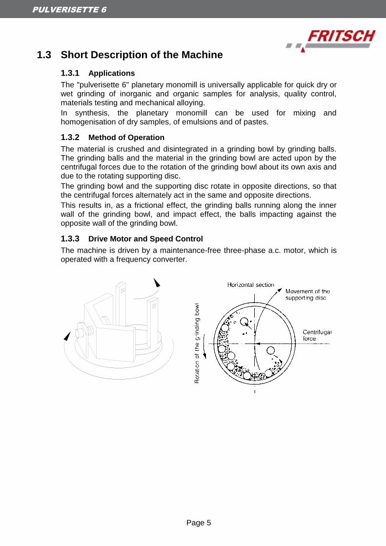
1.3.2 Method of Operation
The material is crushed and disintegrated in a grinding bowl by grinding balls. The grinding balls and the material in the grinding bowl are acted upon by the centrifugal forces due to the rotation of the grinding bowl about its own axis and due to the rotating supporting disc.
The grinding bowl and the supporting disc rotate in opposite directions, so that the centrifugal forces alternately act in the same and opposite directions.
This results in, as a frictional effect, the grinding balls running along the inner wall of the grinding bowl, and impact effect, the balls impacting against the opposite wall of the grinding bowl.
1.3.3 Drive Motor and Speed Control
The machine is driven by a maintenance-free three-phase a.c. motor, which is operated with a frequency converter.
Page 6
PULVERISETTE 6
1.4 Technical Data
Dimensions and Weight
Dimensions: 500 x 370 x 530 mm (height x width x depth)
Weight: approx. 67 kg (net), approx. 87 kg (gross)
Operating Noise
The noise level can be as high as approx. 85dB (A). The value fluctuates greatly depending on the speed, the material being ground and on the type of grinding bowl and grinding balls.
Voltage
The machine can be operated in two voltage ranges:
Single-phase alternating voltage 100-120V ± 10% and
Single-phase alternating voltage 200-240V ± 10%.
(see also section Adaptation to Mains Supply)
Transient overvoltages according to overvoltage category II allowed.
Current Input
The maximum current input is:
voltage range current input
100 - 120 V maximum 12 A
200 – 240 V maximum 7 A
Power consumption
The maximum power consumption is approx. 1,1kW.
Electrical Fuses
Fuse unit at the rear of the machine: 2 x 10 A T
Miniature fuse 10 A T in the frequency converter (remove housing)
Material
Maximum feed size approx. 10 mm
Maximum feed quantity 225 ml
Final fineness
Dry grinding down to d50 < 20 µm (depending on material)
Wet grinding down to d50 < 1 µm (depending on material)
Page 7
PULVERISETTE 6
2 Operating Safety
2.1 General Safety Instructions
Read the operating instructions carefully before use.
The instrument can only to be used for the purpose described in Chapter 1.3.1 Applications.
Use only original accessories and original spare parts. Failure to do so may call into question the performance of the instrument.
Do not use damaged accessories.
The operators must be familiar with the contents of the operating instructions.
To this end, for example, the operating instructions must with the instrument.
Do not remove labels.
Protective devices must not be made unserviceable or removed.
Unauthorized modification of the instrument or any part thereof will result in the loss of the conformity to European directives which is asserted by Fritsch and the warranty.
Wear protective gloves! Grinding bowls may be very hot after grinding.
Wear safety glasses Wet grinding may cause high pressure in the grinding bowl- Danger of squirting!
Wear ear protectors - noise level up to 85dB(A).
Don’t run the instrument several hours without cooling phases - Danger of overheating.
Behaviour at all times must be such as to strictly preclude any accidents.
Furthermore, the MAC values at place of work specified in the pertinent safety regulations must be adhered to. Where applicable, ventilation must be provided or the instrument must be operated under an exhaust hood.
When oxidizable materials such as metals, organic materials, wood, coal, plastic, etc. are ground or sieved, the risk of spontaneous ignition (dust explosion) exists whenever the fine particles exceed a specific percentage. While such materials are being ground, it is therefore necessary to take special safety precautions (e.g. wet grinding) and the work must be supervised by a specialist.
The instrument is not explosion-proof and is unsuitable to grind or sieve materials which are explosive, combustible or promote combustion.
Do not allow the planetary monomill to run unsupervised. Due to the vibrations, under certain operating conditions, the machine may creep along the surface on which it is located or mounted.
Observe operating
instructions!!
Wear protective gloves!
Wear safety goggles!
Wear ear protectors!
Attention! risk of
explosion
Page 8
PULVERISETTE 6
2.2 Operators
No one other than authorized persons should operate the instrument and it must be serviced and repaired by trained specialists.
No one suffering from medical problems or under the influence of medications, drugs, alcohol or overtiredness should be permitted to operate the instrument.
2.3 Protective Devices
Protective devices should be used for the intended purpose and must not
be made unserviceable or removed.
All protective devices should be regularly checked for completeness and
to ensure that they are functioning correctly. See section Maintenance.
The hood must be closed when the machine is started up.
The hood is locked:
when the machine is disconnected from the mains supply
during operation
The hood can be opened only when the drive of the mill has come to a
standstill.
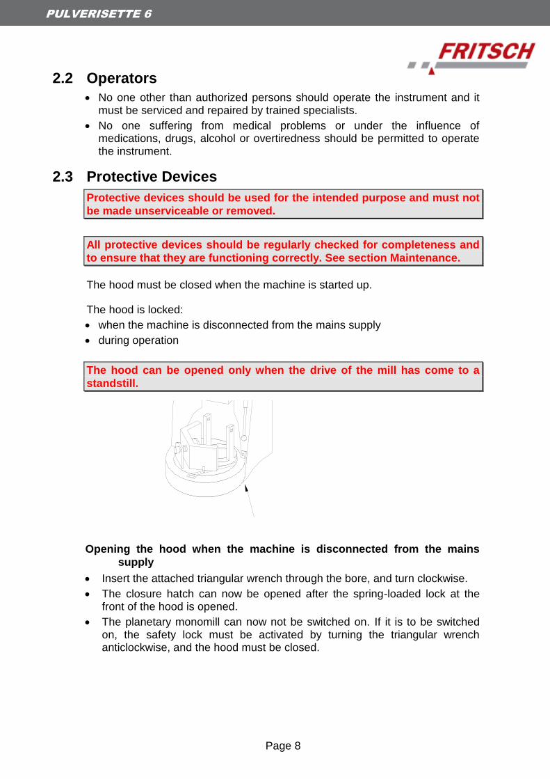
Opening the hood when the machine is disconnected from the mains
supply
Insert the attached triangular wrench through the bore, and turn clockwise.
The closure hatch can now be opened after the spring-loaded lock at the front of the hood is opened.
The planetary monomill can now not be switched on. If it is to be switched on, the safety lock must be activated by turning the triangular wrench anticlockwise, and the hood must be closed.

Page 9
PULVERISETTE 6
2.4 Danger Points
Danger of crushing when the hood is being closed.
Danger of crushing at the grinding bowl holder.
Danger of crushing at the unbalance compensation.
2.5 Electrical Safety
2.5.1 General
The main switch disconnects the machine from the mains supply at two poles.
Switch off the main switch if the planetary monomill is to be inoperative for an extended period (e.g. over night).
2.5.2 Protection against Restarting
In the event of a mains failure during operation or after switching-off with the main switch, the hood will remain locked. When the mains voltage is restored, the lock of the hood will open. For safety reasons, however, the planetary monomill will not start again.
2.5.3 Overload Protection (see 8 Troubleshooting Checklist)
In the event of overloading, the speed of the machine will be reduced. This is indicated by the REDUCED SPEED light beeing illuminated.
If the drive motor overheats, the machine will switch off.
If the drive is obstructed, the machine will switch off.
2.5.4 Unbalance Detection (see 8 Troubleshooting Checklist)
In the event of an excessive unbalance, the machine will switch off.
Attention!
Page 10
PULVERISETTE 6
3 Installation
3.1 Unpacking
Open the bandages with which the hood is fastened on the transport pallet. The hood is a wooden box placed over the transport pallet.
Lift the hood off the transport pallet.
The cellular parts can be removed now or during the installation. To ease this removal you can break the performated segments.
Check that the items supplied correspond to your order. Grinding bowls of hardened steel may exhibit surface indentations caused by the manufacturing process. These do not influence the grinding or the grinding result and generally disappear after the first grinding. When present, these surface indentations lie within the permissible manufacturing tolerance ranges. Accordingly, complaints regarding such grinding bowls cannot be accepted.
Please store the transport packing carefully to use it again in case of an eventual return of the instrument. Fritsch GmbH does not bear the risk of damages depending on improper packings (non-Fritsch packings).
3.2 Transport
Transport the planetary monomill on the transport pallet with a fork lift truck or a hand fork lift truck.
To carry the machine, grip it below the edge of the housing.
Carrying the machine will require at least two persons.
3.3 Erection
Lift the planetary monomill off the transport pallet.
Lifting the machine down will require at least two persons.
If the cellular parts have not yet been removed, this can be done now. See chapter 3.1 Unpacking.
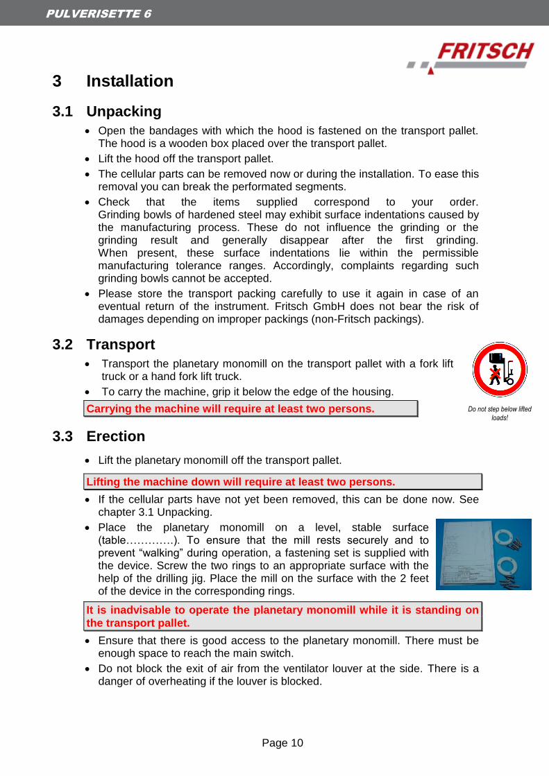
Place the planetary monomill on a level, stable surface (table………….). To ensure that the mill rests securely and to prevent “walking” during operation, a fastening set is supplied with the device. Screw the two rings to an appropriate surface with the help of the drilling jig. Place the mill on the surface with the 2 feet of the device in the corresponding rings.
It is inadvisable to operate the planetary monomill while it is standing on
the transport pallet.
Ensure that there is good access to the planetary monomill. There must be enough space to reach the main switch.
Do not block the exit of air from the ventilator louver at the side. There is a danger of overheating if the louver is blocked.
Do not step below lifted
loads!
Page 11
PULVERISETTE 6
3.4 Ambience conditions
Use the instrument only inside.
The air must not contain any electrical conductive dust.
The ambient temperature must be between 5 and 40°C.
Height up to 2000m M.S.L.
Maximum relative humidity of air 80% temperature up to 31C, linear
decreasing down to 50% relative humidity of air at 40C4
Contamination level 2 (IEC 664)
3.5 Electrical Connection
Before making the connection, compare the voltage and current values shown on the nameplate with the values of the mains supply to which the instrument is to be connected.
Single-phase alternating voltage with protective conductor (see section 1.4).
Caution
Non-observance of the values on the type plate may damage electrical as well as mechanical components.
Page 12
PULVERISETTE 6
3.6 Adaptation to Mains Supply Voltage, Changing Timer
and Unbalance Detection in setup mode
The voltage range of the machine should be switched over only by
specialist staff.
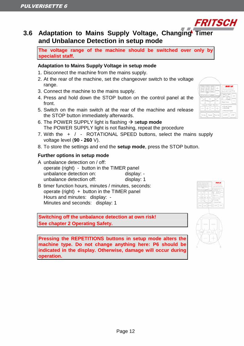
Adaptation to Mains Supply Voltage in setup mode
1. Disconnect the machine from the mains supply.
2. At the rear of the machine, set the changeover switch to the voltage range.
3. Connect the machine to the mains supply.
4. Press and hold down the STOP button on the control panel at the front.
5. Switch on the main switch at the rear of the machine and release the STOP button immediately afterwards.
6. The POWER SUPPLY light is flashing setup mode The POWER SUPPLY light is not flashing, repeat the procedure
7. With the + / - ROTATIONAL SPEED buttons, select the mains supply
voltage level (90 - 260 V).
8. To store the settings and end the setup mode, press the STOP button.
Further options in setup mode
A unbalance detection on / off: operate (right) - button in the TIMER panel unbalance detection on: display: - unbalance detection off: display: 1
B timer function hours, minutes / minutes, seconds: operate (right) + button in the TIMER panel Hours and minutes: display: - Minutes and seconds: display: 1
Switching off the unbalance detection at own risk!
See chapter 2 Operating Safety.
Pressing the REPETITIONS buttons in setup mode alters the
machine type. Do not change anything here: P6 should be
indicated in the display. Otherwise, damage will occur during
operation.

Page 13
PULVERISETTE 6
3.7 Switching On for the First Time / Test for Correct
Functioning
Switch on the machine only when all the work described in section 3 on Installation has been done.
Switching On
1. Connect the machine to the mains supply.
2. Switch on the machine with the main switch at the rear.
3. The POWER SUPPLY display will come on.
4. Open the hood.
5. If the grinding bowl holder or any wood are present, take them out. There should be nothing in the grinding bowl holder.
6. Move the counterweight in fully.
7. Close the hood.
8. Set the speed to 100 on the control panel.
9. Press START on the control panel.
10. The hood will be locked and the mill will run at the preselected speed.
Perform this test at a speed of not more than 100 rpm, and make sure to
move the counterweight in fully, as an excessively large unbalance will
otherwise occur.
Switching Off
Press STOP on the control panel.
After a short period (after the mill has come to a standstill), the hood is unlocked and can be opened.
Page 14
PULVERISETTE 6
4 Working with the Planetary Monomill
Warning!!!
Before starting the machine, ensure that the grinding bowl is correctly braced and there are no loose parts inside the device. There is a risk that loose grinding bowls or parts will be thrown out. If this instruction is not observed, no guarantee or claims will be accepted for damages to the device or injuries to persons.
Caution!!!
The grinding tools are subject to normal wear. Prior to each comminution the thickness of the grinding bowl wall is to be inspected. With severe wear the grinding bowl is to be changed. If not, the possibility exists that the grinding ball due to high centrifugal forces which occur during the grinding may strike through the grinding bowl wall, damaging the mill. We don’t honour the warranty or accept complaints for instrument damage or personal injuries occurring when disregarding the above information.
NOTE
During milling, high temperatures can build up in the grinding
bowl.
In encased grinding bowls, the inserts are glued into the
casing with a two-component construction adhesive.
The adhesive is temperature-resistant up to approx. 140°C.
Above 140°C, the adhesive becomes liquefied and collects
below the insert in the casing. When the adhesive cools
down, it solidifies again and presses the casing upward. As a
result, the insert could get damaged. This always makes the
grinding bowl unusable.
At temperatures above 200°C, the adhesive is ruined. The
same applies for encased grinding bowl lids.
Page 15
PULVERISETTE 6
4.1 Choice of Grinding Bowls and Grinding Balls
Caution!!!
No warranty or claims shall be accepted in case of damages caused on account of using grinding bowls and grinding balls that are not original accessories of the appliance.
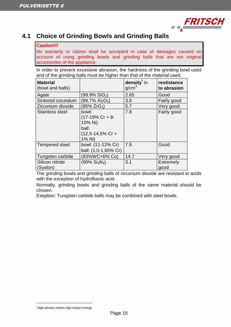
In order to prevent excessive abrasion, the hardness of the grinding bowl used and of the grinding balls must be higher than that of the material used.
Material (bowl and balls)
density* in
g/cm3
restistance
to abrasion
Agate (99.9% SiO2) 2.65 Good
Sintered corundum (99.7% Al2O3) 3.8 Fairly good
Zirconium dioxide (95% ZrO2) 5.7 Very good
Stainless steel bowl: (17-19% Cr + 8-10% Ni)
ball: (12,5-14,5% Cr + 1% Ni)
7.8 Fairly good
Tempered steel bowl: (11-12% Cr)
ball: (1,0-1,65% Cr)
7.9 Good
Tungsten carbide (93%WC+6% Co) 14.7 Very good
Silicon nitride (Syalon)
(90% Si3N4) 3.1 Extremely good
The grinding bowls and grinding balls of zirconium dioxide are resistant to acids with the exception of hydrofluoric acid.
Normally, grinding bowls and grinding balls of the same material should be chosen. Exeption: Tungsten carbide balls may be combined with steel bowls.
*High density means high impact energy

Page 16
PULVERISETTE 6
4.1.1 Size of the Grinding Balls
Type of feed material Ball diameter
Hard samples feed particle size <10 mm
30 mm or 40 mm
Medium piece size (<5 mm) 20 mm
Fine material (0.5 mm) 10 mm or 5 mm
Homogenisation of dry or liquid samples
10 mm
Homogenisation of viscous samples 20 mm
This are just clues: the size of the grinding bowls and grinding balls
should be determined experimentally if necessary.
Attention:
Mixing balls with different diameters is not recommended.
(If different ball diameters are used there is the danger of higher abrasion
of the balls!)
4.1.2 Number of Balls per Grinding Bowl
A larger number of balls reduces the grinding time, and the grinding result will lie within a narrower grain band width.
Ball Ø
(mm)
Grinding bowl volume (ml)
80
250
500
5 Number of balls
(piece) 250 - 300
1200 - 1300
2000 - 2500
10 Number of balls
(piece) 30 - 35 50 - 150 100 - 250
15 Number of balls
(piece) 10 45 - 50 70 - 100
20 Number of balls
(piece) 5 15 - 20 25 - 35
30 Number of balls
(piece) 5 - 6 10
40 Number of balls
(piece) 4
These values are just clues: the number of balls should be determined
experimentally if necessary.
While using balls with diameter Ø 30 and Ø 40 mm please look after the
unit permanently, because the vibrations could cause the machine to
move around.
Page 17
PULVERISETTE 6
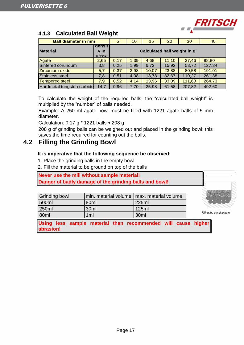
4.1.3 Calculated Ball Weight
5 10 15 20 30 40
Material
densit
y in
g/cm³Agate 2,65 0,17 1,39 4,68 11,10 37,46 88,80
Sintered corundum 3,8 0,25 1,99 6,72 15,92 53,72 127,34
Zirconium oxide 5,7 0,37 2,98 10,07 23,88 80,58 191,01
Stainless steel 7,8 0,51 4,08 13,78 32,67 110,27 261,38
Tempered steel 7,9 0,52 4,14 13,96 33,09 111,68 264,73
Hardmetal tungsten carbide 14,7 0,96 7,70 25,98 61,58 207,82 492,60
Ball diameter in mm
Calculated ball weight in g
To calculate the weight of the required balls, the “calculated ball weight” is multiplied by the “number” of balls needed.
Example: A 250 ml agate bowl must be filled with 1221 agate balls of 5 mm diameter.
Calculation: 0.17 g * 1221 balls ≈ 208 g
208 g of grinding balls can be weighed out and placed in the grinding bowl; this saves the time required for counting out the balls.
4.2 Filling the Grinding Bowl
It is imperative that the following sequence be observed:
1. Place the grinding balls in the empty bowl.
2. Fill the material to be ground on top of the balls
Never use the mill without sample material!
Danger of badly damage of the grinding balls and bowl!
Grinding bowl min. material volume max. material volume
500ml 80ml 225ml
250ml 30ml 125ml
80ml 1ml 30ml
Using less sample material than recommended will cause higher
abrasion!
Filling the grinding bowl
Page 18
PULVERISETTE 6
4.3 Influencing Quantities During Grinding
Running time (grinding time)
A longer grinding time will increase the fine fraction.
Speed
A higher speed will reduce the grinding time and increase the fine fraction.
Reversing operation (regular reversal of the direction of rotation)
useful for mechanical alloying
improves homogenizing of the material
Number and size of the balls
Pregrinding coarse, hard material with large balls: small fine fraction.
Use of many small balls will increase the fine fraction if the running time is increased.
Mass of the balls (type of material)
A higher mass (density) of the grinding balls will accelerate the grinding.
(see the table in section 4.1 on Choice of Grinding Bowls and Grinding Balls)
4.3.1 Dry Grinding Below a particle size of approx. 20 µm, surface forces predominate and the material will start to "stick".
Further dry grinding can be achieved if surface-active substances are added to the material.
Examples (maximum quantity to be added in % by mass)
Stearic acid 2-3%
Aerosil (microdispersed silicic acid) 0.5-2%
Silica sand ~ 2%
Glass powder ~ 2%
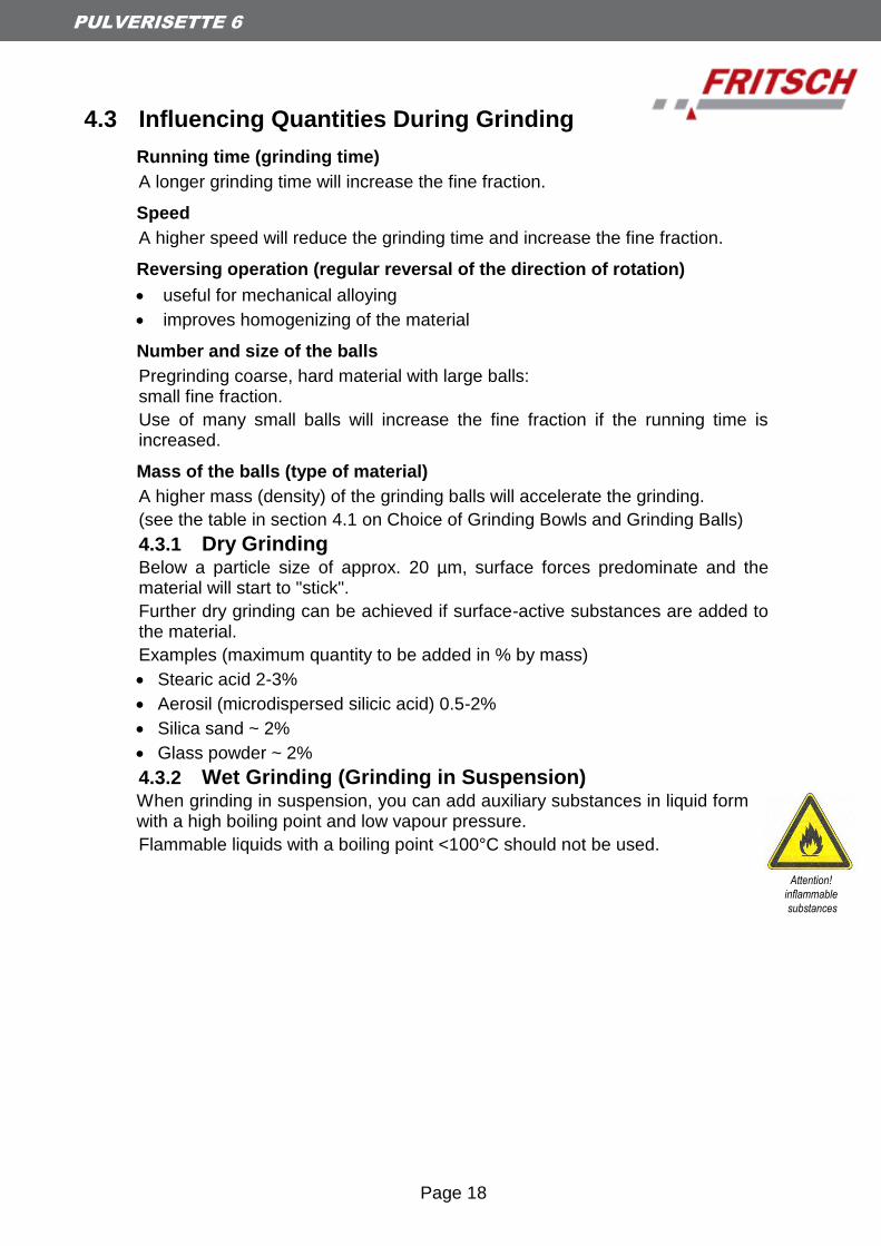
4.3.2 Wet Grinding (Grinding in Suspension) When grinding in suspension, you can add auxiliary substances in liquid form with a high boiling point and low vapour pressure.
Flammable liquids with a boiling point <100°C should not be used.
Attention!
inflammable
substances

Page 19
PULVERISETTE 6
4.4 Clamping the Grinding Bowls
4.4.1 Clamping with the "Safe Lock" Holder
The following tests should be performed before the grinding bowls are clamped in the machine before each grinding operation:
Is the black rubber disk inserted in the bowl holder? Rough side up! (Check before first run)
Check the rubber disc in the bowl holder for damage. Replace rubber discs that are flattened.
The flat Teflon seal (for sealing between the lid and the bowl) must not be damaged or dirty. Replace severely deformed flat Teflon seals.
The surfaces of the lid and of the bowl on which the flat Teflon seal rests must be clean.
Check the rubber disc at the safelock for damage. Replace rubber discs that are flattened and project laterally beyond the pressure piece.
Clamping
After a few minutes of grinding, and in the cooling phases, check that the clamping is secure.
4.4.2 Clamping the 80 ml grinding bowl
Either use the 80 ml with the reducing piece fitted (order no. 90.1120.09) or
Use two 80 ml grinding bowls, one on top of the other.
Safe lock 90.0900.00
90.1380.00
tighten screw
Page 20
PULVERISETTE 6
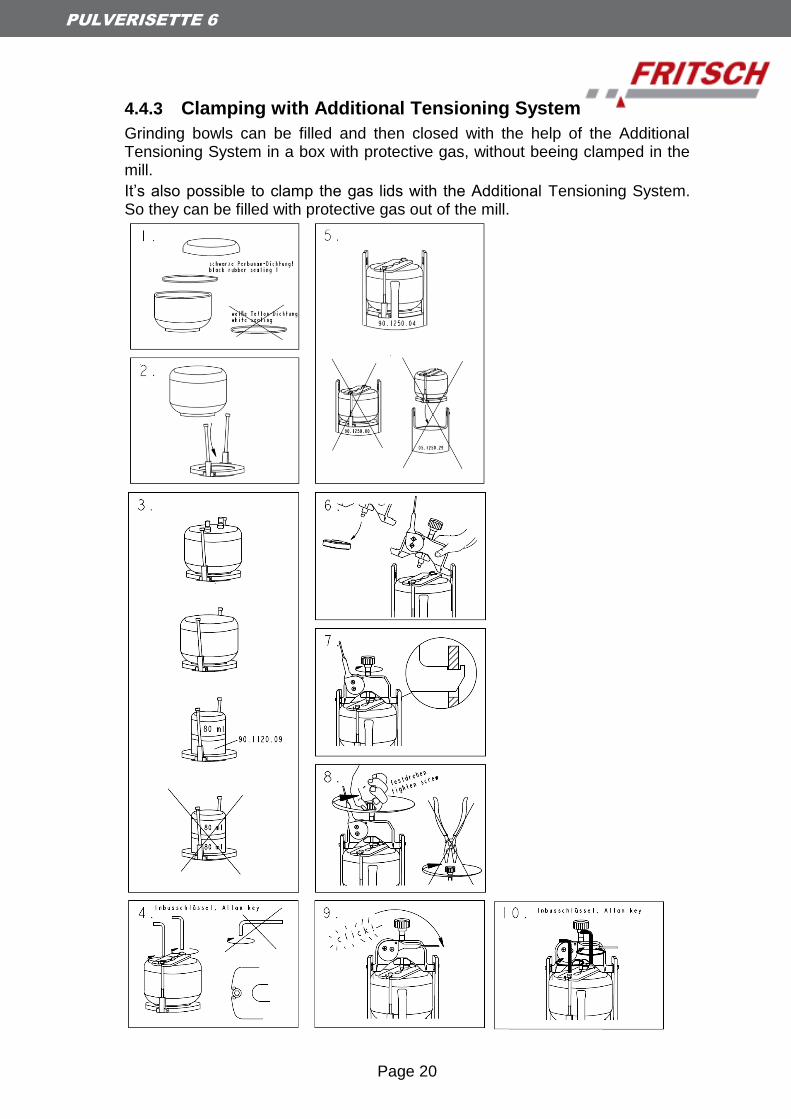
4.4.3 Clamping with Additional Tensioning System
Grinding bowls can be filled and then closed with the help of the Additional Tensioning System in a box with protective gas, without beeing clamped in the mill.
It’s also possible to clamp the gas lids with the Additional Tensioning System. So they can be filled with protective gas out of the mill.
Page 21
PULVERISETTE 6
4.5 Mass Balance
In order to compensate for the unbalance, the counterweight should be positioned in accordance with the scale (right).
The weight indicated on the scale is the weight of the filled grinding bowl with lid.
If heavy bowls are used and/or high speed is set an adjustment of
the mass balance may be necessary.
CAUTION
Additional weights like „GTM“ and “additional tensioning system”
must also be balanced.
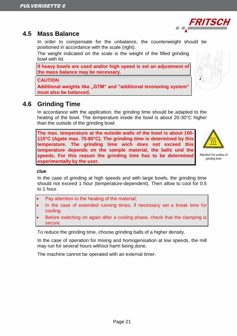
4.6 Grinding Time
In accordance with the application, the grinding time should be adapted to the heating of the bowl. The temperature inside the bowl is about 20-30°C higher than the outside of the grinding bowl.
The max. temperature at the outside walls of the bowl is about 100-
110°C (Agate max. 70-80°C). The grinding time is determined by this
temperature. The grinding time wich does not exceed this
temperature depends on the sample material, the balls und the
speeds. For this reason the grinding time has to be determined
experimentally by the user.
clue
In the case of grinding at high speeds and with large bowls, the grinding time should not exceed 1 hour (temperature-dependent). Then allow to cool for 0.5 to 1 hour.
Pay attention to the heating of the material;
In the case of extended running times, if necessary set a break time for cooling.
Before switching on again after a cooling phase, check that the clamping is secure.
To reduce the grinding time, choose grinding balls of a higher density.
In the case of operation for mixing and homogenisation at low speeds, the mill may run for several hours without harm being done.
The machine cannot be operated with an external timer.
Attention! hot surface of
grinding bowl
Page 22
PULVERISETTE 6
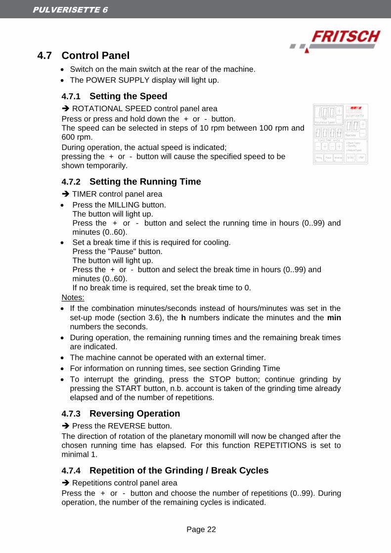
4.7 Control Panel
Switch on the main switch at the rear of the machine.
The POWER SUPPLY display will light up.
4.7.1 Setting the Speed
ROTATIONAL SPEED control panel area
Press or press and hold down the + or - button. The speed can be selected in steps of 10 rpm between 100 rpm and 600 rpm.
During operation, the actual speed is indicated; pressing the + or - button will cause the specified speed to be shown temporarily.
4.7.2 Setting the Running Time
TIMER control panel area
Press the MILLING button. The button will light up. Press the + or - button and select the running time in hours (0..99) and minutes (0..60).
Set a break time if this is required for cooling. Press the "Pause" button. The button will light up. Press the + or - button and select the break time in hours (0..99) and minutes (0..60). If no break time is required, set the break time to 0.
Notes:
If the combination minutes/seconds instead of hours/minutes was set in the
set-up mode (section 3.6), the h numbers indicate the minutes and the min numbers the seconds.
During operation, the remaining running times and the remaining break times are indicated.
The machine cannot be operated with an external timer.
For information on running times, see section Grinding Time
To interrupt the grinding, press the STOP button; continue grinding by pressing the START button, n.b. account is taken of the grinding time already elapsed and of the number of repetitions.
4.7.3 Reversing Operation
Press the REVERSE button.
The direction of rotation of the planetary monomill will now be changed after the chosen running time has elapsed. For this function REPETITIONS is set to minimal 1.
4.7.4 Repetition of the Grinding / Break Cycles
Repetitions control panel area
Press the + or - button and choose the number of repetitions (0..99). During operation, the number of the remaining cycles is indicated.

Page 23
PULVERISETTE 6
4.8 Performing a Grinding Operation
After everything has been set up as described in section 4 on Working with the Planetary Monomill, close the hood.
Press the START button on the control panel.
The hood will be locked and the planetary monomill will run.
The planetary monomill will rotate at the speed set (set speed) – if the load is too great, e.g. if the grinding bowl is too large, the machine will be run at a lower speed (actual speed) so as to prevent overloading.
If the planetary monomill does not start, see the Troubleshooting Checklist in section 8.
Overloading
In the event of overloading of the planetary monomill, the speed will be reduced and the REDUCED SPEED light will shine.
If it is overloaded for a prolonged period, the mill will switch off; see the Troubleshooting Checklist in section 8.
Miscellaneous
During operation, the hood will remain locked even during the breaks, and the fan will run.
Switching Off
Press STOP on the control panel.
When the drive has come to a standstill, the hood is unlocked and can be opened.
Switch off the main switch at the rear of the machine if the machine is to be inoperative for an extended period.
4.9 Cooling the Grinding Bowls
with the hood open or
at the programmed break times with the hood closed (locked) and the ventilator running.
4.10 Standby
After one hour, if the mill is not being operated and the hood is open, the mill will switch to the energy-saving standby mode. The STAND BY light will come on.
The standby function will not be activated when the hood is closed.
Attention! hot surface of
grinding bowl
Page 24
PULVERISETTE 6
4.11 Grinding under protective gas with gas lid
Important! compensate any unbalance
see chapter 4.5 Mass Balance
For grinding under protective gas, the same conditions apply for the selection of the grinding set and grinding balls.
Two valves are screwed onto the gas lid. Before switching on the mill, you can introduce protective gas, e.g. nitrogen, through these.
A Viton flat seal is used instead of the Teflon flat seal.
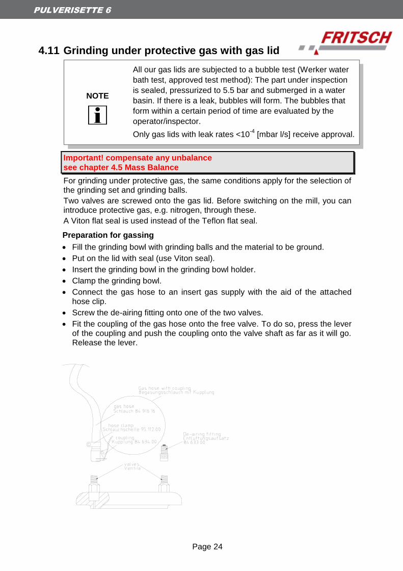
Preparation for gassing
Fill the grinding bowl with grinding balls and the material to be ground.
Put on the lid with seal (use Viton seal).
Insert the grinding bowl in the grinding bowl holder.
Clamp the grinding bowl.
Connect the gas hose to an insert gas supply with the aid of the attached hose clip.
Screw the de-airing fitting onto one of the two valves.
Fit the coupling of the gas hose onto the free valve. To do so, press the lever of the coupling and push the coupling onto the valve shaft as far as it will go. Release the lever.
NOTE
All our gas lids are subjected to a bubble test (Werker water
bath test, approved test method): The part under inspection
is sealed, pressurized to 5.5 bar and submerged in a water
basin. If there is a leak, bubbles will form. The bubbles that
form within a certain period of time are evaluated by the
operator/inspector.
Only gas lids with leak rates <10-4
[mbar l/s] receive approval.

Page 25
PULVERISETTE 6
Gassing
Slowly open the inert gas feed.
Press on the top of the de-airing fitting so that the air can escape from the grinding bowl.
The inert gas will now flush the air out of the grinding bowl.
The flushing period must be determined experimentally; the flushing period is dependent on, inter alia, the grinding bowl size, the filling and the gas feed.
To end the flushing, close the inert gas feed and release the de-airing fitting.
Unscrew the de-airing fitting.
Pull off the coupling of the gas hose. For this, press the lever.
Warning
Switch the machine on only when both the coupling and the de-airing fitting have been removed.
Excess pressure can occur during grinding.
De-airing after grinding
After grinding, screw on the de-airing fitting.
For pressure equalisation, carefully press on the de-airing fitting.
Release the grinding bowl clamping only after de-airing.
Note: Either valve can be used for airing and de-airing.
Cleaning the valves
Both valves should be cleaned after each grinding operation.
For this, unscrew the valve insert with the attached valve turner. Insert the thin end of the valve turner into the valve from above and turn anticlockwise.
Unscrew the valve insert.
Depending on the contamination, clean the valve insert with compressed air or place the valve insert in a small glass vessel filled with alcohol, clean it in the ultrasonic bath (laborette 17) and carefully dry it.
After both valve inserts have been removed, the two valve receptacles can be cleaned from the upper side of the lid with compressed air.

Page 26
PULVERISETTE 6
Fitting the valve inserts
Place the valve insert (spring pointing upwards) in the valve receptacle.
Screw the valve insert in clockwise with the valve turner.
The following gas lids, each with two valves and a soft sealing ring, are available for the grinding sets:
Material Order number
Hardmetal tungsten carbide 250 ml 50.8600.00
Tempered steel 80 ml 50.8700.00
Tempered steel 250 ml 50.8500.00
Tempered steel 500 ml 50.8400.00
Stainless steel 80 ml 50.8800.00
Stainless steel 250 ml 50.8300.00
Stainless steel 500 ml 50.8200.00
Agate 250 ml 50.8100.00
Agate 500 ml 50.8000.00
The black, soft sealings made of Viton are temperature stabil up to 200C.
The valves are temperature stabil up to 180C for one hour max.
The grinding accessories made of agate are designed for temperatures up
to 110°C. Then they have to be cooled down carefully and slowly.
4.12 GTM System
The GTM system, order no. see price list, is available as an accessory for measuring the pressure and temperature in the grinding bowl during grinding.
Instructions are provided with the GTM system.
Page 27
PULVERISETTE 6
5 Cleaning
5.1 Grinding accessories
Clean the grinding bowl and grinding balls after each use: e.g. brush them clean under running water with usual cleaning agents.
Fill the grinding bowl with grinding balls and some sand and water half-full and run the mill for 2 to 3 minutes (with the grinding bowl correctly clamped in position).
Cleaning in the ultrasonic bath is permissible.
When sterilising the grinding bowl and grinding balls in the heat cabinet, heat only to 100°C.
Parts of agate, sintered corundum, zirconium oxide should being cooled
down carefully and slowly.
Agate parts must never be heated in the microwave (they heat up too
rapidly).
They must never be subjected to temperature shocks, such shocks may
destroy the parts They burst apart explosively.
5.2 Mill
When switched off, the planetary monomill can be wiped down with a damp cloth.
Do not allow any liquids to seep into the machine.
Page 28
PULVERISETTE 6
Attention! mains voltage
6 Maintenance
Before commencing maintenance work, disconnect the mains
plug and secure the machine against being switched on again
unintentionally.When maintenance work is being performed, this
should be indicated with a warning sign.
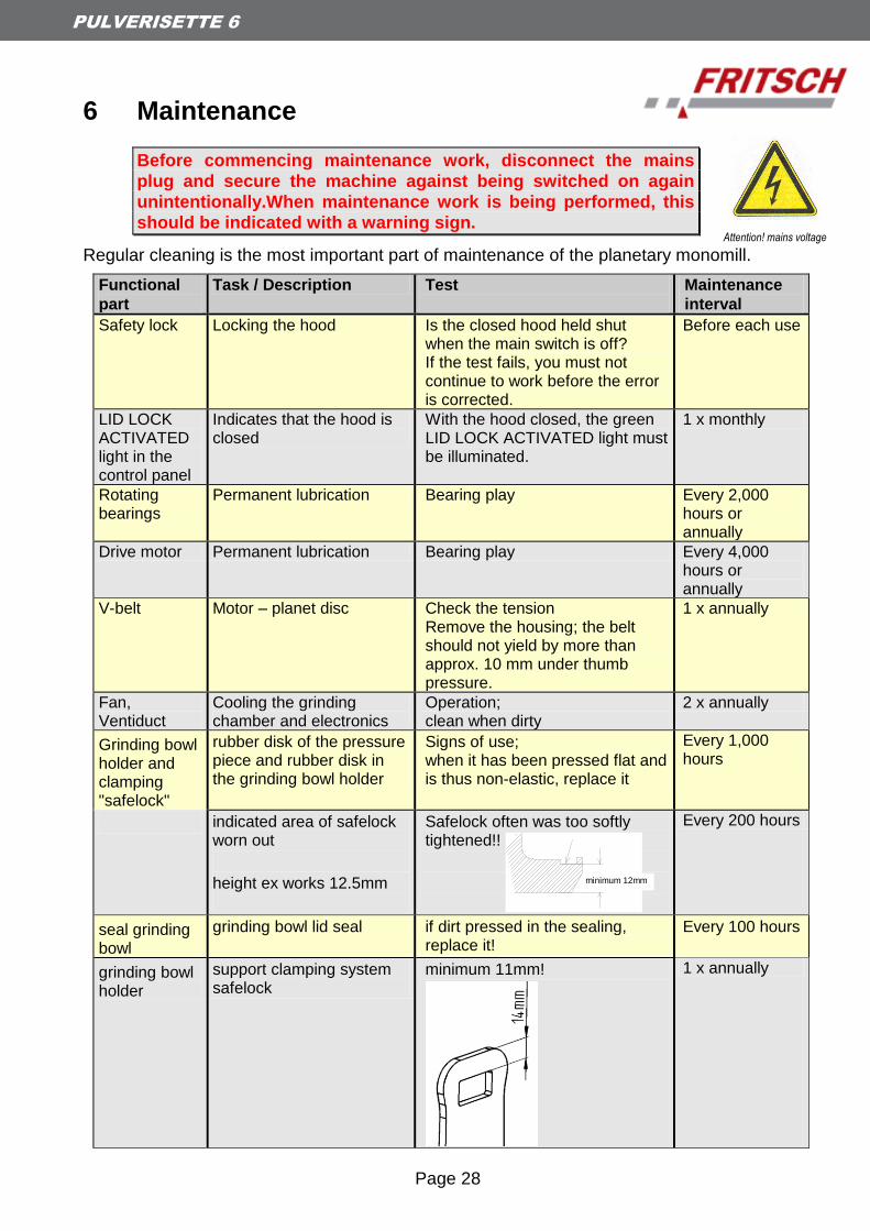
Regular cleaning is the most important part of maintenance of the planetary monomill.
Functional
part
Task / Description Test
Maintenance
interval
Safety lock Locking the hood Is the closed hood held shut when the main switch is off? If the test fails, you must not continue to work before the error is corrected.
Before each use
LID LOCK ACTIVATED light in the control panel
Indicates that the hood is closed
With the hood closed, the green LID LOCK ACTIVATED light must be illuminated.
1 x monthly
Rotating bearings
Permanent lubrication Bearing play Every 2,000 hours or annually
Drive motor Permanent lubrication Bearing play Every 4,000 hours or annually
V-belt Motor – planet disc Check the tension Remove the housing; the belt should not yield by more than approx. 10 mm under thumb pressure.
1 x annually
Fan, Ventiduct
Cooling the grinding chamber and electronics
Operation; clean when dirty
2 x annually
Grinding bowl holder and clamping "safelock"
rubber disk of the pressure piece and rubber disk in the grinding bowl holder
Signs of use; when it has been pressed flat and is thus non-elastic, replace it
Every 1,000 hours
indicated area of safelock worn out
height ex works 12.5mm
Safelock often was too softly tightened!!
Every 200 hours
seal grinding bowl
grinding bowl lid seal if dirt pressed in the sealing, replace it!
Every 100 hours
grinding bowl holder
support clamping system safelock
minimum 11mm!
1 x annually
minimum 12mm
Page 29
PULVERISETTE 6
7 Warranty The warranty card enclosed with the machine upon delivery must be completely filled out and returned to the delivering factory so that the warranty can enter into effect.
Online registration is also possible. More information can be found on your warranty card or on our website http://www.fritsch.de
The company Fritsch GmbH in Idar-Oberstein and your "Technical Application Laboratory" or the corresponding national representatives would be happy to provide you with advice and assistance.
Please include the serial number given on the type plate along with any questions.
Please note that the original Fritsch packaging must be used in the event that the machine is returned. Fritsch GmbH is not responsible for damages resulting from improper packaging (non-Fritsch packaging).
Page 30
PULVERISETTE 6
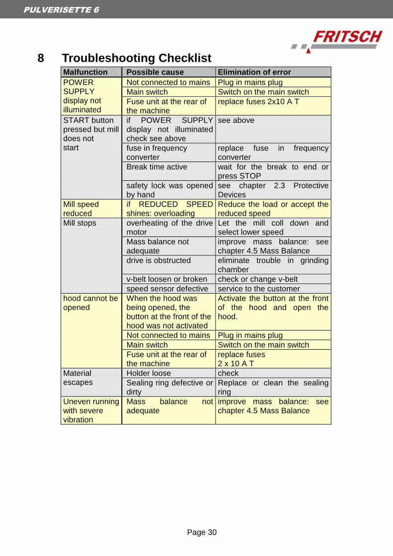
8 Troubleshooting Checklist Malfunction Possible cause Elimination of error
POWER SUPPLY display not illuminated
Not connected to mains Plug in mains plug
Main switch Switch on the main switch
Fuse unit at the rear of the machine 2 x 8 A T
replace fuses 2x10 A T
START button pressed but mill does not start
if POWER SUPPLY display not illuminated check see above
see above
fuse in frequency converter
replace fuse in frequency converter
Break time active wait for the break to end or press STOP
safety lock was opened by hand
see chapter 2.3 Protective Devices
Mill speed reduced
if REDUCED SPEED shines: overloading
Reduce the load or accept the reduced speed
Mill stops overheating of the drive motor
Let the mill coll down and select lower speed
Mass balance not adequate
improve mass balance: see chapter 4.5 Mass Balance
drive is obstructed eliminate trouble in grinding chamber
v-belt loosen or broken check or change v-belt
speed sensor defective service to the customer
hood cannot be opened
When the hood was being opened, the button at the front of the hood was not activated
Activate the button at the front of the hood and open the hood.
Not connected to mains Plug in mains plug
Main switch Switch on the main switch
Fuse unit at the rear of the machine 2 x 8 A T
replace fuses 2 x 10 A T
Material escapes
Holder loose check
Sealing ring defective or dirty
Replace or clean the sealing ring
Uneven running with severe vibration
Mass balance not adequate
improve mass balance: see chapter 4.5 Mass Balance
Page 31
PULVERISETTE 6
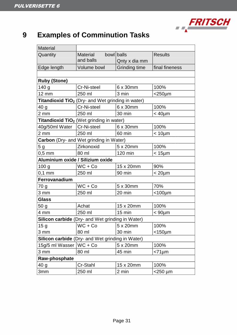
9 Examples of Comminution Tasks
Material
Quantity Material bowl and balls
balls
Qnty x dia mm
Results
Edge length Volume bowl Grinding time final fineness
Ruby (Stone)
140 g Cr-Ni-steel 6 x 30mm 100%
12 mm 250 ml 3 min <250µm
Titandioxid TiO2 (Dry- and Wet grinding in water)
40 g Cr-Ni-steel 6 x 30mm 100%
2 mm 250 ml 30 min < 40µm
Titandioxid TiO2 (Wet grinding in water)
40g/50ml Water Cr-Ni-steel 6 x 30mm 100%
2 mm 250 ml 60 min < 10µm
Carbon (Dry- and Wet grinding in Water)
5 g Zirkonoxid 5 x 20mm 100%
0,5 mm 80 ml 120 min < 15µm
Aluminium oxide / Silizium oxide
100 g WC + Co 15 x 20mm 90%
0,1 mm 250 ml 90 min < 20µm
Ferrovanadium
70 g WC + Co 5 x 30mm 70%
3 mm 250 ml 20 min <100µm
Glass
50 g Achat 15 x 20mm 100%
4 mm 250 ml 15 min < 90µm
Silicon carbide (Dry- and Wet grinding in Water)
15 g WC + Co 5 x 20mm 100%
3 mm 80 ml 30 min <150µm
Silicon carbide (Dry- and Wet grinding in Water)
15g/5 ml Wasser WC + Co 5 x 20mm 100%
3 mm 80 ml 45 min <71µm
Raw-phosphate
40 g Cr-Stahl 15 x 20mm 100%
3mm 250 ml 2 min <250 µm

Page 32
PULVERISETTE 6
Material
Quantity Material bowl and balls
balls
Qnty x dia mm
Results
Edge length Volume bowl Grinding time final fineness
Manganous oxide MnO2 (Wet grinding in Water)
50g/40ml Water WC + Co 15 x 20mm 100%
0,1 mm 250 ml 60 min <20µm
Sewage sludge (dry)
180 g Al2O3 10 x 30mm 100%
8 mm 500 ml 30 min <250µm
Activated charcoal (Wet grinding in Water)
150 ml Cr-Ni-Stahl 15 x 20mm 100%
0,025 mm 250 ml 30 min < 5µm
Gypsum
300 g Cr-Stahl 10 x 30mm 100%
10 mm 500 ml 20 min <200µm
Protein
50 g Sinterkorund 1 6 x 30mm 90%
20 mm 250 ml 90 min < 50µm
Grain (barley)
100 g Sinterkorund 1 3 x 40mm 100%
3 mm 500 ml 20 min < 150µm
Dough
100 g Sinterkorund 1 10 x 30mm 100%
5 mm 500 ml 3 min < 250µm
Sugar (Wet grinding in alcohol)
200 g Achat 10 x 30mm 100%
1 mm 500 ml 45 min < 10µm
Page 33
PULVERISETTE 6
10 Disclaimer Before using this product, these operating instructions are to be carefully read and be understood. Use of the product requires expertise and it is to be carried out only by commercial users. The product may be used exclusively for the applications outlined in these instructions and within the scope of the regulations set out in these operating instructions, and it shall subject to regular maintenance. In the event of infringements of these instructions and/or improper use or maintenance, the customer assumes full liability for the functionality of the product and for such damage or injury as may occur as a result of breaching these obligations.
The content of these operating instructions is subject as a whole to copyright protection. This operating manual and its content may not, in any form, in whole or in part, be reproduced, further distributed or saved without the prior written consent of Fritsch GmbH
These operating instructions have been compiled to the best of our knowledge and belief and checked for relevance at the time of printing. FRITSCH GMBH does not accept any warranty or guarantee for the accuracy or completeness of the content in these operating instructions, including, but not limited to, the tacit warranties of merchantability and suitability for a particular purpose, unless applicable laws or adjudications prescribe a liability.
FRITSCH GMBH expressly reserves the right to amend and/or to update these operating instructions without prior notice. The same applies to changes and improvements to the products described in these operating instructions. The onus for obtaining information about the current status of these operating instructions lies with the individual user. In this regard, please contact the FRITSCH GMBH distributor in your area or apply directly to Fritsch GmbH, Industriestrasse 8 D-55473 Idar-Oberstein, Germany.
Not all parts illustrated must be built into the product. A right to delivery of these parts does not exist. If interested in them, please contact the FRITSCH GMBH distributor in your locality or Fritsch GmbH, Industriestrasse 8, D-55743 Idar-Oberstein directly.
FRITSCH GMBH endeavours, with the greatest of care, to continually improve the quality, reliability and safety of their products and to conform with the state of the art. The products supplied, as well as these operating instructions, correspond with, at the time of transfer from the influence area of FRITSCH GMBH, the respective state of the art.
Customers agree and acknowledge that, through usage of the product, defects, faults or errors cannot be ruled out entirely. To avoid the risks thereof, of damage to persons or property being incurred, or of any other direct or indirect damages, customers must provide for adequate and comprehensive safety measures whilst working with the product.
Page 34
PULVERISETTE 6
Fritsch GmbH expressly disclaims every explicit or implied, contractual or arising from improper handling or a fixed contractual, statutorial or other liability, warranty or other obligation in respect of compensation obligations. Under no circumstances shall Fritsch GmbH accept liability, resp., are you entitled to compensation, for any special, direct, indirect, incidental, or consequential damages, including but not limited to lost profits, lost savings, lost revenues or economic losses of any kind, or for compensation obligations towards third parties for downtime, goodwill, damage to or replacement of equipment and property, for the costs or restoration of materials or goods in connection with the product or the utilisation of our products, for other damage or personal injury (including death) or the like. In so far as the law or adjudications require a mandatory liability, the above disclaimer is to be considered as limited. A liability for negligence is excluded in every case.
No explicit, implied or other rights of usage are granted for patents, trademarks or other intellectual property rights. Likewise, we assume no responsibility for patent infringements or violations of the rights of third parties arising from the use of this product.
Both adherence with these operating instructions and the conditions and methods of installation, operation, usage and maintenance of the product cannot be monitored by Fritsch GmbH. Improper execution of the installation can lead to property damage and, as a result, also place people at risk. Accordingly, we accept no responsibility or liability for losses, damages or expenses resulting from, or in any way connected with, defective installation and improper operation, as well as from incorrect utilisation and maintenance.

Page 35