operating manual - nova-sail.com operating manual.pdf · next sail begins to ensure the value...
TRANSCRIPT

Operating Manual

NS360 Operating Manual2
Introduction. . . . . . . . . . . . . . . . . . . . . . . . . . . . . . . . . . . . . . . . . . . . . . . . . . . . 3
Installation . . . . . . . . . . . . . . . . . . . . . . . . . . . . . . . . . . . . . . . . . . . . . . . . . . . . 4Controls and display description . . . . . . . . . . . . . . . . . . . . . . . . . . . . . . . . . . 5
• Modes and sub-modes................................................................. 5
Operations. . . . . . . . . . . . . . . . . . . . . . . . . . . . . . . . . . . . . . . . . . . . . . . . . . . . . 6• Switching power on and off .......................................................... 6• Switching backlight on and off...................................................... 7• Switching modes and sub-modes ................................................ 7• Speed mode ................................................................................. 8• To reset the maximum speed ....................................................... 8• To reset the trip distance .............................................................. 9• Magnetic heading compass mode................................................ 9• VMG mode ................................................................................. 10• To set and adjust the wind direction ........................................... 10• Wind shift indicator mode ........................................................... 11• Memorization of the tack lines.................................................... 11• TIMER mode .............................................................................. 13• Start line distance ...................................................................... 14• Waypoint mode ......................................................................... 15
Advanced Operations . . . . . . . . . . . . . . . . . . . . . . . . . . . . . . . . . . . . . . . . . . 17• SET mode .................................................................................. 17• Compass offset (angle of magnetic variation/declination).......... 19• Boat offset ................................................................................. 20• Exit timer mode ......................................................................... 21• Exit mode of the start line........................................................... 22• Enable or disable the GPS functions.......................................... 22• Enable or disable the race functions ......................................... 23• Reset to factory compass calibration values .............................. 23
User calibration of the magnetic compass . . . . . . . . . . . . . . . . . . . . . . . . . 24
Limited Warranty . . . . . . . . . . . . . . . . . . . . . . . . . . . . . . . . . . . . . . . . . . . . . . 30Disclaimer . . . . . . . . . . . . . . . . . . . . . . . . . . . . . . . . . . . . . . . . . . . . . . . . . . . . 31
Contents

Introduction
For the first time, with the NS360, you can find a speedo and a magnetic compass in one product, along with the all-essential race functions : wind shift indicator, VMG, direction, speed and distance to the waypoints, start line distance and race timer.
Compact (125 mm x 80 mm x 26 mm) and intuitive, the NS360 is lighter (240 grams) than any existing system, wired or wireless. It is also waterproof and robust, being made of bombproof polycarbonate and anodized aluminium. Powered with only one standard AA battery, the NS360 gives sailors accurate and vital information for over 30 hours. It can be installed in minutes and there is no need to drill a hole in the hull or use a wired connection.
We hope you enjoy sailing with the NS360, and encourage you to read this manual thoroughly, to learn about the many features of your exciting new Novasail product.
NS360 Operating Manual 3

NS360 Operating Manual4
The mounting location should be as far as possible from any magnetic objects to avoid any interference with the compass sensor.The NS360 should be mounted as close as possible to the vertical and horizontal planes.
Note : Wherever you mount the NS360, it shouldn’t be flush to any thick surface such as the hull, so that the sensitivity of the embedded GPS receiver is not affected.
Installation

S
Controls and display description
Modes and sub-modes
Speed : SP• SPI : Instant speed• SPA : Average speed• SPM : Maximum speed• TRP : Total distance
Magnetic Heading : MH• MHH : High sensitivity• MHM : Medium sensitivity• MHL : Low sensitivity
Velocity Made Good : VMGWind Shift Indicator : WINTIMER : TIMStart Line Distance : SLDWaypoints : WP
• WP1 to WP9 : Waypoint 1 to 9
Battery Backlight
DataModeTo switch the sub-modesSelect the tack linesAdjust the timer valueSelect the start line points
econdarydisplay
Primary display
Switch modes
Start/stop the NS360Start/stop the backlightMemorize wind directionMemorize the tack linesStart/stop the timerMemorize start line pointsMemorize waypoints
NS360 Operating Manual 5

Operations
Switching power on and off
• Make sure the battery is installed with the correct polarity and has enough remaining power (positive pole inserted first)
• Press to start the device. A beep will be emitted• Press and hold for more than 4 seconds until the screen displays OFF
and the sequence “3”, “2”, “1” is finished. A beep will be emitted when the device turns off
The device will turn off automatically when it remains in the horizontal position for more than 3 minutes. A beep will be emitted 3 seconds before it turns off.
Note : If the device does not turn on, you need to check if the battery is fully charged, that the battery compartment is dry, and the polarity is correct.
Note : Until enough satellites are locked, the NS360 is not ready to use. For the sub-modes SPI, SPA and TRP and the modes VMG, SLD and WP, the screen displays : ”---”. For the SPM sub-mode, the maximum value is displayed but blinking until readyness.
Note : Alkaline batteries should be used in order to result in a maximum lifespan of 30 hours. When using a disposable battery, it is also recommended to remove it if the device is not used for a prolonged period of time (in order to avoid a possible leakage inside the battery compartment).If using rechargeable batteries, low self discharge rate battery types are preferred, because normal rechargeable batteries lose their stored energy more quickly. Recommended batteries are SANYO ENELOOP, GP RECYKO+ or UNIROSS HYBRIO. This kind of rechargeable battery will last for approximately 20 hours.
NS360 Operating Manual6

Operations
Switching backlight on and off
• Press and hold for more than 1 second until the icon is displayed on the screen. If the OFF sequence starts, simply release the button before the sequence “3”, “2”, “1” is finished.
• To turn off the backlight, press and hold for more than 1 second until the icon disappears from the screen.
Note : When you press and hold the select button to switch on/off the backlight, you will not make any selection and therefore will not change any parameter.
Switching modes and sub-modes
• To have two different separate readings, first choose the mode and sub-mode required on the primary display by pushing and then the arrows
for the sub-mode selection. Then, display the selected sub-mode on the secondary display using the button.
• You are free to choose another mode/sub-mode on the primary display.
Note : Any sub-mode selection on the primary display will affect automatically the secondary display when both displays are in the same mode.
NS360 Operating Manual 7

Operations
SPeed mode
This mode provides the speed over ground of the boat as measured by the GPS receiver. Several speeds are available through the sub-modes : Instant, Average and Maximum as well as the trip distance.
• Use the arrows to scroll the sub-modes.
SPeed sub-modes
• SPI : SPeed InstantThe Instant speed of the boat is displayed in knots (kts) with an accuracy of 0.1 knot. The minimum speed is 1 knot, and the maximum speed is 99.9 knots.
• SPA : SPeed AverageThis sub-mode provides the average speed of the boat during the past 3 seconds. This is particularly useful when sailing with big waves upwind or downwind with lots of speed changes.
• SPM : SPeed MaximumThe Maximum speed that the boat has reached since the last reset.
Note : For that sub-mode, don’t forget to reset the maximum speed before your next sail begins to ensure the value displayed refers to the new trip.
To reset the maximum speed :• Display SPM sub-mode in the lower screen using the arrows • Press
• TRP : TRiP distanceThe TRP mode displays the total distance made by the vessel since the last reset.
NS360 Operating Manual8

Operations
Note : For that sub-mode, don’t forget to reset the trip before your next sail begins to ensure the value displayed refers to the new trip.
To reset the trip distance :• Display TRP sub-mode in the lower screen using the arrows • Press
Magnetic Heading compass mode
To win races you need to react to even small wind shifts. The NS360 digital compass delivers precise and reliable heading information to help you to tack and jibe at the most suitable times.
The sensitivity of the compass can easily be adjusted to High, Medium or Low by scrolling through the sub-modes.
• Use the arrows to scroll the sub-modes.
Sub-modes of the Magnetic Heading compass :
• MHH : Magnetic Heading High sensitivityWhen sailing with light winds and flat seas, High sensitivity allows you to appreciate very small wind variation.
• MHM : Magnetic Heading Medium sensitivityMedium sensitivity is more suitable for race boats under medium wind and sea conditions. Dinghy racers will appreciate this mode.
• MHL : Magnetic Heading Low sensitivityUnder Low sensitivity more subtile variations due to big waves and sudden gusts are filtered.
NS360 Operating Manual 9
Operations
Note : The magnetic variation of the area of use can be compensated by adjusting the compass offset. Please refer to the Advanced Operations “Compass offset”, page 19 for more details on the compass offset adjustement.
VMG mode
This mode provides the projected speed of the boat on the wind direction. The higher the value, the faster the vessel is going upwind or downwind. First, the wind direction must be set to display a VMG value on the data line. If no wind direction is set, the screen displays “---”. The VMG is displayed in knots (kts).
To set and adjust the wind direction in VMG mode• Press to capture the wind direction as the current heading value.• Adjust the wind direction value with the arrows
Note : Each time you press , the Magnetic Compass Heading is used as the wind direction.
Note : The wind direction may also be calculated from the the starboard and port tack lines if you have already set the values in the WIN mode. (See WIN mode, page 11)
Note : When you memorize a wind direction in VMG mode, the tack lines in WIN mode are updated, assuming that the boat makes the same upwind angle on startboard and port.
NS360 Operating Manual10

Operations
WINd shift indicator mode
Used in Wind Shift Indicator (WIN) mode, the NS360 displays numerical values of the wind shifts allowing an immediate and effortless interpretation. To use this mode, you need to memorize the tack lines on startboard and port.
Memorization of the tack lines :• Sail upwind to your optimal VMG• “D 1” is displayed on the data line of the lower screen• Press to use the current magnetic compass heading as the one of the
tack line directions.• The wind shift value is immediately displayed• Press the arrows to display “D 2” on the data line of the lower
screen• Sail upwind to your optimal VMG on the other tack line• Press to use the current magnetic compass heading as the other tack
line direction
VMG
Vwasted
Vactual
Wind Direction
VMG DIAGRAM
NS360 Operating Manual 11

Operations
Note : The sequence of memorization of the tack lines on starboard and port is not defined. You can do starboard then port or vice versa.
The WIN mode displays an angle in degrees which corresponds to the difference between the tack line direction and the current magnetic compass heading of the boat. It displays ’H’ (for Heading) in front of the value if the wind is heading, and ’L’ (for Lift) in front of the value if the wind is lifting. When sailing upwind, you need to sail inside the lifts ’L”.When sailing downwind, the WIN mode will display ’d’ (for downwind) in front of the value of the deviation from the wind direction.
Note : The first tack line memorized is by default considered to be the starboard line. However, if this was the port tack line, the product will understand it automatically.
LIFT
Wind direction
Starboard tack line Port tack line
HEADER
fig.1 WIN mode diagram when sailing on starboard
NS360 Operating Manual12

Operations
TIMER mode
This mode offers a countdown timer which can be set from 1 to 9 minutes. When counting down, a short beep sounds :
• each minute until the last minute• each ten seconds until 10 seconds • each second until the start time
At the start time :• a long beep sounds• the timer starts counting the race duration in minutes and hours
Adjust, start and stop the TIMER :• Adjust the timer value with the arrows .• Press to start and stop the TIMER.
Resynchronize the TIMER to the nearest minute :When the TIMER is running, at any time, you can resynchronize to the upper or lower minute
• Press the arrow to resynchronize the value to the upper minute.• Press the arrow to resynchronize the value to the lower minute.
Note : The timer continues to count down until you press to stop it, even during resynchronization. When stopped, the display blinks and the timer remains frozen.
Note : After the start, the timer will switch automatically to the mode defined in the SET mode. Please refer to the Advanced Operations “Exit Timer mode”, page 21 for more details. (The default value of the Exit Timer mode parameter is “SP” mode).
NS360 Operating Manual 13

Operations
Start Line Distance
Knowing the exact distance in meters to the start line gives a huge advantage in helping you start ahead of the fleet and even win the race. The NS360 start line distance function is the most advanced on the market as it combines a 1 meter accuracy and a dynamic boat offset compensation calculated with the real boat magnetic heading to the start line.The accuracy of the distance is 1 meter but it’s safer to take a bigger margin. The maximum distance is 999 meters.
The start line consists of 2 points “P 1” and “P 2” that have to be aligned with the start line :
• P1 : Commitee boat• P2 : Pin
Memorize the start line points ’P 1’ and ’P 2’• ’P 1’ is displayed on the data line of the lower screen.
NS360 Operating Manual14

Operations
• Press when you reach the committee boat reference point.• ’P 2’ is now displayed on the data line of the lower screen.• Press when you reach the pin reference point.• The distance is meter is now displayed on the data line.
Note : If the start line is modified by the committee, you may be required to re-enter one or both reference points. It can be done by pressing the arrows
to select the desired reference point and to memorize it by pressing
Note : The distance from the front of the boat to the NS360 is called the Boat OFfset (BOF). Please refer to Advanced Operations “Boat offset”, page 20 for more details on the boat offset adjustment.
Note : After the start, the Start Line Distance (SLD) will switch automatically to the mode defined in the SET mode. Please refer to the Advanced Operations “Exit Start Line mode”, page 22 for more details. (The default value of the Exit Start Line mode parameter is “MH” mode).
WayPoint mode
Boats doing Island races are usually turning the same marks but in different orders. The waypoint mode has been made for those who are sailing island races and require information such as the direction, the speed and the distance to reach the selected pre-defined waypoint. Up to 9 waypoints can be memorized : WP1, WP2…to WP9. Each time a waypoint is selected, the direction, speed and distance to reach it are displayed sequentially every 4 seconds.
To use a waypoint• By default, WP1 is displayed on the mode line.• Press the arrows to select the required waypoint, from WP1 to
WP9.
NS360 Operating Manual 15

Operations
• The direction, speed and distance are displayed sequentially every 4 seconds.
To Memorize a waypoint• Press the arrows to select the waypoint (from WP1 to WP9) that
you want to overwrite.• Press to memorize the current boat position into the selected waypoint.• The direction, speed and distance to reach it are displayed sequentially
every 4 seconds.
The waypoint speed displayed in knots is calculated using the waypoint position, the boat position, the boat speed and the heading.The sign ’+’ means that you are approaching the waypoint and ’-’ that you are going in the opposite direction.
WP speed
Speed
NS360
Waypoint position memorized
WayPoint Speed DIAGRAM
NS360 Operating Manual16

Advanced Operations
SET mode
The SET mode allows the adjustment of your NS360 parameters sequentially as follows :
• Compass offset• Boat offset• Exit mode of the Timer• Exit mode of the Start Line• GPS module activation : on/off• Race functions activation : on/off• Reset the product to the factory default values• Compass calibration
Note : GPS and Race functions can be turned off if your sailing class does not allow them. OFF is displayed when you select any mode using the GPS and/or Race functions.
To enter the SET mode :• Press and the upper screen simultaneously. “SET” is displayed on
the data line of the upper screen. • Each parameter is displayed on the mode line of the lower screen.• You can select the required value for each parameter using the arrows
.• Press to memorize the parameter value and switch to the next
parameter.• You exit the SET mode automatically after the last parameter is memorized.
Note : Each parameter is memorized when is pressed and before the next parameter is displayed, except for reset and calibration.
NS360 Operating Manual 17

Advanced Operations
The NS360 will automatically exit the SET mode upon completion of all parameters.
Note : You can also exit the SET mode anytime by switching off and on the product.
Name Display Description
Compass OFfset COFThis allows to compensate the magnetic deviation. The default value is 0
Boat OFfset BOFThis is the length between the front of the boat and the NS360- default value 0, can be adjusted in 0.1 meter increments.
Exit TImer mode ETI- default alternate mode is the Speed mode- All other modes can be selected
Exit Start Line mode
ESL- default alternate mode is the Magnetic Heading mode- All other modes can be selected
GPS activation GPS- ON- OFF (if your sailing class does not allow it during races)
RACe functions activation
RAC- ON- OFF (if your sailing class does not allow it during races)
RESet to factory default values
RES - ON to retrieve factory values- OFF by default
Compass CaLibration CAL
- ON to start- OFF by default
NS360 Operating Manual18

Advanced Operations
Compass offset (angle of magnetic variation/declination)
Because the angle of variation varies with respect to the geographic position, the NS360 must be adjusted according to the specific location to achieve the maximum accuracy and synchronization between the GPS unit and the magnetic compass. The angle of variation is the actual angle observed between the true North geographic position and the actual North magnetic position.
To compensate for the magnetic variation, you need to adjust the parameter COF (Compass Offset) as follows :
• Switch off your NS360.• Press and the upper screen simultaneously. ’SET’ is displayed on
the upper line of the display.• COF (Compass Offset) is displayed on the mode line of the lower screen• Use the arrows to enter the required variation corrective value The
first digit will display ’W’ or ’E’ for a west or a east variation, and the remaining 2 digits are the actual angle, adjustable from 0 to 45 degrees.
• Press to store the value, BOF (Boat Offset) is now displayed.• Go through all the parameters to exit the SET mode or press and hold for
more than 4 seconds until the device turns off.
NS360 Operating Manual 19

Advanced Operations
There are a number of resources available on the web that compute angles of variation for any location in the world. A “world Magnetic Model Calculator” is available from both the National Geophysical Data Center and the British Geological Survey :
• http://www.ngdc.noaa.gov/seg/geomag/jsp/struts/calcDeclination• http://www.geomag.bgs.ac.uk/gifs/wmm_calc.html
Here’s some examples of magnetic variation for different geographic locations : • Hong Kong : 2 degrees west• Melbourne : 11 degrees east• Marseille : 0 degree• San Francisco : 14 degrees east
Boat offset
The boat offset corresponds to the distance from the front of the boat to the NS360. The remaining distance to the start line is calculated taking the boat offset and the current magnetic heading into account. The default value is 0, the maximum value is 99.9 meters and the increment is 0.1 meter.
Example : The real distance between the front of the boat to the NS360 is 3.2 meters. You need to enter a boat offset equal to 3.2 meters. Then, considering that the NS360 is 10 meters from the line. When you face the start line, the displayed remaining distance is equal to the 10-3.2 meters, 6 meters. However, using the magnetic heading of the boat, if you sail parallel to the line, then the display value is equal to the real distance between the line and the NS360, 10 meters.
• Switch off your NS360.• Press and the upper screen simultaneously. ’SET’ is displayed on
the data line of the upper screen .• Press until BOF (Boat Offset) is displayed on the mode line of the lower
screen.
NS360 Operating Manual20

Advanced Operations
• Use the arrows to enter the length between the front of the boat to your NS360.
• Press to store the value, ETI (Exit mode of the Timer) is now displayed.• Go through all the parameters to exit the SET mode or press and hold for
more than 4 seconds until the device turns off.
Exit Timer mode : ETI
After the start, the Timer mode is not needed anymore, for this reason the NS360 will switch automatically to the desired exit mode by simply setting the parameter ETI (Exit Timer mode) as follows :
• Switch off your NS360.• Press and the upper screen simultaneously. ’SET’ is displayed on
the data line of the upper screen.• Press until ETI (Exit Timer mode) is displayed on the data line of the
lower screen.• Use the arrows to select the desired exit mode for your NS360.• Press to store the value, ESL is now displayed.• Go through all the parameters to exit the SET mode or press and hold for
more than 4 seconds until the device turns off.
Note : Only a mode (SP, MH, VMG, WIN, TIM, SLD, WP) and not a sub-mode (SPI, SPA, SPM, TRP, MHL, MHM, MHH, WP1, ...etc) can be memorized in the ETI parameter. However, the timer will switch automatically to the memorized mode and the sub-mode that you are currently using.
Note : The mode by default is SP (Speed mode).
NS360 Operating Manual 21

Advanced Operations
Exit mode of the Start Line : ESL
After the start, the Start Line Distance (SLD) mode is not needed anymore, for this reason the NS360 will switch automatically to the desired exit mode by simply setting the parameter ESL (Exit mode of the Start Line) as follows :
• Switch off your NS360.• Press and the upper screen simultaneously. ’SET’ is displayed
on the data line of the upper screen.• Press until ESL (Exit mode of the Start Line) is displayed on the data line
of the lower screen.• Use the arrows to select the desired exit mode for your NS360.• Press to store the value, GPS (GPS function parameter) is now
displayed.• Go through all the parameters to exit the SET mode or press and hold for
more than 4 seconds until the device turns off.
Note : The ESL parameter can only be a mode (SP, MH, VMG, WIN, TIM, SLD, WP) and not a sub-mode (SPI, SPA, APM, TRP, MHL, MHM, MHH, WP1, ...etc). However, the SLD will switch automatically to the memorized mode and the sub-mode that you are currently using.
Note : The mode by default is MH (Magnetic Heading mode).
Enable or disable the GPS functions : GPS
If your boat class does not allow electronic navigation aids and/or a speedometer, you are required to switch off all the functions issued with the embedded GPS module. When the GPS feature is turned off, the battery life is increased to approximately 150 hours. To check more details about the functions affected when switching off the GPS module, please refer to the table 1 : GPS and Race functions activation.
NS360 Operating Manual22

Advanced Operations
Enable or disable the RACe functions : RAC
If your boat class does not allow on board electronic navigation aids, you may be required to switch off the race functions. For more details about the modes affected when switching off the race functions, please refer to the table 1 : GPS and Race functions activation.
Note : During normal usage, if you select a mode which has been disabled by setting off the GPS and/or the race functions, then ’OFF’ will be displayed on the screen.
RESet to factory compass calibration values : RES
When set to ON and when the select key is pushed, the default factory calibration values of the compass are restored and the NS360 is powered off automatically.
Table 1: GPS and Race functions activation
GPS Off RAC OffSpeed : SP(SPI/ SPA/ SPM/ TRP)
Off On
Magnetic Heading : MH(MHH/ MHM/ MHL)
On On
Velocity Made Good : VMG Off Off
Wind Shift Indicator : WIN On Off
Timer : TIM On On
Start Line Distance : SLD Off Off
Waypoint : WP(WP1/ WPx/ .../WP9)
Off Off
NS360 Operating Manual 23
Calibration
User CALibration of the magnetic compass : CAL
When set to ON and when the select key is pushed, the NS360 enters a set of sub-menus to allow a user calibration of the magnetic compass. There are 10 sub-menus for which the user has to follow the sequence described below.To allow the maximum accuracy of the calibration procedure, it is recommended to perform this outdoors to avoid any magnetic disturbing fields. A wooden surface is highly recommended (eg a table) and it is necessary to ensure that there are no ferrous materials nearby (wrist watches should be removed).
To start with draw 2 perpendicular lines (X and Y axis) on a perfectly horizontal plan. On the lower screen of the display, the calibration sub-menu number is displayed. There are 10 steps to follow in order to complete the calibration of your NS360. Upon completion of the sequence, the NS360 will memorize the new values and shut down automatically. If the NS360 is shut down during the calibration, nothing will be memorized.
Note : Whenever necessary, the factory calibration values can be restored at any time by setting the RES menu to ON in the SET mode.
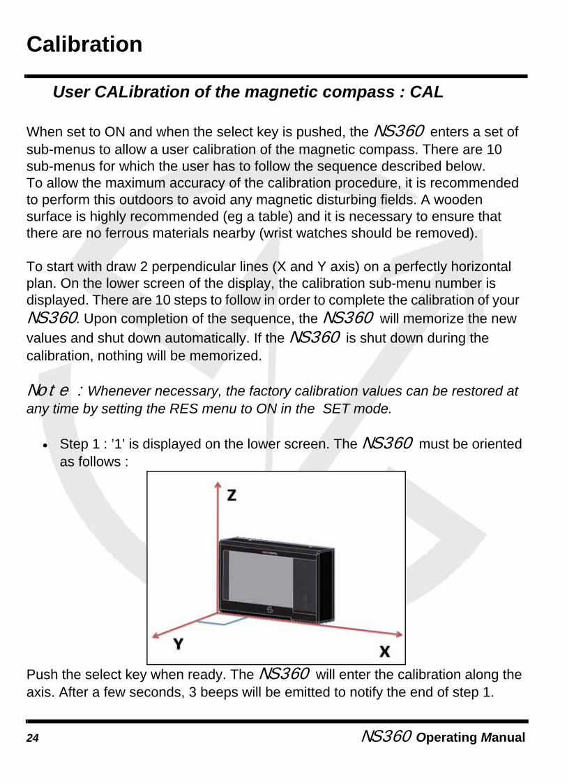
• Step 1 : ’1’ is displayed on the lower screen. The NS360 must be oriented as follows :
Push the select key when ready. The NS360 will enter the calibration along the axis. After a few seconds, 3 beeps will be emitted to notify the end of step 1.
NS360 Operating Manual24

Calibration
• Step 2 : ’2’ is now displayed on the lower screen. The NS360 must be oriented as follows :
Push the select key when ready. The NS360 will enter the calibration along the axis. After a few seconds, 3 beeps will be emitted to notify the end of step 2.
• Step 3 : ’3’ is now displayed on the lower screen. The NS360 must be oriented as follows :
Push the select key when ready. The NS360 will enter the calibration along the axis. After a few seconds, 3 beeps will be emitted to notify the end of step 3.
NS360 Operating Manual 25
Calibration
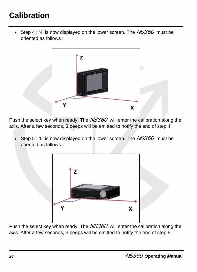
• Step 4 : ’4’ is now displayed on the lower screen. The NS360 must be oriented as follows :
Push the select key when ready. The NS360 will enter the calibration along the axis. After a few seconds, 3 beeps will be emitted to notify the end of step 4.
• Step 5 : ’5’ is now displayed on the lower screen. The NS360 must be oriented as follows :
Push the select key when ready. The NS360 will enter the calibration along the axis. After a few seconds, 3 beeps will be emitted to notify the end of step 5.
NS360 Operating Manual26

Calibration
• Step 6 : ’6’ is now displayed on the lower screen. The NS360 must be oriented as follows :
Push the select key when ready. The NS360 will enter the calibration along the axis. After a few seconds, 3 beeps will be emitted to notify the end of step 6.
• Step 7 : ’7’ is now displayed on the lower screen. The NS360 must be oriented as follows :
Push the select key when ready. The NS360 will enter the calibration along the axis. After a few seconds, 3 beeps will be emitted to notify the end of step 7.
NS360 Operating Manual 27

Calibration
• Step 8 : ’8’ is now displayed on the lower screen. The NS360 must be oriented as follows :
Push the select key when ready. The NS360 will enter the calibration along the axis. After a few seconds, 3 beeps will be emitted to notify the end of step 8.
• Step 9 : ’9’ is now displayed on the lower screen. The NS360 must be oriented as follows :
Push the select key when ready. The NS360 will enter the calibration along the axis. After a few seconds, 3 beeps will be emitted to notify the end of step 9.
NS360 Operating Manual28

Calibration
• Step 10 : ’10’ is displayed on the lower screen. The NS360 must be oriented as follows :
Push the select key when ready. The NS360 will enter the calibration along the axis. After a few seconds, 3 beeps will be emitted to notify the end of step 10.
The NS360 will store the new values and switch off automatically.
NS360 Operating Manual 29

NS360 Operating Manual30
This product meets or exceeds all of Novasail’s rigorous quality controls and inspection standards. Complete services will be provided in accordance with the statement of warranty set forth below if any manufacturing defect or natural failure occurs within the warranty period.
Warranty Terms and Conditions
• If any defect arises under normal conditions of use within the warranty period, our customer service center or specified partner will provide the required repair services at no charge, or legally applicable services according to the appropriate consumer protection laws and regulations of the country in which the product was purchased by the warranty holder.
• The product has to be registered using the online service available on the Novasail web site: www.nova-sail.com
• Please submit the proof of purchase (Invoice) when requesting service.• The actual cost of repair may be charged to the customer or the
performance of warranty service may be rendered impossible, even within the warranty period, under the following circumstances:
• Product failure caused by accident or carelessness• Disassembly or modification for purposes other than it was
originally intended for• Failure caused by a fire, earthquake or flood• Damage/failure caused by an impact• Failure caused by inappropriate services performed by anyone
other than Novasail’s customer service center or one of Novasail’s service specified partners
• For assitance in obtaining service, please contact Novasail service center:
E-mail: [email protected]
Limited warranty

DISCLAIMER
NS360 Operating Manual 31
Information in this document is provided solely in connection with NOVASAIL LTD products. NOVASAIL LTD reserves the right to make changes, corrections, modifications or improvements to this document and the products described herein at any time, without notice.
All NOVASAIL LTD products are sold pursuant to NOVASAIL LTD’s terms and conditions of sale.
Purchasers are solely responsible for the choice, selection and use of the NOVASAIL LTD products described herein, and NOVASAIL LTD assumes no liability whatsoever relating to the choice, selection or use of the NOVASAIL LTD products described herein.
UNLESS OTHERWISE SET FORTH IN NOVASAIL LTD’S TERMS AND CONDITIONS OF SALE, NOVASAIL LTD DISCLAIMS ANY EXPRESS OR IMPLIED WARRANTY WITH RESPECT TO THE USE AND/OR SALE OF NOVASAIL LTD PRODUCTS, INCLUDING WITHOUT LIMITATION IMPLIED WARRANTIES OF MERCHANTABILITY OR FITNESS FOR A PARTICULAR PURPOSE (AND THEIR EQUIVALENTS UNDER THE LAWS OF ANY JURISDICTION).UNLESS EXPRESSLY APPROVED IN WRITING BY AN AUTHORIZED NOVASAIL LTD REPRESENTATIVE, NOVASAIL LTD PRODUCTS ARE NOT RECOMMENDED, AUTHORIZED OR WARRANTED FOR USE IN MILITARY, AIR CRAFT, SPACE, LIFE SAVING, OR LIFE SUSTAINING APPLICATIONS, NOR IN PRODUCTS OR SYSTEMS WHERE FAILURE OR MALFUNCTION MAY RESULT IN PERSONAL INJURY, DEATH, OR SEVERE PROPERTY OR ENVIRONMENTAL DAMAGE.
Resale of NOVASAIL LTD products with provisions different from the statements and/or technical features set forth in this document shall immediately void any warranty granted by NOVASAIL LTD for the NOVASAIL LTD product or service described herein and shall not create or extend in any manner whatsoever, any liability of NOVASAIL LTD.

© 2008 NOVASAIL - All rights reservedwww.nova-sail.com