operating manual for stream selector
TRANSCRIPT
OPERATING MANUAL
FOR
STREAM SELECTOR
Manufactured By:
SAMYAK INSTRUMENTATION PVT. LTD. F-4 Memnagar complex, Opp. Petrol Pump Memnagar, Ahmedabad, India-380 052
Phone: +91-79-2749 5500/5600 FAX: +91-79-27417997
URL: http//www.samyak.com Email [email protected]

STREAM SELECTOR SAMYAK
OPERATING MANUAL VER 3.11 Page 2 of 24
INDEX
CHAPTER 1 .................................................................................................................................. 3
1.1 INTRODUCTION ................................................................................................................... 3
CHAPTER 2 .................................................................................................................................. 4
2.1 SYSTEM DESCRIPTION ...................................................................................................... 4
2.2 HARDWARE DESCRIPTION .............................................................................................. 5
2.3 INSTALLATION GUIDE ....................................................................................................... 7
CHAPTER 3 OPERATING DETAILS ....................................................................................... 8
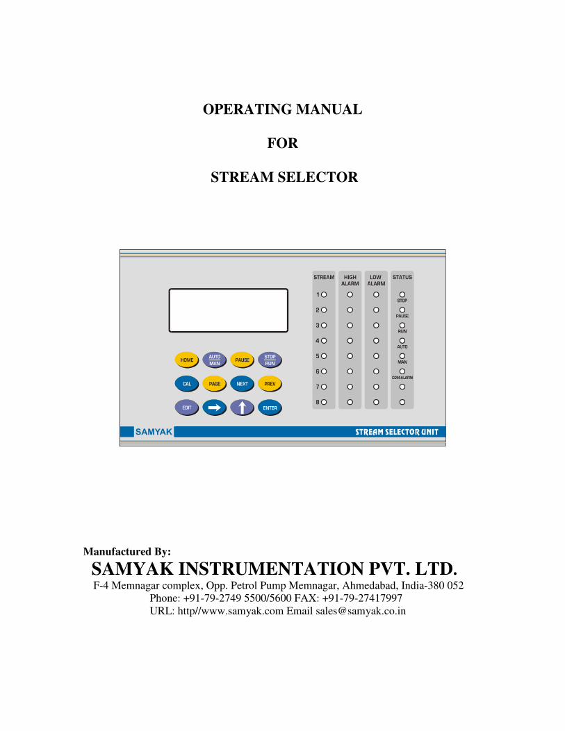
3.1 DISPLAY & KEYBOARD ............................................................................................................ 8
3.2 EDIT MODE ............................................................................................................................... 9
CALIBRATION MODE ............................................................................................................. 11
3.3 HOW TO ENTER/MODIFY PARAMETER VALUE ................................................................... 14
1 RUN MODE ............................................................................................................................. 14
2 STOP MODE ........................................................................................................................... 14
3.4 RUN MODE .......................................................................................................................... 15
3.4.1 MANUAL MODE ............................................................................................................. 15
3.4.2 AUTO MODE .................................................................................................................... 16
IN PULSE MODE ........................................................................................................................ 16
IN TIME MODE .......................................................................................................................... 16
3.5 CALIBRATION MODE ....................................................................................................... 17
3.5.1 INPUT CALIBRATION .................................................................................................... 19
3.5.2 OUTPUT CALIBRATION: ............................................................................................... 19
3.12 FLOW CHECK LOGIC:.................................................................................................... 22
CHAPTER 4 ................................................................................................................................ 23
4.2 TERMINAL DETAILS ............................................................................................................... 24

STREAM SELECTOR SAMYAK
OPERATING MANUAL VER 3.11 Page 3 of 24
CHAPTER 1
1.1 INTRODUCTION
This STREAM SELECTOR UNIT is upgraded version of Samyak make stream selector.
The unit has 20 characters x 4 lines LCD. This makes it more users’ friendly. It is based
on a popular 8-bit Microcontroller. The system is designed to control stream selection of
up to eight-stream system using its Relay outputs and sync Input or Timer. It also
generates Sample and Hold analog outputs for each channel.
1.2 SPECIFICATIONS:
1. No. of Streams Up to 8
2. Mains supply
110-230V AC +/- 10%
Single phase, 50 Hz Nominal
3. Key board 12 keys keypad
4. Display
20 * 4 LCD display
32 Discrete LEDs for Relay/process status Indication
5. Relays
For stream selection
8 Powered relay contacts
8Potential free contacts
For high Alarm &
Low Alarm
8 Powered contact
8Potential free contacts
For common alarm
1 Powered relay contacts
1Potential free contacts
Total No. Of relays 24
Contact rating 2A/250 AC, Resistive
6. Digital Inputs 4
7. Analog Input 1 no. (4-20 mA)
8. Analog Output
8 Channels (one for each stream): 4 to 20mA
Latched Output
9. Dimension
Outer: 270mm (W) x 133.5mm (H) x 260mm (D)
Weight: 4Kgs
Panel cut-out: 228 mm (W) x 133.5 mm (H)
10. Enclosure General purpose Panel Mount
Made up of Aluminum
11.Serial communication RS 232

STREAM SELECTOR SAMYAK
OPERATING MANUAL VER 3.11 Page 4 of 24
CHAPTER 2
2.1 SYSTEM DESCRIPTION
The system is based on an 8-bit micro-controller. It is to be used for selecting one of the
EIGHT streams in accordance with SYNC. Pulse from Analyser if trigger mode is Pulse.
Stream selection will be according to pre-programmed timings if trigger mode selected is
TIME.
With the help of the keypad and display on front, the system allows to set and modify
following parameters of each individual stream.
1. Full scale value for Scaling analog input
2. Skip/Un skip a stream
3. Stream On Time
4. Power On status
5. Alarm set-points
In pulse mode the system allows to skip/unskip specified stream and in time mode if
value of Stream On time is programmed as Zero, it is skipped.
When the system is put in RUN mode, thro’ front keypad, the sequence is executed. The
relays’ contacts are switched ON and OFF as per the predefined sequence.
The Powered contacts will be used to switch on and OFF SOVs fitted in the system.
Potential free contacts for each relay are provided for remote status indication.
Alarm relays are also switched on and off as per the input from the analyzer.
Analog input is continuously sampled. Value of analog input is continuously displayed in
RUN mode. When PAGE key is pressed, latched value for each stream is displayed for
stream 1 to 8 respectively. Analog output for each stream is updated after its sampling &
analysis is completed.

STREAM SELECTOR SAMYAK
OPERATING MANUAL VER 3.11 Page 5 of 24
2.2 HARDWARE DESCRIPTION
The unit has only order type’s hardware.
Construction of the system is modular. The system consists of:
� CPU CARD
� Front panel (KB/Display)
� Power Supply card
� Relay cards
� Analog I/O cards 2.2.1 CPU CARD
This is based on a single chip controller. The CPU card has interface for 12 keys keypad
organized in 4*3 matrixes.
It also supports 20 characters x 4 lines LCD display. The configuration data (Timer value
and other parameters) are stored in non-volatile RAM. Battery is not required for
retention of data.
Watch dog circuit is incorporated on the CPU card to prevent malfunctioning of the
system due to external noise thro’ power supply or any other source. If the CPU starts
malfunctioning, the watch dog circuit resets it and system will be brought to its Power On
status. In such conditions, operator has to restart the operation by keyboard if required.
The card is fitted on the backside of the front panel on four fixing screws with nuts.
2.2.2 POWER SUPPLY CARD
This card provides regulated DC voltages to various cards of the system. It is SMPS. Voltages
generated on the card are: +5V/500mA, +12V/500mA & +24V/500mA All the supplies
are isolated from each other.
Operating voltage is 110-230VAC +/-10%.
Three terminals (three male/female type) are mounted on the card to apply mains power.
The card also has provision for four digital inputs. One of the digital inputs is configured
as Sync Input. All inputs should be from potential free contacts.
Power supply card is connected to CPU card thro’ 20-pin FRC cable. Supply to analog
I/O cards is given thro’2-3 pin reliamate connector.

STREAM SELECTOR SAMYAK
OPERATING MANUAL VER 3.11 Page 6 of 24
2.2.3 Relay Card
The Four cards contain six relays of 2 C/O type. Six powered contacts and six potential
free contacts are available on backside thro’ a 19-pin two piece connector.
The one card contains two relays of 2 C/O type. Two powered contacts and two potential
free contacts are available on backside thro’ a 19-pin two piece connector.
All relays are 2 C/O type, 12V DC operated, having contact rating of 2A, 250V.
There are four such cards in the system. All cards are identical. They are connected with
CPU card thro’ a special FRC cable.
2.2.4 Analog Input Output Card
This card contains one analog input and up to eight analog outputs. The input and outputs
are current type with range of 4 to 20mA. All the input and Outputs are isolated from
each other.
Analog input is terminated in a 250 ohm resistor.
The card has a 19-pin two-piece/screw type connector accessible from back panel.
The card is connected with CPU card by a 20-core FRC cable/connector. +24VDC supply
is given to the card from a 3-pin cable from Power supply card.
2.2.5 BACK PANEL
Male Connectors from relay card, PS card and Analog input/output cards are accessible
from back panel. Mating female connectors are supplied along with the system. These are
screw type terminals.
For back panel connection refer Appendix.
2.2.6 ENCLOSURE
Enclosure is made-up of aluminum. Its outer covers are powder coated in black colour.
The internal card frame is of aluminum-extruded profiles. The various cards are fixed
with the profile thro’ card extractor and retainer set on card guides.

STREAM SELECTOR SAMYAK
OPERATING MANUAL VER 3.11 Page 7 of 24
2.2.7 FRONT PANEL
Front of the instrument is fitted thro’ decorative screws. To open the front you don’t need
screw driver. Rotate the pullout knobs to disengage the front.
On the front there are various LEDs indicating status of process and status of relays.
When relay is on, its corresponding LED on the front will be on. Process status
indicators:
It has a 12-key membrane keypad. This keypad is connected with CPU card thro’ a 20pin
FRC type connector.
The FRONT board discrete LEDs for status indication. 3mm red LEDs on the right hand
side of the front panel indicate (Stream & Alarm) status.
2.3 INSTALLATION GUIDE
• Unpack the instrument from the packing box carefully.
• Mount the instrument in the panel cutout of 228mm x 133.5mm.
• Fix the instrument with the panel using four nos. of 8mm screw from the front on
it’s side angles
• Horizontal Channels should be provided inside the panel for the additional
support of the Instrument.
• All the electrical connections to be done at the back panel of the unit using spade
lugs. Refer the Appendix for back panel layout.
• Make sure that no wire is connected loosely to avoid generation of spark and RFI.
Connect mains cord on the back panel on the Phase, Neutral and Earth terminals.
• Earth the instrument properly.
• Some of the contacts are powered. Hence don’t touch any terminal directly when
power is applied to the instrument. Whenever any connection is to be made or
removed from the unit, always switch off the power.
Stop Pause Run Auto Manual Common Alarm
Stream Hi Alarm Lo Alarm

STREAM SELECTOR SAMYAK
OPERATING MANUAL VER 3.11 Page 8 of 24
CHAPTER 3 OPERATING DETAILS
The following paragraphs give detailed description of how to operate the unit. For
efficient use of the instrument one must study and understand this section.
3.1 Display & Keyboard
The system has 20 characters x 4 lines LCD display. There are statuses LEDs showing
process status and relay status. The system has 12 key membrane keypad organized as 4 x
3 matrix. List of keys and their functions:
KEYS FUNCTION
For Factory Setting
Toggle between Auto and Manual mode
When process is Running, Pause it in Auto/Run mode.
The timer stops counting. On/Off status of relays
remain unchanged
Toggle the operation between Stop and Run Mode in
Auto/man mode
Enter into calibration mode through Password 1234
Enter into Parameter Edit page through Password
0101and see status Latched Value & current output in
Run mode
Go to the next parameter in selected page
Go to the previous parameter in selected page
Enter into edit mode

STREAM SELECTOR SAMYAK
OPERATING MANUAL VER 3.11 Page 9 of 24
Select digit
Increment selected Digit value
Save new data and Terminate Edit mode
Whenever mains is switched on to the unit:
The process will always start in Auto mode. Refer ‘RUN’ mode of operation for
execution/operation of the instrument.
All the Analog outputs will be at 4.00 mA at Power ON. All the alarms will be in reset
condition.
There are two modes of operation: STOP and RUN mode.
Before entering into RUN mode, one can select Stream no. When ‘Edit’ key is pressed,
the data field of display starts flashing. Use increment key to select desired stream no.
Stream number ranges from 1 to 8.
After setting desired value, press Enter key. Display stops flashing.
Now one can either go to Stop mode or Run mode. If you want to start the process, press
‘RUN’ key. Program will start running in Auto or Manual mode. Select the Auto/Man.
Mode using Auto/Man key.
3.2 Edit Mode
In this mode user can verify or update various parameters. One can perform this mode
only when the instrument is in Stop mode.
Press ‘PAGE’ key to enter into Parameter edit mode.
The display will show: EDIT MODE
PASSWORD
0000
The unit is prompting for Password. Password is a 4-digit no. There are two password.

STREAM SELECTOR SAMYAK
OPERATING MANUAL VER 3.11 Page 10 of 24
Operator’s Password-1: 0101
Operator’s Password-2: 3210
If Operator’s password-1: 0101 is entered, one can edit the following parameters.
Parameter Description Display in Edit field Min Value Max Value
Password 0000 0101
Power on mode STOP/RUN
FULL scale 1 0000 0000 9999
DELAY TIME 0000 0999 N0 SAMPLE TIME 0000 0999
DP 0 0.001 0
NO OPER DELAY 00 00 99
CHECK FLOW ENABLE\DISABLE
FLOW CHECK TIME 0000 00 99
PULSE COUNT 0000 1 14
UNIT 1 %, ppm, ppb,
UNIT 2 %, ppm, ppb,
UNIT 3 %, ppm, ppb,
UNIT 4 %, ppm, ppb,
STREAM NO.1 0000 0 9999
STREAM NO.2 0000 0 9999
STREAM NO.3 0000 0 9999
STREAM NO.4 0000 0 9999
HIGH ALARM 1 0000 0 9999
HIGH ALARM 2 0000 0 9999
HIGH ALARM 3 0000 0 9999
HIGH ALARM 4 0000 0 9999
Stream 1 SKIP/UNSKIP
Stream 2 SKIP/UNSKIP
Stream 3 SKIP/UNSKIP
Stream 4 SKIP/UNSKIP
Press ‘PAGE’ key to enter into Parameter edit mode.
The display will show: EDIT MODE
PASSWORD
0000
The unit is prompting for Password. Password is a 4-digit no. There are two password.

STREAM SELECTOR SAMYAK
OPERATING MANUAL VER 3.11 Page 11 of 24
Operator’s Password-1: 3210
If Operator’s password-1: 3210 is entered, one can edit the following parameters.
Parameter Description Display in Edit field Min Value Max Value
Password 0000 3210
TYPE OF TRIGGER TIME / PULSE DATE 00 00 31
MONTH 00 00 12 YEAR 00 00 99
TIME ;HOUR 00 00 23 TIME;MIN 00 00 59
SERIAL PRINT/ MODE BUS BAUD 19200/9600 9600 19200
PRINT TYPE KEY/PERIOD/EVENT PRINT INTERVAL:MIN 000 000 999
ALARM
TIMER:SECONDS
00 00 99
TOC ACTION LIMITE 000 000 999
TOC ALERT LIMITE 000 000 999 HEADER-1 HEADER-2 HEADER-3 HEADER-4 HEADER-5 HEADER-6 HEADER-7 HEADER-8
CALIBRATION MODE
Press ‘CAL’ key to enter into Calibration mode
The display will show: CALIBRATION
PASSWORD
0000

STREAM SELECTOR SAMYAK
OPERATING MANUAL VER 3.11 Page 12 of 24
The unit is prompting for Engineer’s Password. 1234. Password is a 4-digit no.
One can perform calibration of analog input and Output thro' software using standard
source and meter. To start calibration:
� Enter into calibration mode using Engineer's Password.1234
� Display will show a page:
Press PREV & NEXT key to move arrow, up and down. If enter key is pressed pages of
input calibration, output calibration & default output calibration are opened
corresponding to the position of the arrow.
� In case of input calibration page following parameters will be displayed on the
display after each depression of ‘NEXT’ or ‘PREV’ key.
CALZERO 1 & CALSPAN 1
� In case of output calibration page following parameters will be displayed on the
display after each depression of ‘NEXT’ or ‘PREV’ key.
OUTZERO 1
OUTSPAN 1
OUTZERO 2
OUTSPAN 2
OUTZERO 3
OUTSPAN 3
OUTZERO 4
OUTSPAN 4
*CALIBRATION*
INPUT CALIBRATION �
OUTPUT CALIBRATION
DEF. OP CALIBRATION

STREAM SELECTOR SAMYAK
OPERATING MANUAL VER 3.11 Page 13 of 24
Press ‘CAL’ key to enter into Calibration mode
The display will show: CALIBRATION
PASSWORD
0000
The unit is prompting for Engineer’s Password. 1234. Password is a 4-digit no.
If engineer’s password is entered, one can perform calibration of analog input and analog
output thro' software using standard source & meter. This is not allowed using operator's
Password.
Enter the correct password using data entry keys (Digit select and Increment Key). When
‘Enter’ key is pressed, data field of display stops flashing. Validity of Password is
checked. If wrong password is entered the unit again prompts for correct Password.
If correct password is entered, then the display of data field becomes steady. Now press
PAGE key.
Now press ‘Edit’ key, if you want to modify the parameter. Data field starts flashing. Use
increment and digit select key to set parameter. Pressing the ‘NEXT’ key again & again
will display next parameter in the sequence.
NEXT and PREV key is used to select next and previous parameter in calibration and
parameter edit mode.
Following the above process, one can select any of the above listed parameters. When the
parameter is selected its current value is being displayed.
If one wants to modify, press ‘Edit’ key to change it. When ‘Edit’ key is pressed, the
display will start flashing indicating that you can modify the digit.
Press ‘Enter’ key when the new desired value is set. Display will stop flashing.
One can come out of the data entry/programming mode, by pressing ‘Stop/Run’ key in
between. The system will start from first stream in Auto mode and from selected Stream
in Manual mode.
If no other operation is preformed, one can still enter into Edit mode without entering
password again within 60 seconds. But if any other operation like ‘Run’ in Auto mode or
any other operation in manual mode is performed, you cannot enter into Data entry mode
without entering correct Password.

STREAM SELECTOR SAMYAK
OPERATING MANUAL VER 3.11 Page 14 of 24
If no key is pressed for more than 60 seconds, the Data entry/programming mode is
terminated automatically and display will show:
N = currently selected stream no 1 to 8
To enter into edit mode, you will have to enter Password again.
3.3 How To Enter/Modify Parameter Value
Use Digit select (→), Increment (↑) and ‘Enter’ key to enter or modify any numeric data.
When in data entry/edit mode, the selected digit will be flashing.
Press increment key, the no. at the selected digit position will increment from 0 to 9 and
rolls back to 0 when it reaches at 9.
Once desired digit is set, press digit select key (Right arrow) to select next digit. The next
selected digit will flash. Set it to desired value as per the above step.
Once all the digits are set, press ‘Enter’ key. The display will stop flashing.
POWER ON MODE
The Power On status of the unit saved last status run or stop.
1 RUN MODE
If, the unit is configured for this mode, then whenever Power is switched on to the Unit, it
will start executing the sequence in Auto OR Manual mode.
2 STOP MODE
If, the unit is configured for this mode, then whenever Power is switched on to the Unit, it
will be in Stopped state in Auto mode OR Manual mode.
STREAM SELECTOR
VER 3.11
SELECTED PROBE N

STREAM SELECTOR SAMYAK
OPERATING MANUAL VER 3.11 Page 15 of 24
3.4 RUN MODE
The modes in which the process can be RUN: Auto and Manual. When the process is in
stop mode, one can select Auto or manual mode by pressing ‘Auto/Man’ key. Every time
this key is pressed, the mode of the process is toggled between Auto and Manual. An
LED will glow for the Mode getting selected. Now we will explain each mode in detail:
3.4.1 MANUAL MODE
When in this mode, the LED for Manual mode will be on. To start the operation, one has
to select stream.
N = data field (stream no 1 to 8)
Press ‘Edit’ key. The stream no. in data field will start flashing. Select the desired stream
using Increment key. Press ‘Enter’ key, when desired stream is set. Display will stop
flashing.
Now one can switch on the relay of the selected stream by pressing ‘RUN’ key. The
display will show
RUN MODE
STREAM TIME INPUT
Pn tc ip
Pn = running stream
tc = elapsed time in second
ip = analog input value
Once in ‘RUN’ mode, ‘RUN’ LED will glow. The relay of the selected stream will be
ON. Page will display Selected Stream no. (Pn) and elapsed time tc for that stream. (Up
counting).
The display will also show engineering value of analog input.
If analog output current monitoring is desired press PAGE key in RUN mode.
STREAM SELECTOR
VER 3.11
SELECTED PROBE N

STREAM SELECTOR SAMYAK
OPERATING MANUAL VER 3.11 Page 16 of 24
Analog output equal to input will be available at the output terminals of the selected
stream (after completion of sample time) and at the output terminals of the common
(tracking) channel.
Analog Output at other channels will be maintained to last Latch value.
3.4.2 AUTO MODE
When in stop condition, one can enter into Auto mode. When Auto mode is selected
‘Auto’ LED will be ON. System will always starts from first stream.
If you want to start RUN, press ‘RUN’ key. The following sequence will be started:
Initially the display will show
RUN MODE
STREAM TIME INPUT
Pn tc ip
Pn = running stream
tc = Timer value in time mode
& Elapsed time in pulse mode
ip = Engineering value of analog input
Relay for running stream will be on, to allow the sample to flow in.
IN PULSE MODE
The system will wait for sync. Pulse from Analyzer to go high (+12V). As soon as Sync. Pulse
goes high; the system will be in sample mode for the selected stream. Once in ‘RUN’ mode,
‘RUN’ LED will glow. The relay of the selected stream will be ON. Page will display
Selected Stream no. (Pn) and elapsed time tc for that stream. (Up counting). When reach
value of timer tc The relay for the selected stream is switched off.
Now the system will wait for sync. Pulse from Analyzer to go low. As soon as Sync.
Pulse goes low; the system considers the stream to be in Analysis modeRelay for next un-
skipped stream is switched on. Now the system will again wait for sync. Pulse from
Analyzer to go high. As soon as Sync. Pulse goes high; the system considers the stream
data is latched in selected stream. Cycle is repeated continuously until stop is pressed.
IN TIME MODE
If you want to start RUN, press ‘RUN’ key. The process will start from First stream. The
relay for the running stream will be on. The programmed timer value will be displayed in

STREAM SELECTOR SAMYAK
OPERATING MANUAL VER 3.11 Page 17 of 24
the data field. It will start down counting and the remaining time value for the ‘tc’ will be
displayed in the Data field of the display.
When the timer (tc) value becomes zero. The currently selected stream relay will be
switched OFF. The next stream timings will start. The cycle will go up to the last stream.
Once cycle for last stream is executed, it will go to first stream.
If timer value is programmed as ‘0’, the stream will be skipped.
One can terminate the sequence by pressing ‘Stop’ key. All the relays will be switched
OFF.
If one wants to ‘Pause’ the process, he can press ‘Pause’ key. When the ‘Pause’ key is
pressed, Pause LED will be on. The timer stops advancing. The relay of the current
stream is ‘off’ but status of the relays for Hi Alarm is maintained as it was before
pausing.
3.5 CALIBRATION MODE
One can perform calibration of analog input and Output thro' software using standard
source and meter. To start calibration:
� Enter into calibration mode using Engineer's Password.
� Display will show a page:
Press PREV & NEXT key to move arrow, up and down. If enter key is pressed pages of
input calibration, output calibration & default output calibration are opened
corresponding to the position of the arrow.
� In case of input calibration page following parameters will be displayed on the
display after each depression of ‘NEXT’ or ‘PREV’ key.
CALZERO 1 & CALSPAN 1
� In case of output calibration page following parameters will be displayed on the
display after each depression of ‘NEXT’ or ‘PREV’ key.
*CALIBRATION*
INPUT CALIBRATION �
OUTPUT CALIBRATION
DEF. OP CALIBRATION

STREAM SELECTOR SAMYAK
OPERATING MANUAL VER 3.11 Page 18 of 24
OUTZERO 1
OUTSPAN 1
OUTZERO 2
OUTSPAN 2
OUTZERO 3
OUTSPAN 3
OUTZERO 4
OUTSPAN 4
OUTZERO 5
OUTSPAN 5
OUTZERO 6
OUTSPAN 6
OUTZERO 7
OUTSPAN 7
OUTZERO 8
OUTSPAN 8
� In case of default calibration page display will be
DEF. OP CALIBRATION
YES/NO
Pressing EDIT key and then Increment key, YES and NO will be displayed
alternatively. Selecting YES, if Enter key is pressed Values for all analog output
calibration settings will be initialized to default value.
� In case of default calibration page display will be
OUTPUT SET TO ZERO
YES/NO
STREAM SELECTOR SAMYAK
OPERATING MANUAL VER 3.11 Page 19 of 24
Pressing EDIT key and then Increment key, YES and NO will be displayed
alternatively. Selecting YES, if Enter key is pressed Values for all analog output will
be 4.00 ma values.
3.5.1 INPUT CALIBRATION
� Connect output of a standard 4-20 mA current source at the analog input terminals
of the unit.
� Apply 4.00 mA input and monitor data displayed against parameter 'CALZERO1'.
� Press Edit Key & then Enter key to accept this as a zero reference.
� Now apply 20ma at the input.
� Select next parameter 'CALSPAN1'.
� Monitor display. When display is steady,
� Press Edit Key & then enter key. The displayed value will be stored as fullscale
reference.
� These zero and fullscale values are stored in NVRAM.
� The input is linearly scaled between these two values.
3.5.2 OUTPUT CALIBRATION:
STREAM: 1
ZERO CALIBRATION:
� Connect a standard meter at the analog output terminals of channel 1.
� Apply 4.00 ma input.
� Select parameter 'OUTZERO1'.
� Monitor current output on the meter.
� Press Edit Key.
� It should be 4.00 mA.
� Use '↑' key to increase output.
� Use ‘→’ key to decrease the output.
� Using these two keys to set the output at 4.00 mA and then press 'enter' key.
FULLSCALE CALIBRATION:
� Apply 20.00ma at input.
� Select parameter 'OUTSPAN1'.
� Monitor current output on the meter.
� It should be 20.00 mA.
� Press Edit Key.
� Use '↑' key to increase output.
� Use ‘→' key to decrease the output.

STREAM SELECTOR SAMYAK
OPERATING MANUAL VER 3.11 Page 20 of 24
� Using these two keys to set the output at 20.00 mA and then press 'enter' key.
Calibration for output of other streams can be carried out using above procedure by
selecting the respective parameters and monitoring their respective output terminals.
3.6 CURRENT (ANALOG) INPUT AND OUTPUT
The stream selector takes 4 to 20 mA as current input from Analyzer. This is fed to V to
F converter on Analog I/O card.
If system is in Run mode, sampled value for current input below INPUT is displayed in
the run mode status page of the display.
To display hold analog current value, press PAGE key in run mode. It will display a page
containing hold output current for six streams and press NEXT key for the value of
seventh stream.
There are eight channels of Analog output. Their output is from of 4.00 to 20.0 mA.
These are sample & hold type outputs.
Output of a particular Analog output channel is updated according to output updation
type. If output updation type is ‘continuous’ Output of a particular Analog output channel
is updated continuously after setting delay time and when it is’ On stream change ‘Output
of a particular Analog output channel is updated after sampling for that particular stream
is completed after setting delay time.
When stream is change over before setting value of no sample time output channel is no
updated
3.7 ALARM LOGIC:
The Stream selector is having logic to generate High and Low alarm output for each
channel by comparing input with the High and Low alarm set points.
Whenever sampling of a stream is over, the corresponding alarm output is updated.
When a stream is deselected, its alarm relays' condition is maintained till it is sampled
again.
One set of Powered and Potential free contact for all the Eight alarm relays are provided
on the Back panel of the unit.
One can monitor actual status of the alarm by observation of the LED’s of Hi -LoAlarm
on front.
3.8 DATE & TIME:
Entering 3210 password will display Type of Trigger parameter; pressing next key will
display DATE parameter. Similarly pressing next key will display MONTH, YEAR,
HOUR & MINUTE parameter.

STREAM SELECTOR SAMYAK
OPERATING MANUAL VER 3.11 Page 21 of 24
3.9 PRINT MODE:
SERIAL parameter is to select serial mode i.e. PRINT. Selecting PRINT will print the
data (in printer). Pressing next key will display BAUD parameter. Here, 19200 & 9600
baud rate selection is selected to print the data on that much baud rate.
Three different printing mode is available; i.e. KEY, PERIOD & EVENT.
In AUTO mode, On selecting KEY in PRINT TYPE parameter will allow user to print
data by pressing ‘Enter key’ in RUN mode. On selecting PERIOD in PRINT TYPE
parameter will allow user to print data on regular interval & by entering desire minute for
regular print in PRINT INTERVAL parameter, will print after every that much minute.
Example ,if 5 minutes is enter in PRINT INTERVAL parameter, than after every 5
minutes it will print data in RUN mode. On selecting EVENT in PRINT TYPE parameter
will print data on every change of stream.
In MANUAL mode, KEY & PERIOD type will works similarly like as AUTO mode; In
EVENT type whenever Run mode is selected it will print data.
Entering the value in TOC LIMIT parameter, will display that much value in Header.
User can print header by pressing ‘Home’ key in RUN mode.
3.9 ALARM RELAY (BINARY RELAY):
Whenever stream change over will occurs, alarm relay will turn ON and remain ON till
its timer becomes “00”. User can enter desired time (seconds) in ALARM TIMER
parameter. When alarm relay will turn ON, “COM-ALARM” LED will also turn ON.
3.10 ALARM RELAY DETAILS:
SS2 Details Remarks
1 Common Potential Free
contact 2 NO
13 NO Power contact
3 Common Potential Free
contact 4 NO
14 NO Power contact
9 Common Potential Free
contact 10 NO
17 NO Power contact
3.11 TIMING DIAGRAM:

STREAM SELECTOR SAMYAK
OPERATING MANUAL VER 3.11 Page 22 of 24
• Below shown is the timing diagram of Stream selector: -
3.12 FLOW CHECK LOGIC:
• Flow check logic is for stream 2 only. When CHECK FLOW is DISABLE; then
unit will work as regular. will not check flow timer.
• If CHECK FLOW is ENABLE; then after completion of Stream 1 Flow Check
timer will start and within Flow check timer if digital input is obtain then Stream
2 timer start and after completion of Stream 2 timer it will work regularly.
• If Flow Check timer is over and digital input is not obtained then it will directly
start Stream 3.

STREAM SELECTOR SAMYAK
OPERATING MANUAL VER 3.11 Page 23 of 24
CHAPTER 4
4.1 TROUBLE SHOOTING
This section describes how to trouble shoot your scavenging system, if some fault is
detected.
Fault: No display on the front panel.
� Check cable between power supply card and the CPU card fitted inside the front
panel.
� Check that +5V supply is available on the CPU card.
� If +5V does not come, there is a problem with power supply card.
� Check Mains voltages on the back panel.
� If mains supply is available, but +5V is not available, check voltages of the at the
rectifier input on the PS card.
� Either for problem in PS card, call factory for assistance.
� If +5V is available on the CPU card, then there is a problem in the CPU card.
Fault: Timer and configuration Data is not retained.
Press the ICs on the socket in CPU card. If the problem is not solved, call factory for
assistance.
Fault: Relay indicator glows, but relay contact not available on back panel.
� See that the connectors on back panel are tightly fitted.
� Check connector between PS card and the relay card.
� If fault cannot be recovered, call factory for assistance.
� Check fuse on the relay/power supply card.
Fault: Analog input indication is not proper.
Check Analog I/O card.
Fault: Analog outputs are not proper.
Check Analog I/O card.
Fault: Stream selector is in Stop status on Power on/Power failure.
Check Power On mode being programmed.

STREAM SELECTOR SAMYAK
OPERATING MANUAL VER 3.11 Page 24 of 24
4.2 Terminal Details
This is back panel terminal details. Terminal no. and the signals terminated on each
terminal are given. This detail is useful for interfacing/ Panel wiring
BACK PANEL DETAILS : STREAM SELECTOR
HIGH ALARM
S S 1 S S 2
1 STREAM1 C 1 STREAM1 C 1
2 CURRENT O/P1 +Ve
3 CURRENT O/P1 -Ve
4 CURRENT O/P2 +Ve
5 CURRENT O/P2 -Ve
6 CURRENT O/P3 +Ve
7 CURRENT O/P3 -Ve
8 CURRENT O/P4 +Ve
9 CURRENT O/P4 -Ve
10 CURRENT O/P5 +Ve
11 CURRENT O/P5 -Ve
12 CURRENT O/P6 +Ve
13 CURRENT O/P6 -Ve
18 CURRENT I/P -Ve
19 CURRENT I/P +Ve
2 STREAM1 NO 2 STREAM1 NO
3 STREAM2 C 3 STREAM2 C
4 STREAM2 NO 4 STREAM2 NO
5 STREAM3 C 5 STREAM3 C
6 STREAM3 NO 6 STREAM3 NO
7 STREAM4 C 7 STREAM4 C
8 STREAM4 NO
9 STREAM5 C
10 STREAM5 NO
11 STREAM6 C
12 STREAM6 NO
8 STREAM4 NO
13 STREAM1 NO 13 STREAM1 NO
12 STREAM6/DO2 NO
17 STREAM5/DO1 NO
18 STREAM6/DO2 NO
11 STREAM5/DO2 C
10 STREAM5/DO1 NO
9 STREAM5/DO1 C
14 STREAM2 NO 14 STREAM2 NO
15 STREAM3 NO 15 STREAM3 NO
16 STREAM4 NO
17 STREAM5 NO
18 STREAM6 NO
16 STREAM4 NO
19 COM. PHASE19 COM. PHASE
S S 3
STREAM SELECT CURRENT I/O
110 to 230 VAC
6 PHASE
7 NEUTRAL
8 EARTH
1 SYNC I/P Com.
2 DIG I/P +Ve
SS4
Power Supply Card
.