operating manual eneskapostpro - joke technology
TRANSCRIPT

Operating manualENESKApostpro
Version 1.0
Order no: 0 210 000, 0 210 010, 0 210 003 and 0 210 012

22
1 Notes on this manual. . . . . . . . . . . . . . . . . . . . . . . . . . . . . . . .51.1 General information. . . . . . . . . . . . . . . . . . . . . . . . . . . . . . . . . . . . . . . . . . . . . . . .5
2 Product overview . . . . . . . . . . . . . . . . . . . . . . . . . . . . . . . . . . .62.1 Front view . . . . . . . . . . . . . . . . . . . . . . . . . . . . . . . . . . . . . . . . . . . . . . . . . . . . . . . .62.2 Rear view. . . . . . . . . . . . . . . . . . . . . . . . . . . . . . . . . . . . . . . . . . . . . . . . . . . . . . . . .62.3 Extraction system. . . . . . . . . . . . . . . . . . . . . . . . . . . . . . . . . . . . . . . . . . . . . . . . . .72.4 Product versions . . . . . . . . . . . . . . . . . . . . . . . . . . . . . . . . . . . . . . . . . . . . . . . . . .7
2.4.1 ENESKApostpro with dry extraction. . . . . . . . . . . . . . . . . . . . . . . . . . . .72.4.2 ENESKApostpro with oil extraction . . . . . . . . . . . . . . . . . . . . . . . . . . . .72.4.3 Optional FSX automatic fine dust measuring system . . . . . . . . . . . . .7
2.5 Nameplate . . . . . . . . . . . . . . . . . . . . . . . . . . . . . . . . . . . . . . . . . . . . . . . . . . . . . . . .82.6 CE marking . . . . . . . . . . . . . . . . . . . . . . . . . . . . . . . . . . . . . . . . . . . . . . . . . . . . . . .82.7 Scope of delivery . . . . . . . . . . . . . . . . . . . . . . . . . . . . . . . . . . . . . . . . . . . . . . . . . .8
3 Technical specifications. . . . . . . . . . . . . . . . . . . . . . . . . . . . .93.1 ENESKApostpro . . . . . . . . . . . . . . . . . . . . . . . . . . . . . . . . . . . . . . . . . . . . . . . . . . .93.2 Optional FSX automatic fine dust measuring system . . . . . . . . . . . . . . . . . . .93.3 Approved motors for handpieces . . . . . . . . . . . . . . . . . . . . . . . . . . . . . . . . . . . .93.4 Approved reduction gears for handpieces . . . . . . . . . . . . . . . . . . . . . . . . . . .103.5 Approved extension element. . . . . . . . . . . . . . . . . . . . . . . . . . . . . . . . . . . . . . .103.6 Approved handpieces . . . . . . . . . . . . . . . . . . . . . . . . . . . . . . . . . . . . . . . . . . . . .10
4 Safety . . . . . . . . . . . . . . . . . . . . . . . . . . . . . . . . . . . . . . . . . . . .114.1 Intended use . . . . . . . . . . . . . . . . . . . . . . . . . . . . . . . . . . . . . . . . . . . . . . . . . . . . .114.2 General safety instructions . . . . . . . . . . . . . . . . . . . . . . . . . . . . . . . . . . . . . . . .124.3 Service life phases, personnel and tasks . . . . . . . . . . . . . . . . . . . . . . . . . . . .12
5 Controls and indicators. . . . . . . . . . . . . . . . . . . . . . . . . . . . .135.1 Operating and display elements on the housing . . . . . . . . . . . . . . . . . . . . . .135.2 Operating and display elements in the working chamber. . . . . . . . . . . . . .145.3 Operating and display elements of the ENESKAmicro motor controller. .145.4 Elements of the control panel . . . . . . . . . . . . . . . . . . . . . . . . . . . . . . . . . . . . . .155.5 Tool operating elements . . . . . . . . . . . . . . . . . . . . . . . . . . . . . . . . . . . . . . . . . . .155.6 Operating and display elements in the cabinet . . . . . . . . . . . . . . . . . . . . . . .16
6 Commissioning . . . . . . . . . . . . . . . . . . . . . . . . . . . . . . . . . . . .176.1 Transport . . . . . . . . . . . . . . . . . . . . . . . . . . . . . . . . . . . . . . . . . . . . . . . . . . . . . . . .176.2 Alignment . . . . . . . . . . . . . . . . . . . . . . . . . . . . . . . . . . . . . . . . . . . . . . . . . . . . . . .176.3 Connecting the power supply . . . . . . . . . . . . . . . . . . . . . . . . . . . . . . . . . . . . . .186.4 Connecting the compressed air supply . . . . . . . . . . . . . . . . . . . . . . . . . . . . . .18
7 Operation . . . . . . . . . . . . . . . . . . . . . . . . . . . . . . . . . . . . . . . . .197.1 Switching on the power supply . . . . . . . . . . . . . . . . . . . . . . . . . . . . . . . . . . . .197.2 Connecting the compressed air tool (if necessary). . . . . . . . . . . . . . . . . . . .197.3 Positioning the workpiece. . . . . . . . . . . . . . . . . . . . . . . . . . . . . . . . . . . . . . . . .207.4 Closing the hood. . . . . . . . . . . . . . . . . . . . . . . . . . . . . . . . . . . . . . . . . . . . . . . . . .207.5 Logging in . . . . . . . . . . . . . . . . . . . . . . . . . . . . . . . . . . . . . . . . . . . . . . . . . . . . . . .217.6 Starting the unit . . . . . . . . . . . . . . . . . . . . . . . . . . . . . . . . . . . . . . . . . . . . . . . . . .217.7 Checking the direction of rotation of the side duct compressor . . . . . . . .227.8 Adjusting the lighting . . . . . . . . . . . . . . . . . . . . . . . . . . . . . . . . . . . . . . . . . . . . .227.9 Adjusting the height (optional) . . . . . . . . . . . . . . . . . . . . . . . . . . . . . . . . . . . . .22
8 Operation with ENESKAmicro motor controller. . . . . . . .238.1 Connecting the motor cable to the unit . . . . . . . . . . . . . . . . . . . . . . . . . . . . . .238.2 Connecting the motor cable to the unit . . . . . . . . . . . . . . . . . . . . . . . . . . . . . .238.3 Connecting a handpiece. . . . . . . . . . . . . . . . . . . . . . . . . . . . . . . . . . . . . . . . . . .248.4 Fitting or changing the tool on the handpiece . . . . . . . . . . . . . . . . . . . . . . . .24
8.4.1 Compact SE, HT 60, HT 60 SMALL, HT 60 XL . . . . . . . . . . . . . . . . . . . .25
33
8.4.2 HT 60 D6, HT 60-D6 CNC . . . . . . . . . . . . . . . . . . . . . . . . . . . . . . . . . . . . .258.4.3 JEHG 400 / JHG 210 . . . . . . . . . . . . . . . . . . . . . . . . . . . . . . . . . . . . . . . . .258.4.4 JEHR 500, JIR 310. . . . . . . . . . . . . . . . . . . . . . . . . . . . . . . . . . . . . . . . . . .268.4.5 JERA 270, JBMH 300 N . . . . . . . . . . . . . . . . . . . . . . . . . . . . . . . . . . . . . .268.4.6 JERA 270 S . . . . . . . . . . . . . . . . . . . . . . . . . . . . . . . . . . . . . . . . . . . . . . .268.4.7 JIH 300 . . . . . . . . . . . . . . . . . . . . . . . . . . . . . . . . . . . . . . . . . . . . . . . . . . . .278.4.8 JKC 345, JIC 390, JEKC 300, WE4-45, WE4-90 . . . . . . . . . . . . . . . . . . .278.4.9 JMFC 300 S / 300 M . . . . . . . . . . . . . . . . . . . . . . . . . . . . . . . . . . . . . . . . .27
8.5 Setting the language (if necessary) . . . . . . . . . . . . . . . . . . . . . . . . . . . . . . . . .288.6 Choosing a motor . . . . . . . . . . . . . . . . . . . . . . . . . . . . . . . . . . . . . . . . . . . . . . . . .298.7 Choosing the direction of rotation . . . . . . . . . . . . . . . . . . . . . . . . . . . . . . . . . .298.8 Setting the speed . . . . . . . . . . . . . . . . . . . . . . . . . . . . . . . . . . . . . . . . . . . . . . . . .308.9 Processing the workpiece . . . . . . . . . . . . . . . . . . . . . . . . . . . . . . . . . . . . . . . . .318.10 Finishing processing the workpiece . . . . . . . . . . . . . . . . . . . . . . . . . . . . . . . .31
9 Switching off . . . . . . . . . . . . . . . . . . . . . . . . . . . . . . . . . . . . . .329.1 Starting the shutdown cycle . . . . . . . . . . . . . . . . . . . . . . . . . . . . . . . . . . . . . . .329.2 Switching off the power supply . . . . . . . . . . . . . . . . . . . . . . . . . . . . . . . . . . . .32
10 Service menu . . . . . . . . . . . . . . . . . . . . . . . . . . . . . . . . . . . . .3310.1 Opening the service menu . . . . . . . . . . . . . . . . . . . . . . . . . . . . . . . . . . . . . . . . .3310.2 Setting the service menu . . . . . . . . . . . . . . . . . . . . . . . . . . . . . . . . . . . . . . . . . .34
11 Using the foot pedal. . . . . . . . . . . . . . . . . . . . . . . . . . . . . . . .3512 Using the memory function (MEM) . . . . . . . . . . . . . . . . . . .36
12.1 Saving settings . . . . . . . . . . . . . . . . . . . . . . . . . . . . . . . . . . . . . . . . . . . . . . . . . . .3612.2 Activating/deactivating settings. . . . . . . . . . . . . . . . . . . . . . . . . . . . . . . . . . . .36
13 Setting the timer . . . . . . . . . . . . . . . . . . . . . . . . . . . . . . . . . . .3714 Calling up unit information (if necessary) . . . . . . . . . . . . .3815 Changing the collet . . . . . . . . . . . . . . . . . . . . . . . . . . . . . . . .39
15.1 COMPACT SE. . . . . . . . . . . . . . . . . . . . . . . . . . . . . . . . . . . . . . . . . . . . . . . . . . . . .4015.2 HT 60, HT 60 XL . . . . . . . . . . . . . . . . . . . . . . . . . . . . . . . . . . . . . . . . . . . . . . . . . . .4115.3 HT 60 D6, HT 60-D6 CNC . . . . . . . . . . . . . . . . . . . . . . . . . . . . . . . . . . . . . . . . . . .4115.4 HT 60 SMALL . . . . . . . . . . . . . . . . . . . . . . . . . . . . . . . . . . . . . . . . . . . . . . . . . . . . .4215.5 JEHG400/JHG210 . . . . . . . . . . . . . . . . . . . . . . . . . . . . . . . . . . . . . . . . . . . . . . . . .4315.6 JEHR 500, JIR 310 . . . . . . . . . . . . . . . . . . . . . . . . . . . . . . . . . . . . . . . . . . . . . . . . .4315.7 JERA 270, JBMH 300 N . . . . . . . . . . . . . . . . . . . . . . . . . . . . . . . . . . . . . . . . . . . .4415.8 JERA 270 S. . . . . . . . . . . . . . . . . . . . . . . . . . . . . . . . . . . . . . . . . . . . . . . . . . . . . . .4415.9 JIH 300 . . . . . . . . . . . . . . . . . . . . . . . . . . . . . . . . . . . . . . . . . . . . . . . . . . . . . . . . . .4515.10 JKC 345, JIC 390, JEKC 300, WE4-45, WE4-90 . . . . . . . . . . . . . . . . . . . . . . . . .4515.11 JMFC 300 S / 300 M . . . . . . . . . . . . . . . . . . . . . . . . . . . . . . . . . . . . . . . . . . . . . . .45
16 Maintenance and care . . . . . . . . . . . . . . . . . . . . . . . . . . . . .4616.1 Safety . . . . . . . . . . . . . . . . . . . . . . . . . . . . . . . . . . . . . . . . . . . . . . . . . . . . . . . . . . .4616.2 Maintenance-free components. . . . . . . . . . . . . . . . . . . . . . . . . . . . . . . . . . . . .4616.3 Every day . . . . . . . . . . . . . . . . . . . . . . . . . . . . . . . . . . . . . . . . . . . . . . . . . . . . . . . .4616.4 Every week . . . . . . . . . . . . . . . . . . . . . . . . . . . . . . . . . . . . . . . . . . . . . . . . . . . . . .4716.5 Every month. . . . . . . . . . . . . . . . . . . . . . . . . . . . . . . . . . . . . . . . . . . . . . . . . . . . . .4816.6 Every six months and as required. . . . . . . . . . . . . . . . . . . . . . . . . . . . . . . . . . .4816.7 Every year . . . . . . . . . . . . . . . . . . . . . . . . . . . . . . . . . . . . . . . . . . . . . . . . . . . . . . .4916.8 Cleaning the collector. . . . . . . . . . . . . . . . . . . . . . . . . . . . . . . . . . . . . . . . . . . . .5016.9 Replacing the filter element in the dust measuring device . . . . . . . . . . . . .5116.10 Changing the oil . . . . . . . . . . . . . . . . . . . . . . . . . . . . . . . . . . . . . . . . . . . . . . . . . .5216.11 Changing the filters . . . . . . . . . . . . . . . . . . . . . . . . . . . . . . . . . . . . . . . . . . . . . . .54
16.11.1 Changing the filters of the oil extraction system . . . . . . . . . . . . . . . .5416.11.2 Changing the filters of the dry extraction system . . . . . . . . . . . . . . .56

44
17 Troubleshooting . . . . . . . . . . . . . . . . . . . . . . . . . . . . . . . . . . .5817.1 Problems with the unit controller. . . . . . . . . . . . . . . . . . . . . . . . . . . . . . . . . . .5817.2 Problems with the ENESKAmicro motor controller. . . . . . . . . . . . . . . . . . . .5917.3 Problems with the compressed air supply . . . . . . . . . . . . . . . . . . . . . . . . . . .6017.4 Problems with the extraction system . . . . . . . . . . . . . . . . . . . . . . . . . . . . . . .60
18 Repairs . . . . . . . . . . . . . . . . . . . . . . . . . . . . . . . . . . . . . . . . . . .6118.1 Changing damaged gloves . . . . . . . . . . . . . . . . . . . . . . . . . . . . . . . . . . . . . . . . .6118.2 Replacing a defective lamp . . . . . . . . . . . . . . . . . . . . . . . . . . . . . . . . . . . . . . . .61
19 Decommissioning. . . . . . . . . . . . . . . . . . . . . . . . . . . . . . . . . .6120 Storage . . . . . . . . . . . . . . . . . . . . . . . . . . . . . . . . . . . . . . . . . . .6121 Recommissioning. . . . . . . . . . . . . . . . . . . . . . . . . . . . . . . . . .6122 Disposal . . . . . . . . . . . . . . . . . . . . . . . . . . . . . . . . . . . . . . . . . .6123 Declaration of Conformity. . . . . . . . . . . . . . . . . . . . . . . . . . .62

55
1 Notes on this manual
1.1 General informationThis operating manual enables users to operate, care for and maintain the ENESKApostpro post-processing system (referred to here as the “unit”). This operating manual is part of the unit and must always be kept available at the place of use.If the unit is passed on to a third party then this operating manual must be passed on too.In this manual a distinction is made between the “unit” and “accessories”. The ENESKApostpro postprocessing system without connected tools is referred to here as the unit. Accessories are defined here as all working devices and their components which are connected to the ENESKA-postpro for processing workpieces, e.g. compressed air guns, handpieces, tools or motors, or which are installed on it, e.g. turntable or counter support.
Conventions used in this manual:Instructions which must be strictly observed to prevent hazards or damage are marked as fol-lows:
Danger!Warns of hazards that will result in serious injury or death.
Warning!Warns of hazards that could result in serious injury or death.
Attention!Warns of hazards that can lead to damage to objects.
This symbol indicates further instructions containing additional important information.
Instructions are marked as follows in this manual: » Switch off the unit.
The unit can be ordered in different versions. Therefore, the illustrations in this operating manual may differ from the product supplied.
i

66
2 Product overview
2.1 Front view
1
2
5
4
3
Fig. 1
1 Motor controller for handpieces 4 Hood with handle
2 Hand holes with gloves 5 Unit controller
3 230 V socket
2.2 Rear view
1
2
35
4
Fig. 2
1 Rear door 4 Dry compressed air port
2 Main switch 5 Mains plug
3 Oily compressed air port

77
2.3 Extraction system
3
2
1
4
5
Fig. 3
1 Main filter 4H filter (HEPA filter for highly hazardous dust)
2 Collector 5M filter (Filter for moderately hazardous dust)
3 Sight glass (optional)
2.4 Product versionsThe ENESKApostpro is manufactured in 2 versions: with dry extraction and with oil extraction.
2.4.1 ENESKApostpro with dry extractionThe ENESKApostpro with dry extraction is used for work that produces non-reactive dust. With dry extraction, the air that is sucked out of the working chamber is directed into a collector. Here, coarse dust settles on the bottom. The finer dust is then blown through the main filter. The main filter consists of an M filter and an H filter. In this way 99.995% of the dust is filtered out of the exhaust air. Unlike the oil extraction system, the dry extraction system has no sight glass on the collector.
2.4.2 ENESKApostpro with oil extractionThe ENESKApostpro with oil extraction is used for work that produces reactive or very reactive dust. With oil extraction, the air that is sucked out of the working chamber is blown through the oil in the collector. The oil binds the dust and renders it inert. This prevents spontaneous ignition of the dust. The dust settles on the bottom of the collector. Any residual dust that escapes the oil is blown through the main filter. The main filter consists of an M filter and an H filter. In this way 99.995% of the dust is filtered out of the exhaust air. The oil level can be seen in the sight glass on the collector.
2.4.3 Optional FSX automatic fine dust measuring system The ENESKApostpro can be equipped with an optional automatic fine dust measuring system. The automatic fine dust measuring system is a separate measuring device that reliably detects very low to high dust concentrations. The measurement is based on the forward scattering of light and is independent of the gas velocity and particle charges. Automatic monitoring of the zero and reference point ensures high accuracy.

88
2.5 NameplateThe nameplate with CE marking is located below the main switch. For handpieces and the com-pressed air gun, the manufacturer’s mark, type designation, CE marking and serial number are located on the housing.The nameplate contains the following information in addition to the company address and logo:
Information Meaning
Do not dispose of the unit and its components in household waste!
CE marking, see next section
Type Eneska PostPro Unit designation
Supply 400 V 50/60 Hz Supply voltage and frequency
Fuse 16 A slow blow Fuse rating of power supply
SP S3002001 Circuit diagram number
U20 24 V Open circuit voltage
Year of manufacture ____ Year of manufacture of the unit
P 6500 VA Connection rating
Machine No. ___ ___ Machine number of the unit
Always quote the machine number when contacting customer service. Exact identification of the unit ensures that you receive the correct information and spare parts.
2.6 CE markingThe CE marking on the nameplate certifies that the unit complies with the basic requirements of the relevant directives according to the Declaration of Conformity (see section 23).
2.7 Scope of delivery• ENESKApostpro with oil extraction or dry extraction systemA comprehensive overview of the JOKE handpieces that can be connected to the unit can be found under ENESKAmicro in the section on drive systems and handpieces in the JOKE surface machining catalogue.

99
3 Technical specifications
3.1 ENESKApostpro
Supply voltage 400 V, 3-phase, 50 Hz
Fuse rating of power supply 16 A slow blow
Frequency 50 Hz
Compressed air supply 5–6 bar, 1/2 inch
Extraction performance 350 m³/h
Power 3 kW
Dimensions (W x H x D) 1300 x 1500 x 1790 mm
Dimensions of working chamber 930 x 790 x 250–600 mm
Weight Approx. 600 kg
Weight of workpiece Max. 200 kg
Motor connections2 connections for brushless DC motors 1 connection for carbon brush motors
Connections for pneumatic devices1 dry connection e.g. for the compressed air gun and 1 variable connection for drive units
Max. speed 60,000 rpm
230 V socket Max. 2000 W Only active when extraction is in operation!
Ambient conditions+5°C to +40°C 10% to 85% humidity
3.2 Optional FSX automatic fine dust measuring system
Measured variablesScattered light intensity, dust concentration (after gravi-metric reference measurement)
Measuring principle Forward light scattering
Spectral range640 nm to 660 nm Laser, protection class 2, power < 1 mW
Accuracy ± 2% of upper range value
Process temperature -40°C to +220°C
Process pressure -50 hPa to 10 hPa, with integrated purge air unit
3.3 Approved motors for handpieces
Max. speed (rpm)
Handpiece - motor connection
Motor cable
ENESKAmicro Motor SE3 50,000 (-) ENESKAmicro S
ENESKAmicro Motor SE4 50,000 (+) ENESKAmicro S
ENESKAmicro COMPACT SE 50,000 COMPACT ENESKAmicro HT
ENESKAmicro COMPACT HT60 60,000 COMPACT ENESKAmicro HT
ENESKAmicro COMPACT HT60 SMALL 60,000 COMPACT ENESKAmicro HT
ENESKAmicro COMPACT HT60-XL 60,000 COMPACT ENESKAmicro HT
ENESKAmicro COMPACT HT60-D6 60,000 COMPACT ENESKAmicro HT
Micromotor JBM 50 HT 50,000 (+) JBM 50 S/EM
Micromotor JBM 50 S 50,000 (+) JBM 50 HT/EM

1010
Max. speed (rpm)
Handpiece - motor connection
Motor cable
Micromotor JENK-250T 25,000 (-) JENK-250T/EM
Micromotor JENK-410S 40,000 (-) JENK-410S/EM
Micromotor JNK-261 (-) NCL-261
Micromotor JNK-351 (-) NCL-631
Marathon 3rd party motor 60,000 COMPACT SDE-BH60/EM
3.4 Approved reduction gears for handpieces
Max. speed (rpm)
Speed reduction Connection
JRG 01 30,000 4 : 1 (-)
JERG 01 B 30,000 4 : 1 (+)
3.5 Approved extension element
Max. speed (rpm)
Connection
JCN 01 35,000 (-)
3.6 Approved handpieces
(+) Connection Max. speed (rpm)JBS 400 belt grinder 15,000
DIPROFIL Di-Pro FXM-N, Mark II hand-held filing machine
7,000 (strokes)
DIPROFIL FPM/ERJ, Mark II hand-held filing machine 7,000 (strokes)
DIPROFIL FPT/ER, Mark II hand-held filing machine 8,000 (strokes)
FMD/3-2/EM hand-held filing machine 7,800 (strokes)
JFMM 4 hand-held filing machine 7,800 (strokes)
JEHG 400 handpiece 30,000
DIPROFIL FMR/E mini hand-held filing machine 8,000 (strokes)
JN 48 mini hand-held filing machine 12,500 (strokes)
FMV/E cross-stroke handpiece 8,000 (strokes)
JEHR 500 quick-release handpiece 50,000 (continuous operation: 40,000)
JEKC 300 angled handpiece 20,000
JERA 270 angled handpiece 20,000
JERA 270 S angled handpiece 18,000
WE4-45 angled handpiece 30,000
WE4-90 angled handpiece 30,000
(-) Connection Max. speed (rpm)JBS 100 belt grinder 13,000
JIG 400 Filigree handpiece 40,000
DIPROFIL Di-Pro FXM-N, Mark II hand-held filing machine
7,000 (strokes)

1111
(-) Connection Max. speed (rpm)DIPROFIL FPM/ERJ, Mark II hand-held filing machine 7,000 (strokes)
DIPROFIL FPT/NR, Mark II hand-held filing machine 8,000 (strokes)
FMD/3-2 hand-held filing machine 7,800 (strokes)
JFMM 3 hand-held filing machine 7,800 (strokes)
JBMH 300 N handpiece 35,000
JHG 210 handpiece 27,000
JMFC 300 M miniature angled handpiece 15,000
JMFC 300 S miniature angled handpiece 15,000
DIPROFIL FMR/N mini hand-held filing machine 8,000 (strokes)
JN 38 mini hand-held filing machine 10,000 (strokes)
DIPROFIL FMV/N cross-stroke handpiece 8,000 (strokes)
JIH 300 quick-release handpiece 40,000
JIR 310 quick-release handpiece 40,000
JIC 390 angled handpiece 20,000
JKC 345 angled handpiece 20,000
4 Safety
4.1 Intended useThe unit is used for the final processing of additively manufactured components. Processing can refer to deburring, milling, grinding, polishing, removing residual powder and finishing of a workpiece. Only the following materials may be processed with the ENESKApostpro system:• Plastic• Steel• Stainless steel • Aluminium • Titanium • Carbon fibre reinforced polymer• Inconel• Brass• Ceramics• Rubber-like material• Synthetic wax• PlasterThe unit is designed solely for postprocessing using the approved ENESKAmicro handpieces and tools listed in the JOKE catalogue. The unit may only be used with approved components and accessories (see section 3). The values in the technical specifications for the individual components must not be exceeded when using the unit.The unit may only be used as described in this operating manual. Any different or additional use is considered improper. The manufacturer will not be liable for damage resulting from improper use.

1212
4.2 General safety instructionsTo avoid danger to persons and material damage, ALWAYS observe the following safety instruc-tions:
• Workpieces which may produce very reactive dusts may only be processed using a unitequipped with an oil extraction system. Make sure that the system is designed for processingthe intended materials.
• Never operate the unit without filter elements.
• Only use the unit in technically perfect condition.
• If dust escapes from the unit, switch off the unit immediately and contact JOKE customerservice.
• If live components are defective, switch off the unit immediately and have the defective com-ponents replaced by qualified personnel.
• Do not use the unit outdoors.
• Always place the unit on a safe, non-slip surface and protect it from contact with liquids. Thefloor at the installation site must be able to support the weight of the unit.
• Do not leave the unit unattended when switched on.
• Always wear hearing protection when processing workpieces.
• Before starting work on the unit or its components (maintenance, cleaning, troubleshooting),switch off the system with the main switch and secure it against being switched on again.
• To avoid contact with dust or oil, wear protective goggles, protective mask, full-body protec-tive clothing and protective gloves when working on the unit or its components (maintenance,cleaning, troubleshooting).
• In the event of faults with the unit, immediately rectify them or have them rectified in accord-ance with this manual.
• Do not make any modifications, additions or conversions to the unit or its components.
4.3 Service life phases, personnel and tasks
Service life phase Target group ActivityTransport, installation, commissioning, decom-missioning, storage
Haulage contractor Kerbside delivery of the ENESKApostpro
Specialist Qualified electrician
Transporting the ENESKApostpro to the installa-tion or storage site, installation, commissioning and decommissioning: See section 6 and 19
Recommissioning JOKE service personnel Putting the unit back into operation after lengthy storage. See section 21
Operation Operating personnel See section 5, 7, 8, 9, 10, 12, 13, 10, 14, 15 and 19
Machine fault Specialist Qualified electrician
See section 17
Cleaning Operating personnel See section 16
Maintenance, repair Operating personnel See section 16, 18
Disassembly, disposal Waste disposal company Disassembly and disposal of the system See also section 22

1313
5 Controls and indicators
5.1 Operating and display elements on the housing
A
1
2
43
5
6
7
13
12
8
9
10
11
Fig. 4
1ENESKAmicro motor controller for hand-pieces
8 Mains plug
2 Hand holes with gloves 9 Door handles
3 Hood with handle 10 Door lock
4 Foot pedal connection 11 Height-adjustable feet
5 Main switch 12 230 V socket
6Compressed air connection Mounting side depending on design.
13 ENESKApostpro controller
7Compressed air connection (optionally with oil) Mounting side depending on design.

1414
5.2 Operating and display elements in the working chamber
2
1
3
4
5
6
8
7
9
1
Fig. 5
1 Blower (two side blowers and one central) 6 Turntable (optional)
2FSX automatic fine dust measuring system with integrated purge air unit (optional)
7Compressed air coupling socket G1/4" KDG 14 NW7
3 Connection A for brushless DC motor) 8Compressed air coupling socket G1/4" KDG 14 NW7, compressed air with oil
4 Connection B for brushless DC motor) 9 Lights
5 Connection C for carbon brush DC motor
5.3 Operating and display elements of the ENESKAmicro motor controller
LEFT
FOOT
A
B
C
CBA
39 000 U/min
- A B C
MEM7
8
11
10
1
2
4
7
3
t=1
9
5
Fig. 6
1 Speed display as actual value or % 7 MEM button
2 Motor button A 8 FOOT button
3 Speed indicator bar 9Information area: Plugged-in motors and foot pedal
4 Motor button B 10 Display of timer function
5 Motor button C 11 LEFT button
6 Rotary control knob

1515
5.4 Elements of the control panel
1
2
3
4
5
15
14
13
9
8
12
10
11
67
100
Fig. 7
1Light intensity button (plus = brighter)
9 Status message
2 Height adjustment button (down) 10 “Unit ON” button
3 “Unit ready” symbol 11 Height adjustment button (up)
4Optional display of current dust load (see section 10)
12 Percentage display for lighting
5Shutdown cycle length display (see section 10)
13Light intensity button (minus = darker)
6 “Error message present” symbol 14 Error message ticker
7 “Acknowledge error” button 15 Unit designation and service button
8 “Start shutdown cycle” button
5.5 Tool operating elements
2
1
3
4
Fig. 8
1 Tool 3 On/off switch on motor (or handpiece)
2 Collet 4 Trigger of compressed air gun

1616
5.6 Operating and display elements in the cabinet
1
8
5
4
6
2
11
10
3
9
7
Fig. 9
1 Pressure relief valve 6 Extraction system transport device
2 Clamp (2x) 7 Locking pin (2x)
3 Shaker lever 8 Sight glass (oil extraction only)
4Maintenance unit (May only be adjusted by JOKE Service) Mounting side depending on design.
9Lever for lowering collector (2x), with attachable double handle
5 Oil drain cock (oil extraction only) 10 Handle on collector

1717
6 CommissioningThe unit is delivered fully assembled and brought to the kerbside by the haulage contractor.
6.1 Transport
Warning!Risk of crushing from heavy loadsIf the unit has to be transported, there is a risk that it may tip over. • Have the unit transported by qualified persons only. • Only use lashing straps and transport locks, as well as lifting and transport equipment, that are
approved for the total weight of the unit.
» Secure loose parts in the working chamber such as the optional turntable. » Have the unit lifted onto a suitable pallet. » Secure the unit with suitable lashing straps and transport locks. » Transport the unit to the place of installation. » Remove the lashing straps and transport locks. » Lift the unit off the pallet and set it up at the place of installation. » Remove the material securing loose parts.
6.2 Alignment
Warning!Risk of crushing from heavy loadsIf the unit has to be lifted for alignment, there is a risk that it may over. • Have a qualified person fit the unit with an anti-tipper before lifting and aligning it. The anti-tip-
per must be designed for the weight of the unit.
Fig. 10

1818
6.3 Connecting the power supply
Danger!Risk of fatal electric shockIf the unit is connected to an unsuitable power supply, there is a danger of electric shock.• Make sure the voltage, frequency and electrical protection of the mains supply match the
specifications on the nameplate (see section 2.5).
Attention!Risk of damage from unintentionally starting the extraction systemIf the main switch is on when the unit is connected to the power supply, the extraction system may accidentally switch on and be damaged.• Make sure that the main switch is turned off before connecting the unit to the power supply.
Fig. 11
6.4 Connecting the compressed air supply
Attention!Risk of damage from unintentionally starting the extraction systemIf the main switch is on when the unit is connected to the compressed air supply, the extraction system may accidentally switch on and suck in objects from the working chamber.• Make sure that the main switch is turned off before connecting the unit to the compressed air
supply.
Attention!Risk of damage from contaminated air.The unit will be damaged if it is connected to compressed air that contains chemicals, synthetic oils, salts or corrosive gas.• Only connect dry, clean compressed air to the upper port of the unit.• Only connect dry, clean compressed air or compressed air with approved oil to the lower port
of the unit.
Fig. 12
If the compressed air contains a lot of condensate, an air dryer and an aftercooler should be installed upstream of the maintenance unit.i

1919
7 Operation
7.1 Switching on the power supply
Fig. 13
7.2 Connecting the compressed air tool (if necessary)
1 2
Fig. 14
1Compressed air coupling socket G1/4" KDG 14 NW7, compressed air with oil
2Compressed air coupling socket G1/4" KDG 14 NW7

2020
7.3 Positioning the workpiece
Warning!Risk of injury from falling workpiecesIf heavy workpieces are transported incorrectly, they may fall down and cause serious injury.• Have heavy workpieces lifted into the working chamber by qualified personnel using suitable
transport and lifting equipment.
Warning!Risk of injury from workpieces tipping overIf excessively heavy workpieces are placed in the working chamber, the unit may tip over and cause serious injury.• Do not place workpieces heavier than 200 kg in the working chamber.
» Put the workpiece in the working chamber and fasten it if necessary. A turntable and stop pins are optionally available and can make it easier to work with heavy or bulky workpieces.
7.4 Closing the hood
Fig. 15

2121
7.5 Logging in
3. „adm“ + Enter
5
9
1
4
6
7
8
2
3
5. „8390“+ Enter
100
1.
2.
7. 4.
6.
1 2 3 CLR
4 5 6 <-
7 8 9 -
0 . ENTER
Fig. 16
7.6 Starting the unitThe unit can only be started when the hood is closed and no error messages are present.
1
2
Fig. 17
» Press the “Unit ON” button (1).
- While the unit is starting, the status message (2) “Unit started and door lock active” flashes.
- The hood is locked and can no longer be opened.
- The extraction system starts and the noise can be clearly heard. The gloves are visibly sucked into the working chamber.
- The central blower starts to blow.
i

2222
7.7 Checking the direction of rotation of the side duct compressor
Fig. 18
7.8 Adjusting the lighting
100
1 2 3 CLR
4 5 6 <-
7 8 9 -
0 . ENTER
100
A B
1.
2.
3.
Fig. 19
The lighting can be adjusted by pressing the plus and minus buttons or by entering it using the keypad.
7.9 Adjusting the height (optional)
Fig. 20
» Adjust the height of the working chamber as required by pressing the plus and minus buttons.

2323
8 Operation with ENESKAmicro motor controller
8.1 Connecting the motor cable to the unit
Attention!Risk of damage to cables or socketsIf cables are not correctly plugged into sockets, the sockets and cable may be damaged.• Always plug the motor cable carefully into the socket and make sure that the contacts and
threads are not damaged.
A B C
2.
1.
Fig. 21
A Brushless DC motor C Carbon brush DC motor
B Brushless DC motor
8.2 Connecting the motor cable to the unit
Attention!Risk of damage to contacts or threadsIf the motor and cable are not correctly plugged together, the contacts and threads may be damaged.• Always connect the motor and cable carefully and make sure that the contacts and threads
are not damaged.
1.
2.
Fig. 22

2424
8.3 Connecting a handpiece
Attention!Risk of damaging the motor or handpieceThe motor and handpiece may be damaged if they are not correctly connected to each other.• Carefully push the motor and the handpiece into each other and make sure that the contacts,
the motor shaft, the handpiece coupling and the threads are not damaged. Always use the tool supplied with the handpiece. If there is resistance before the thread is completely screwed in, first turn the collet of the handpiece manually until the coupling engages.
1.
2.3.
Fig. 23 (Example illustration)
8.4 Fitting or changing the tool on the handpiece
Warning!Risk of injury from accidental tool rotationIf the unit is switched on when a tool is connected to the handpiece or changed, the handpiece motor may switch on accidentally and injure the operator.• Only connect or change tools when the unit is switched off.
Warning!Danger of injury from tools coming looseIf tools are not inserted all the way into the collet, they may come loose and injure the operator.• To avoid injuries from tools coming loose, always insert the them into the collet as far as they
will go and also adjust the collet on the JEHR 500, JIH 300 and JIR 310 handpieces.
Attention!Risk of damage to the toolIf a dirty tool is fitted on the handpiece, this can damage the handpiece.• Thoroughly clean all parts before fitting them.To change the collet, see section 15.

2525
8.4.1 Compact SE, HT 60, HT 60 SMALL, HT 60 XL
CLICK
1.2.
CLICK
4.
3.
Fig. 24
8.4.2 HT 60 D6, HT 60-D6 CNC
4.
6.
5.
1.2.
3.
Fig. 25
8.4.3 JEHG 400 / JHG 210
1.
4.
2.
3.6.
5.
Fig. 26

2626
8.4.4 JEHR 500, JIR 310
CLICK6.
3.
4.1/5
5.
CLICK
1.
2.
Fig. 27
8.4.5 JERA 270, JBMH 300 N
3.
2.
4.
1x
1.
1x
Fig. 28
8.4.6 JERA 270 S
1.
3.
2.
6.
5.4.
Fig. 29

2727
8.4.7 JIH 300
2.
1.90°
3.
4. 1/5
5.
6.90°
Fig. 30
8.4.8 JKC 345, JIC 390, JEKC 300, WE4-45, WE4-90
1.1x 2.
3.4.
1x
6.
5.
Fig. 31
8.4.9 JMFC 300 S / 300 M
1.
2.3.
4.
Fig. 32

2828
8.5 Setting the language (if necessary)The ENESKAmicro motor controller can only be operated if the device has been started, see section 7.5.
Action Display
2x
Open main menu
= ESC = XXXXXXXX =------------------------------------ __________- __________- __________
= ESC = MAIN MENU =
Select language menu
= ESC = ___________ =------------------------------------ XXXXXX- __________- __________
Language
Select language
= ESC = ___________ =-----------------------------------
[C]=ESC[MEM]=Save
DeutschEnglishFrancaisCeskyEspania
>
(example)
MEM
Save language
= ESC = ___________ =-----------------------------------
[C]=ESC
DeutschEnglishFrancaisCeskyEspania
>(example)
C2x
Back to start page
>
18 000 _____
- A B C
t=1
i

2929
8.6 Choosing a motorSeveral motors can be connected to the control unit at the same time, but only one motor can be used at a time.The motor that was last connected to or used with the control unit is automatically selected. The motor button A, B or C belonging to this motor will flash. » If necessary, press motor button A, B or C to select another motor.
8.7 Choosing the direction of rotationAnti-clockwise rotation can only be selected if the handpiece is approved for two directions of rotation.Option A:
CBA
LEFT
FOOT
MEM
A
B
C
18 000 rpm
- A B C
t=1LEFT
LEFT
Fig. 33
Option B:
2x
Fig. 34
i

3030
8.8 Setting the speed
Warning!Danger of injury from tools coming looseIf tools are used at speeds for which they are not designed, they may come loose and cause injury. Damage to the handpiece is also possible. » Never exceed the maximum permitted speed of the connected components and accessories.
Attention!Risk of damage to the handpiece when using long tools at high speeds If long tools are used at excessive speeds, the handpieces can be damaged. • Reduce the speed according to the table below if the tool protrudes more than 13 mm from the
collet.
Tool protrusion Speed
13 mm to 20 mm 50% of the approved speed
21 mm to 25 mm 30% of the approved speed
26 mm to 50 mm 10% of the approved speed
LEFT
FOOT
MEM
A
B
C
18 000 rpm
- A B C
t=1
+-
Fig. 35
Release the lock at 50,000 rpm for COMPACT HT60 and HT60 SMALL motors: » Set 50,000 rpm. » Press the rotary control knob.
The higher speed range will be enabled and can be set with the rotary knob (max. 60,000 rpm).

3131
8.9 Processing the workpieceAs soon as a workpiece is processed, the extraction system switches on the side blowers. The central blower is always in operation as soon as the unit is started (see section 7.5).
AU/min
B
B C
C
A B C
Fig. 36
Danger!Danger of explosion due to sparks from processing workpieces!Despite the effective extraction of dust from the working chamber, there is still a minimal risk that dust in the working chamber may ignite and cause an explosion due to sparks produced when processing the workpiece. » If you are processing workpieces whose dust is very reactive and where sparks can also be
expected, set the speed on the handpiece motor controller as low as possible and machine the workpiece very slowly, with breaks in between. This keeps the dust concentration in the working area low enough not to explode even if sparks are produced.
8.10 Finishing processing the workpiece
AU/min
B
B C
C
A B C
Fig. 37

3232
9 Switching off
9.1 Starting the shutdown cycle
1
34
2
Fig. 38
» Press the “Start shutdown cycle” button (4).
- The inscription on the button (4) changes to “Blowing active” and a red symbol (3) appears and flashes.
- The blowers in the working chamber operate alternately to swirl up the dust, which is then extracted. This process ends after the set blow-out time. If the optional FSX automatic fine dust measuring system is used, this signals when the concentration is below the set threshold. If it is not below the threshold after the set blow-out time, dust continues to be extracted until the FSX automatic fine dust measuring system signals that the concentration is below the threshold.
- When the dust has been removed from the working chamber by the extraction system, the side blowers switch off. The status message (2) “Unit switched off and door unlocked” flashes. The “Unit ON” button (1) appears in the display.
- The label on the button (4) changes to “Start shutdown cycle”. The red symbol (3) goes out.
- The hood can be opened.
9.2 Switching off the power supply
Fig. 39

3333
10 Service menu
10.1 Opening the service menu
7
15
13
11
9
5
4
1
8
10
12
14
16
6
2
3
100
1.
2.
Fig. 40
1 User access – login 9 Dust threshold
2 Security level selection 10 Display in milligrams
3 Service page button 11 Dust measurement
4 Back button 12 Dust measurement off/on button
5 PLC version display 13 Reset maintenance interval
6 Service page 14 Maintenance done button
7 Shutdown time / blow-out time 15 Change language
8 Display in seconds 16 Set language (shown as flag)

3434
10.2 Setting the service menu
4000
1
2
3
4
5
6
1.
4.
7.
1 2 3 CLR
4 5 6 <-
7 8 9 -
0 . ENTER
2.
5.3.
6.
15
10.
8.
9.
ON
OFF
Fig. 41
1Shutdown time / blow-out time
Set the length of time for extraction at the end of work (rec-ommended setting: 17 seconds). If an FSX automatic fine dust measuring system is used, the dust is extracted at least until the automatic measuring system reports that the air is clean.
2 Dust threshold Set the maximum permissible dust load in the working chamber.
3 Dust measurement Activate or deactivate dust measurement.
4Reset maintenance interval
Reset the maintenance interval after carrying out maintenance.
5 Change language Select the language using the flag.
6 Service page Close the service page.

3535
11 Using the foot pedalIf the ENESKAmicro controller is used, the speed of the tool can be controlled with an optional foot pedal. Variable speeds between 0 and the set speed can be selected this way.
FOOT
MEM
B
C
CBA
A1.
A
2.
4.XX rpm
3.
Fig. 42
Fixing the speed
1.
2.
FIXXX rpm
3.
FIXXX rpm
Fig. 43

3636
12 Using the memory function (MEM)If the ENESKAmicro controller is used, the memory function makes it possible to store a speed, a direction of rotation (anticlockwise or clockwise) and activated foot operation for each of the three connections (A, B or C) so that the settings are retained even when the control unit is switched off and on again. If the memory function is activated (MEM button illuminated), the settings on the control unit cannot be changed.
12.1 Saving settings
LEFT
FOOT
A
B
C
CBA
39 000 rpm
- A B C
MEM
3.
2.
1.
4.
4 sec
Fig. 44
12.2 Activating/deactivating settings
LEFT
FOOT
A
B
C
CBA
39 000 rpm
- A B C
MEM
2.
1.
MEM
MEM ON
OFF
Fig. 45

3737
13 Setting the timerThe ENESKAmicro motor controller can only be operated if the device has been started, see section 7.5. As soon as a motor runs without a load, a timer will count down and switch the motor off once the set time has elapsed. The factory setting is one minute.
Action Display
2x
Open main menu
= ESC = XXXXXXXX =------------------------------------ __________- __________- __________
= ESC = MAIN MENU =
Selecting a timer
= ESC = ___________ =------------------------------------ __________- XXXXXX- __________
Timer
Activate the setting of a timer
= ESC = ___________ =-----------------------------------
[C]=ESC
___________________________
XXXXXX: 3Time in minutes
Set timer
= ESC = ___________ =-----------------------------------
[C]=ESC[MEM]=Save
___________________________
XXXXXX: 1Note: Possible values: OFF to 120 min.
MEM
2x
C
1. 2.
1x
Save and quit
18 000 _____
- A B C
t=1

3838
14 Calling up unit information (if necessary)The ENESKAmicro motor controller can only be operated if the device has been started, see section 7.5.
Action Display
2x
Open main menu
= ESC = XXXXXXXX =------------------------------------ __________- __________- __________
= ESC = MAIN MENU =
Select the interface
= ESC = ___________ =------------------------------------ __________- __________- XXXXXX Interface
Select unit info.
= ESC = ___________ =------------------------------------ XXXXXX- __________
+ __________
Unit info
View the unit information
= ESC = ___________ =------------------------------------- XXXXXXXXXXXX --XXX = ___XXX = ___XXX = ___
[C]=ESC
Note: Information on operating hours, overload, faults and channel memory can be found here.
C3x
Back to start page
>
18 000 _____
- A B C
t=1

3939
15 Changing the collet
Warning!Risk of injury from accidental tool rotationIf a tool or collet is connected to the handpiece or changed while the unit is switched on, the handpiece motor may switch on accidentally and injure the operator.• Only connect or change tools and collets when the unit is switched off.
Warning!Danger of injury from tools coming looseIf tools are not inserted all the way into the collet, they may come loose and injure the operator.• To avoid injuries from tools coming loose, always insert the them into the collet as far as they
will go and also adjust the collet on the JEHR 500, JIH 300 and JIR 310 handpieces.
Attention!Risk of damage to the toolThe handpiece may be damaged if a dirty tool or collet is fitted on it.• Thoroughly clean all parts before fitting them.To remove the tool, see section 8.4.

4040
15.1 COMPACT SE
CLICK
1.
11.
12.
9.
10.
8.
2.
3.
4.
14.
15.
13.
5.
7.
6.
Fig. 46

4141
15.2 HT 60, HT 60 XL
9.
10.
5.
6.
2.
1.
3.
4.
7.
8. 11.
12.
Fig. 47
15.3 HT 60 D6, HT 60-D6 CNC
1.
4.
2.
3.
Fig. 48
4242
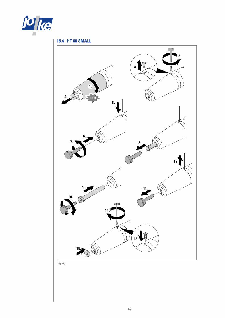
15.4 HT 60 SMALL
CLICK
1.
2.
11.
12.
9.
10.
5.
7.
6.
8.
3.
4.
14.
13.
15.
Fig. 49

4343
15.5 JEHG400/JHG210
1.
2.
6.
5.
3.
4.
Fig. 50
15.6 JEHR 500, JIR 310
1.
2.
3.
6.
7.
4. 5.
Fig. 51

4444
15.7 JERA 270, JBMH 300 N
1.
4.
2.
3.
Fig. 52
15.8 JERA 270 S
1.
2.
6.
5.
3.
4.
Fig. 53

4545
15.9 JIH 300
2.
1.90°
3.
4. 1/5
5.
6.90°
Fig. 54
15.10 JKC 345, JIC 390, JEKC 300, WE4-45, WE4-90
3.
4.
5.
6.
1.
2.
Fig. 55
15.11 JMFC 300 S / 300 M
1.
2. 3.
4.
Fig. 56

4646
16 Maintenance and care
16.1 Safety• Before starting maintenance, it must be ascertained who is permitted to carry out each task.
The individual maintenance tasks may only be carried out by persons authorised to do so.
• If there is any uncertainty as to who may carry out which work, first clarify this with the person who is authorised to decide.
• Before starting maintenance work on components of the unit, always switch off the power supply with the main switch and secure it against being switched on again.
• The rear door of the unit may only be opened by persons who are authorised to do so.
• To avoid dangerous electric shocks, always take care during maintenance work not to damage the earth cables that are attached at various places.
- If necessary, properly disconnect the earth cables and correctly reinstall them after com-pleting the maintenance.
- Properly reconnect disconnected earth cables after changing the filter.
• Allow the components in the cabinet of the unit to cool down before starting work.
• Collect escaping oil and immediately wipe up any that gets onto the floor or components of the unit.
• Collect escaping dust and immediately wipe up any that falls onto the floor or components of the unit.
• Dispose of oil and dust properly.
• Remove dirt from components of the unit with a dry or slightly dampened soft microfibre cloth. A cleaning agent may be used if it will not damage any components.
• Only use genuine JOKE spare parts for necessary repairs.
16.2 Maintenance-free components• Handpieces
• Brushless JOKE motors
16.3 Every day » Maintenance unit
- Check the condensate indicator: If the condensate level has reached the upper mark, drain the condensate. Proceed as described in the manufacturer’s instructions.
» Optional maintenance unit with oiler
- Check how much oil is dispensed: Look in the sight bubble. Guide amount: 2–3 drops of oil per minute. If no drops form, top up the oil. If still no drops are formed or if the drops con-tain air, follow the manufacturer’s instructions.

4747
16.4 Every week » Oil extraction system
Every 20 hours the message "ATTENTION maintenance Clean the collector” on the display indicates that the collector requires maintenance.
- Clean the collector. The procedure is described in Fig. 57. Another sign that the collector needs cleaning is when the extraction system no longer cleans the working chamber as well as it usually does. There may also be excess pressure in the extraction system, which causes the pressure relief valve to open and audibly release air.
- Check all components of the extraction system for damage and leaks. Arrange for repair if necessary.
- After maintenance, acknowledge the service message in the service menu, see section 10.2
» Dry extraction system Every 20 hours the message "ATTENTION maintenance Empty the collector” in the display indicates that the collector requires maintenance.
- Empty the collector. The procedure is described in Fig. 58. Another sign that the collector needs cleaning is when the extraction system no longer cleans the working chamber as well as it usually does. There may also be excess pressure in the extraction system, which causes the pressure relief valve to open and audibly release air.
- Check all components of the extraction system for damage and leaks. Arrange for repair if necessary.
- After maintenance, acknowledge the service message in the service menu, see section 10.2.
» Check the gloves for damage and replace if necessary. » Remove dust deposits and dirt in the working chamber. » Service and maintain carbon brush motors according to the manufacturer’s instructions. » Clean and lightly oil the collets. » Maintenance unit:
- Check all components of the maintenance unit for damage and leaks. If there is any dam-age, contact JOKE customer service.
- Check the oil level. Top up if the oil level is low (1/3 of the maximum filling quantity).
- Drain off any condensate according to the manufacturer’s instructions.

4848
16.5 Every month » Oil extraction system
Every 80 hours the message "ATTENTION maintenance Clean the collector Replace high-performance oil Check wet filter and replace if necessary” on the display indicates that the collector requires maintenance.
- Clean the collector. The procedure is described in Fig. 57.
- Replace the high-performance oil. At the same time, check the wet filter of the collector and replace it if necessary. The procedure is described in section 16.10.
- After maintenance, acknowledge the service message in the service menu, see section 10.2.
» Dry extraction system Every 80 hours the message “ATTENTION maintenance Empty the collector Clean M filter” on the display indicates that the collector requires maintenance.
- Clean the M filter and empty the collector. The procedure is described in Fig. 58.
- After maintenance, acknowledge the service message in the service menu, see section 10.2.
16.6 Every six months and as required » Oil extraction system
Every 500 hours the message “ATTENTION maintenance Clean the collector Replace high-performance oil Check wet filter and replace if necessary Replace filter element in dust measuring device Replace H and M filters” on the display indicates that the collector requires maintenance.
- Clean the collector. The procedure is described in Fig. 57.
- Replace the high-performance oil. At the same time, check the wet filter of the collector and replace it if necessary. The procedure is described in section 16.10.
- Replace the filter element in the dust measuring device. The procedure is described in section 16.9.
- Replace the H filter and the M filter. The procedure is described in section 16.11.1. Another sign that the H and M filters need to be replaced is if the extraction system no longer cleans the working chamber as well as it usually does. There may also be excess pressure in the extraction system, which causes the pressure relief valve to open and audibly release air.
- Check the seals, screws and nuts of the extraction system. If there is any damage, contact JOKE customer service.
- After maintenance, acknowledge the service message in the service menu, see section 10.2

4949
» Oil extraction system Every 500 hours the message “ATTENTION maintenance Empty the collector Replace filter element in dust measuring device Replace H and M filters” on the display indicates that the collector requires maintenance.
- Empty the collector. The procedure is described in Fig. 58.
- Replace the filter element in the dust measuring device. The procedure is described in section 16.9.
- Replace the H filter and the M filter. The procedure is described in section 16.11.2. Another sign that the H and M filters need to be replaced is if the extraction system no longer cleans the working chamber as well as it usually does. There may also be excess pressure in the extraction system, which causes the pressure relief valve to open and audibly release air.
- Check the seals, screws and nuts of the extraction system. If there is any damage, contact JOKE customer service.
- After maintenance, acknowledge the service message in the service menu, see section 10.2.
» Have all electrical material checked by qualified personnel. If there is any damage, contact JOKE customer service.
» Check the maintenance unit for cracks, opacity, leaks and other damage. If there is any dam-age, contact JOKE customer service.
16.7 Every year » Have the ENESKApostpro serviced once a year by JOKE Service.

5050
16.8 Cleaning the collector
6.
5.
4.
1.
3.2.
7.
Fig. 57 Oil extraction
1.
3. 2.
4.
Fig. 58 Dry extraction
» Turn off the power supply with the main switch. » Unlock the rear door of the unit with the key. » Tilt the door without damaging the earth cable. Release and remove the earth cable. Take off
the door. » Clean the collector and its components as shown.
If damage is visible on individual components, replace them with new ones. Remove dust deposits and dirt from the components of the extraction system.
» Properly dispose of dust and collected oil. » Reassemble the collector in the reverse order and connect it to the main filter.
Position the lid on the collector so that the marking arrows on the lid and on the container line up.
» Put the rear door of the unit back on, connect the earth cable and close the door. » Lock the door with the key. » Turn on the power supply with the main switch.

5151
16.9 Replacing the filter element in the dust measuring device
1 2
3 1
4
1.
2.
3.
4. 5.
6.
Fig. 59

5252
16.10 Changing the oil
17.
15.
14.
16.
MAX
13.
7.
8.
9.
10.
11.
12.
5.
4.
3.
1.
2.
6.
Fig. 60

5353
» Turn off the power supply with the main switch. » Unlock the rear door of the unit with the key. » Tilt the door without damaging the earth cable. Release and remove the earth cable. Take off
the door. » Take the extraction system out of the cabinet, drain the oil and clean all the components of the
collector as described in Fig. 60 on page 52. » If damage is visible on individual components, replace them with new ones. » Remove dust deposits and dirt from the components of the extraction system. » Properly dispose of dust and collected oil. » Reinstall all the components of the collector in the reverse order except for the lid. » Fill the collector with new oil up to the “MAX” mark. The mark is located next to the sight
glass. » Position the lid on the collector so that the marking arrows on the lid and on the receptacle
line up. » Reassemble and connect the extraction system in the reverse order. » Put the rear door of the unit back on, connect the earth cable and close the door. » Lock the door with the key. » Turn on the power supply with the main switch.

5454
16.11 Changing the filters
16.11.1 Changing the filters of the oil extraction system
Danger!Explosion hazard from igniting dust!Dust can easily ignite when mixed with oxygen.
• Always take the extraction system to a separate room suitable for working with dust in the atmosphere. Only then start changing the filters.
21. 20.19.
18.
13.
14.
17. 16.
15.
11.
12.
7.
8.
9.
10.
5.
4.
3.
1.
2.
23.
22.
6.
Fig. 61

5555
» Turn off the power supply with the main switch. » Unlock the rear door of the unit with the key. » Tilt the door without damaging the earth cable. Release and remove the earth cable. Take off
the door. » Take the extraction system out of the cabinet as described in Fig. 61 on page 54. » Use a forklift truck to take the extraction system to a separate room suitable for processing
dust » Remove the collector and all the filters of the extraction system, as described in Fig. 61 on
page 54. » Clean all the components of the collector. If damage is visible on individual components,
replace them with new ones. » Remove dust deposits and dirt from the components of the extraction system. » Dispose of all filters, dust and collected oil in the proper manner. » Reinstall all the components of the collector in the reverse order except for the lid. » Fill the collector with new oil up to the “MAX” mark. The mark is located next to the sight
glass. » Position the lid on the collector so that the marking arrows on the lid and on the receptacle
line up. » Reassemble and connect the extraction system with new filters in the reverse order. » Put the rear door of the unit back on, connect the earth cable and close the door. » Lock the door with the key. » Turn on the power supply with the main switch.

5656
16.11.2 Changing the filters of the dry extraction system
Danger!Explosion hazard from igniting dust!Dust can easily ignite when mixed with oxygen.
• Always take the extraction system to a separate room suitable for working with dust in the atmosphere. Only then start changing the filters.
16. 15.14.
13.
8.
9.
12. 11.
10.
5.
4.
3.
1.
2.
18.
17.
7.6.
Fig. 62

5757
» Turn off the power supply with the main switch. » Unlock the rear door of the unit with the key. » Tilt the door without damaging the earth cable. Release and remove the earth cable. Take off
the door. » Remove the extraction system from the cabinet, take it to a separate room and remove the
collector and all the filters of the extraction system as described in Fig. 62 on page 56. » Clean all the components of the collector.
If damage is visible on individual components, replace them with new ones. » Remove dust deposits and dirt from the components of the extraction system. » Dispose of all filters and dust in the proper manner. » Reassemble the collector in the reverse order.
Position the lid of the collector so that the marking arrows on the lid and on the container are in line.
» Reassemble and connect the extraction system with new filters in the reverse order. » Put the rear door of the unit back on, connect the earth cable and close the door. » Lock the door with the key. » Turn on the power supply with the main switch.

5858
17 TroubleshootingFor any problems with the unit not listed here or if you have any questions, contact JOKE cus-tomer service.Only use genuine JOKE spare parts for rectifying faults.
17.1 Problems with the unit controller
Problem Cause RemedyMachine cannot be switched on with the con-troller
• Main switch not turned on • Turn on the main switch.
Error message: compressed air not connected
• Insufficient air flow • Increase the air flow, e.g. by using a larger air supply hose.
• Air pressure too low • Increase the air pressure (at least 3 bar).
• No supply line connected • Connect the supply line.
Flap not closed • Flap not in end position • Remove objects between the flap and the worktable.
• Close the flap completely.

5959
17.2 Problems with the ENESKAmicro motor controllerThe motor controller for the handpieces is equipped with an overload switch. If the overload switch in the control unit has been triggered, it is very likely that the handpiece or micromotor has been continuously operated at maximum load. The motor then stops automatically and cannot be switched on again for a short time. In this case, wait 3–5 seconds and then continue working with less load on the unit.
Problem / error code
Cause Remedy
The display is not lit.
• The power supply is not switched on. • Switch on the power supply, see section 7.1.
• The unit has not been started. • Start the unit, see section 7.5.
• Control unit, cables, connections, contacts or sockets are faulty.
• Send the unit and accessories to JOKE Service for inspection or repair.
The motor will not start.
The tool does not turn.
• The motor or handpiece have been overloaded.
• Stop using the unit and accessories, wait 3–5 seconds, then operate the unit and accessories at a lower load.
• The quick-release lever on the hand-piece is open.
• The quick-release lever on the hand-piece is not closed.
• Fit the tool correctly.
• Close the quick-release lever or quick-re-lease chuck.
• The collet or tool is jammed. • Adjust the collet.
• Fit the tool correctly.
• Contacts are faulty. • Check the motor connections
• Check the connections between the motor and the accessories.
• The carbon brushes are worn out. • Replace the carbon brushes.
• Motor, circuit, cable, connections, contacts or sockets are faulty.
• Send the unit and accessories to JOKE Service for inspection or repair.
E 1 / E3 / E4 / E5 / E6
• Excess current detected • Stop using the unit and accessories, wait 3–5 seconds, then operate the unit and accessories at a lower load.
• Check all components. Have faulty com-ponents repaired.
• Restart the control unit.
• Unroll cables which have been rolled up.
• Send the unit and accessories to JOKE Service for inspection or repair.
E2 Commutation fault • Check and correct the connections be-tween the motor and its accessories.
• Replace faulty cables.
E7 Excess current warning • Minimise the working pressure. Do not subject the unit and its accessories to the maximum load.
E8 Defective controller • Restart the control unit.
• Send the unit or accessories to JOKE Service for inspection or repair.

6060
17.3 Problems with the compressed air supply
Problem Cause RemedyPressure is insufficient or not controlled.
• Defective pressure regulator • Have the pressure regulator replaced by qualified personnel, see the manufactur-er’s instructions.
Condensate is not drained although the condensate drain is acti-vated.
• Dirt particles in the condensate drain. • Have the container replaced by quali-fied personnel, see the manufacturer’s instructions.
Air constantly escapes from the condensate drain.
• Dirt particles in the condensate drain.
• Condensate drain valve damaged.
• Open the condensate drain for a few sec-onds, see the manufacturer’s instructions.
• Have the container replaced by quali-fied personnel, see the manufacturer’s instructions.
17.4 Problems with the extraction system
Problem Cause Remedy
The extraction system does not clean the working chamber as well as it usu-ally does.
• Insufficient fluid level in the collector
• The collector is full.
• One of the main filters is clogged.
• Leaks or blockages in the unit or other parts of the extraction system.
• The extraction pump is clogged, leaking or defective.
• Change the oil in the collector (only for oil extraction, see section 16.10).
• Clean the collector (see section 16.8).
• Change the filter (see section 16.11).
• Check the extraction system components, locks and seals for leaks. Have leaks repaired by JOKE Service.
• Look for blockages in the unit or the ex-traction system. Remove blockages in the working chamber. Have blockages in the extraction system (except clogged filters) removed by JOKE Service.
• Check whether there are any faults with the extraction system pump. If the pump is defective, have it repaired by JOKE Service.
Dust and air escape from the pressure relief valve.
• The collector is full.
• One of the main filters is clogged.
• Blockages in the unit or other parts of the extraction system.
• Clean the collector (see section 16.8).
• Change the filter (see section 16.11).
• Look for blockages in the unit or the ex-traction system. Remove blockages in the working chamber. Have blockages in the extraction system (except blocked filters) removed by the JOKE Service.

6161
18 Repairs
18.1 Changing damaged gloves » Open the clamps on the hand holes. » Remove the gloves. » Pull new gloves on the holders. » Fasten the new gloves to the hand holes with the clamps.
18.2 Replacing a defective lamp » Loosen the screws that secure the lamp to the unit. » Remove the defective lamp from the holder. » Put the new lamp into the holder, align it and fasten it with the screws.
19 Decommissioning » Switch off the unit. » Turn off the main switch. » Disconnect the unit from the power supply. » Disconnect the unit from the compressed air. » Drain condensate and oil from the maintenance unit, see the manufacturer’s instructions. » Clean the collector of the extraction system, see section 16.8.
20 Storage
Attention!Damage due to incorrect storageThe unit may be damaged if it is stored incorrectly.• The storage location must meet the ambient conditions listed in the technical specifications. • The unit may not be stored outdoors. • The floor at the installation site must be able to support the weight of the unit.
» Decommission the unit, see section 19. » Transport the unit to the storage location and put it in a stable position, see chapter 6.1 and
6.2. » Make sure the unit and its accessories are permanently protected from dirt.
21 Recommissioning » Have the recommissioning carried out by JOKE Service.
22 Disposal » Dispose of the unit and accessories in accordance with the legal regulations for disposal of
material and hazardous substances.

6262
23 Declaration of Conformity
Declaration of Conformity in accordance with the Machinery Directive 2006/42/EC, Annex II 1A
Manufacturer: joke Technology GmbH
Asselborner Weg 14 - 16 51429 Bergisch Gladbach, Germany
Product: Designation: Type: Serial number: Function:
Device for reworking additively manufactured components ENESKApostpro The ENESKApostpro is used exclusively for reworking (removal, deburring, separation) of additively manufactured components.
We, joke Technology GmbH, hereby declare that the above-mentioned product complies with the relevant provisions of the Machinery Directive 2006/42/EC. The safety objectives of the Low Voltage Directive 2014/35/EU are complied with in accordance with Annex I, No. 1.5.1 of the Machinery Directive. The following harmonised standards have been applied: • EN ISO 12100:2010 Safety of machinery – General principles for design – Risk assessment and risk
reduction
• EN 60204-1:2014 Safety of machinery – Electrical equipment of machines – Part 1: General requirements
• EN ISO 14120:2016 Safety of machinery – Guards – General requirements for the design and construction of fixed and movable guards
• EN ISO 13849-1:2016 Safety of machinery – Safety-related parts of control systems – Part 1 General principles for design
• EN ISO 13732-1:2008 Ergonomics of the thermal environment – Methods for the assessment of human responses to contact with surfaces – Part 1: Hot surfaces
The following other technical standards/specifications have been applied: - Authorised representative for the compilation of the technical documentation:
Kerstin Otto Asselborner Weg 14 - 16 51429 Bergisch Gladbach, Germany
Bergisch-Gladbach, 17 November 2020
Udo Fielenbach, Managing Director

Surface TechnologyOberflächentechnik
Order number for operating manual: BA2093GB
© Copyright joke Technology GmbH • December 2020 • Subject to changes due to technical progress, errors and misprints • Reproduction, in whole or in part, only with prior written permission.
joke Technology GmbHAsselborner Weg 14 - 1651429 Bergisch Gladbach
GermanyTel. +49 (0) 22 04 / 8 39-0
Fax +49 (0) 22 04 / 8 39-60Mail [email protected]
Web www.joke-technology.com
Brilliant solutions for perfect surfaces