operating manual cts30 - rohde & schwarz · pdf filebefore putting the product into ......
TRANSCRIPT

1094.3434.12-05- 1
Test and Measurement Division
Operating Manual
Digital Radio Tester
for GSM (GSM 900) - PCN (GSM 1800 / DCS 1800) - PCS (GSM 1900 / DCS 1900) - Mobiles
R&S CTS30 1094.0006.30
Printed in Germany

1094.3434.12-05- 2
Dear Customer, R&S® is a registered trademark of Rohde & Schwarz GmbH & Co. KG. Trade names are trademarks of the owners.

CTS30 Tabbed Divider Overview
1094.3434.12 3 E-2
Data Sheet
Safety InstructionsCertificate of qualityEC Certificate of ConformityList of R & S Representatives
1 Introduction ....................................................................................... Tabbed Divider 1
2 Preparation for Use........................................................................ Tabbed Divider 2
3 Remote Control................................................................................ Tabbed Divider 3
Windows Application CTSgo ....................................................................... Tabbed Divider 4
Annexes ................................................................................................................ Tabbed Divider 5
List of Error MessagesList of CommandsMS Power Charts

CTS30 Data Sheet CTS
1094.3434.12-01- A E-2
Supplement to Data Sheet CTS
Technical SpecificationsThe technical specifications and the functions of CTS30 are identical with those given in the CTS datasheet for GSM. However, operation of CTS 30 is controlled by Application Software CTSgo suppliedwith the instrument.


1171.0000.42-02.00 Sheet 1
Before putting the product into operation for the first time, make sure to read the following
S a f e t y I n s t r u c t i o n s
Rohde & Schwarz makes every effort to keep the safety standard of its products up to date and to offer its customers the highest possible degree of safety. Our products and the auxiliary equipment required for them are designed and tested in accordance with the relevant safety standards. Compliance with these standards is continuously monitored by our quality assurance system. This product has been designed and tested in accordance with the EC Certificate of Conformity and has left the manufacturer�s plant in a condition fully complying with safety standards. To maintain this condition and to ensure safe operation, observe all instructions and warnings provided in this manual. If you have any questions regarding these safety instructions, Rohde & Schwarz will be happy to answer them.
Furthermore, it is your responsibility to use the product in an appropriate manner. This product is designed for use solely in industrial and laboratory environments or in the field and must not be used in any way that may cause personal injury or property damage. You are responsible if the product is used for an intention other than its designated purpose or in disregard of the manufacturer's instructions. The manufacturer shall assume no responsibility for such use of the product.
The product is used for its designated purpose if it is used in accordance with its operating manual and within its performance limits (see data sheet, documentation, the following safety instructions). Using the products requires technical skills and knowledge of English. It is therefore essential that the products be used exclusively by skilled and specialized staff or thoroughly trained personnel with the required skills. If personal safety gear is required for using Rohde & Schwarz products, this will be indicated at the appropriate place in the product documentation.
Symbols and safety labels
Observe operating instructions
Weight indication for units >18 kg
Danger of electric shock
Warning! Hot surface
PE terminal Ground Ground terminal
Attention! Electrostatic sensitive devices
Supply voltage ON/OFF
Standby indication
Direct current (DC)
Alternating current (AC)
Direct/alternating current (DC/AC)
Device fully protected by double/reinforced insulation

Safety Instructions
1171.0000.42-02.00 Sheet 2
Observing the safety instructions will help prevent personal injury or damage of any kind caused by dangerous situations. Therefore, carefully read through and adhere to the following safety instructions before putting the product into operation. It is also absolutely essential to observe the additional safety instructions on personal safety that appear in other parts of the documentation. In these safety instructions, the word "product" refers to all merchandise sold and distributed by Rohde & Schwarz, including instruments, systems and all accessories.
Tags and their meaning DANGER This tag indicates a safety hazard with a high potential of risk for the
user that can result in death or serious injuries. WARNING This tag indicates a safety hazard with a medium potential of risk for the
user that can result in death or serious injuries. CAUTION This tag indicates a safety hazard with a low potential of risk for the user
that can result in slight or minor injuries. ATTENTION This tag indicates the possibility of incorrect use that can cause damage
to the product. NOTE This tag indicates a situation where the user should pay special attention
to operating the product but which does not lead to damage. These tags are in accordance with the standard definition for civil applications in the European Economic Area. Definitions that deviate from the standard definition may also exist. It is therefore essential to make sure that the tags described here are always used only in connection with the associated documentation and the associated product. The use of tags in connection with unassociated products or unassociated documentation can result in misinterpretations and thus contribute to personal injury or material damage.
Basic safety instructions 1. The product may be operated only under
the operating conditions and in the positions specified by the manufacturer. Its ventilation must not be obstructed during operation. Unless otherwise specified, the following requirements apply to Rohde & Schwarz products: prescribed operating position is always with the housing floor facing down, IP protection 2X, pollution severity 2, overvoltage category 2, use only in enclosed spaces, max. operation altitude max. 2000 m. Unless specified otherwise in the data sheet, a tolerance of ±10% shall apply to the nominal voltage and of ±5% to the nominal frequency.
2. Applicable local or national safety regulations and rules for the prevention of accidents must be observed in all work performed. The product may be opened only by authorized, specially trained personnel. Prior to performing any work on the product or opening the product, the
product must be disconnected from the supply network. Any adjustments, replacements of parts, maintenance or repair must be carried out only by technical personnel authorized by Rohde & Schwarz. Only original parts may be used for replacing parts relevant to safety (e.g. power switches, power transformers, fuses). A safety test must always be performed after parts relevant to safety have been replaced (visual inspection, PE conductor test, insulation resistance measurement, leakage current measurement, functional test).
3. As with all industrially manufactured goods, the use of substances that induce an allergic reaction (allergens, e.g. nickel) such as aluminum cannot be generally excluded. If you develop an allergic reaction (such as a skin rash, frequent sneezing, red eyes or respiratory difficulties), consult a physician immediately to determine the cause.

Safety Instructions
1171.0000.42-02.00 Sheet 3
4. If products/components are mechanically and/or thermically processed in a manner that goes beyond their intended use, hazardous substances (heavy-metal dust such as lead, beryllium, nickel) may be released. For this reason, the product may only be disassembled, e.g. for disposal purposes, by specially trained personnel. Improper disassembly may be hazardous to your health. National waste disposal regulations must be observed.
5. If handling the product yields hazardous substances or fuels that must be disposed of in a special way, e.g. coolants or engine oils that must be replenished regularly, the safety instructions of the manufacturer of the hazardous substances or fuels and the applicable regional waste disposal regulations must be observed. Also observe the relevant safety instructions in the product documentation.
6. Depending on the function, certain products such as RF radio equipment can produce an elevated level of electromagnetic radiation. Considering that unborn life requires increased protection, pregnant women should be protected by appropriate measures. Persons with pacemakers may also be endangered by electromagnetic radiation. The employer is required to assess workplaces where there is a special risk of exposure to radiation and, if necessary, take measures to avert the danger.
7. Operating the products requires special training and intense concentration. Make certain that persons who use the products are physically, mentally and emotionally fit enough to handle operating the products; otherwise injuries or material damage may occur. It is the responsibility of the employer to select suitable personnel for operating the products.
8. Prior to switching on the product, it must be ensured that the nominal voltage setting on the product matches the nominal voltage of the AC supply network. If a different voltage is to be set, the power fuse of the product may have to be changed accordingly.
9. In the case of products of safety class I with movable power cord and connector, operation is permitted only on sockets with earthing contact and protective earth connection.
10. Intentionally breaking the protective earth connection either in the feed line or in the product itself is not permitted. Doing so can result in the danger of an electric shock from the product. If extension cords or connector strips are implemented, they must be checked on a regular basis to ensure that they are safe to use.
11. If the product has no power switch for disconnection from the AC supply, the plug of the connecting cable is regarded as the disconnecting device. In such cases, it must be ensured that the power plug is easily reachable and accessible at all times (length of connecting cable approx. 2 m). Functional or electronic switches are not suitable for providing disconnection from the AC supply. If products without power switches are integrated in racks or systems, a disconnecting device must be provided at the system level.
12. Never use the product if the power cable is damaged. By taking appropriate safety measures and carefully laying the power cable, ensure that the cable cannot be damaged and that no one can be hurt by e.g. tripping over the cable or suffering an electric shock.
13. The product may be operated only from TN/TT supply networks fused with max. 16 A.
14. Do not insert the plug into sockets that are dusty or dirty. Insert the plug firmly and all the way into the socket. Otherwise this can result in sparks, fire and/or injuries.
15. Do not overload any sockets, extension cords or connector strips; doing so can cause fire or electric shocks.
16. For measurements in circuits with voltages Vrms > 30 V, suitable measures (e.g. appropriate measuring equipment, fusing, current limiting, electrical separation, insulation) should be taken to avoid any hazards.
17. Ensure that the connections with information technology equipment comply with IEC 950/EN 60950.
18. Never remove the cover or part of the housing while you are operating the product. This will expose circuits and components and can lead to injuries, fire or damage to the product.

Safety Instructions
1171.0000.42-02.00 Sheet 4
19. If a product is to be permanently installed, the connection between the PE terminal on site and the product's PE conductor must be made first before any other connection is made. The product may be installed and connected only by a skilled electrician.
20. For permanently installed equipment without built-in fuses, circuit breakers or similar protective devices, the supply circuit must be fused in such a way that suitable protection is provided for users and products.
21. Do not insert any objects into the openings in the housing that are not designed for this purpose. Never pour any liquids onto or into the housing. This can cause short circuits inside the product and/or electric shocks, fire or injuries.
22. Use suitable overvoltage protection to ensure that no overvoltage (such as that caused by a thunderstorm) can reach the product. Otherwise the operating personnel will be endangered by electric shocks.
23. Rohde & Schwarz products are not protected against penetration of water, unless otherwise specified (see also safety instruction 1.). If this is not taken into account, there exists the danger of electric shock or damage to the product, which can also lead to personal injury.
24. Never use the product under conditions in which condensation has formed or can form in or on the product, e.g. if the product was moved from a cold to a warm environment.
25. Do not close any slots or openings on the product, since they are necessary for ventilation and prevent the product from overheating. Do not place the product on soft surfaces such as sofas or rugs or inside a closed housing, unless this is well ventilated.
26. Do not place the product on heat-generating devices such as radiators or fan heaters. The temperature of the environment must not exceed the maximum temperature specified in the data sheet.
27. Batteries and storage batteries must not be exposed to high temperatures or fire. Keep batteries and storage batteries away from children. If batteries or storage batteries are improperly replaced, this can cause an explosion (warning: lithium cells). Replace the battery or storage battery only with the
matching Rohde & Schwarz type (see spare parts list). Batteries and storage batteries are hazardous waste. Dispose of them only in specially marked containers. Observe local regulations regarding waste disposal. Do not short-circuit batteries or storage batteries.
28. Please be aware that in the event of a fire, toxic substances (gases, liquids etc.) that may be hazardous to your health may escape from the product.
29. Please be aware of the weight of the product. Be careful when moving it; otherwise you may injure your back or other parts of your body.
30. Do not place the product on surfaces, vehicles, cabinets or tables that for reasons of weight or stability are unsuitable for this purpose. Always follow the manufacturer's installation instructions when installing the product and fastening it to objects or structures (e.g. walls and shelves).
31. Handles on the products are designed exclusively for personnel to hold or carry the product. It is therefore not permissible to use handles for fastening the product to or on means of transport such as cranes, fork lifts, wagons, etc. The user is responsible for securely fastening the products to or on the means of transport and for observing the safety regulations of the manufacturer of the means of transport. Noncompliance can result in personal injury or material damage.
32. If you use the product in a vehicle, it is the sole responsibility of the driver to drive the vehicle safely. Adequately secure the product in the vehicle to prevent injuries or other damage in the event of an accident. Never use the product in a moving vehicle if doing so could distract the driver of the vehicle. The driver is always responsible for the safety of the vehicle; the manufacturer assumes no responsibility for accidents or collisions.
33. If a laser product (e.g. a CD/DVD drive) is integrated in a Rohde & Schwarz product, do not use any other settings or functions than those described in the documentation. Otherwise this may be hazardous to your health, since the laser beam can cause irreversible damage to your eyes. Never try to take such products apart, and never look into the laser beam.

1171.0000.42-02.00 página 1
Por favor lea imprescindiblemente antes de la primera puesta en funcionamiento las siguientes informaciones de seguridad
Informaciones de seguridad
Es el principio de Rohde & Schwarz de tener a sus productos siempre al día con los estandards de seguridad y de ofrecer a sus clientes el máximo grado de seguridad. Nuestros productos y todos los equipos adicionales son siempre fabricados y examinados según las normas de seguridad vigentes. Nuestra sección de gestión de la seguridad de calidad controla constantemente que sean cumplidas estas normas. Este producto ha sido fabricado y examinado según el comprobante de conformidad adjunto según las normas de la CE y ha salido de nuestra planta en estado impecable según los estandards técnicos de seguridad. Para poder preservar este estado y garantizar un funcionamiento libre de peligros, deberá el usuario atenerse a todas las informaciones, informaciones de seguridad y notas de alerta. Rohde&Schwarz está siempre a su disposición en caso de que tengan preguntas referentes a estas informaciones de seguridad.
Además queda en la responsabilidad del usuario utilizar el producto en la forma debida. Este producto solamente fue elaborado para ser utilizado en la indústria y el laboratorio o para fines de campo y de ninguna manera deberá ser utilizado de modo que alguna persona/cosa pueda ser dañada. El uso del producto fuera de sus fines definidos o despreciando las informaciones de seguridad del fabricante queda en la responsabilidad del usuario. El fabricante no se hace en ninguna forma responsable de consecuencias a causa del maluso del producto.
Se parte del uso correcto del producto para los fines definidos si el producto es utilizado dentro de las instrucciones del correspondiente manual del uso y dentro del margen de rendimiento definido (ver hoja de datos, documentación, informaciones de seguridad que siguen). El uso de los productos hace necesarios conocimientos profundos y el conocimiento del idioma inglés. Por eso se deberá tener en cuenta de exclusivamente autorizar para el uso de los productos a personas péritas o debidamente minuciosamente instruidas con los conocimientos citados. Si fuera necesaria indumentaria de seguridad para el uso de productos de R&S, encontrará la información debida en la documentación del producto en el capítulo correspondiente.
Símbolos y definiciones de seguridad
Ver manual de instrucciones del uso
Informaciones para maquinaria con uns peso de > 18kg
Peligro de golpe de corriente
¡Advertencia! Superficie caliente
Conexión a conductor protector
Conexión a tierra
Conexión a masa conductora
¡Cuidado! Elementos de construción con peligro de carga electroestática
potencia EN MARCHA/PARADA
Indicación Stand-by
Corriente continua DC
Corriente alterna AC
Corriente continua/alterna DC/AC
El aparato está protegido en su totalidad por un aislamiento de doble refuerzo

Informaciones de seguridad
1171.0000.42-02.00 página 2
Tener en cuenta las informaciones de seguridad sirve para tratar de evitar daños y peligros de toda clase. Es necesario de que se lean las siguientes informaciones de seguridad concienzudamente y se tengan en cuenta debidamente antes de la puesta en funcionamiento del producto. También deberán ser tenidas en cuenta las informaciones para la protección de personas que encontrarán en otro capítulo de esta documentación y que también son obligatorias de seguir. En las informaciones de seguridad actuales hemos juntado todos los objetos vendidos por Rohde&Schwarz bajo la denominación de �producto�, entre ellos también aparatos, instalaciones así como toda clase de accesorios.
Palabras de señal y su significado PELIGRO Indica un punto de peligro con gran potencial de riesgo para el
ususario.Punto de peligro que puede llevar hasta la muerte o graves heridas.
ADVERTENCIA Indica un punto de peligro con un protencial de riesgo mediano para el usuario. Punto de peligro que puede llevar hasta la muerte o graves heridas .
ATENCIÓN Indica un punto de peligro con un protencial de riesgo pequeño para el usuario. Punto de peligro que puede llevar hasta heridas leves o pequeñas
CUIDADO Indica la posibilidad de utilizar mal el producto y a consecuencia dañarlo.
INFORMACIÓN Indica una situación en la que deberían seguirse las instrucciones en el uso del producto, pero que no consecuentemente deben de llevar a un daño del mismo.
Las palabras de señal corresponden a la definición habitual para aplicaciones civiles en el ámbito de la comunidad económica europea. Pueden existir definiciones diferentes a esta definición. Por eso se debera tener en cuenta que las palabras de señal aquí descritas sean utilizadas siempre solamente en combinación con la correspondiente documentación y solamente en combinación con el producto correspondiente. La utilización de las palabras de señal en combinación con productos o documentaciones que no les correspondan puede llevar a malinterpretaciones y tener por consecuencia daños en personas u objetos.
Informaciones de seguridad elementales 1. El producto solamente debe ser utilizado
según lo indicado por el fabricante referente a la situación y posición de funcionamiento sin que se obstruya la ventilación. Si no se convino de otra manera, es para los productos R&S válido lo que sigue: como posición de funcionamiento se define principialmente la posición con el suelo de la caja para abajo , modo de protección IP 2X, grado de suciedad 2, categoría de sobrecarga eléctrica 2, utilizar solamente en estancias interiores, utilización hasta 2000 m sobre el nivel del mar. A menos que se especifique otra cosa en la hoja de datos, se aplicará una tolerancia de ±10% sobre el voltaje nominal y de ±5% sobre la frecuencia nominal.
2. En todos los trabajos deberán ser tenidas en cuenta las normas locales de seguridad de trabajo y de prevención de accidentes. El producto solamente debe de ser abierto por personal périto autorizado. Antes de efectuar trabajos en el producto o abrirlo deberá este ser desconectado de la corriente. El ajuste, el cambio de partes, la manutención y la reparación deberán ser solamente efectuadas por electricistas autorizados por R&S. Si se reponen partes con importancia para los aspectos de seguridad (por ejemplo el enchufe, los transformadores o los fusibles), solamente podrán ser sustituidos por partes originales. Despues de cada recambio de partes elementales para la seguridad deberá ser efectuado un control de

Informaciones de seguridad
1171.0000.42-02.00 página 3
seguridad (control a primera vista, control de conductor protector, medición de resistencia de aislamiento, medición de medición de la corriente conductora, control de funcionamiento).
3. Como en todo producto de fabricación industrial no puede ser excluido en general de que se produzcan al usarlo elementos que puedan generar alergias, los llamados elementos alergénicos (por ejemplo el níquel). Si se producieran en el trato con productos R&S reacciones alérgicas, como por ejemplo urticaria, estornudos frecuentes, irritación de la conjuntiva o dificultades al respirar, se deberá consultar inmediatamente a un médico para averigurar los motivos de estas reacciones.
4. Si productos / elementos de construcción son tratados fuera del funcionamiento definido de forma mecánica o térmica, pueden generarse elementos peligrosos (polvos de sustancia de metales pesados como por ejemplo plomo, berilio, níquel). La partición elemental del producto, como por ejemplo sucede en el tratamiento de materias residuales, debe de ser efectuada solamente por personal especializado para estos tratamientos. La partición elemental efectuada inadecuadamente puede generar daños para la salud. Se deben tener en cuenta las directivas nacionales referentes al tratamiento de materias residuales.
5. En el caso de que se produjeran agentes de peligro o combustibles en la aplicación del producto que debieran de ser transferidos a un tratamiento de materias residuales, como por ejemplo agentes refrigerantes que deben ser repuestos en periodos definidos, o aceites para motores, deberan ser tenidas en cuenta las prescripciones de seguridad del fabricante de estos agentes de peligro o combustibles y las regulaciones regionales para el tratamiento de materias residuales. Cuiden también de tener en cuenta en caso dado las prescripciones de seguridad especiales en la descripción del producto.
6. Ciertos productos, como por ejemplo las instalaciones de radiación HF, pueden a causa de su función natural, emitir una radiación electromagnética aumentada. En vista a la protección de la vida en desarrollo deberían ser protegidas personas embarazadas debidamente. También las personas con un bypass pueden correr
peligro a causa de la radiación electromagnética. El empresario está comprometido a valorar y señalar areas de trabajo en las que se corra un riesgo de exposición a radiaciones aumentadas de riesgo aumentado para evitar riesgos.
7. La utilización de los productos requiere instrucciones especiales y una alta concentración en el manejo. Debe de ponerse por seguro de que las personas que manejen los productos estén a la altura de los requerimientos necesarios referente a sus aptitudes físicas, psíquicas y emocionales, ya que de otra manera no se pueden excluir lesiones o daños de objetos. El empresario lleva la responsabilidad de seleccionar el personal usuario apto para el manejo de los productos.
8. Antes de la puesta en marcha del producto se deberá tener por seguro de que la tensión preseleccionada en el producto equivalga a la del la red de distribución. Si es necesario cambiar la preselección de la tensión también se deberán en caso dabo cambiar los fusibles correspondientes del prodcuto.
9. Productos de la clase de seguridad I con alimentación móvil y enchufe individual de producto solamente deberán ser conectados para el funcionamiento a tomas de corriente de contacto de seguridad y con conductor protector conectado.
10. Queda prohibida toda clase de interrupción intencionada del conductor protector, tanto en la toma de corriente como en el mismo producto ya que puede tener como consecuencia el peligro de golpe de corriente por el producto. Si se utilizaran cables o enchufes de extensión se deberá poner al seguro, que es controlado su estado técnico de seguridad.
11. Si el producto no está equipado con un interruptor para desconectarlo de la red, se deberá considerar el enchufe del cable de distribución como interruptor. En estos casos deberá asegurar de que el enchufe sea de fácil acceso y nabejo (medida del cable de distribución aproximadamente 2 m). Los interruptores de función o electrónicos no son aptos para el corte de la red eléctrica. Si los productos sin interruptor están integrados en construciones o instalaciones, se deberá instalar el interruptor al nivel de la instalación.
Informaciones de seguridad
1171.0000.42-02.00 página 4
12. No utilice nunca el producto si está dañado el cable eléctrico. Asegure a través de las medidas de protección y de instalación adecuadas de que el cable de eléctrico no pueda ser dañado o de que nadie pueda ser dañado por él, por ejemplo al tropezar o por un golpe de corriente.
13. Solamente está permitido el funcionamiento en redes de distribución TN/TT aseguradas con fusibles de como máximo 16 A.
14. Nunca conecte el enchufe en tomas de corriente sucias o llenas de polvo. Introduzca el enchufe por completo y fuertemente en la toma de corriente. Si no tiene en consideración estas indicaciones se arriesga a que se originen chispas, fuego y/o heridas.
15. No sobrecargue las tomas de corriente, los cables de extensión o los enchufes de extensión ya que esto pudiera causar fuego o golpes de corriente.
16. En las mediciones en circuitos de corriente con una tensión de entrada de Ueff > 30 V se deberá tomar las precauciones debidas para impedir cualquier peligro (por ejemplo medios de medición adecuados, seguros, limitación de tensión, corte protector, aislamiento etc.).
17. En caso de conexión con aparatos de la técnica informática se deberá tener en cuenta que estos cumplan los requisitos de la EC950/EN60950.
18. Nunca abra la tapa o parte de ella si el producto está en funcionamiento. Esto pone a descubierto los cables y componentes eléctricos y puede causar heridas, fuego o daños en el producto.
19. Si un producto es instalado fijamente en un lugar, se deberá primero conectar el conductor protector fijo con el conductor protector del aparato antes de hacer cualquier otra conexión. La instalación y la conexión deberán ser efecutadas por un electricista especializado.
20. En caso de que los productos que son instalados fijamente en un lugar sean sin protector implementado, autointerruptor o similares objetos de protección, deberá la toma de corriente estar protegida de manera que los productos o los usuarios estén suficientemente protegidos.
21. Por favor, no introduzca ningún objeto que no esté destinado a ello en los orificios de la caja del aparato. No vierta nunca ninguna clase de líquidos sobre o en la caja. Esto puede producir corto circuitos en el producto y/o puede causar golpes de corriente, fuego o heridas.
22. Asegúrese con la protección adecuada de que no pueda originarse en el producto una sobrecarga por ejemplo a causa de una tormenta. Si no se verá el personal que lo utilice expuesto al peligro de un golpe de corriente.
23. Los productos R&S no están protegidos contra el agua si no es que exista otra indicación, ver también punto 1. Si no se tiene en cuenta esto se arriesga el peligro de golpe de corriente o de daños en el producto lo cual también puede llevar al peligro de personas.
24. No utilice el producto bajo condiciones en las que pueda producirse y se hayan producido líquidos de condensación en o dentro del producto como por ejemplo cuando se desplaza el producto de un lugar frío a un lugar caliente.
25. Por favor no cierre ninguna ranura u orificio del producto, ya que estas son necesarias para la ventilación e impiden que el producto se caliente demasiado. No pongan el producto encima de materiales blandos como por ejemplo sofás o alfombras o dentro de una caja cerrada, si esta no está suficientemente ventilada.
26. No ponga el producto sobre aparatos que produzcan calor, como por ejemplo radiadores o calentadores. La temperatura ambiental no debe superar la temperatura máxima especificada en la hoja de datos.

Informaciones de seguridad
1171.0000.42-02.00 página 5
27. Baterías y acumuladores no deben de ser expuestos a temperaturas altas o al fuego. Guardar baterías y acumuladores fuera del alcance de los niños. Si las baterías o los acumuladores no son cambiados con la debida atención existirá peligro de explosión (atención celulas de Litio). Cambiar las baterías o los acumuladores solamente por los del tipo R&S correspondiente (ver lista de piezas de recambio). Baterías y acumuladores son deshechos problemáticos. Por favor tirenlos en los recipientes especiales para este fín. Por favor tengan en cuenta las prescripciones nacionales de cada país referente al tratamiento de deshechos. Nunca sometan las baterías o acumuladores a un corto circuito.
28. Tengan en consideración de que en caso de un incendio pueden escaparse gases tóxicos del producto, que pueden causar daños a la salud.
29. Por favor tengan en cuenta que en caso de un incendio pueden desprenderse del producto agentes venenosos (gases, líquidos etc.) que pueden generar daños a la salud.
30. No sitúe el producto encima de superficies, vehículos, estantes o mesas, que por sus características de peso o de estabilidad no sean aptas para él. Siga siempre las instrucciones de instalación del fabricante cuando instale y asegure el producto en objetos o estructuras (por ejemplo paredes y estantes).
31. Las asas instaladas en los productos sirven solamente de ayuda para el manejo que solamente está previsto para personas. Por eso no está permitido utilizar las asas para la sujecion en o sobre medios de transporte como por ejemplo grúas, carretillas elevadoras de horquilla, carros etc. El usuario es responsable de que los productos sean sujetados de forma segura a los medios de transporte y de que las prescripciones de seguridad del fabricante de los medios de transporte sean tenidas en cuenta. En caso de que no se tengan en cuenta pueden causarse daños en personas y objetos.
32. Si llega a utilizar el producto dentro de un vehículo, queda en la responsabilidad absoluta del conductor que conducir el vehículo de manera segura. Asegure el producto dentro del vehículo debidamente para evitar en caso de un accidente las lesiones u otra clase de daños. No utilice nunca el producto dentro de un vehículo en movimiento si esto pudiera distraer al conductor. Siempre queda en la responsabilidad absoluta del conductor la seguridad del vehículo y el fabricante no asumirá ninguna clase de responsabilidad por accidentes o colisiones.
33. Dado el caso de que esté integrado un producto de laser en un producto R&S (por ejemplo CD/DVD-ROM) no utilice otras instalaciones o funciones que las descritas en la documentación. De otra manera pondrá en peligro su salud, ya que el rayo laser puede dañar irreversiblemente sus ojos. Nunca trate de descomponer estos productos. Nunca mire dentro del rayo laser.


1094.0006.30 CE E-2
EC Certificate of Conformity
Certificate No.: 98121
This is to certify that:
Equipment type Order No. Designation
CTS30 1094.0006.30 Digital Radio Tester
complies with the provisions of the Directive of the Council of the European Union on theapproximation of the laws of the Member States
- relating to electrical equipment for use within defined voltage limits(73/23/EEC revised by 93/68/EEC)
- relating to electromagnetic compatibility(89/336/EEC revised by 91/263/EEC, 92/31/EEC, 93/68/EEC)
Conformity is proven by compliance with the following standards:
EN61010-1 : 1993 + A2 : 1995EN50081-1 : 1992EN50082-2 : 1995
Affixing the EC conformity mark as from 1998
ROHDE & SCHWARZ GmbH & Co. KGMühldorfstr. 15, D-81671 München
Munich, 1998-12-17 Central Quality Management FS-QZ / Becker


CTS30 Introduction
1094.0006.30 1.1 E-2
1 Introduction
Tester CTS is a value-for-money instrument for function tests, as well as detailed service testing ondigital mobiles. These tests are performed using a personal computer.
Application Software CTSgo is supplied with the tester.
The CTSgo program comes in two versions.
• CTSgo for Windows 3.1 / Windows 3.11 for Workgroups• CTSgo for Windows 95 / 98 / NT 4.0
The program may be installed in German or English as desired.
For detailed instructions regarding the operation of this program see chapter "Windows ApplicationCTSgo" (Tabbed Divider 4).
Preconditions for System Use
To ensure unimpaired function of CTSgo, your system should meet the following basic requirements.For a more convenient use of CTSgo, particularly the presentation of measurement reports, theemployed graphics card should have a better resolution than the one specified below.
Platform: Windows 3.1 / Windows 3.11 for WorkgroupsProcessor: 486DX2/66 MHzRAM: 8 MbytesDisplay: VGA 640 x 480 pixelsFixed-disk storage: 5 MbytesPeripherals: Mouse, one free serial interface
Platform: Windows 95 / Windows 98 / Windows NT 4.0Processor Pentium 75RAM: 16 MbytesDisplay: VGA 640 x 480 pixelsFixed-disk storage: 5 MbytesPeripherals: Mouse, one free serial interface


CTS30 Putting into Operation
1094.0006.30 2.1 E-5
2 Preparation for Use
When unpacking the instrument, don't forget the items and accessories which are included.
When transporting the instrument in future it is strongly recommended that the protective caps included in the shipping box for protection of the front and rear panel are used. This serves to prevent damage to the protruding items on the front and rear panels.
Important note:
A battery-backed CMOS-RAM retains the data of the setup as well as the complete instrument settings after switch-off.
We recommend to check the lithium battery every one to two years.

Putting into Operation CTS30
1094.0006.30 2.2 E-5
2.1 Explanation of Front and Rear View
This page shows the front and rear view of the instrument, with short explanations on the controls and connectors.
DIGITAL RADIO TESTER
MADE IN GERMANY
RF OUT 2 GSM
RF IN / OUT GSM
INPUT POWER LIMITED
50
50
CTS 30 1094.0006.30
High level outputfor GSM
RF input / output for directcable connection and forconnection of the mobilevia antenna coupler
The input power may not exceed +45 dBm in pulsed mode (1:8)and +39 dBm (8 W) in CW mode! LED (Power ON)
Instrument with input voltage selector
0MONITOR
RS 232
PRINTER
KEYBOARD
100 ... 120 V / 135 VA200 ... 240 V / 160 VA 50 ... 60 Hz
CE
CE
Fan of power supply unit(controlled)
Service connector(e. g. for ext. monitor)
Power switch on/off
Fan(uncontrolled)
Keyboard connector(for an externalkeyboard)
Printer connector for test report
RS232 interface(e. g. for software update,servicing, remote control)
Voltage selector switch
AC supply connectorfor voltage/current supply

CTS30 Putting into Operation
1094.0006.30 2.3 E-5
Instrument with wide-range voltage input
0MONITOR
RS 232
PRINTER
KEYBOARD
100 ... 240 V / 160 VA 50 ... 60 Hz
CE
CE
Fan of power supply unit(controlled)
Service connector(e. g. for ext. monitor)
Power switch on/off
Fan(uncontrolled)
Keyboard connector(for an externalkeyboard)
Printer connector for test report
RS232 interface(e. g. for software update,servicing, remote control)
AC supply connectorfor voltage/current supply

Putting into Operation CTS30
1094.0006.30 2.4 E-5
2.2 Commissioning
2.2.1 Setting up the Instrument
For convenient operation of the instrument note the following:
• Do not cover the ventilation openings! • Ambient temperature +5 to +40 °C. • Avoid moisture and condensation, if it occurs however, the instrument must be thoroughly dried
before switching on. 2.2.2 Connecting the Instrument to the AC Supply
Check the position of the voltage selector and set it to the local AC supply voltage if necessary.
Ø Plug the supplied power cable into the rear power connector and connect the CTS to the power supply.
Instrument with input voltage selector
100...125 V / 0.6 A 200...240 V / 0.3 A 50...60 Hz
Instrument with wide-range voltage input
100 ... 240 V / 160 VA50 ... 60 Hz

CTS30 Putting into Operation
1094.0006.30 2.5 E-5
2.2.3 Connecting the Instrument to the Personal Computer Connect the RS232 serial interface of CTS (rear panel) to the serial interface of your personal computer using the cable supplied (the installation of the CTSgo software is described in detail in chapter 3 of the manual for Windows Application CTSgo). Switch on the CTS (power switch on its rear panel) and your PC. The LED on the CTS front panel lights to show that CTS is ready for operation. 2.2.4 Ensuring Electromagnetic Compliance (EMC) In order to avoid electromagnetic interference, the instrument may only be operated with all covers in place as they form part of the shielding for the instrument. Only appropriate shielded signal and control cables (e.g. RF connecting cables) should be used. 2.2.5 OCXO Reference Oscillator (Option CTS-B1) If your instrument is equipped with this option, be aware that an OCXO needs approximately 15 minutes to warm up after switching on the instrument to achieve full precision.


CTS30 Contents
1094.3434.12 5 E-2
Contents
3 Remote Control .......................................................................................................................... 3.1
3.1 Introduction .............................................................................................................................. 3.1
3.2 Brief Instructions ..................................................................................................................... 3.1
3.3 Switchover to Remote Control ............................................................................................... 3.2
3.4 Device Messages (Commands and Device Responses) ...................................................... 3.2
3.5 Structure and Syntax of the Device Messages ..................................................................... 3.3
3.5.1 SCPI Introduction .......................................................................................................... 3.3
3.5.2 Structure of a Command ............................................................................................... 3.3
3.5.3 Structure of a Command Line ....................................................................................... 3.5
3.5.4 Responses to Queries................................................................................................... 3.7
3.5.5 Parameters.................................................................................................................... 3.8
3.5.6 Overview of Syntax Elements...................................................................................... 3.10
3.6 Description of Commands .................................................................................................... 3.11
3.6.1 Notation ....................................................................................................................... 3.11
3.6.2 Common Commands .................................................................................................. 3.13
3.7 Instrument Model and Command Processing..................................................................... 3.16
3.8 Status Reporting System ...................................................................................................... 3.17
3.8.1 Structure of an SCPI Status Register.......................................................................... 3.17
3.8.2 Overview of the Status Registers ................................................................................ 3.19
3.8.3 Description of the Status Registers ............................................................................. 3.20
3.8.3.1 Status Byte (STB) and Service Request Enable Register (SRE) ................ 3.203.8.3.2 Event-Status-Reg. (ESR) and Event-Status-Enable-Reg. (ESE) ................ 3.21
3.8.4 Error-Queue Query...................................................................................................... 3.22
3.8.5 Resetting Values of the Status Reporting System ...................................................... 3.22

CTS30 Remote Control
1094.0006.30 3.1 E-2
3 Remote Control
3.1 Introduction
The instrument is equipped with a serial interface (RS 232-C). The connector is located at the rear ofthe instrument and permits to connect a controller for remote control. The instrument supports the SCPIversion 1992.0 (Standard Commands for Programmable Instruments). The SCPI standard is based onstandard IEEE 488.2 and aims at the standardization of device-specific commands, error handling andthe status registers (see Section 3.5.1).
This section assumes basic knowledge of SCPI conform programming and operation of the controller. Adescription of the interface commands is to be obtained from the relevant manuals.The requirements of the SCPI standard placed on command syntax, error handling and configuration ofthe status registers are explained in detail in the respective sections. Tables provide a fast overview ofthe commands implemented in the instrument and the bit assignment in the status registers. The tablesare supplemented by a comprehensive description of every command and the status registers.
3.2 Brief Instructions
The short and simple operating sequence given below permits fast putting into operation of theinstrument and setting of its basic functions.
1. Connect CTS and controller using a serial cable (see section 3.1 and annex A).
2. Use a terminal emulation on the controller with the same paramters, as configured on the CTS.For example 9600 baud, no parity, 8 bits, 1 stop bit and hardware-handshake.The character strings must be terminated by a delimiter (linefeed).
3. Send the following strings to the CTS:
"CONF:NETW GSM <LF>""PROC:SEL MAN <LF>" Choose Manual test
The CTS then performs a location update if a mobile is connected and is ready to set up a call with thismobile.
4. To return to manual control, press any key at the front panel.

Remote Control CTS30
1094.0006.30 3.2 E-2
3.3 Switchover to Remote Control
On power-on, the instrument is always in the manual operating state ("LOCAL" state) and can beoperated via the front panel. It is switched to remote control ("REMOTE" state) as soon as it receives acommand from a controller. During remote control, operation via the front panel is disabled. Theinstrument remains in the remote state until it is reset to the manual state via pressing the key "MENUUP". Switching from manual operation to remote control and vice versa does not affect the instrumentsettings.
Indications during Remote Control
In the REMOTE state, the display at the CTS can be configured:
1. Nothing is indicated on the display to increase the speed.
2. The actual remote command, the state of the testset and possibly occured errors are shown.
3. The display changes to the selected menu in a fullscreen-view.
3.4 Device Messages (Commands and Device Responses)
– Commands are messages the controller sends to the instrument. They operate the devicefunctions and request information.The commands are subdivided according to two criteria:
1. According to the effect they have on the instrument:
Setting commands cause instrument settings such as reset of theinstrument or setting the output level to 1 volt.
Queries cause data to be provided for output on the remote-control interface, e.g. for identification of the device orpolling the active input.
2. According to their definition in standard IEEE 488.2:
Common Commands are exactly defined as to their function andnotation in standard IEEE 488.2. They refer tofunctions such as management of the standar-dizedstatus registers, reset and selftest.
Device-specificcommands refer to functions depending on the features of the
instrument such as frequency setting. A majority ofthese commands has also been standar-dized bythe SCPI committee (cf. Section 3.5.1).
– Device responses are messages the instrument sends to the controller after a query. They cancontain measurement results, instrument settings and information on theinstrument status (cf. Section 3.5.4).
Structure and syntax of the device messages are described in Section 3.5. The commands are listedand explained in detail in Section 3.6.
CTS30 Remote Control
1094.0006.30 3.3 E-2
3.5 Structure and Syntax of the Device Messages
3.5.1 SCPI Introduction
SCPI (Standard Commands for Programmable Instruments) describes a standard command set forprogramming instruments, irrespective of the type of instrument or manufacturer. The goal of the SCPIconsortium is to standardize the device-specific commands to a large extent. For this purpose, a modelwas developed which defines the same functions inside a device or for different devices. Commandsystems were generated which are assigned to these functions. Thus it is possible to address the samefunctions with identical commands. The command systems are of a hierarchical structure. Fig. 3-1illustrates this tree structure using a section of command system SOURce, which operates the signalsources of the devices. The other examples concerning syntax and structure of the commands arederived from this command system.SCPI is based on standard IEEE 488.2, i.e. it uses the same syntactic basic elements as well as thecommon commands defined in this standard. Part of the syntax of the device responses is defined withgreater restrictions than in standard IEEE 488.2 (see Section 3.5.4, Responses to Queries).
3.5.2 Structure of a Command
The commands consist of a so-called header and, in most cases, one or more parameters. Header andparameter are separated by a "white space" (ASCII code 0 to 9, 11 to 32 decimal, e.g. blank). Theheaders may consist of several key words. Queries are formed by directly appending a question mark tothe header.
Note: The commands of the SOURCE system used in the following examples are notimplemented in the CTS.
Common commands Common commands consist of a header preceded by an asterisk "*"and one or several parameters, if any.
Examples: *RST RESET, resets the device*ESE 253 EVENT STATUS ENABLE, sets the bits of
the event status enable register*ESR? EVENT STATUS QUERY, queries the
contents of the event status register.
Device-specific commands
Hierarchy: Device-specific commands are of hierarchical structure (see Fig. 3-1).The different levels are represented by combined headers. Headers ofthe highest level (root level) have only one key word. This key worddenotes a complete command system.
Example: SOURce This key word denotes the command systemSOURce.
For commands of lower levels, the complete path has to be specified,starting on the left with the highest level, the individual key words beingseparated by a colon ":".
Example: SOURce:FM:EXTernal:COUPling AC
This command lies in the fourth level of the SOURce system. It sets thecoupling of the external signal source to AC.

Remote Control CTS30
1094.0006.30 3.4 E-2
SOURce
POWer AM FM
MODE INTernal EXTernal STATePOLarity
POLarity COUPling
Fig. 3-1 Tree structure of the SCPI command systems using the SOURce system by way of example
Some key words occur in several levels within one command system. Theireffect depends on the structure of the command, that is to say, at whichposition in the header of a command they are inserted.
Example: SOURce:FM:POLarity NORMalThis command contains key word POLarity in the thirdcommand level. It defines the polarity between modulator andmodulation signal.
SOURce:FM:EXTernal:POLarity NORMalThis command contains key word POLarity in the fourthcommand level. It defines the polarity between modulationvoltage and the resulting direction of the modulation only for theexternal signal source indicated.
Optional key words: Some command systems permit certain key words to be optionally insertedinto the header or omitted. These key words are marked by squarebrackets in the description. The full command length must be recognizedby the instrument for reasons of compatibility with the SCPI standard.Some commands are considerably shortened by these optional key words.
Example: [SOURce]:POWer[:LEVel][:IMMediate]:OFFSet 1This command immediately sets the offset of the signal to 1volt. The following command has the same effect:POWer:OFFSet 1
Note: An optional key word must not be omitted if its effect is specifiedin detail by a numeric suffix.

CTS30 Remote Control
1094.0006.30 3.5 E-2
Long and short form: The key words feature a long form and a short form. Either the short formor the long form can be entered, other abbreviations are not permissible.
Example: STATus:QUEStionable:ENABle 1= STAT:QUES:ENAB 1
Note: The short form is marked by upper-case letters, the long formcorresponds to the complete word. Upper-case and lower-casenotation only serve the above purpose, the instrument itselfdoes not make any difference between upper-case and lower-case letters.
Parameter: The parameter must be separated from the header by a "white space". Ifseveral parameters are specified in a command, they are separated by acomma ",". A few queries permit the parameters MINimum, MAXimum andDEFault to be entered. For a description of the types of parameter, refer toSection 3.5.5.
Example: SOURce:POWer:ATTenuation? MAXimum Response: 60This query requests the maximal value for the attenuation.
Numeric suffix: If a device features several functions or features of the same kind, e.g.inputs, the desired function can be selected by a suffix added to thecommand. Entries without suffix are interpreted like entries with the suffix1.
Example:. SOURce:FM:EXTernal2:COUPling ACThis command sets the coupling of the second external signalsource.
3.5.3 Structure of a Command Line
A command line may consist of one or several commands. It is terminated by a <New Line>, a <NewLine> with EOI or an EOI together with the last data byte. Quick BASIC automatically produces an EOItogether with the last data byte.
Several commands in a command line are separated by a semicolon ";". If the next command belongsto a different command system, the semicolon is followed by a colon.
Example:"SOURce:POWer:CENTer MINimum;:OUTPut:ATTenuation 10"
This command line contains two commands. The first command is part of the SOURcesystem and is used to specify the center frequency of the output signal. The secondcommand is part of the OUTPut system and sets the attenuation of the output signal.
If the successive commands belong to the same system, having one or several levels in common, thecommand line can be abbreviated. To this end, the second command after the semicolon starts with thelevel that lies below the common levels (see also Fig. 3-1). The colon following the semicolon must beomitted in this case.

Remote Control CTS30
1094.0006.30 3.6 E-2
Example:"SOURce:FM:MODE LOCKed;:SOURce:FM:INT:FREQuency 1kHz"
This command line is represented in its full length and contains two commands separatedfrom each other by the semicolon. Both commands are part of the SOURce commandsystem, subsystem FM, i.e. they have two common levels.When abbreviating the command line, the second command begins with the level belowSOURce:FM. The colon after the semicolon is omitted.
The abbreviated form of the command line reads as follows:
"SOURce:FM:MODE LOCKed;INT:FREQuency 1kHz"
However, a new command line always begins with the complete path.
Example: "SOURce:FM:MODE LOCKed""SOURce:FM:INT:FREQuency 1kHz"

CTS30 Remote Control
1094.0006.30 3.7 E-2
3.5.4 Responses to Queries
A query is defined for each setting command unless explicitly specified otherwise. It is formed by addinga question mark to the associated setting command. According to SCPI, the responses to queries arepartly subject to stricter rules than in standard IEEE 488.2.
1 The requested parameter is transmitted without header.Example: SOURce:EXTernal:COUPling? Response: AC
2. Maximum values, minimum values and all further quantities, which are requested via a special textparameter are returned as numerical values.Example: FREQuency? MAX Response: 10E3
3. Numerical values are output without a unit. Physical quantities are referred to the basic units or to theunits set using the Unit command.Example: FREQuency? Response: 1E6 for 1 MHz
4. Truth values <Boolean values> are returned as 0 (for OFF) and 1 (for ON).Example: OUTPut:STATe? Response: 1
5. Text (character data) is returned in a short form (see also Section 3.5.5).Example: SOURce:FM:SOURce? Response: INT1
Remote Control CTS30
1094.0006.30 3.8 E-2
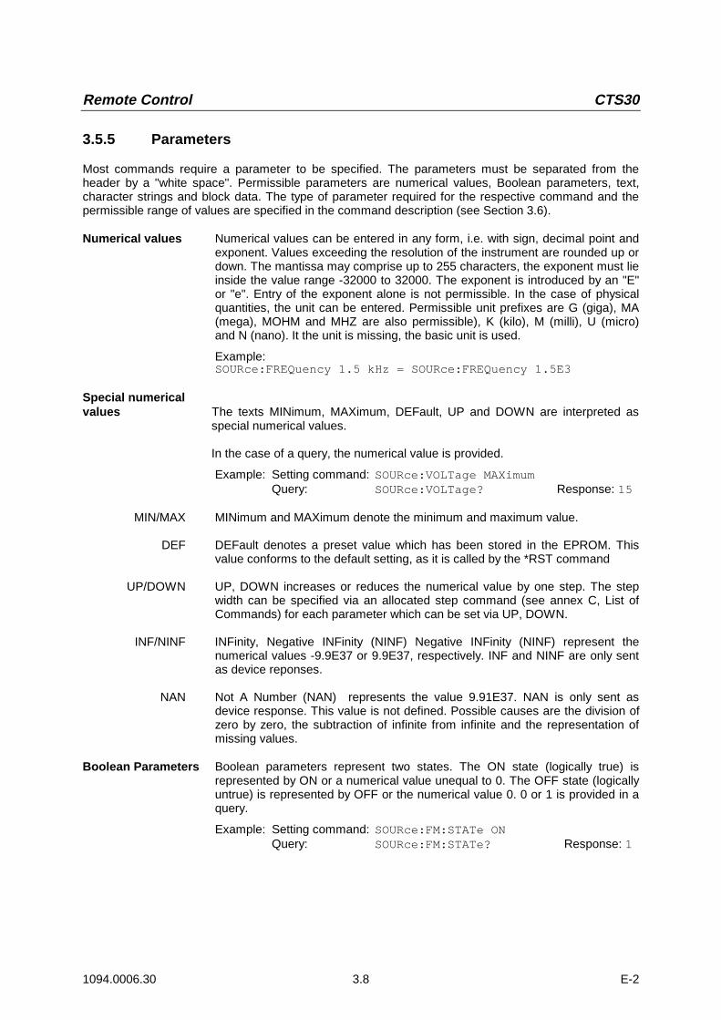
3.5.5 Parameters
Most commands require a parameter to be specified. The parameters must be separated from theheader by a "white space". Permissible parameters are numerical values, Boolean parameters, text,character strings and block data. The type of parameter required for the respective command and thepermissible range of values are specified in the command description (see Section 3.6).
Numerical values Numerical values can be entered in any form, i.e. with sign, decimal point andexponent. Values exceeding the resolution of the instrument are rounded up ordown. The mantissa may comprise up to 255 characters, the exponent must lieinside the value range -32000 to 32000. The exponent is introduced by an "E"or "e". Entry of the exponent alone is not permissible. In the case of physicalquantities, the unit can be entered. Permissible unit prefixes are G (giga), MA(mega), MOHM and MHZ are also permissible), K (kilo), M (milli), U (micro)and N (nano). It the unit is missing, the basic unit is used.
Example:SOURce:FREQuency 1.5 kHz = SOURce:FREQuency 1.5E3
Special numericalvalues The texts MINimum, MAXimum, DEFault, UP and DOWN are interpreted as
special numerical values.
In the case of a query, the numerical value is provided.
Example: Setting command: SOURce:VOLTage MAXimumQuery: SOURce:VOLTage? Response: 15
MIN/MAX MINimum and MAXimum denote the minimum and maximum value.
DEF DEFault denotes a preset value which has been stored in the EPROM. Thisvalue conforms to the default setting, as it is called by the *RST command
UP/DOWN UP, DOWN increases or reduces the numerical value by one step. The stepwidth can be specified via an allocated step command (see annex C, List ofCommands) for each parameter which can be set via UP, DOWN.
INF/NINF INFinity, Negative INFinity (NINF) Negative INFinity (NINF) represent thenumerical values -9.9E37 or 9.9E37, respectively. INF and NINF are only sentas device reponses.
NAN Not A Number (NAN) represents the value 9.91E37. NAN is only sent asdevice response. This value is not defined. Possible causes are the division ofzero by zero, the subtraction of infinite from infinite and the representation ofmissing values.
Boolean Parameters Boolean parameters represent two states. The ON state (logically true) isrepresented by ON or a numerical value unequal to 0. The OFF state (logicallyuntrue) is represented by OFF or the numerical value 0. 0 or 1 is provided in aquery.
Example: Setting command: SOURce:FM:STATe ONQuery: SOURce:FM:STATe? Response: 1
CTS30 Remote Control
1094.0006.30 3.9 E-2
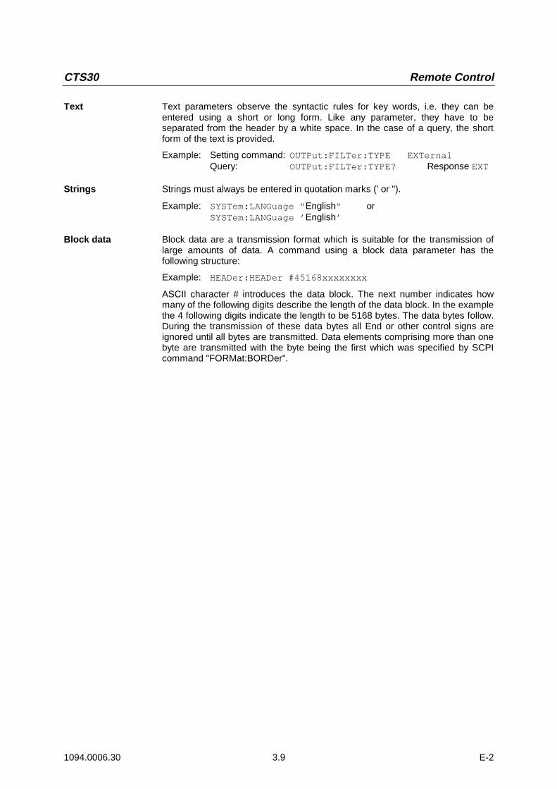
Text Text parameters observe the syntactic rules for key words, i.e. they can beentered using a short or long form. Like any parameter, they have to beseparated from the header by a white space. In the case of a query, the shortform of the text is provided.
Example: Setting command: OUTPut:FILTer:TYPE EXTernalQuery: OUTPut:FILTer:TYPE? Response EXT
Strings Strings must always be entered in quotation marks (’ or ").
Example: SYSTem:LANGuage "English" orSYSTem:LANGuage ’English’
Block data Block data are a transmission format which is suitable for the transmission oflarge amounts of data. A command using a block data parameter has thefollowing structure:
Example: HEADer:HEADer #45168xxxxxxxx
ASCII character # introduces the data block. The next number indicates howmany of the following digits describe the length of the data block. In the examplethe 4 following digits indicate the length to be 5168 bytes. The data bytes follow.During the transmission of these data bytes all End or other control signs areignored until all bytes are transmitted. Data elements comprising more than onebyte are transmitted with the byte being the first which was specified by SCPIcommand "FORMat:BORDer".

Remote Control CTS30
1094.0006.30 3.10 E-2
3.5.6 Overview of Syntax Elements
The following survey offers an overview of the syntax elements.
:
;
,
?
*
"
#
The colon separates the key words of a command.In a command line the colon after the separating semicolon marks the uppermost commandlevel.
The semicolon separates two commands of a command line. It does not alter the path.
The comma separates several parameters of a command.
The question mark forms a query.
The asterix marks a common command.
Quotation marks introduce a string and terminate it.
ASCII character # introduces block data.
A "white space (ASCII-Code 0 to 9, 11 to 32 decimal, e.g.blank) separates header and parameter.
CTS30 Remote Control
1094.0006.30 3.11 E-2
3.6 Description of Commands
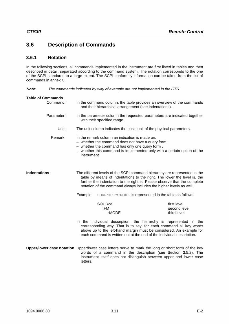
3.6.1 Notation
In the following sections, all commands implemented in the instrument are first listed in tables and thendescribed in detail, separated according to the command system. The notation corresponds to the oneof the SCPI standards to a large extent. The SCPI conformity information can be taken from the list ofcommands in annex C.
Note: The commands indicated by way of example are not implemented in the CTS.
Table of CommandsCommand: In the command column, the table provides an overview of the commands
and their hierarchical arrangement (see indentations).
Parameter: In the parameter column the requested parameters are indicated togetherwith their specified range.
Unit: The unit column indicates the basic unit of the physical parameters.
Remark: In the remark column an indication is made on:– whether the command does not have a query form,– whether the command has only one query form ,– whether this command is implemented only with a certain option of the
instrument.
Indentations The different levels of the SCPI command hierarchy are represented in thetable by means of indentations to the right. The lower the level is, thefarther the indentation to the right is. Please observe that the completenotation of the command always includes the higher levels as well.
Example: SOURce:FM:MODE iis represented in the table as follows:
SOURce first level:FM second level
:MODE third level
In the individual description, the hierarchy is represented in thecorresponding way. That is to say, for each command all key wordsabove up to the left-hand margin must be considered. An example foreach command is written out at the end of the individual description.
Upper/lower case notation Upper/lower case letters serve to mark the long or short form of the keywords of a command in the description (see Section 3.5.2). Theinstrument itself does not distinguish between upper and lower caseletters.

Remote Control CTS30
1094.0006.30 3.12 E-2
Special characters | A selection of key words with an identical effect exists for severalcommands. These key words are indicated in the same line, they areseparated by a vertical stroke. Only one of these key words has to beindicated in the header of the command. The effect of the command isindependent of which of the key words is indicated.
Example: SOURce:FREQuency
:CW|:FIXed
The two following commands of identical meaning can beformed. They set the frequency of the constantly frequent signalto 1 kHz:
SOURce:FREQuency:CW 1E3 = SOURce:FREQuency:FIXed 1E3
A vertical stroke in indicating the parameters marks alternative possibilitiesin the sense of "or". The effect of the command is different, depending onwhich parameter is entered.
Example: Selection of the parameters for the commandSOURce:COUPling AC | DC
If parameter AC is selected, only the AC content is fed through, inthe case of DC, the DC as well as the AC content.
[ ] Key words in square brackets can be omitted when composing the header(cf. Section 3.5.2, Optional Keywords). The full command length must beaccepted by the instrument for reasons of compatibility with the SCPIstandards.Parameters in square brackets can optionally be incorporated in thecommand or omitted as well.
{ } Parameters in braces can optionally be incorporated in the command eithernot at all, once or several times.

CTS30 Remote Control
1094.0006.30 3.13 E-2
3.6.2 Common Commands
The common commands are taken from the IEEE 488.2 (IEC 625-2) standard. Same commands havethe same effect on different devices. The headers of these commands consist of "*" followed by threeletters. Many common commands refer to the status reporting system which is described in detail inSection 3.8.
Table 3-1 Common Commands
Command Parameter Unit Remark
*CLS no query
*ESE 0...255
*ESR? only query
*IDN? only query
*IST? only query
*OPC
*OPT? only query
*PRE 0...255
*PSC 0 | 1
*RST no query
*SRE 0...255
*STB? only query
*TST? only query
*WAI
*CLSCLEAR STATUS sets the status byte (STB), the standard event register (ESR) and the EVENt-partof the QUEStionable and the OPERation register to zero. The command does not alter the mask andtransition parts of the registers. It clears the output buffer.
*ESE 0...255EVENT STATUS ENABLE sets the event status enable register to the value indicated. Query *ESE?returns the contents of the event status enable register in decimal form.
*ESR?STANDARD EVENT STATUS QUERY returns the contents of the event status register in decimalform (0 to 255) and subsequently sets the register to zero.

Remote Control CTS30
1094.0006.30 3.14 E-2
*IDN?IDENTIFICATION QUERY queries the instrument identification.The device response is for example:
ROHDE&SCHWARZ,CTSzz,ssssss/sss,x.xx yy.yy.yy(zz is the model no., eg 55 or 65ssssss/sss is the serial no., eg 101183/005x.xx is the software version, eg V 1.00yy.yy.yy is the date, eg 18.10.93)
*IST?INDIVIDUAL STATUS QUERY returns the contents of the IST flag in decimal form (0 | 1). The IST-flag is the status bit which is sent during a parallel poll.
*OPCOPERATION COMPLETE sets bit 0 in the event status register when all preceding commands havebeen executed. This bit can be used to initiate a service request (cf. Section 3.7).
*OPC?OPERATION COMPLETE QUERY writes message "1" into the output buffer as soon as allpreceding commands have been executed (cf. Section 3.7).
*OPT?OPTION IDENTIFICATION QUERY queries the options included in the instrument and returns a listof the options installed. The options are separated from each other by means of commas.
The responses have the following meaning:
B1 OCXO ReferenceB7 Module TestK6 Remote Control
Example of a device response: B1,,B7,,K6

CTS30 Remote Control
1094.0006.30 3.15 E-2
*PRE 0...255PARALLEL POLL REGISTER ENABLE sets parallel poll enable register to the value indicated.Query *PRE? returns the contents of the parallel poll enable register in decimal form.
*PSC 0 | 1POWER ON STATUS CLEAR determines whether the contents of the ENABle registers ismaintained or reset in switching on.
*PSC = 0 causes the contents of the status registers to be maintained. Thus a service requestcan be triggered in switching on in the case of a corresponding configuration of statusregisters ESE and SRE.
*PSC = 0 resets the registers.
Query *PSC? reads out the contents of the power-on-status-clear flag. The response can be 0 or 1.
*RSTRESET sets the instrument to a defined default status. The command essentially corresponds topressing the [RESET] key. The default setting is indicated in the description of commands.
*SRE 0...255SERVICE REQUEST ENABLE sets the service request enable register to the value indicated. Bit 6(MSS mask bit) remains 0. This command determines under which conditions a service request istriggered. Query *SRE? reads the contents of the service request enable register in decimal form. Bit6 is always 0.
*STB?READ STATUS BYTE QUERY reads the contents of the status byte in decimal form.
*TST?SELF TEST QUERY triggers selftests of the instrument and outputs an error code in decimal form.
WAIWAIT-to-CONTINUE only permits the servicing of the subsequent commands after all precedingcommands have been executed and all signals have settled (see also section 3.7 and "*OPC").

Remote Control CTS30
1094.0006.30 3.16 E-2
3.7 Instrument Model and Command Processing
The instrument model shown in Fig. 3-2 has been made viewed from the standpoint of the servicing ofremote-control commands. The individual components work independently of each other andsimultaneously. They communicate by means of so-called "messages".
RS232
Commandrecognition
Data set
Instrument hardware
RS232Output unit with
output buffer
Input unit with
input puffer
Status reporting-system
Fig. 3-2 Instrument model in the case of remote control

CTS30 Remote Control
1094.0006.30 3.17 E-2
3.8 Status Reporting System
The status reporting system (cf. Fig. 3-4) stores all information on the present operating state of theinstrument and on errors which have occurred. This information is stored in the status registers and inthe error queue. The status registers and the error queue can be queried via the remote-controlinterface.
The information is of a hierarchical structure. The register status byte (STB) defined in IEEE 488.2 andits associated mask register service request enable (SRE) form the uppermost level. The STB receivesits information from the standard event status register (ESR) which is also defined in IEEE 488.2 withthe associated mask register standard event status enable (ESE) and registers STATus:OPERation andSTATus:QUEStionable which are defined by SCPI and contain detailed information on the instrument.
The IST flag ("Individual STatus") and the parallel poll enable register (PPE) allocated to it are also partof the status reporting system. The IST flag, like the SRQ, combines the entire instrument status in asingle bit. The PPE fulfills an analog function for the IST flag as the SRE for the service request.
The output buffer contains the messages the instrument returns to the controller. It is not part of thestatus reporting system but determines the value of the MAV bit in the STB and thus is represented inFig. 3-4.
3.8.1 Structure of an SCPI Status Register
Each SCPI register consists of 5 parts which each have a width of 16 bits and have different functions(cf. Fig. 3-3). The individual bits are independent of each other, i.e. each hardware status is assigned abit number which is valid for all five parts. For example, bit 3 of the STATus:OPERation register isassigned to the hardware status "wait for trigger" in all five parts. Bit 15 (the most significant bit) is set tozero for all parts. Thus the contents of the register parts can be processed by the controller as positiveinteger.
15 14 13 12 PTRansition part 3 2 1 0
15 14 13 12 EVENT part 3 2 1 0
15 14 13 12 ENABle part 3 2 1 0
& & & & & & & & & & & & & & & &
to higher-order register
Sum bit & = logisch AND
= logisch ORof all bits
+
+
15 14 13 12 NTRansition part 3 2 1 0
15 14 13 12 CONDition part 3 2 1 0
Fig. 3-3 The status-register model

Remote Control CTS30
1094.0006.30 3.18 E-2
CONDition part The CONDition part is directly written into by the hardware or the sum bit ofthe next lower register. Its contents reflects the current instrument status. Thisregister part can only be read, but not written into or cleared. Its contents isnot affected by reading.
PTRansition part The Positive-TRansition part acts as an edge detector. When a bit of theCONDition part is changed from 0 to 1, the associated PTR bit decideswhether the EVENt bit is set to 1.PTR bit =1: the EVENt bit is set.PTR bit =0: the EVENt bit is not set.This part can be written into and read at will. Its contents is not affected byreading.
NTRansition part The Negative-TRansition part also acts as an edge detector. When a bit of theCONDition part is changed from 1 to 0, the associated NTR bit decideswhether the EVENt bit is set to 1.NTR-Bit = 1: the EVENt bit is set.NTR-Bit = 0: the EVENt bit is not set.This part can be written into and read at will. Its contents is not affected byreading.
With these two edge register parts the user can define which state transition ofthe condition part (none, 0 to 1, 1 to 0 or both) is stored in the EVENt part.
EVENt part The EVENt part indicates whether an event has occurred since the lastreading, it is the "memory" of the condition part. It only indicates eventspassed on by the edge filters. It is permanently updated by the instrument.This part can only be read by the user. During reading, its contents is set tozero. In linguistic usage this part is often equated with the entire register.
ENABle part The ENABle part determines whether the associated EVENt bit contributes tothe sum bit (cf. below). Each bit of the EVENt part is ANDed with theassociated ENABle bit (symbol ’&’). The results of all logical operations of thispart are passed on to the sum bit via an OR function (symbol ’+’).ENAB-Bit = 1: the associated EVENt bit does not contribute to the sum bitENAB-Bit = 0: if the associated EVENT bit is "1", the sum bit is set to "1" as
well.This part can be written into and read by the user at will. Its contents is notaffected by reading.
Sum bit As indicated above, the sum bit is obtained from the EVENt and ENABle partfor each register. The result is then entered into a bit of the CONDition part ofthe higher-order register.The instrument automatically generates the sum bit for each register. Thus anevent, e.g. a PLL that has not locked, can lead to a service request throughoutall levels of the hierarchy.
Note: The service request enable register SRE defined in IEEE 488.2 can be taken as ENABlepart of the STB if the STB is structured according to SCPI. By analogy, the ESE can betaken as the ENABle part of the ESR.

CTS30 Remote Control
1094.0006.30 3.19 E-2
3.8.2 Overview of the Status Registers
SRE STB
PPE
IST flag(Response to parallel poll)
& = logical AND
= logical OR of all bits
ESE ESR
Error queue Output buffer
SRQ
RQS/MSS
ESBMAV
Power onUser RequestCommand ErrorExecution ErrorDevice Dependent ErrorQuery Errorvacant
Operation Complete
-&--&--&--&--&--&-
-&-
-&--&--&--&-
-&--&--&--&--&--&--&--&-
76543210
0
1
234567
vacant
vacant
vacant
vacant
Fig. 3-4 Overview of status registers

Remote Control CTS30
1094.0006.30 3.20 E-2
3.8.3 Description of the Status Registers
3.8.3.1 Status Byte (STB) and Service Request Enable Register (SRE)
The STB is already defined in IEEE 488.2. It provides a rough overview of the instrument status bycollecting the pieces of information of the lower registers. It can thus be compared with the CONDitionpart of an SCPI register and assumes the highest level within the SCPI hierarchy. A special feature isthat bit 6 acts as the sum bit of the remaining bits of the status byte.The STATUS BYTE is read out using the command "*STB?".
Table 3-2 Meaning of the bits used in the satus byte
Bit No. Meaning
2 Error Queue not empty
The bit is set when an entry is made in the error queue.If this bit is enabled by the SRE, each entry of the error queue generates a Service Request. Thus an error canbe recognized and specified in greater detail by polling the error queue. The poll provides an informative errormessage. This procedure is to be recommended since it considerably reduces the problems involved withremote control.
4 MAV bit (message available)
The bit is set if a message is available in the output buffer which can be read.This bit can be used to enable data to be automatically read from the instrument to the controller.
5 ESB bit
Sum bit of the event status register. It is set if one of the bits in the event status register is set and enabled inthe event status enable register.Setting of this bit implies a serious error which can be specified in greater detail by polling the event statusregister.
6 MSS bit (master status smmary bit)
The bit is set if the instrument triggers a service request. This is the case if one of the other bits of this registersis set together with its mask bit in the service request enable register SRE.

CTS30 Remote Control
1094.0006.30 3.21 E-2
3.8.3.2 Event-Status-Reg. (ESR) and Event-Status-Enable-Reg. (ESE)
The ESR is already defined in IEEE 488.2. It can be compared with the EVENt part of an SCPI register.The event status register can be read out using command "*ESR?".The ESE is the associated ENABle part. It can be set using command "*ESE" and read using command"*ESE?".
Table 3-3 Meaning of the bits used in the event status register
Bit No. Meaning
0 Operation Complete
This bit is set on reception of the command *OPC exactly when all previous commands have been executed.
2 Query Error
This bit is set if either the controller wants to read data from the instrument without having sent a query, or if itdoes not fetch requested data and sends new instructions to the instrument instead. The cause is often a querywhich is faulty and hence cannot be executed.
3 Device-dependent Error
This bit is set if a device-dependent error occurs. An error message with a number between -300 and -399 or apositive error number, which denotes the error in greater detail, is entered into the error queue (cf. annex B,Error Messages).
4 Execution Error
This bit is set if a received command is syntactically correct, however, cannot be performed for other reasons.An error message with a number between -200 and -300, which denotes the error in greater detail, is enteredinto the error queue (cf. annex B, Error Messages).
5 Command Error
This bit is set if a command which is undefined or syntactically incorrect is received. An error message with anumber between -100 and -200, which denotes the error in greater detail, is entered into the rror queue (cf.annex B, -Error Messages).
6 User Request
This bit is set on pressing the LOCAL key, i. e., when the instrument is switched over to manual control.
7 Power On (supply voltage on)
This bit is set on switching on the instrument.

Remote Control CTS30
1094.0006.30 3.22 E-2
3.8.4 Error-Queue Query
Each error state in the instrument leads to an entry in the error queue. The entries of the error queueare detailed plain-text error messages which can be queried via the remote control using command"SYSTem:ERRor?". Each call of "SYSTem:ERRor?" provides an entry from the error queue. If no errormessages are stored there any more, the instrument responds with 0, "No error".
The error queue should be queried after every SRQ in the controller program as the entries describe thecause of an error more precisely than the status registers. Especially in the test phase of a controllerprogram the error queue should be queried regularly since faulty commands from the controller to theinstrument are recorded there as well.
3.8.5 Resetting Values of the Status Reporting System
Table 3-5 comprises the different commands and events causing the status reporting system to bereset. None of the commands, except for *RST and SYSTem:PRESet influences the functionalinstrument settings. In particular, DCL does not change the instrument settings.
Table 3-5 Resettting instrument functions
Event Switching on supplyvoltage
Power-On-Status-Clear
*RST orSYSTem:PRESet
STATus:PRESet *CLS
Effect 0 1
Clear STB,ESR yes yes
Clear ESE yes
Clear EVENTt parts of theregisters
yes yes
Clear error queue yes yes yes
Clear output buffer yes yes 1) 1) 1)
Clear commandprocessing and inputbuffer
yes yes yes
1) Every command being the first in a command line, i.e., immediately following a <PROGRAM MESSAGE TERMINATOR>clears the output buffer.

1079.2001.01 (Edition 3)
Test andMeasurement Division
Windows Application CTSgo
to
CTS-K6(Version 1.81)
1079.2001.01
Printed in the FederalRepublic of Germany


CTS-K6 Windows Application CTSgo
1079.2001.01 1 E-3
1 Contents
1 Contents ........................................................................................................................................... 1
2 Introduction..................................................................................................................................... 7
2.1 First Steps with CTSgo ............................................................................................................ 7
2.2 Basic Knowledge Required ..................................................................................................... 7
2.3 Preconditions for System Use ................................................................................................ 7
2.4 Suitable Serial Cables .............................................................................................................. 8
2.4.1 Cable for Xon/Xoff Protocol.............................................................................................. 8
2.4.2 Cable for Hardware Protocol RTS/CTS ........................................................................... 8
2.5 Equipment Supplied for CTS-K6 ............................................................................................. 8
3 Installation ....................................................................................................................................... 9
3.1 Preparation................................................................................................................................ 9
3.2 Procedure .................................................................................................................................. 9
3.2.1 Step 1 ............................................................................................................................... 9
3.2.2 Step 2 ............................................................................................................................... 9
3.2.3 Step 3 ............................................................................................................................... 9
3.2.4 Step 4 ............................................................................................................................... 9
3.2.5 Step 5 ............................................................................................................................. 10
3.2.6 Step 6 ............................................................................................................................. 10
3.2.7 Step 7 ............................................................................................................................. 11
3.2.8 Step 8 ............................................................................................................................. 11
3.2.9 Step 9 ............................................................................................................................. 12
3.2.10Step 10 ........................................................................................................................... 12
3.2.11Step 11 ........................................................................................................................... 13
4 Software Components.............................................................................................................. 14
4.1 Installation Components........................................................................................................ 14
4.2 Other Components ................................................................................................................. 14
5 Deinstallation of Program CTSgo........................................................................................ 15
5.1 Deinstallation under Windows 95/Windows 98 / Windows NT 4.0 .................................... 15
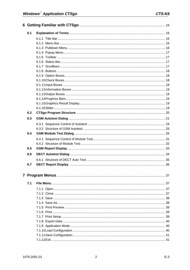
Windows Application CTSgo CTS-K6
1079.2001.01 2 E-3
6 Getting Familiar with CTSgo.................................................................................................. 16
6.1 Explanation of Terms ............................................................................................................. 16
6.1.1 Title Bar .......................................................................................................................... 16
6.1.2 Menu Bar........................................................................................................................ 16
6.1.3 Pulldown Menu............................................................................................................... 16
6.1.4 Popup Menu ................................................................................................................... 17
6.1.5 Toolbar ........................................................................................................................... 17
6.1.6 Status Bar....................................................................................................................... 17
6.1.7 Scrollbars ....................................................................................................................... 17
6.1.8 Buttons ........................................................................................................................... 18
6.1.9 Option Boxes.................................................................................................................. 18
6.1.10Check Boxes .................................................................................................................. 18
6.1.11Input Boxes .................................................................................................................... 18
6.1.12Information Boxes .......................................................................................................... 19
6.1.13Output Boxes.................................................................................................................. 19
6.1.14Progress Bars................................................................................................................. 19
6.1.15Graphics Result Display ................................................................................................. 19
6.1.16Slider .............................................................................................................................. 19
6.2 CTSgo Program Structure ..................................................................................................... 20
6.3 GSM Autotest Dialog .............................................................................................................. 21
6.3.1 Sequence Control of Autotest ........................................................................................ 24
6.3.2 Structure of GSM Autotest ............................................................................................. 25
6.4 GSM Module Test Dialog ....................................................................................................... 26
6.4.1 Sequence Control of Module Test.................................................................................. 31
6.4.2 Structure of Module Test ................................................................................................ 32
6.5 GSM Report Display ............................................................................................................... 33
6.6 DECT Autotest Dialog ............................................................................................................ 34
6.6.1 Structure of DECT Auto Test ......................................................................................... 35
6.7 DECT Report Display ............................................................................................................. 36
7 Program Menus ........................................................................................................................... 37
7.1 File Menu ................................................................................................................................. 37
7.1.1 Open............................................................................................................................... 37
7.1.2 Close .............................................................................................................................. 37
7.1.3 Save ............................................................................................................................... 38
7.1.4 Save As .......................................................................................................................... 38
7.1.5 Print Preview .................................................................................................................. 39
7.1.6 Print ................................................................................................................................ 39
7.1.7 Print Setup...................................................................................................................... 39
7.1.8 Export Data .................................................................................................................... 40
7.1.9 Application Mode............................................................................................................ 40
7.1.10Load Configuration ......................................................................................................... 40
7.1.11Save Configuration......................................................................................................... 41
7.1.12Exit ................................................................................................................................. 41

CTS-K6 Windows Application CTSgo
1079.2001.01 3 E-3
7.2 Measurement Menus .............................................................................................................. 42
7.2.1 Report Settings............................................................................................................... 42
7.2.2 Start ................................................................................................................................ 44
7.2.3 Stop ................................................................................................................................ 44
7.2.4 Pause ............................................................................................................................. 44
7.2.5 Step ................................................................................................................................ 44
7.2.6 Freeze ............................................................................................................................ 44
7.2.7 Continue ......................................................................................................................... 44
7.3 Configuration Menu in the GSM Autotest ............................................................................ 45
7.3.1 Network .......................................................................................................................... 46
7.3.2 Test Parameters............................................................................................................. 47
7.3.3 Select Tests.................................................................................................................... 48
7.3.4 First Connect .................................................................................................................. 49
7.3.5 Test Set 1 ....................................................................................................................... 49
7.3.6 Test Set 2 ....................................................................................................................... 51
7.3.7 Test Set 3 ....................................................................................................................... 51
7.3.8 Test Set 4 ....................................................................................................................... 51
7.3.9 Test Set 5 ....................................................................................................................... 51
7.3.10Test Set 6 ....................................................................................................................... 51
7.3.11First Disconnect.............................................................................................................. 52
7.3.12Second Connect............................................................................................................. 52
7.3.13Test Set 7 ....................................................................................................................... 52
7.3.14Test Set 8 ....................................................................................................................... 52
7.3.15Test Set 9 ....................................................................................................................... 53
7.3.16Test Set 10 ..................................................................................................................... 53
7.3.17Test Set 11 ..................................................................................................................... 53
7.3.18Test Set 12 ..................................................................................................................... 53
7.3.19Second Disconnect ........................................................................................................ 53
7.3.20Remote Port ................................................................................................................... 54
7.3.21Change Password .......................................................................................................... 55
7.4 Configuration Menu in the GSM Module Test ..................................................................... 56
7.4.1 Attenuation ..................................................................................................................... 56
7.4.2 Generator Settings ......................................................................................................... 56
7.4.3 Burst Analysis Settings................................................................................................... 59
7.4.4 IQ Spectrum Settings ..................................................................................................... 62
7.4.5 Remote Port ................................................................................................................... 64
7.4.6 Change Password .......................................................................................................... 64

Windows Application CTSgo CTS-K6
1079.2001.01 4 E-3
7.5 Configuration Menu in the DECT Autotest .......................................................................... 65
7.5.1 PP Base Settings ........................................................................................................... 65
7.5.2 FP Base Settings............................................................................................................ 66
7.5.3 Select Tests.................................................................................................................... 68
7.5.4 FP Test Set 1 ................................................................................................................. 69
7.5.5 FP Test Set 2 ................................................................................................................. 70
7.5.6 FP Test Set 3 ................................................................................................................. 70
7.5.7 FP Test Set 4 ................................................................................................................. 70
7.5.8 FP Test Set 5 ................................................................................................................. 71
7.5.9 FP Test Set 6 ................................................................................................................. 71
7.5.10PP Test Set 1 ................................................................................................................. 72
7.5.11PP Test Set 2 ................................................................................................................. 73
7.5.12PP Test Set 3 ................................................................................................................. 73
7.5.13PP Test Set 4 ................................................................................................................. 73
7.5.14PP Test Set 5 ................................................................................................................. 73
7.5.15PP Test Set 6 ................................................................................................................. 74
7.5.16Remote Port ................................................................................................................... 74
7.5.17Change Password .......................................................................................................... 74
7.6 Limits Menu in the GSM Autotest ......................................................................................... 75
7.6.1 Phase / Frequency / Timing ........................................................................................... 75
7.6.2 Average Power ............................................................................................................... 76
7.6.3 BER Measurements ....................................................................................................... 78
7.6.4 RXQual /RXLev .............................................................................................................. 79
7.7 Limits Menu in the DECT Autotest ....................................................................................... 81
7.7.1 NTP Measurements ....................................................................................................... 81
7.7.2 Modulation...................................................................................................................... 82
7.7.3 Timing............................................................................................................................. 83
7.7.4 BER / FER...................................................................................................................... 84
7.8 Window Menu ......................................................................................................................... 85
7.8.1 Zoom 200%.................................................................................................................... 85
7.8.2 Zoom 150%.................................................................................................................... 85
7.8.3 Zoom 133%.................................................................................................................... 85
7.8.4 Normal............................................................................................................................ 85
7.8.5 Zoom 75%...................................................................................................................... 86
7.8.6 Zoom 66%...................................................................................................................... 86
7.8.7 Zoom 50%...................................................................................................................... 86
7.8.8 Zoom in .......................................................................................................................... 86
7.8.9 Zoom out ........................................................................................................................ 86
7.9 Help Menu ............................................................................................................................... 86
7.9.1 Contents ......................................................................................................................... 86
7.9.2 Using the Online Help .................................................................................................... 88
7.9.3 Info About ....................................................................................................................... 88

CTS-K6 Windows Application CTSgo
1079.2001.01 5 E-3
8 GSM Measurement Report...................................................................................................... 89
8.1 Header of Measurement Report ............................................................................................ 89
8.2 Output of Measurement Information in the Report ............................................................. 90
8.3 Summary of Results in the Measurement Report ............................................................... 91
8.4 Appendix to Measurement Report ........................................................................................ 91
9 DECT Measurement Report.................................................................................................... 95
9.1 Header of Measurement Report ............................................................................................ 95
9.2 Output of Measurement Information in the Report ............................................................. 95
9.3 Summary of Measurements in the Measurement Report ................................................... 96
9.4 Appendix to Measurement Report ........................................................................................ 96
10Drag & Drop Support................................................................................................................. 99
11Exchanging Measurement Report Data .......................................................................... 100
12Examples of Application........................................................................................................ 101
12.1 Simple GSM Echo Test ........................................................................................................ 101
12.2 Extended GSM Test.............................................................................................................. 102
12.3 DECT Test ............................................................................................................................. 103
13Working with Different User Profiles ............................................................................... 104
13.1 The Configurator Profile ...................................................................................................... 104
13.2 The Operator Profile............................................................................................................. 104
14Integrating Operator-specific Hints .................................................................................. 105
14.1 The Section Everytime ......................................................................................................... 106
14.2 The Section Daily.................................................................................................................. 106
14.3 The Section Monthly ............................................................................................................ 107
14.4 The Section Topic................................................................................................................. 107
14.5 The Section TestsPassed .................................................................................................... 107
14.6 The Section TestsFailed ...................................................................................................... 107
15Adapting the Appearance of CTSgo ................................................................................. 108

Windows Application CTSgo CTS-K6
1079.2001.01 6 E-3
16Problems, Questions and Solutions ................................................................................ 109
16.1 Components Missing Signaled upon Program Startup.................................................... 109
16.2 Serial Interface Cannot be Opened..................................................................................... 109
16.3 CTS Cannot be Remote-Controlled .................................................................................... 109
16.4 Program Signals Timeout .................................................................................................... 109
16.5 Serial Data Transmission Impaired by Mouse Movements .............................................. 109
16.6 Location Update Cannot be Performed.............................................................................. 110
16.7 Synchronization Lost ........................................................................................................... 110
16.8 Level Measurements Frequently out of Tolerance............................................................ 110
16.9 Measurement Report Cannot be Loaded ........................................................................... 110
16.10 Drag & Drop not Working .................................................................................................... 110
16.11 Program Cannot be Configured .......................................................................................... 110
16.12 Generator Settings are not Immediately Performed ......................................................... 110
16.13 Can Several CTSs be Controlled from a PC ? ................................................................... 111
16.14 Can CTSgo be Performed in the Background? ................................................................. 111
16.15 Can Configuration Files be Read or Printed?.................................................................... 111
16.16 Can Configuration Overwriting be Avoided? .................................................................... 113
16.17 Can Default Values be Loaded?.......................................................................................... 113
17Other Features ........................................................................................................................... 114
17.1 Debugging ............................................................................................................................. 114
17.2 Demo Feature........................................................................................................................ 114
17.3 Generate Code Feature ........................................................................................................ 114
18Index............................................................................................................................................... 115

CTS-K6 Windows Application CTSgo
1079.2001.01 7 E-3
2 Introduction
We are very pleased to be able to present CTSgo for Windows to you. This program offerscomprehensive capabilities for the remote control of Digital Radio Testers CTS50, CTS55 or CTS65. Itoffers in addition an autotest with versatile configurations for GSM and DECT and an interactivemodule test for GSM mobile phones. Autotest results are documented in an informative report, whichcan be stored and printed.
All brand names and product names in this manual are registered trademarks of the respectivemanufacturer or enterprise.
2.1 First Steps with CTSgo
The best way to get familiar with a program is learning by doing, ie to utilize the functions and practicetheir application. New users of CTSgo are advised to read carefully through the manual or to use theonline help provided by the program. A section of this manual also gives practical hints and exampleson the use of CTSgo.
2.2 Basic Knowledge Required
Before using CTSgo, you should be familiar with the basic operation of Microsoft Windows. Thismeans that you should be able to open and close a Windows application program and know how touse the mouse. For more detailed information on Windows refer to the Microsoft Windows usermanual.
2.3 Preconditions for System Use
The CTSgo program comes in a version for use under Windows 95, Windows 98 or Windows NT 4.0.
The program may be installed in German or English as desired. More information is given in theProgram Installation Section.To ensure unimpaired functioning of CTSgo, your system should meet the following basicrequirements. For a more convenient use of CTSgo, particularly the presentation of measurementreports, the employed graphics card should have a better resolution than the one specified below.
CTS30, CTS50, CTS55 or CTS65 is also required. To be able to make full use of all the programcapabilities, software version 2.00 or higher should be installed on the CTS. The autotest can beperformed as of software version 1.25 of the CTS. A test SIM card (eg Rohde & Schwarz CRT-Z2,Order Number 1039.9005.02) is also required.
A serial cable should be used for connecting your PC to the CTS. Suitable cables are described in thefollowing section.
Platform: Windows 95 / Windows 98 / Windows NT 4.0Processor: Pentium 166RAM: 16 MByteDisplay: VGA 640x480 pixelsHard-disk storage: 5 MBytePeripherals: Mouse, one free serial interface

Windows Application CTSgo CTS-K6
1079.2001.01 8 E-3
2.4 Suitable Serial Cables
The CTSgo program and the CTS allow for various settings of data transmission. Depending on thehandshake method used, different conditions have to be met by the cable. Handshake means that thedevices inform each other whether they are ready to receive data. Disabling the handshake function bysetting NONE is not recommended. In the description it is assumed that a 9-contact connector is fittedat both cable ends.
2.4.1 Cable for Xon/Xoff Protocol
2.4.2 Cable for Hardware Protocol RTS/CTS
2.5 Equipment Supplied for CTS-K6
The GSM Remote Control Option CTS-K6 (Rohde & Schwarz Order No. 1079.2001.01) comprises thefollowing software components as well as a document with the CTS unblocking code.
• Data record “CTSgo for Windows 95 / 98 /NT 4.0 “ German version• Data record “CTSgo for Windows 95 / 98 /NT 4.0 “ English version
Pin Designation1 DCD (Data Carrier Detect)2 RxD (Receive Data)3 TxD (Transmit Data)4 DTR (Data Terminal Ready)5 GND (Ground)6 DSR (Data Set Ready)7 RTS (Request To Send)8 CTS (Clear To Send)9 RI (Ring Indicator)
Fig.: Pin assignment ofRS-232-C interface
Cable end A Cable end BPin 2 (RxD) Pin 3 (TxD)Pin 3 (TxD) Pin 2 (RxD)Pin 5 (GND) Pin 5 (GND)
Cable end A Cable end BPin 2 (RxD) Pin 3 (TxD)Pin 3 (TxD) Pin 2 (RxD)Pin 7 (RTS) Pin 8 (CTS)Pin 8 (CTS) Pin 7 (RTS)Pin 5 (GND) Pin 5 (GND)

CTS-K6 Windows Application CTSgo
1079.2001.01 9 E-3
3 Installation
This section describes the installation of CTSgo. The appearance of Windows is slightly different onyour PC because of the various possible configurations, but the program contents and function ofcontrol elements are identical.
3.1 Preparation
Take the set of floppies for the CTSgo variant to be installed.
3.2 Procedure
3.2.1 Step 1
Insert the first floppy into the disk drive.
3.2.2 Step 2
Select the disk drive where the floppy is inserted. With Windows 95 / 98 / NT4.0, click on the MyComputer icon on the Windows desktop.
3.2.3 Step 3
Click on “Setup“ to call the execution file.
3.2.4 Step 4
The program will guide youstep by step through theinstallation. The followingwelcome screen is displayedon your PC.
Press “Next” to call the nextstep.
Fig.: Dialog of installation step 4

Windows Application CTSgo CTS-K6
1079.2001.01 10 E-3
3.2.5 Step 5
Enter your name and thename of your company in thedialog fields. After the entrycontinue with “Next”. Returnto the last step is possible atany time by pressing “Back”.
3.2.6 Step 6
The installation software nowasks for the target directorywhere the CTSgo software isto be installed. Press“Browse” if you do not wish touse the proposed directory.The software can be copiedinto any directory. The nextstep is again called with the“Next” button.
Fig.: Dialog of installation step 5
Fig.: Dialog of installation step 6

CTS-K6 Windows Application CTSgo
1079.2001.01 11 E-3
3.2.7 Step 7
Select the folder into whichthe program icon is to beplaced. You may create a newfolder or put the icon into analready existing folder.
3.2.8 Step 8
The installation software nowdisplays all the settings madebefore it starts to copy thesoftware components. Press“Back” if you wish to makefurther changes, otherwisepress “Next”.
Fig.: Dialog of installation step 7
Fig.: Dialog of installation step 8

Windows Application CTSgo CTS-K6
1079.2001.01 12 E-3
3.2.9 Step 9
The installation software nowstarts to copy the softwarecomponents. If desired, theinstallation procedure can beterminated before completionwith “Cancel”. A progress barinforms you on the currentinstallation state.
3.2.10 Step 10
During the installation theprogram may prompt you toinsert the next floppy. In thiscase remove the first floppyfrom the disk and insert thenext one as requested.
Fig.: Dialog of installation step 9
Fig.: Dialog of installation step 10

CTS-K6 Windows Application CTSgo
1079.2001.01 13 E-3
3.2.11 Step 11
The installation was success-fully completed. With theinstallation terminated, theprogram can be called up.
Fig.: Dialog of installation step 11

Windows Application CTSgo CTS-K6
1079.2001.01 14 E-3
4 Software Components
The installation program installs the following components. To simplify deinstallation of the program,the components should preferably not be copied into the Windows directory. If further applications areto be used and copied to the Windows system directory by the runtime libraries below, these librariesmay be cleared from the installation directory. This should only be done if problems occur with theremaining hard disk memory.
4.1 Installation Components
4.2 Other Components
During your work with the CTSgo software, configurations can be stored and called again. This allowstest limits and the extent of tests to be specified for the different types of mobile phones. Test resultscan also be stored.
Directory (example) Component FunctionC:\CTSGO\ CTS_GO.EXE ProgramC:\CTSGO\ CTS_GO.HLP Online helpC:\CTSGO\ CTS_GO.INI Initialization fileC:\CTSGO\ CTS_GO.ULV Definition of user levelC:\CTSGO\ BDS52F.DLL 32-bit runtime libraryC:\CTSGO\ CW3230.DLL 32-bit runtime libraryC:\CTSGO\ OWL52F.DLL 32-bit runtime libraryC:\CTSGO\ _DEISREG32.ISR Deinstallation fileC:\CTSGO\ _ISREG32.DLL Deinstallation fileC:\CTSGO\ DELSL1.ISU Deinstallation fileC:\CTSGO\AUTOSAVE SAMPLE.MRP Example of measurement report
Directory Component Functionany *.MRP Measurement reportsany *.CFG Saved configurationsC:\CTSGO\ CTS_GO.DS1 User-defined hints under GSMC:\CTSGO\ CTS_GO.DS2 User-defined hints under DECT

CTS-K6 Windows Application CTSgo
1079.2001.01 15 E-3
5 Deinstallation of Program CTSgo
Deinstallation is basically automatic on all platforms. The automatic deinstallation clears all files thathave been stored in the controller during the installation. Other files like configuration files ormeasurement reports are not cleared. If required, these files must be manually removed.
5.1 Deinstallation under Windows 95/Windows 98 / Windows NT 4.0
To deinstall CTSgo go to the Windows system control level and click on “Software”. A list of thesoftware will be displayed that can be automatically cleared. The list contains the entry “CTSgo forWindows“. Select this entry and then press the “Add/Remove” button.

Windows Application CTSgo CTS-K6
1079.2001.01 16 E-3
6 Getting Familiar with CTSgo
6.1 Explanation of Terms
If you are familiar with other Windows programs, associated terms and concepts will be known to you.However, to simplify your working with this manual and for the sake of clarity we recommend to brieflyread through the terms used in the manual.
6.1.1 Title Bar
This is the horizontal bar at the top of the display. In this bar the title of the window is displayed. After aclick on the bar and drawing the mouse, the CTSgo window can be shifted on the screen. By clickingthe icons at the left and right end of the title bar, the CTSgo window can be reduced to an icon in thetask bar, displayed at full size or closed.
6.1.2 Menu Bar
This is the line below the title bar, where the menu names are displayed. A click on a menu nameopens a pulldown menu with a list of commands for the selection of CTSgo functions.
6.1.3 Pulldown Menu
This is a command line which is pulled down after clicking on a menu name in the menu bar. Move themouse cursor through the list and select the desired command by a click on the left mouse key. Apulldown menu may contain further menus, the so-called submenus. You can recognize thesesubmenus by the arrows that point to the left or right. If you move the mouse to such a menu item thesubmenu will be opened.
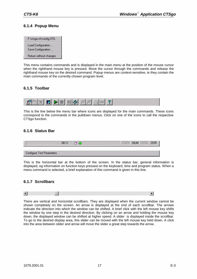
CTS-K6 Windows Application CTSgo
1079.2001.01 17 E-3
6.1.4 Popup Menu
This menu contains commands and is displayed in the main menu at the position of the mouse cursorwhen the righthand mouse key is pressed. Move the cursor through the commands and release therighthand mouse key on the desired command. Popup menus are context-sensitive, ie they contain themain commands of the currently chosen program level.
6.1.5 Toolbar
This is the line below the menu bar where icons are displayed for the main commands. These iconscorrespond to the commands in the pulldown menus. Click on one of the icons to call the respectiveCTSgo function.
6.1.6 Status Bar
This is the horizontal bar at the bottom of the screen. In the status bar, general information isdisplayed, eg information on function keys pressed on the keyboard, time and program status. When amenu command is selected, a brief explanation of this command is given in this line.
6.1.7 Scrollbars
There are vertical and horizontal scrollbars. They are displayed when the current window cannot beshown completely on the screen. An arrow is displayed at the end of each scrollbar. The arrowsindicate the direction into which the window can be shifted. A brief click with the left mouse key shiftsthe window by one step in the desired direction. By clicking on an arrow and holding the mouse keydown, the displayed window can be shifted at higher speed. A slider is displayed inside the scrollbar.To go to the desired display area, this slider can be moved with the left mouse key held down. A clickinto the area between slider and arrow will move the slider a great step towards the arrow.

Windows Application CTSgo CTS-K6
1079.2001.01 18 E-3
6.1.8 Buttons
Buttons are part of dialog windows. Click on a button with the left mouse key to execute the desiredfunction.
6.1.9 Option Boxes
Option boxes permit to select one of several different options. The selected option is filled in by a point.
6.1.10 Check Boxes
With these boxes an option can be activated or deactivated. The option is activated when an X or hookis displayed in the box. It is deactivated when the box is empty.
6.1.11 Input Boxes
Text or numerals can be entered in these fields. If it is necessary to check the range of the input value,press the OK button in the dialog. In this case you are prompted to repeat the entry with permissiblevalues.
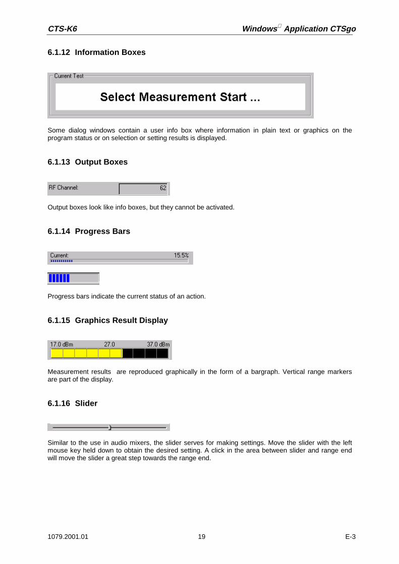
CTS-K6 Windows Application CTSgo
1079.2001.01 19 E-3
6.1.12 Information Boxes
Some dialog windows contain a user info box where information in plain text or graphics on theprogram status or on selection or setting results is displayed.
6.1.13 Output Boxes
Output boxes look like info boxes, but they cannot be activated.
6.1.14 Progress Bars
Progress bars indicate the current status of an action.
6.1.15 Graphics Result Display
Measurement results are reproduced graphically in the form of a bargraph. Vertical range markersare part of the display.
6.1.16 Slider
Similar to the use in audio mixers, the slider serves for making settings. Move the slider with the leftmouse key held down to obtain the desired setting. A click in the area between slider and range endwill move the slider a great step towards the range end.

Windows Application CTSgo CTS-K6
1079.2001.01 20 E-3
6.2 CTSgo Program Structure
CTSgo uses five main operating modes:
• GSM autotest dialog. The GSM autotest can be started in this mode for generating newmeasurement reports.
• GSM module test dialog. This is an interactive mode where generator settings can be made on theCTS, a GSM burst analysis performed and the IQ spectrum viewed.
• GSM report display. In this mode, recorded GSM measurement reports can be loaded, viewed,saved or printed.
• DECT autotest dialog. In this mode, the DECT autotest can be started for generating newmeasurement reports.
• DECT report display. In this mode, recorded DECT measurement reports can be loaded, viewed,saved or printed.

CTS-K6 Windows Application CTSgo
1079.2001.01 21 E-3
6.3 GSM Autotest Dialog
After the first start, the CTSgo program is in the GSM autotest mode. The sequence control of theautotest is in the stop mode at this point in time. If you wish to change settings for the autotest, youshould do it now. The individual menus and associated commands are described in the followingsections.
The autotest dialog comprises four main windows:
• “Message” window where the progress of the tests is indicated. If required, user prompts can alsobe displayed. So, for instance, the instruction to switch the mobile off and on again to initiate alocation update.
• “Current Test” window where the currently performed autotest step is described.• Progress bars informing on the state of the current test and of the total test to allow the user to
estimate the remaining test time.• Result window for indicating the number of performed tests with a distinction made between tests
passed and tests failed.
The dialog also comprises a button for terminating the program.In the status bar, the time and information on keyboard settings are displayed.
Fig.: CTSgo in GSM autotest mode

Windows Application CTSgo CTS-K6
1079.2001.01 22 E-3
The following elements are displayed to the right of the time of the day:
Status indication of program sequence. The status check in the sequence control is madeperiodically. With each performed cycle the icon is rotated by 90°. Events on the serial interface
also cause the icon to move. If the icon does not rotate, the Windows system is overloaded. In thiscase terminate all other programs, if required, also terminate and restart CTSgo.
Status information on CTS operating status. In some sequences of the autotest, the sequencecontrol queries the CTS operating status. Each icon corresponds to a specific status of CTS. The
device states shown below are described in the remote-control section of the CTS manual. The redlamp indicates an undefined device status.
IDLE (switch-on status of CTS).
MIDL (BCCH being generated).
MSYN (Location Update terminated).
MCE (call set up).
A progress bar to the right of the CTS status icon informs the user onthe status of the serial interface. At each write and read event the baris started from the left side. The end position of the bar at the right isreached when a timeout of the remote-control interface occurs. Thismaximum waiting time for an interface response can be configured bythe user.Pressing the righthand mouse key in the autotest dialog window opensa popup menu , where previously entered parameter sets can bestored as configuration files for reloading later on. The paths of up toeight stored configuration files are displayed. Move to the desired entrywith the righthand mouse key held down and then release the key.The selected file is loaded and the name of the selected configurationfile is displayed in the title bar.
The interaction of the mobile phone and autotest is indicated in the Message field. The followinganimated icons are used:
The test expects the mobile to synchronize to the base station signal of the CTS.
The mobile rings and waits for call pick-up. This status is shown by a to and fro movementof the displayed handy.
The transmitter and receiver tests are in progress.
You are requested to terminate the call. The left key on the mobile shown in red flashesduring animation.
Fig.: Popup menu in GSMautotest dialog

CTS-K6 Windows Application CTSgo
1079.2001.01 23 E-3
You are requested to set up a call. The righthand key on the mobile shown in greenflashes.

Windows Application CTSgo CTS-K6
1079.2001.01 24 E-3
6.3.1 Sequence Control of Autotest
With the CTSgo program, the autotest mode is called. The sequence control is in the stop mode sothat you can perform the configurations that are still needed. In this mode, you may choose betweenthe following possibilities:
Observe the appearance of the described block in the toolbar during autotest control.
Note:Commands of the menu bar can only be called in stop mode. After the change to the stop mode, thesequence control is reset. Restarting the sequence control restarts the autotest.
The single-step com-mand changes theappearance of the con-trol block. The sequencecontrol stops when thesingle step is terminated.
The program is in thestop mode. The autotestis started when the startcommand is executed.
The program is in the testmode. When the waitcommand is called, theprogram stops after thenext single step.
The program is in thewait mode. You have thechoice to continue withthe next step or tochange to the test modewith the single-stepcommand or the waitcommand.
The program is in the testmode. In this mode, thetests can be stopped withthe stop command. Thesequence controlassumes its initial state.
The control block doesnot change before thesingle step is terminated.

CTS-K6 Windows Application CTSgo
1079.2001.01 25 E-3
6.3.2 Structure of GSM Autotest
Call clear-down
Further call
setup?
Test evaluation
yes
no
Change of channel/PCL
Power/phase/frequency error measurements
Power reduction to BER level
Determination of BER, query of RXLev / RXQual
Preparation of test (further test runs)
Setting CTS output level
CTS basic configuration
Preparation of test (1st run)
Waiting for location update
Query of mobile specification (IMSI/IMEI/power class/phase)
Call setup
Furthertest set
requested?
no yes
OtherPCL requested
in the test set?
yes
no

Windows Application CTSgo CTS-K6
1079.2001.01 26 E-3
6.4 GSM Module Test Dialog
The GSM module test comprises three functions: operation of the CTS as generator, burst analysisusing the CTS and IQ spectrum display. The module test and thus data transmission between CTSand CTSgo start in generator mode. The left block in the dialog window indicates which of the tengenerator sets has been activated. A generator set includes the channel, the associated frequencyoffset, and the output level of the generator. The set level applies to connector RF In/Out or RF Out 2of the CTS, depending on the setting. This setting can be seen under the option Used RF connector.The boxes of the block indicate whether the generator is switched on, whether the output signalcontains a bit modulation or whether a ramped or continuous signal is used. The midamble used isindicated in another box of the window. To simplify the use of dual-band or triple-band mobiles, thenetwork definition and the RF attenuation value between mobile and measuring instrument CTS arealso part of the generator set. The network and the attenuation value of the current generator set canbe seen in the right block.
Important:With bit modulation switched off, the displayed training sequence is of no importance. All other settingsare ineffective when the generator is switched off.
One of the ten generator sets can be selected using the buttons Generator 01 to „Generator 10“. TheCTSgo program will act differently depending on whether the Set only box is activated or not. With thisbox activated, new generator settings are immediately active. When the box is empty, the user isrequested in a dialog to enter the desired generator settings. Terminating the dialog with OK sets theentries.
Fig.: CTSgo in GSM module test mode

CTS-K6 Windows Application CTSgo
1079.2001.01 27 E-3
The RF generator dialog can also be terminated with Cancel. In this case, the generator settings arenot changed. If required, the channel and the frequency offset can be converted to a frequency withthe aid of this dialog. For further information refer to the dialog description.
Like in the autotest, the user can load parameters or store the currentsetting with the aid of a popup menu. In this case, the generatorsettings are overwritten. This enables the user to define more than tengenerator sets by including configurations in the definitions of therequired generator sets. This popup menu can only be activated with aclick on the righthand mouse key when the sequence control is in thestop mode. Loading of configuration files also changes the autotestsettings as well as the burst analysis parameters and the IQ spectrum.The burst analysis mode can be selected by pressing one of thebuttons Overview, Power ramp or Phase error. Depending on the keyselected, a different popup window for the result display will appear.The appearance in the left frame of the module test dialog window isalso changed. The parameter set of the burst analysis is nowdisplayed. It comprises the selected channel, the expected power atthe input of the CTS, the trigger mode and the training sequence ofthe signal to be measured. The keypad now contains the ten buttonsAnalyzer 01 to Analyzer 10 for activating one of the ten parameter sets
for burst analysis. As with generator mode, the network selected GSM900, GSM1800 or GSM1900 andthe attenuation are part of the parameter set, the associated values are indicated at the right of themodule test dialog.
The results of the burstanalysis are displayed inthe popup window BurstAnalysis Overview“ .The desiredmeasurement can beactivated by means ofthe boxes. Theassociated numericalresult is displayed in therespective field. Themeasurement result isalso displayed asbargraph in the graphicsresult display . Themeasurement range canbe varied using theslider below thebargraph . Moving theslider to the left reducesthe measurementrange, moving it to theright extends the range.The bargraphs for thedifferent measurementswith range limits areshown below:
Fig.: Popup menu in GSMmodule test dialog
Fig.: Popup menu in GSM module test dialog
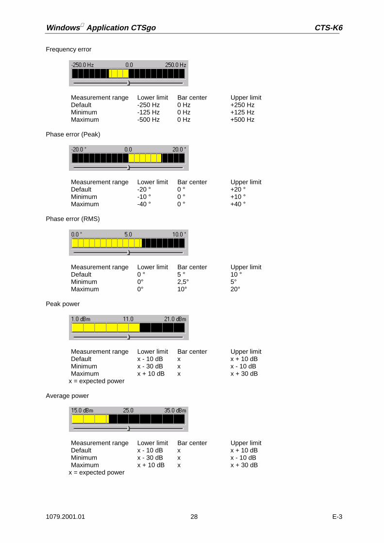
Windows Application CTSgo CTS-K6
1079.2001.01 28 E-3
Frequency error
Phase error (Peak)
Phase error (RMS)
Peak power
x = expected power
Average power
x = expected power
Measurement range Lower limit Bar center Upper limitDefault -250 Hz 0 Hz +250 HzMinimum -125 Hz 0 Hz +125 HzMaximum -500 Hz 0 Hz +500 Hz
Measurement range Lower limit Bar center Upper limitDefault -20 ° 0 ° +20 °Minimum -10 ° 0 ° +10 °Maximum -40 ° 0 ° +40 °
Measurement range Lower limit Bar center Upper limitDefault 0 ° 5 ° 10 °Minimum 0° 2,5° 5°Maximum 0° 10° 20°
Measurement range Lower limit Bar center Upper limitDefault x - 10 dB x x + 10 dBMinimum x - 30 dB x x - 10 dBMaximum x + 10 dB x x + 30 dB
Measurement range Lower limit Bar center Upper limitDefault x - 10 dB x x + 10 dBMinimum x - 30 dB x x - 10 dBMaximum x + 10 dB x x + 30 dB

CTS-K6 Windows Application CTSgo
1079.2001.01 29 E-3
The graphics display next to the display of the average power informs the user on whether themeasured values are within the GSM tolerance mask.
Measured values within tolerance mask.
Measured values outside tolerance mask.
Tolerance mask not evaluated.
CTSgo will not evaluate tolerances in the module test when the peak power measurement is the onlyone active. The expected power for the power measurement and other parameters influencing theburst analysis can be entered in a dialog which is displayed when the Burst analysis button is pressed.With the Freeze button, the numeric and the graphics result display are frozen, ie the displayed valuesare not updated. Remote control is however not interrupted. This status is terminated with the Continuebutton.
The Power ramp buttonpermits to display apopup window with thedisplay of the powerramp. The graph showsthe power versus the bitposition. The CTSmeasures the powerwith fourfold oversamp-ling so that fourmeasured values(quarter bits) arerecorded within the timeframe for one bit. Nextto the power ramp thatis shown as a bluecurve, the tolerancemask is displayed asred curve. Since noPCL is known in themodule test, the displaymay slightly differcompared with theautotest measurement.If the average power isnot measured inparallel, the lowesttolerance lines are notdisplayed.
Fig.: Popup menu in GSM module test dialog

Windows Application CTSgo CTS-K6
1079.2001.01 30 E-3
The Phase error buttondisplays a popupwindow with the displayof the phase curveversus the bit positionwithin the ramp. TheCTS also measures thephase with fourfoldoversampling.
By pressing the IQspectrum button, youcan select theoperating mode forviewing the spectrumwithin a GSM channel,which is also called“Narrow Spectrum” or“IQ spectrum“ . As withburst analysis orgenerator mode, 10parameter sets areavailable. The keypadcontains ten buttons IQSpectrum 01 to IQSpectrum 10, the leftblock displays thechannel, the averagingfactor, the expectedpower at the input ofthe CTS, the expectedwaveform and the se-lected filter bandwidth.
Typically, an output sig-nal of a mobile modu-lated with a 0s or 1ssequence is measuredwithout signaling in thisoperating mode. In this
case, the signal carrier features a 67.7-kHz offset from the middle of the channel due to the GMSKmodulation. The RF signal on the suppressed carrier and on the other sideband should be as low aspossible.
Fig.: Popup menu in GSM module test dialog
Fig.: Popup menu in GSM module test dialog

CTS-K6 Windows Application CTSgo
1079.2001.01 31 E-3
Three markers (M1 to M3) are displayed at the points that are typical for this measurement; in additionto the absolute level, the differences from the marker with the highest level are also displayed below.The level scale is relative to the reference level of the tester, the reference level itself is indicated atthe top left of the window.
The window with the graphics display of the phase and power ramp within a burst or the IQ spectrumcan be increased or reduced at will.
When the program is in stop mode, CTSgo can be terminated by pressing the End button or theoperating mode of the CTSgo program changed by pressing the Return to Autotest button.
The operating status of CTS is indicated in the status bar. The icons have the following meaning:
“Red lamp“. Parameter setting is not yet terminated, generator setting and burst analysis are notcorrectly performed.
„Green lamp“. Parameter setting is terminated, generator settings are valid and the burst analysisor IQ spectrum measurement is in progress.
6.4.1 Sequence Control of Module Test
When the module test is called, the sequence control is automatically started. The configurations forRF generator and burst analysis can be entered in parallel and are considered in the program when theentries are confirmed. You may also influence the sequence control in the same way as described forthe sequence control in the autotest.

Windows Application CTSgo CTS-K6
1079.2001.01 32 E-3
6.4.2 Structure of Module Test
Setting of RFgenerator
parameter set
CTS basic configuration
Setting of network and attenuation
Setting of operating mode
yes
RF generator RF burst analysis IQ spectrum
Settingvalid ?
Network,attenuation
valid ?
no
no
yes
Setting of IQspectrum
parameter set
yes
Settingvalid ?
Network,attenuation
valid ?
no
no
yes
Setting of RFanalyzer parameter
set
Perform IQspectrum
measurement
Determination ofphase curve
graphics
Settingvalid ?
Powermeasurement
determination ofgraphics
Settingvalid ?
Burst analysisPerforming scalar
measurements
Settingvalid ?
Network,attenuation
valid ?
yes
yes
yes
no
no
no
yes
no
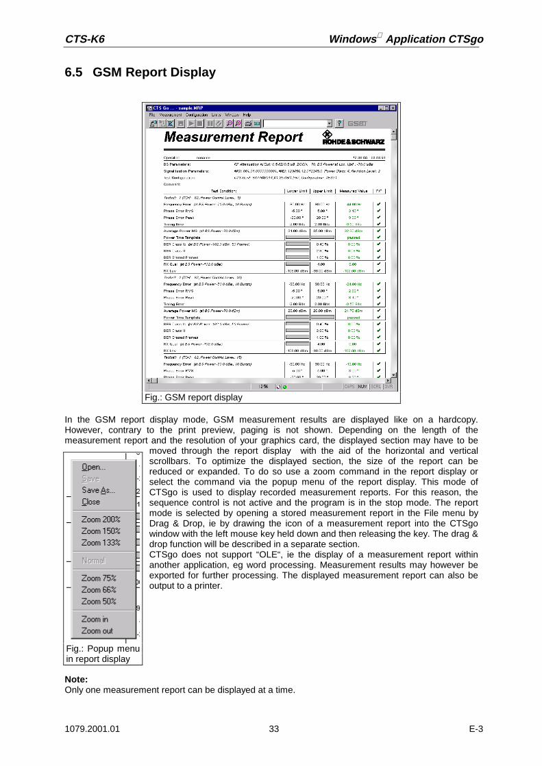
CTS-K6 Windows Application CTSgo
1079.2001.01 33 E-3
6.5 GSM Report Display
In the GSM report display mode, GSM measurement results are displayed like on a hardcopy.However, contrary to the print preview, paging is not shown. Depending on the length of themeasurement report and the resolution of your graphics card, the displayed section may have to be
moved through the report display with the aid of the horizontal and verticalscrollbars. To optimize the displayed section, the size of the report can bereduced or expanded. To do so use a zoom command in the report display orselect the command via the popup menu of the report display. This mode ofCTSgo is used to display recorded measurement reports. For this reason, thesequence control is not active and the program is in the stop mode. The reportmode is selected by opening a stored measurement report in the File menu byDrag & Drop, ie by drawing the icon of a measurement report into the CTSgowindow with the left mouse key held down and then releasing the key. The drag &drop function will be described in a separate section.CTSgo does not support “OLE“, ie the display of a measurement report withinanother application, eg word processing. Measurement results may however beexported for further processing. The displayed measurement report can also beoutput to a printer.
Note:Only one measurement report can be displayed at a time.
Fig.: GSM report display
Fig.: Popup menuin report display

Windows Application CTSgo CTS-K6
1079.2001.01 34 E-3
6.6 DECT Autotest Dialog
The autotest dialog in DECT mode does not considerably differ from the one in GSM mode. Dependingon the operating mode previously used, the operating mode GSM autotest or DECT autotest will beactive with the next program start of CTSgo. For the structure of the autotest dialog refer to the sectionGSM Autotest. The DECT autotest comprises the test of the Fixed Part, FP for short, and the test ofthe Portable Part , PP for short. The Fixed Part test is started with, since the RFPI can be requestedfrom the base station in this test. For testing the Portable Part, the RFPI must already be known. TheRadio Fixed Part Identity is the unambiguous identification number of the fixed part. As the CTS playsthe role of the Fixed Part in the Portable Part Test, it must know the RFPI to be able to address thePortable Part.
Fig.: CTSgo in GSM Module Test Mode

CTS-K6 Windows Application CTSgo
1079.2001.01 35 E-3
6.6.1 Structure of DECT Auto Test
Power measurement graphics/scalar, checking the template
Power/phase/frequency error measurements
Reduction of power to BER level
Determination of BER and FER
Call clear-down
Modulation measurement graphics/scalar, measuring drift, jitter
CTS basic configuration
Preparation of tests PP / FP configuration part 1
Query of RFPI of FP / Setting RFPI in the tester
FP or PP configuration part 2 (Carrier,Slot,Offset)
Call setup in LOOP mode
yes
Echo testactivated
?
no
Power measurement graphics/scalar, checking the template
Call clear-down
Call setup in ECHO mode
Furthertest set
activated
?
noyes
Test evaluation

Windows Application CTSgo CTS-K6
1079.2001.01 36 E-3
6.7 DECT Report Display
The DECT report display mode indicates the DECT measurement results. The DECT report displaycorresponds to the GSM report display concerning the popup menu and the other characteristics.
Note:Depending on whether GSM report or DECT report is loaded, CTSgo will change the type of displayaccordingly.
Fig.: DECT report display mode

CTS-K6 Windows Application CTSgo
1079.2001.01 37 E-3
7 Program MenusThis section describes the commands available in the CTSgo menus. If a command can also be calledvia the toolbar, its icon is displayed below the headline. A command can also be called via a popupmenu when the following line is displayed below the headline.
Popup menus are context-sensitive, ie they only contain commands that are relevant to the currentprogram status.
7.1 File Menu
7.1.1 Open
With this command, a stored measurement report is opened. A dialog is displayed where the desiredfile can be selected. You may have to change the directory in this dialog window. After the selection ofa measurement report, the program changes to the report display mode. Measurement reports arenormally stored in files with the extension .MRP on the hard disk or any other storage medium. Theprogram automatically differentiates between DECT measurement reports and GSM measurementreports.
7.1.2 Close
This command permits to return from the report display mode to the autotest or module test mode. Ifthe displayed measurement report is not yet stored, the user will be prompted to do so.
Popup menu Module test Popup menu Report displayPopup menu Autotest
Fig.: File menu
Popup menu Report display
Popup Menu Report display

Windows Application CTSgo CTS-K6
1079.2001.01 38 E-3
7.1.3 Save
This command can be used to store a measurement report. A dialog window is opened where thedirectory can be selected and the report stored under the desired name.
7.1.4 Save As
This command is similar to the Save command. It allows a saved report to be stored under anothername.
Popup menu Report display
Popup menu Report display
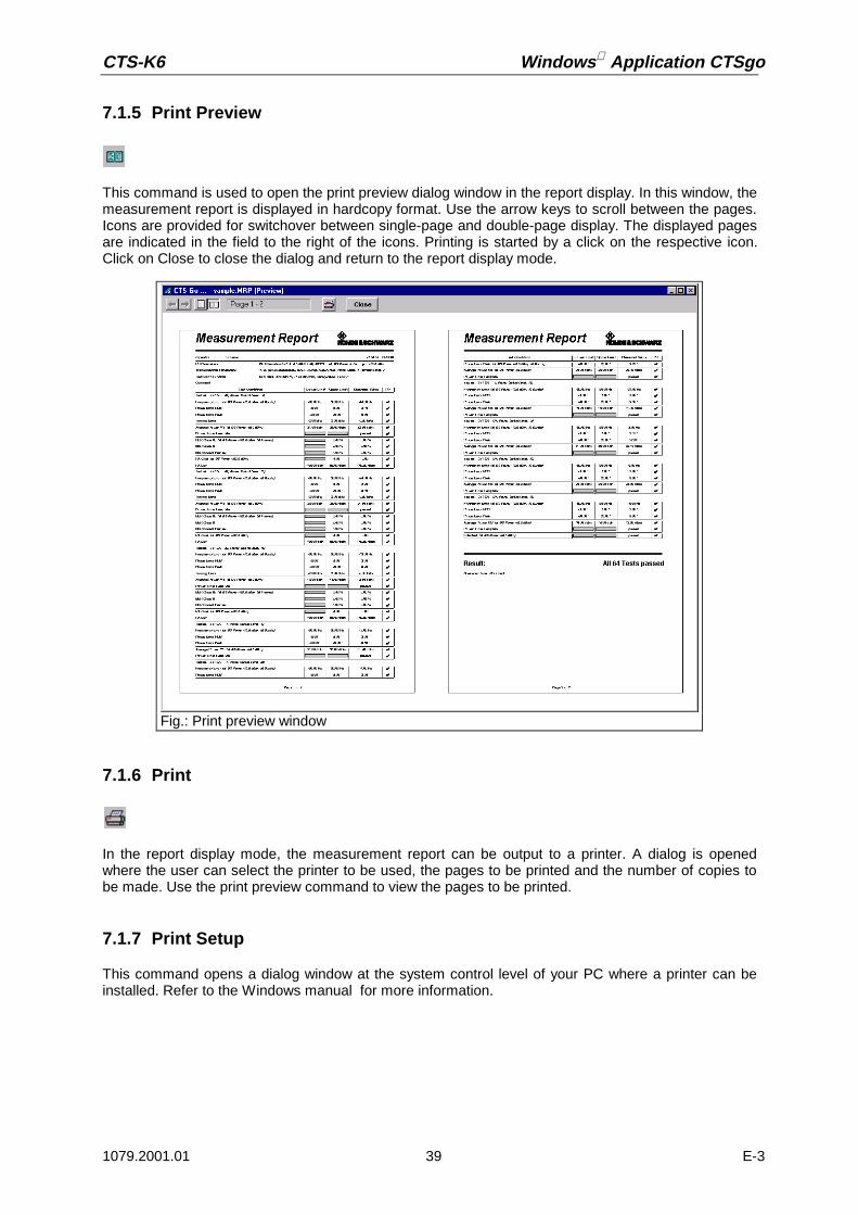
CTS-K6 Windows Application CTSgo
1079.2001.01 39 E-3
7.1.5 Print Preview
This command is used to open the print preview dialog window in the report display. In this window, themeasurement report is displayed in hardcopy format. Use the arrow keys to scroll between the pages.Icons are provided for switchover between single-page and double-page display. The displayed pagesare indicated in the field to the right of the icons. Printing is started by a click on the respective icon.Click on Close to close the dialog and return to the report display mode.
7.1.6 Print
In the report display mode, the measurement report can be output to a printer. A dialog is openedwhere the user can select the printer to be used, the pages to be printed and the number of copies tobe made. Use the print preview command to view the pages to be printed.
7.1.7 Print Setup
This command opens a dialog window at the system control level of your PC where a printer can beinstalled. Refer to the Windows manual for more information.
Fig.: Print preview window

Windows Application CTSgo CTS-K6
1079.2001.01 40 E-3
7.1.8 Export Data
The user may want to work with a measurement report in another Windows application.To do so, select this command to open a dialog window where the desired directory can be selectedand the file assigned a new name. The standard extension of export data is .DAT. Data are stored intabulated form. Columns are separated by a tabulator, rows by carriage return (CR). Since the numberformat may differ from country to country, numerals are stored in the format selected in your operatingsystem. The measurement reports can thus be read as a word file but also by spreadsheet programsor data bases.
Note:If the number format is set incorrectly in the system control, problems may occur when data areimported. In this case, decimal points are interpreted as commas at 1000s digits. So, measured valueswill be incorrect by several orders of magnitude. This should be borne in mind particularly whentransferring data from German-speaking to English-speaking countries.
7.1.9 Application Mode
This command opens a dialog window where the GSM autotest and GSM module test or the DECTautotest can be selected. Click on Cancel to remain in the presently active mode.
Note:The report display mode is activated by selecting the Open command in the File menu.
7.1.10 Load Configuration
All set configurations can be saved for subsequent use. With this command, saved configuration filescan be loaded. Configuration files are assigned the extension .CFG.
NoteThe previously used configurations can also be selected in the popup menu using the righthand mousekey.
Fig.: Application mode dialog window
Popup menu Module testPopup menu Autotest

CTS-K6 Windows Application CTSgo
1079.2001.01 41 E-3
7.1.11 Save Configuration
This command saves the set configuration. A dialog window is opened where the directory can beselected and the configuration stored under the desired file name. Configuration files are assigned theextension .CFG.
7.1.12 Exit
This command is used to terminate the CTSgo program.
Popup menu Module testPopup menu Autotest

Windows Application CTSgo CTS-K6
1079.2001.01 42 E-3
7.2 Measurement Menus
7.2.1 Report Settings
This command opens the following dialog window:
Enter the operator name in the first input field. The name will be stored and displayed in the header ofthe measurement report. A comment can be optionally included in the measurement report. It can beentered in the second input field. Three scenarios are possible when the measurement is terminated:
• Display: All tests passed – Some tests failed. A measurement report is not generated as standard.After termination of the autotest, a small dialog window is opened where you can decide on whetherto continue with the next test run or view another measurement report. Use this option for shorttests only where only the All tests passed – Some tests failed statement is of importance.
Fig.: Measurements menu in the GSMautotest, DECT autotest Fig.: Measurements menu in the GSM
module test
Fig.: Report settings dialog window

CTS-K6 Windows Application CTSgo
1079.2001.01 43 E-3
• Automatic generation of a measurement report. After the measurement, the program remains in theautotest dialog mode. “All tests passed – Some tests failed.” is displayed. A measurement report issaved in a user-selected directory. Measurement reports are stored with consecutive numbers„00000001.MRP“ „00000002.MRP“ etc. Like in the preceding mode, a small dialog window appears,where a measurement report can be displayed or the tests continued.
• At the end of the measurements, the CTSgo program automatically changes to the report displaymode. The name and directory for storing the measurement report are then defined by the user inthe File menu. This menu also contains the command for printing the measurement report.
Select the desired setting by choosing the respective option.Enter the path for automatic storage of measurement reports in the associated input field. Duringprogram installation, the subdirectory AUTOSAVE is created as standard.
A graph is displayed at the right in the header of the measurement report. You may use the logo ofyour company instead of the Rohde & Schwarz logo. Within certain limits, the program tries to adaptyour logo to the header of the measurement report. Optimum results can be obtained with graphicsfiles with the following characteristics:
• Width: 900 pixels• Height: 220 pixels• Black/white• Format: Windows bit map (BMP)
A file is selected in the dialog window opened with “Browse”. The “User-defined Bit Map” box“ ischecked and the graph is displayed in the preview field above.
Important:To keep the measurement report file as small as possible, the picture file is not stored in the report butmerely its name. Depending on the directory in which the picture file has been stored, the file name isstored independently or with reference to the CTSgo directory. For copying measurement report filesfrom one computer (A) to another (B), the following examples should be observed.
Storage using a relative path:
The path of the picture file is considered relative when the file is stored in the current directory or in asubdirectory of CTSgo.
Example:The measurement report is stored in computer A:
Current directory: C:\CTSGO\Picture file: C:\CTSGO\BITMAPS\USER.BMP
To display the measurement report on Computer B:
Current directory: C:\MYWORKS\CTSGO\Picture file: C:\MYWORKS\CTSGO\BITMAPS\USER.BMP
Storage using an absolute path:
The path of the picture file is considered absolute when the current directory of CTSgo is not part of thepicture file path.

Windows Application CTSgo CTS-K6
1079.2001.01 44 E-3
Example:The measurement report is stored in computer A:
Current directory: C:\CTSGO\Picture file: C:\BITMAPS\USER.BMP
To display the measurement report on computer B:
Current directory: C:\MYWORKS\CTSGO\Picture file: C:\BITMAPS\USER.BMP
These settings concern both the GSM and the DECT autotest.
7.2.2 Start
The Start command is used to start a new measurement.
7.2.3 Stop
The Stop command is used to stop the current measurement. The program returns to the beginning ofthe autotest. The previously performed test is not output. All obtained measurement results are lost.
7.2.4 Pause
The Pause command permits to interrupt the program run. The currently performed step of theautotest is completed before the sequence control stops the test. Another click on Pause continues themeasurement.
7.2.5 Step
This command permits to check the sequence control of the autotest step by step. After each singlestep, the program automatically goes to the pause mode.
7.2.6 Freeze
The Freeze command permits to freeze the numeric and graphics result display in the module test, iedisplayed values are not updated. This does not interrupt remote control.
7.2.7 Continue
With this command, freezing of the result display in the module test is cancelled. The displayed valuesare continuously updated again.
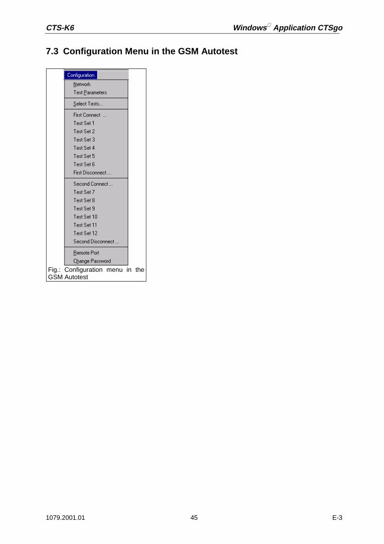
CTS-K6 Windows Application CTSgo
1079.2001.01 45 E-3
7.3 Configuration Menu in the GSM Autotest
Fig.: Configuration menu in theGSM Autotest

Windows Application CTSgo CTS-K6
1079.2001.01 46 E-3
7.3.1 Network
This command opens the Configure Network dialog window. In this window, the measurements can beadapted to the network of your mobile. The base station power at which the mobile performs a locationupdate is also set here.
After switching on, the mobile searches in all channels for a base-station carrier, also called C0 carrier.A component of the C0 carrier is the broadcast channel, also called BCCH. The mobile synchronizes tothis carrier and compares the decoded data from the base station with the data on the SIM card. It thenregisters with the base station. This registration is called location update. If the output power is too low,your mobile may not register with the base station simulated by the CTS. Changing from GSM 900 toGSM 1800 or GSM 1900 may cause PCL steps 16 to 19 to be cleared from the test set and replacedby PCL step 15. In this case, a warning is output by CTSgo.
Dualband-Mobiles are able to use channels of the GSM 900 band as well as channels of the GSM1800 band. You decide the primary network and the handover network. The primary network is theone, which is used for the BCCH generation. This means, that the network is used for location updateand the call process. A channel change from one band to another band is called dualband handover.Check the box “Handovercheck“, if you want the testset to use the signalisation for checking thedualband handover capabilities of your mobile. You have to check the box “BCCH remains afterhandover“, if your mobile needs a remaining BCCH signal in the primary network, when changing tothe secondary band. A missing BCCH signal will result in a higher frequency error after dualbandhandover. There are some mobiles, which have the capability to handover between GSM 900 andGSM 1900. Due to the geographical distance, there is no existing GSM 900 / 1900 dualband handoverimplemented in the network. On some mobile it can be used for test purposes. The method is thesame, as it is for GSM 900 / 1800 dualband handover.
Fig.: Configure Network dialog window
Fig.: Warning of network configuration

CTS-K6 Windows Application CTSgo
1079.2001.01 47 E-3
Note:The choice of networks depends on the options available in your CTS!It is advisable to configure the network first and then make test configurations.
7.3.2 Test Parameters
The Test Parameters command opens the dialog window shown below. This window permits to set theBCCH of the base station, the path attenuation between mobile and CTS, the number of frames usedfor the bit-error-rate measurement and the number of bursts for the phase and frequency-errormeasurement.
The input of correct attenuation values has a decisive influence on the measurement accuracy. In theideal case, an antenna cable should be used, which is directly connected to the mobile, eg as found inthe car kit of the mobile. An attenuation between 0.5 and 2 dB is normally obtained in this case.Problems will however arise when using antenna couplers. The attenuation of the mobile types maydiffer considerably, and it may vary depending on the frequency channel used. If you do not know theattenuation of your antenna coupler proceed as described below:
• Establish a connection to your mobile in the manual mode of CTS.• Set a power of eg –70 dBm for the traffic channel TCH.• Measure RXLev. This is the power the mobile receives, which is signaled to the base station at
regular intervals in so-called measurement reports.• Compare the measured RXLev with the TCH power of the CTS.• Select an average power control level (PCL) on the CTS.• Compare the measured output power of the mobile with the rated value of the selected PCL.
The input of the attenuation values happens independently for each band. The attenation values foreach band are separated for low, mid and high channels.
Bear in mind that, in addition to the measurement inaccuracy of the tester, the production tolerance ofthe mobile has to be taken into account to estimate the total error. This method requires the mobile tobe fully operational.The BER measurement is the only way to determine the receiving quality and particularly the sensitivityof the mobile. The measurement itself is a statistical evaluation of the sent bits and the errored bits.
Fig.: Configure Test Parameters dialog window

Windows Application CTSgo CTS-K6
1079.2001.01 48 E-3
More reliable results are obtained by increasing the frames and thus the number of bits, but thisextends the measurement time.
Note:The measurement time for the phase/frequency error measurement also depends on the number ofbursts to be considered.
7.3.3 Select Tests
This command opens the Select Tests dialog window. By checking the respective boxes you decidewhether the call is set up and cleared down once or twice during the test. You also select the numberof test sets used. By default up to six test sets can be selected for each connection. Using the up /down arrow buttons, you can change the position for the second connection inside the testplan.
Fig.: Select Tests dialog window

CTS-K6 Windows Application CTSgo
1079.2001.01 49 E-3
7.3.4 First Connect
This command permits to define the method for the first call setup. To this end, select whether theCTSgo program expects a call from the mobile or whether the call should be set up by the CTS. In thecase of a mobile call, you can define an expected numerical entry, which will then be compared withthe call number received and evaluated in the test report. Thus the number keys of the mobile can alsobe easily checked.
Note:This command can only be selected if the first connection is activated for the test.
7.3.5 Test Set 1
You can decide for each test set which measurements should be performed in a traffic channel (TCH).To do so enter the TCH to be used in the first entry field. Select the measurements to be performedfrom the list at the right. Enter the RF output power of the CTS (BS power) for the individual tests inthe entry fields “Standard“ and “BER“.
Fig.: Configure first Connect dialog window

Windows Application CTSgo CTS-K6
1079.2001.01 50 E-3
The standard BS output power is used for the following measurements:
• Frequency error• Phase error (RMS and peak value are determined numerically)• Phase error (phase error curve within burst)• Bit timing• Average burst power• Graphics display of power ramp• Echo test
The BER base-station power is used for the remaining measurements:
• BER class Ib• BER class II• BER EFR (Erased Frames)• RXQual• RXLev
The measurements are repeated at all power levels (PCLs) selected in the boxes.As an option, the test set can be assigned a short name, which will also be displayed in the menu.The graphics display of power ramp and phase error is shown in the appendix when the measurementreport is generated. E-GSM channels are part of network GSM900. The attenuation values shown inthis dialog are channel depending. These values are only shown for your information.
Note:This command can only be selected if test set 1 is activated for the test.
Fig.: Configure Test Set dialog window

CTS-K6 Windows Application CTSgo
1079.2001.01 51 E-3
7.3.6 Test Set 2
You can determine the measurements to be performed in the selected TCH channels. For details referto the description under Test set 1.
Note:This command can only be selected if Test set 2 is activated for the test.
7.3.7 Test Set 3
You can determine the measurements to be performed in the selected TCH channels. For details referto the description under Test set 1.
Note:This command can only be selected if Test set 3 is activated for the test.
7.3.8 Test Set 4
You can determine the measurements to be performed in the selected TCH channels. For details referto the description under Test set 1.
Note:This command can only be selected if Test set 4 is activated for the test.
7.3.9 Test Set 5
You can determine the measurements to be performed in the selected TCH channels. For details referto the description under Test set 1.
Note:This command can only be selected if Test set 5 is activated for the test.
7.3.10 Test Set 6
You can determine the measurements to be performed in the selected TCH channels. For details referto the description under Test set 1.
Note:This command can only be selected if Test set 6 is activated for the test.

Windows Application CTSgo CTS-K6
1079.2001.01 52 E-3
7.3.11 First Disconnect
Using this command you can determine the procedure for the first call clear-down. Select by a click onthe respective box whether a call release is expected from the mobile or whether the call should becleared down by the CTS.
Note:This command can only be selected if the first connection is activated for the test.
7.3.12 Second Connect
This command permits to select the procedure for the second call clear-down. Select by a click on therespective box whether the CTSgo program expects a call from the mobile or whether the call shouldbe set up by the CTS.
Note:This command can only be selected if the second connection is activated for the test.
7.3.13 Test Set 7
You can determine the measurements to be performed in the selected TCH channel. For details referto the description under Test set 1.
Note:This command can only be selected if test set 7 is activated for the test.
7.3.14 Test Set 8
You can determine the measurements to be performed in the selected TCH channel. For details referto the description under Test set 1.
Note:This command can only be selected if test set 8 is activated for the test.
Fig.: Configure Disconnect dialog window

CTS-K6 Windows Application CTSgo
1079.2001.01 53 E-3
7.3.15 Test Set 9
You can determine the measurements to be performed in the selected TCH channel. For details referto the description under Test set 1.
Note:This command can only be selected if test set 9 is activated for the test.
7.3.16 Test Set 10
You can determine the measurements to be performed in the selected TCH channel. For details referto the description under Test set 1.
Note:This command can only be selected if test set 10 is activated for the test.
7.3.17 Test Set 11
You can determine the measurements to be performed in the selected TCH channel. For details referto the description under Test set 1.
Note:This command can only be selected if test set 11 is activated for the test.
7.3.18 Test Set 12
You can determine the measurements to be performed in the selected TCH channel. For details referto the description under Test set 1.
Note:This command can only be selected if test set 12 is activated for the test.
7.3.19 Second Disconnect
Using this command you can determine the procedure for the second call clear-down. Select by a clickon the respective box whether a call release is expected from the mobile or whether the call should becleared down by the CTS.
Note:This command can only be selected if the second connection is activated for the test.

Windows Application CTSgo CTS-K6
1079.2001.01 54 E-3
7.3.20 Remote Port
To ensure error-free functioning of the CTSgo software, the settings made for the remote controlinterface (RS232) should match the settings on the CTS.The parameters of the serial interface such as baud rate, data bits used, stop bits, parity used and theprotocol can be selected on the CTS. Adapt the settings of CTSgo to those of CTS by checking therespective box. The serial interface of your PC and the command line terminator should also be set.<CR>+<LF> should normally be used.
The timeout of the CTS for responding to a query should now be defined. This parameter depends onthe configuration of the individual tests. See also the note for the Test Parameters command.
Note:In the case of a CTS30 the parameters of the serial interface are set as follows:
• Baud rate 38400• 8 data bits• 1 stop bit• Parity None• Protocol CTS/RTS
Fig.: Remote port dialog window

CTS-K6 Windows Application CTSgo
1079.2001.01 55 E-3
7.3.21 Change Password
Your configuration can be protected against unauthorized changes. To this end, enter a password inthe first field and repeat it in the next. The password function is activated by selecting the “Activate”box.
Each time a configuration command of the program menus is selected, you will then be prompted toenter this password. After entering a correct password, changes can be made in the configuration untilthe sequence control of the program is started.
The password mainly serves for preventing inadvertent changes being made to your data and does notprovide 100% protection. In case you have forgotten the password, clear the entry in the initializationfile ”CTS_GO.INI“
Fig.: Change Password dialog window
Fig.: Enter Password dialogwindow
Fig.: Configuration menu inGSM module test

Windows Application CTSgo CTS-K6
1079.2001.01 56 E-3
7.4 Configuration Menu in the GSM Module Test
7.4.1 Attenuation
In the module test, this dialog permits to standardize the attenuation values of the parameter sets ingenerator, burst analysis and IQ spectrum mode. After entering the input attenuation and outputattenuation, close the dialog window by clicking on OK. In another dialog window, you will be promptedwhether you really want to overwrite all parameter sets with these values. Click on Yes if you are reallysure about it, otherwise select No.
7.4.2 Generator Settings
The Configurations menu includes the Generator Settings submenu, where the menu items “RFGenerator 1” to “RF Generator 10” can be found. Select one of these commands in order to edit thedesired generator parameter set.The CTS provides an RF signal. The parameters of this RF signal are set in this dialog window. In thefirst field, the transmission channel of the CTS is entered, in the second the frequency offset to thefixed GSM frequency grid of 200 kHz. The CTS output power can be set in the third field. This power ispresent at the selected RF connector “RF In/Out“ or “RF Out 2“. A click on “Generator on“ decideswhether the RF generator sends the set signal or not. With “Bitmodulation on” you can decide whethera midamble is included in the signal or not. In the fourth field, the training sequence (TSC) of themidamble is defined. With “Ramp on” you can decide whether the RF signal is with or without a burst.
Fig.: Configure Test Parameters dialog window

CTS-K6 Windows Application CTSgo
1079.2001.01 57 E-3
Whether the channel or the frequency is entered is selected with the Channel Input box. If frequency isentered, it is adapted to the channel and frequency offset.
The entered channel or the conversion to the respective frequency also depends on the currentlyactive network. Channels and associated frequencies are listed in the tables below. Channels outsidethe currently used band are displayed on a dark background.
Fig.: RF Generator Settings dialog window
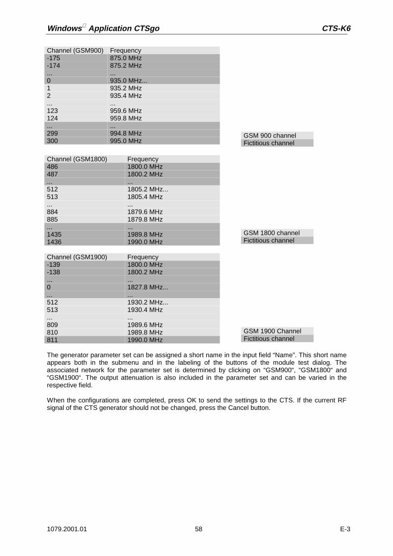
Windows Application CTSgo CTS-K6
1079.2001.01 58 E-3
The generator parameter set can be assigned a short name in the input field “Name”. This short nameappears both in the submenu and in the labeling of the buttons of the module test dialog. Theassociated network for the parameter set is determined by clicking on “GSM900“, “GSM1800“ and“GSM1900“. The output attenuation is also included in the parameter set and can be varied in therespective field.
When the configurations are completed, press OK to send the settings to the CTS. If the current RFsignal of the CTS generator should not be changed, press the Cancel button.
Channel (GSM900) Frequency-175 875.0 MHz-174 875.2 MHz... ...0 935.0 MHz...1 935.2 MHz2 935.4 MHz... ...123 959.6 MHz124 959.8 MHz... ...299 994.8 MHz300 995.0 MHz
GSM 900 channelFictitious channel
Channel (GSM1800) Frequency486 1800.0 MHz487 1800.2 MHz... ...512 1805.2 MHz...513 1805.4 MHz... ...884 1879.6 MHz885 1879.8 MHz... ...1435 1989.8 MHz1436 1990.0 MHz
GSM 1800 channelFictitious channel
Channel (GSM1900) Frequency-139 1800.0 MHz-138 1800.2 MHz... ...0 1827.8 MHz...... ...512 1930.2 MHz...513 1930.4 MHz... ...809 1989.6 MHz810 1989.8 MHz811 1990.0 MHz
GSM 1900 ChannelFictitious channel

CTS-K6 Windows Application CTSgo
1079.2001.01 59 E-3
7.4.3 Burst Analysis Settings
The Configurations menu includes the Burst Analysis Settings submenu, where the menu items “RFAnalyzer 1” to “RF Analyzer 10” can be found. Select one of these commands for editing the respectiveburst analysis parameter set.This command permits to set the module test parameters in the Configure Burst Analysis dialogwindow. In the first field, enter the channel of the signal to be evaluated, in the second the expectedtraining sequence of the midamble. With GSM, the training sequences are used for timesynchronization of the received bit sequence. Since this sync bit sequence is in the middle of the burstit is called midamble.In the third field, the expected power can be entered. This setting is signaled to the CTS. The dynamicrange of the graphics result display for power measurements also depends on these settings. Thetrigger mode can be selected by a click on the desired option.
Power:The signal must be a burst signal with a midamble. It is triggered on the incoming power.
Freerun: The signal to be measured must contain a midamble to allow the CTS to synchronize.
By activating the Channel Input box, you can change between channel and frequency input. If thefrequency is entered, it it adapted to the GSM channel spacing.
Fig.: Configure Burst Analysis dialog window

Windows Application CTSgo CTS-K6
1079.2001.01 60 E-3
The entered channel or the conversion to its frequency also depends on the currently active network.Channels and associated frequencies are listed in the tables below. Channels outside the currentlyused band are displayed on a dark background.
The burst analysis parameter set can be assigned a short name in the Name field. This short nameappears both in the submenu and in the labeling of the buttons of the module test dialog. Theassociated network for the parameter set is determined by clicking on “GSM900“, “GSM1800“ and“GSM1900“. The input attenuation is also included in the parameter set and can be varied in therespective field.
Channel (GSM900) Frequency-75 875.0 MHz-74 875.2 MHz... ...0 890.0 MHz...1 890.2 MHz2 890.4 MHz... ...123 914.6 MHz124 914.8 MHz... ...449 979.8 MHz450 980,0 MHz
GSM 900 KanalFictitious channel
Channel(GSM1800)
Frequency
461 1700.0 MHz462 1700.2 MHz... ...512 1710.2 MHz...513 1710.4 MHz... ...884 1784.6 MHz885 1784.8 MHz... ...1510 1909.8 MHz1511 1910.0 MHz
GSM 1800 KanalFictitious channel
Channel(GSM1900)
Frequency
-239 1700.0 MHz-238 1700.2 MHz... ...0 1747.8 MHz...... ...512 1850.2 MHz...513 1850.4 MHz... ...809 1909.6 MHz810 1909.8 MHz811 1910.0 MHz
GSM 1900 channelFictitious channel
CTS-K6 Windows Application CTSgo
1079.2001.01 61 E-3
As a particular feature of the configuration dialog for burst analysis, you can force a certain displaymode. When this configuration set is called later on, the popup windows of burst analysis will beopened or closed, certain measurements marked or some marking cleared. Select the desired displaymode and make a mark the “Force Displaymode” box in this dialog window.
After completing all the configurations, press OK to send the settings to the CTS. If you do not want tochange the currently active burst analysis settings of the CTS click on Cancel.

Windows Application CTSgo CTS-K6
1079.2001.01 62 E-3
7.4.4 IQ Spectrum Settings
The Configurations menu includes the submenu “IQ Spectrum Settings”. This submenu contains themenu items “IQ Spectrum 1” to “IQ Spectrum 10”. Select one of these commands to edit an IQspectrum parameter set.This command permits to set module test parameters in the dialog window “IQ Spectrum Settings“ . Inthe first field enter the channel of the signal to be evaluated, in the second the averaging factor, ie thenumber of burst for averaging. The expected power is entered in the third field and then signaled to theCTS. Besides, the dynamic range of the graphics result display for the power measurements dependson the selected setting. In the first field of the dialog window, you can enter whether a ramped or acontinuous input signal is expected.
CW:„Continuous Wave“, ie a signal with continuous power and without power ramp.
Burst: The signal to be measured has a power ramp.
In the second field of the dialog, the used bandwidth of the input filter is entered. The following settingsare available:
• 4 kHz• 10 kHz• 20 kHz• 50 kHz• 100 kHz
Fig.: Configure IQ Spectrum dialog window

CTS-K6 Windows Application CTSgo
1079.2001.01 63 E-3
By activating the Channel Input box, you can change between channel input and frequency input. If thefrequency is entered, it is adapted to the GSM channel spacing.
The entered channel or the conversion to its frequency also depends on the currently active network.Channels and associated frequencies are listed in the tables below. Channels outside the currentlyused band are displayed on a dark background.
Channel (GSM900) Frequency-75 875.0 MHz-74 875.2 MHz... ...0 890.0 MHz...1 890.2 MHz2 890.4 MHz... ...123 914.6 MHz124 914.8 MHz... ...449 979.8 MHz450 980.0 MHz
GSM 900 channelFictitious channel
Channel(GSM1800)
Frequency
461 1700.0 MHz462 1700.2 MHz... ...512 1710.2 MHz...513 1710.4 MHz... ...884 1784.6 MHz885 1784.8 MHz... ...1510 1909.8 MHz1511 1910.0 MHz
GSM 1800 channelFictitious channel
Channel(GSM1900)
Frequency
-239 1700.0 MHz-238 1700.2 MHz... ...0 1747.8 MHz...... ...512 1850.2 MHz...513 1850.4 MHz... ...809 1909.6 MHz810 1909.8 MHz811 1910.0 MHz
GSM 1900 channelFictitious channel

Windows Application CTSgo CTS-K6
1079.2001.01 64 E-3
The IQ spectrum parameter set can be assigned a short name in the Name field. This short nameappears both in the submenu and in the labeling of the buttons of the module test dialog window. Theassociated network is determined for the parameter set by clicking on “GSM900“, “GSM1800“ and“GSM1900“ in the respective field. The parameter set also includes the input attenuation which can bevaried in the respective field.
After completing all configurations press OK to send the settings to the CTS. If you do not want tochange the current IQ spectrum settings of the CTS press Cancel.
7.4.5 Remote Port
The same dialog window as for the GSM autotest is displayed. For further information refer to therespective chapter of the GSM autotest.
7.4.6 Change Password
The same dialog window as for the GSM autotest is displayed. For further information refer to therespective chapter of the GSM autotest.

CTS-K6 Windows Application CTSgo
1079.2001.01 65 E-3
7.5 Configuration Menu in the DECT Autotest
7.5.1 PP Base Settings
This command permits to call the “PP Base Settings“ dialog window. Use this dialog to adapt the testmode to the parameters of your portable part. The portable part can only be tested if the RFPI of theDUT is known. Enter this RFPI in the respective field. In order to test a set consisting of portable partand fixed part the RFPI from the FP test can be used. To do so, note the description of the FP basesettings in this manual. In the two following fields, you can enter the channel and the slot of the dummybearer generated by the CTS. The dummy bearer is the carrier to which a portable part is synchronizedafter it has been switched on. The Q-packages of the MAC level are sent from the CTS during the PPtest. These are three binary packages Q0, Q3 and Q6. The associated values can be entered ashexadecimal values. The QMUX indicates the transmission sequence of the packages. A value of“03060306“ means that first a Q0, then a Q3, a further Q0 and then a Q6 package, etc. are sent.Further information on Q-package messages can be obtained from the ETSI standard ETS 300-175Part 3. Finally, for compensation of RF losses, you can enter attenuation values for the input andoutput in the respective. The CTS will then convert its output level and the measured output power ofthe mobile accordingly.
Fig.: Configuration menu in theDECT autotest
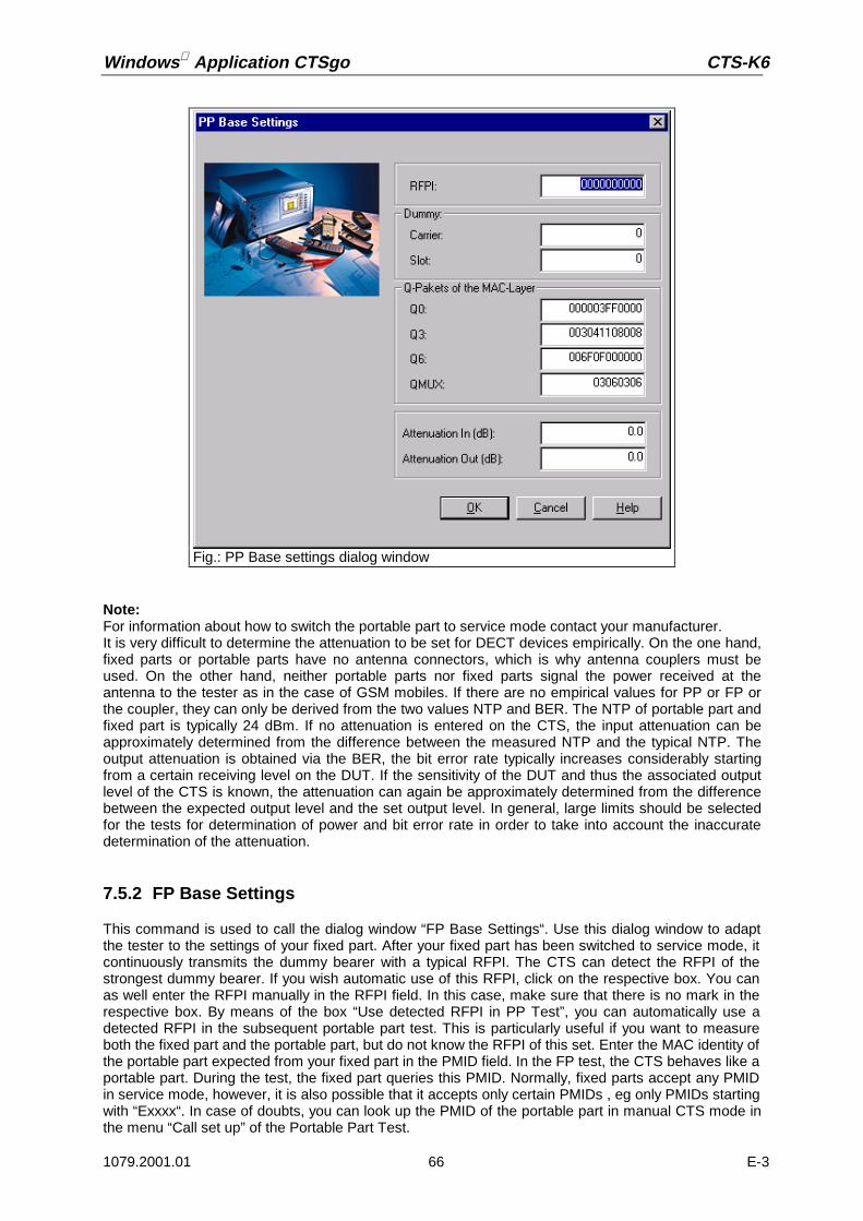
Windows Application CTSgo CTS-K6
1079.2001.01 66 E-3
Note:For information about how to switch the portable part to service mode contact your manufacturer.It is very difficult to determine the attenuation to be set for DECT devices empirically. On the one hand,fixed parts or portable parts have no antenna connectors, which is why antenna couplers must beused. On the other hand, neither portable parts nor fixed parts signal the power received at theantenna to the tester as in the case of GSM mobiles. If there are no empirical values for PP or FP orthe coupler, they can only be derived from the two values NTP and BER. The NTP of portable part andfixed part is typically 24 dBm. If no attenuation is entered on the CTS, the input attenuation can beapproximately determined from the difference between the measured NTP and the typical NTP. Theoutput attenuation is obtained via the BER, the bit error rate typically increases considerably startingfrom a certain receiving level on the DUT. If the sensitivity of the DUT and thus the associated outputlevel of the CTS is known, the attenuation can again be approximately determined from the differencebetween the expected output level and the set output level. In general, large limits should be selectedfor the tests for determination of power and bit error rate in order to take into account the inaccuratedetermination of the attenuation.
7.5.2 FP Base Settings
This command is used to call the dialog window “FP Base Settings“. Use this dialog window to adaptthe tester to the settings of your fixed part. After your fixed part has been switched to service mode, itcontinuously transmits the dummy bearer with a typical RFPI. The CTS can detect the RFPI of thestrongest dummy bearer. If you wish automatic use of this RFPI, click on the respective box. You canas well enter the RFPI manually in the RFPI field. In this case, make sure that there is no mark in therespective box. By means of the box “Use detected RFPI in PP Test”, you can automatically use adetected RFPI in the subsequent portable part test. This is particularly useful if you want to measureboth the fixed part and the portable part, but do not know the RFPI of this set. Enter the MAC identity ofthe portable part expected from your fixed part in the PMID field. In the FP test, the CTS behaves like aportable part. During the test, the fixed part queries this PMID. Normally, fixed parts accept any PMIDin service mode, however, it is also possible that it accepts only certain PMIDs , eg only PMIDs startingwith “Exxxx“. In case of doubts, you can look up the PMID of the portable part in manual CTS mode inthe menu “Call set up” of the Portable Part Test.
Fig.: PP Base settings dialog window

CTS-K6 Windows Application CTSgo
1079.2001.01 67 E-3
The antenna to be used can be entered in the input field below. The input and output attenuation areentered in two further fields.
Note:For information about how to switch the portable part to service mode contact your manufacturer.It is very difficult to determine the attenuation to be set for DECT devices empirically. On the one hand,fixed parts or portable parts have no antenna connectors, which is why antenna couplers must beused. On the other hand, neither portable parts nor fixed parts signal the power received at theantenna to the tester as in the case of GSM mobiles. If there are no empirical values for PP or FP orthe coupler, they can only be derived from the two values NTP and BER. The NTP of portable part andfixed part is typically 24 dBm. If no attenuation is entered on the CTS, the input attenuation can beapproximately determined from the difference between the measured NTP and the typical NTP. Theoutput attenuation is obtained via the BER, the bit error rate typically increases considerably startingfrom a certain receiving level on the DUT. If the sensitivity of the DUT and thus the associated outputlevel of the CTS is known, the attenuation can again be approximately determined from the differencebetween the expected output level and the set output level. In general, large limits should be selectedfor the tests for determination of power and bit error rate in order to take into account the inaccuratedetermination of the attenuation.
Fig.: FP Base settings dialog window

Windows Application CTSgo CTS-K6
1079.2001.01 68 E-3
7.5.3 Select Tests
This command opens the dialog window below. The number of test sets for the fixed part test and thenumber of test sets for the portable part test are selected using the respective boxes. If you do notwant to perform a fixed part test or a portable part test, clear the respective mark in the box. Up to sixFP test sets and six PP test sets are provided.
Fig.: Select Tests dialog window

CTS-K6 Windows Application CTSgo
1079.2001.01 69 E-3
7.5.4 FP Test Set 1
Within the test sets, you can determine the measurements to be performed for a traffic bearer. To thisend, enter the carrier of the traffic bearer to be used in the first input field. You may as well enter thecarrier offset. In addition, the slot to be used can also be defined in the respective field. Select thetests to be performed within the frames “RX Measurements” and “TX Measurements” by checking therespective boxes.
The assignment of frequencies and channel and offset values can be obtained from the table below:
Chan-
nel
0 1 2 3 4 5 6 7 8 9
Offset -3 1902.528 1900.800 1899.072 1897.344 1895.616 1893.888 1892.160 1890.432 1888.704 1886.976
-2.5 1901.664 1899.936 1898.208 1896.480 1894.752 1893.024 1891.296 1889.568 1887.840 1886.112
-2 1900.800 1899.072 1897.344 1895.616 1893.888 1892.160 1890.432 1888.704 1886.976 1885.248
-1.5 1899.936 1898.208 1896.480 1894.752 1893.024 1891.296 1889.568 1887.840 1886.112 1884.384
-1 1899.072 1897.344 1895.616 1893.888 1892.160 1890.432 1888.704 1886.976 1885.248 1883.520
-0,5 1898.208 1896.480 1894.752 1893.024 1891.296 1889.568 1887.840 1886.112 1884.384 1882.656
0 1897.344 1895.616 1893.888 1892.160 1890.432 1888.704 1886.976 1885.248 1883.520 1881.792
0,5 1896.480 1894.752 1893.024 1891.296 1889.568 1887.840 1886.112 1884.384 1882.656 1880.928
1 1895.616 1893.888 1892.160 1890.432 1888.704 1886.976 1885.248 1883.520 1881.792 1880.064
1.5 1894.752 1893.024 1891.296 1889.568 1887.840 1886.112 1884.384 1882.656 1880.928 1879.200
2 1893.888 1892.160 1890.432 1888.704 1886.976 1885.248 1883.520 1881.792 1880.064 1878.336
2.5 1893.024 1891.296 1889.568 1887.840 1886.112 1884.384 1882.656 1880.928 1879.200 1877.472
3 1892.160 1890.432 1888.704 1886.976 1885.248 1883.520 1881.792 1880.064 1878.336 1876.608
Fig.: Configure DECT FP Test Set 1 dialog

Windows Application CTSgo CTS-K6
1079.2001.01 70 E-3
The following RX measurements are available:
• BER (Bit Error Rate)• FER (Frame Error Rate)
The RF output level of the CTS for these measurements is to be determined in the RF Level field ofRX Measurements. Besides, the number of frames to be sent is determined.
The following TX measurements are available:
• NTP (Normal Transmit Power)• Power ramp (Template)• Graphics burst display in the appendix to the measurement report• Frequency offset• B-field modulation• Graphics display of the modulation in the appendix to the measurement report• Frequency drift• Time accuracy• Jitter• Acoustic echo test
For these measurements, the RF output level of the CTS is to be entered in the RF Level field of TXMeasurements. Besides, the number of bursts to be sent is determined for the power and modulationmeasurement or the number of bursts to be sent for the timing measurement.
Note:This command can only be called if FP test set 1 is activated for the test.
7.5.5 FP Test Set 2
You can determine the tests to be performed for the Traffic Bearer. For details refer to the descriptionof FP Test set 1.
Note:This command can only be called if FP Test set 2 is activated for the test.
7.5.6 FP Test Set 3
You can determine the tests to be performed for the Traffic Bearer. For more details refer to thedescription of FP test set 1.
Note:This command can only be called if FP test set 3 is activated for the test.
7.5.7 FP Test Set 4
You can determine the tests to be performed for the Traffic Bearer. For more details refer to thedescription of FP test set 1.
Note:This command can only be called if FP test set 4 is activated for the test.

CTS-K6 Windows Application CTSgo
1079.2001.01 71 E-3
7.5.8 FP Test Set 5
You can determine the number of tests for the Traffic Bearer. For more details refer to the descriptionof FP test set 1.
Note:This command can only be called if FP test set 5 is activated for the test.
7.5.9 FP Test Set 6
You can determine the tests to be performed for the Traffic Bearer. For more details refer to thedescription of FP test set 1.
Note:This command can only be called if FP test set 6 is activated for the test.

Windows Application CTSgo CTS-K6
1079.2001.01 72 E-3
7.5.10 PP Test Set 1
Within the test sets, you can determine the tests to be performed for a traffic bearer. To do so, enterthe carrier of the traffic bearer to be used in the first input field. You can as well enter the carrier offset.In addition, you can define the used slot in the respective field. Select the tests to be performed for theRF measurements and the TX measurements by checking the respective boxes.
The assignment of frequencies to channel and offset values can be obtained from the table below.Bear in mind that only integral offset values are permissible when testing a portable part.
Chan-
nel
0 1 2 3 4 5 6 7 8 9
Offset -3 1902.528 1900.800 1899.072 1897.344 1895.616 1893.888 1892.160 1890.432 1888.704 1886.976
-2 1900.800 1899.072 1897.344 1895.616 1893.888 1892.160 1890.432 1888.704 1886.976 1885.248
-1 1899.072 1897.344 1895.616 1893.888 1892.160 1890.432 1888.704 1886.976 1885.248 1883.520
0 1897.344 1895.616 1893.888 1892.160 1890.432 1888.704 1886.976 1885.248 1883.520 1881.792
1 1895.616 1893.888 1892.160 1890.432 1888.704 1886.976 1885.248 1883.520 1881.792 1880.064
2 1893.888 1892.160 1890.432 1888.704 1886.976 1885.248 1883.520 1881.792 1880.064 1878.336
3 1892.160 1890.432 1888.704 1886.976 1885.248 1883.520 1881.792 1880.064 1878.336 1876.608
The following RX measurements are available:
• BER (Bit error rate)• FER (Frame error rate)
For these measurements, the RF output level of the CTS is defined in the RF Level field for RXmeasurements. Besides, the number of frames to be sent is entered.
Fig.: Configure DECT PP Test Set 1 dialog

CTS-K6 Windows Application CTSgo
1079.2001.01 73 E-3
The following TX measurements are available:
• NTP (Normal Transmit Power)• Power ramp (Template)• Graphics burst display in the appendix to the measurement report• Frequency offset• B-field modulation• Graphics display of modulation in the appendix to the measurement report• Frequency drift• Jitter• Acoustic echo test
For these measurements, the RF output level of the CTS is to be entered in the RF Level field for theTX measurements. Besides, the number of bursts to be sent is defined for power and modulationmeasurements or the number of bursts to be sent for the timing measurements.
Note:This command can only be called if PP test set 1 is activated for the tests.
7.5.11 PP Test Set 2
You can determine the tests to be performed for the specified TCH channel. For more details refer tothe description of test set 1.
Note:This command can only be called if PP test set 2 is activated for the tests.
7.5.12 PP Test Set 3
You can determine the tests to be performed for the specified TCH channel. For more details refer tothe description of test set 1.
Note:This command can only be called if PP test set 3 is activated for the tests.
7.5.13 PP Test Set 4
You can determine the tests to be performed for the specified TCH channel. For more details refer tothe description of test set 1.
Note:This command can only be called if PP test set 4 is activated for the tests.
7.5.14 PP Test Set 5
You can determine the tests to be performed for the specified TCH channel. For more details refer tothe description of test set 1.
Note:This command can only be called if PP test set 5 is activated for the tests.
Windows Application CTSgo CTS-K6
1079.2001.01 74 E-3
7.5.15 PP Test Set 6
You can determine the tests to be performed for the specified TCH channel. For more details refer tothe description of test set 1.
Note:This command can only be called if PP test set 6 is activated for the tests.
7.5.16 Remote Port
The same dialog window appears as for the GSM autotest, for more information refer to the respectivechapter of the GSM autotest.
7.5.17 Change Password
The same dialog window appears as for the GSM autotest, for more information refer to the respectivechapter of the GSM autotest.

CTS-K6 Windows Application CTSgo
1079.2001.01 75 E-3
7.6 Limits Menu in the GSM Autotest
With the items in the Limits menu, the upper and lower limits for the results are set. The settings madehere influence all subsequently generated measurement reports. Tolerances of already storedmeasurement reports will not be influenced by these settings. Set limits are displayed in the secondand third column of the measurement report.
Note:It is recommended to store the settings in the form of a configuration file.
7.6.1 Phase / Frequency / Timing
This dialog window permits to define tolerances for frequency error, RMS phase error, peak phaseerror and timing error measurements. The frequency error is entered for GSM900, the values forGSM1800 and GSM1900 are automatically two times the entered value. Entered values are set bypressing OK. If newly entered limit values should not be set, terminate the dialog with Cancel.
Set limits are indicated in the second and third column of the measurement report. Refer to the reportsection shown below.
Fig.: Limits menu in the GSMautotest
Fig.: Limits Phase / Frequency / Timing Errors dialog window

Windows Application CTSgo CTS-K6
1079.2001.01 76 E-3
7.6.2 Average Power
You may specify your own tolerances for the average power measurement. According to GSMspecifications, the limits depend on the power control level (PCL) used by the mobile for transmissionto the base station (CTS). Tolerances at the highest level are narrower than those at the other levels.Enter the value for the highest level in the Tolerance 1 field, tolerances for the other PCLs in theTolerance 2 field. The lowest power level, which was introduced with GSM phase II, is compared withthe value entered for Tolerance 3. Tolerances specified for GSM900 are listed in the table below:
Fig.: Extract from Phase / Frequency / Timing Error measurement report
Power Control Level expected output power Tolerance0-2 39 dBm ± 2.0 dB3 37 dBm ± 3.0 dB4 35 dBm ± 3.0 dB5 33 dBm ± 3.0 dB6 31 dBm ± 3.0 dB7 29 dBm ± 3.0 dB8 27 dBm ± 3.0 dB9 25 dBm ± 3.0 dB10 23 dBm ± 3.0 dB11 21 dBm ± 3.0 dB12 19 dBm ± 3.0 dB13 17 dBm ± 3.0 dB14 15 dBm ± 3.0 dB15 13 dBm ± 3.0 dB16 11 dBm ± 5.0 dB17 9 dBm ± 5.0 dB18 7 dBm ± 5.0 dB19 5 dBm ± 5.0 dB
Fig.: Limits Average Power GSM900 dialog
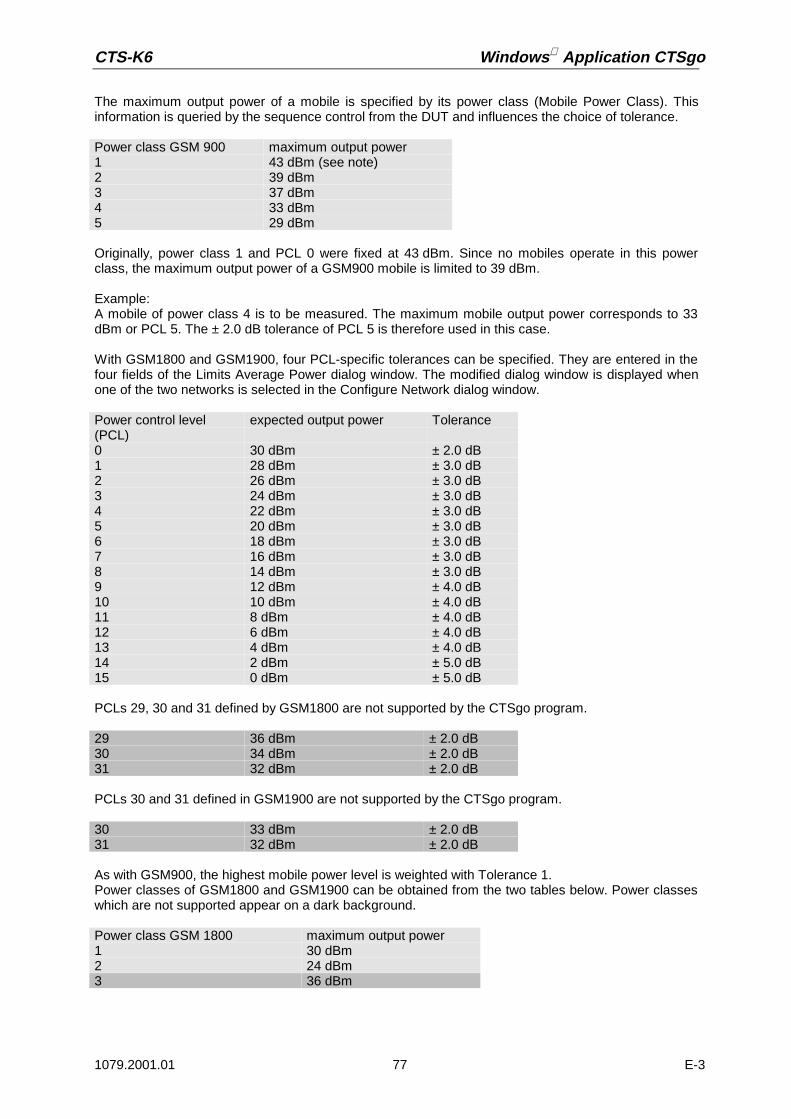
CTS-K6 Windows Application CTSgo
1079.2001.01 77 E-3
The maximum output power of a mobile is specified by its power class (Mobile Power Class). Thisinformation is queried by the sequence control from the DUT and influences the choice of tolerance.
Originally, power class 1 and PCL 0 were fixed at 43 dBm. Since no mobiles operate in this powerclass, the maximum output power of a GSM900 mobile is limited to 39 dBm.
Example:A mobile of power class 4 is to be measured. The maximum mobile output power corresponds to 33dBm or PCL 5. The ± 2.0 dB tolerance of PCL 5 is therefore used in this case.
With GSM1800 and GSM1900, four PCL-specific tolerances can be specified. They are entered in thefour fields of the Limits Average Power dialog window. The modified dialog window is displayed whenone of the two networks is selected in the Configure Network dialog window.
PCLs 29, 30 and 31 defined by GSM1800 are not supported by the CTSgo program.
PCLs 30 and 31 defined in GSM1900 are not supported by the CTSgo program.
As with GSM900, the highest mobile power level is weighted with Tolerance 1.Power classes of GSM1800 and GSM1900 can be obtained from the two tables below. Power classeswhich are not supported appear on a dark background.
Power class GSM 900 maximum output power1 43 dBm (see note)2 39 dBm3 37 dBm4 33 dBm5 29 dBm
Power control level(PCL)
expected output power Tolerance
0 30 dBm ± 2.0 dB1 28 dBm ± 3.0 dB2 26 dBm ± 3.0 dB3 24 dBm ± 3.0 dB4 22 dBm ± 3.0 dB5 20 dBm ± 3.0 dB6 18 dBm ± 3.0 dB7 16 dBm ± 3.0 dB8 14 dBm ± 3.0 dB9 12 dBm ± 4.0 dB10 10 dBm ± 4.0 dB11 8 dBm ± 4.0 dB12 6 dBm ± 4.0 dB13 4 dBm ± 4.0 dB14 2 dBm ± 5.0 dB15 0 dBm ± 5.0 dB
29 36 dBm ± 2.0 dB30 34 dBm ± 2.0 dB31 32 dBm ± 2.0 dB
30 33 dBm ± 2.0 dB31 32 dBm ± 2.0 dB
Power class GSM 1800 maximum output power1 30 dBm2 24 dBm3 36 dBm

Windows Application CTSgo CTS-K6
1079.2001.01 78 E-3
Entered values are set by pressing OK. If the entered limit values should not be set, terminate thedialog with Cancel.
Set limits are indicated in the second and third column of the measurement report. This can be seen inthe following extract from a measurement report.
Since power ramp tolerance evaluation is performed according to GSM specifications, the valuescannot be changed by CTSgo. The finding of CTS is transferred to the PC as a Passed or Failedmessage.
7.6.3 BER Measurements
This command opens the Limits BER dialog window where the tolerances for the bit error rate (BER)are set. BER measurements are receiver measurements in which bits from a random generator sentby the CTS are received by the mobile, demodulated and looped back at the RF. The CTS comparesthe received bit sequence with the sent one. The bit sequence is channel-coded to GSM, ie the bits areassigned to different classes.
Power class GSM 1900 maximum output power1 30 dBm2 24 dBm3 33 dBm
Fig.: Limits Average Power dialog window GSM1800/GSM1900
Fig.: Extract from measurement report: Average power / power ramp
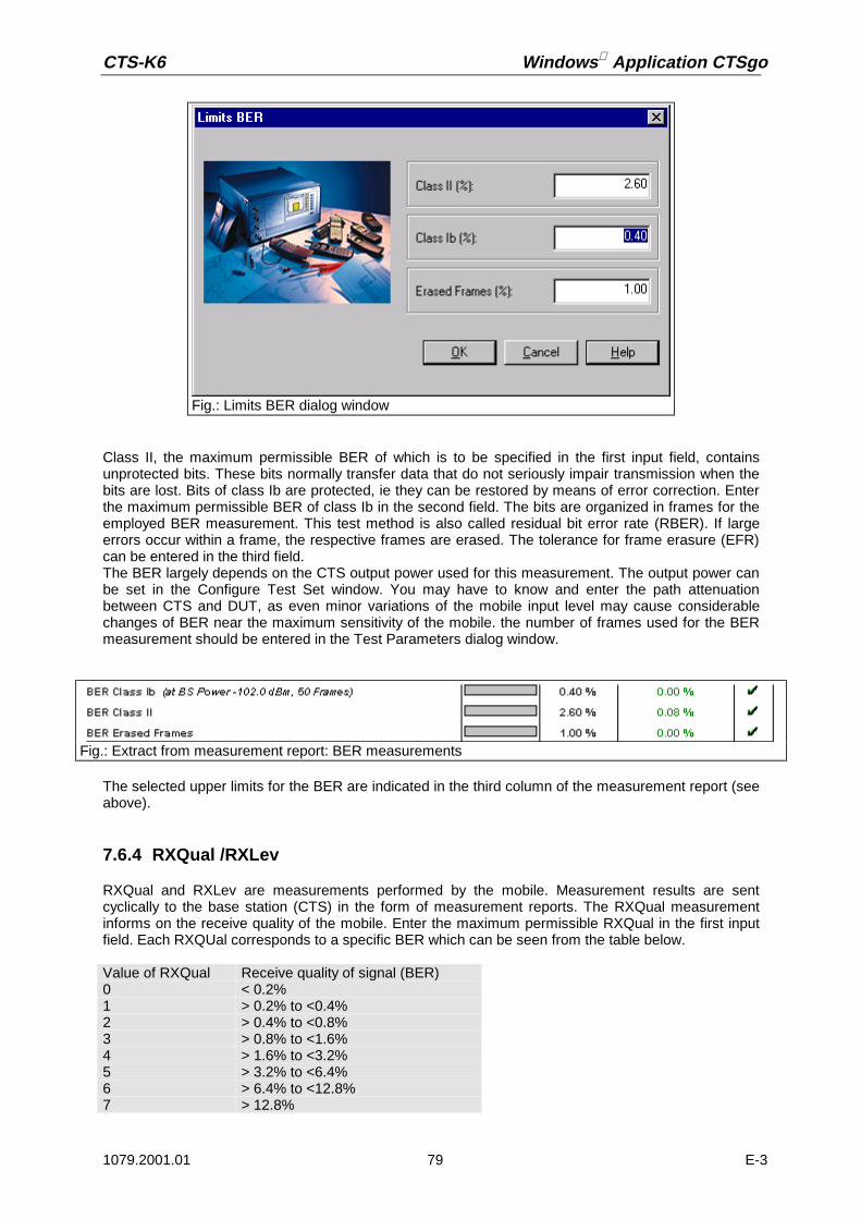
CTS-K6 Windows Application CTSgo
1079.2001.01 79 E-3
Class II, the maximum permissible BER of which is to be specified in the first input field, containsunprotected bits. These bits normally transfer data that do not seriously impair transmission when thebits are lost. Bits of class Ib are protected, ie they can be restored by means of error correction. Enterthe maximum permissible BER of class Ib in the second field. The bits are organized in frames for theemployed BER measurement. This test method is also called residual bit error rate (RBER). If largeerrors occur within a frame, the respective frames are erased. The tolerance for frame erasure (EFR)can be entered in the third field.The BER largely depends on the CTS output power used for this measurement. The output power canbe set in the Configure Test Set window. You may have to know and enter the path attenuationbetween CTS and DUT, as even minor variations of the mobile input level may cause considerablechanges of BER near the maximum sensitivity of the mobile. the number of frames used for the BERmeasurement should be entered in the Test Parameters dialog window.
The selected upper limits for the BER are indicated in the third column of the measurement report (seeabove).
7.6.4 RXQual /RXLev
RXQual and RXLev are measurements performed by the mobile. Measurement results are sentcyclically to the base station (CTS) in the form of measurement reports. The RXQual measurementinforms on the receive quality of the mobile. Enter the maximum permissible RXQual in the first inputfield. Each RXQUal corresponds to a specific BER which can be seen from the table below.
Fig.: Limits BER dialog window
Fig.: Extract from measurement report: BER measurements
Value of RXQual Receive quality of signal (BER)0 < 0.2%1 > 0.2% to <0.4%2 > 0.4% to <0.8%3 > 0.8% to <1.6%4 > 1.6% to <3.2%5 > 3.2% to <6.4%6 > 6.4% to <12.8%7 > 12.8%

Windows Application CTSgo CTS-K6
1079.2001.01 80 E-3
RXLev is the power received by the mobile and signaled to the base station as values from 0 to 63.
The RXLev test evaluates the deviation of RXLev from the RF output power of CTS specified in thetest set window. To give an example, a received RXLev value of 8 is interpreted as -102.5 dBm.Tolerances should not be too narrow because of the low resolution of this measurement.
To allow symmetrical tolerance evaluation, the base-station power for BER should be specified to 0.5dB. An example is given below:
BS power for BER: -89.5 dBmTolerance: 2.0 dBUpper tolerance limit: -87.5 dBm (RXLev =23)Lower tolerance limit: -91.5 dBm (RXLev =19)
Fig.: Limits RXQual / RXLev dialog window
RXLev value Signal strength (dBm)63 > -48 dBm62 -49 dBm to -48 dBm61 -50 dBm to -49 dBm... ...... ...2 -109 dBm to -108 dBm1 -110 dBm to -109 dBm0 below -110 dBm
Fig.: Extract from measurement report: RXQual / RXLev
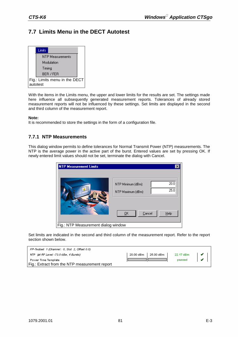
CTS-K6 Windows Application CTSgo
1079.2001.01 81 E-3
7.7 Limits Menu in the DECT Autotest
With the items in the Limits menu, the upper and lower limits for the results are set. The settings madehere influence all subsequently generated measurement reports. Tolerances of already storedmeasurement reports will not be influenced by these settings. Set limits are displayed in the secondand third column of the measurement report.
Note:It is recommended to store the settings in the form of a configuration file.
7.7.1 NTP Measurements
This dialog window permits to define tolerances for Normal Transmit Power (NTP) measurements. TheNTP is the average power in the active part of the burst. Entered values are set by pressing OK. Ifnewly entered limit values should not be set, terminate the dialog with Cancel.
Set limits are indicated in the second and third column of the measurement report. Refer to the reportsection shown below.
Fig.: Limits menu in the DECTautotest
Fig.: NTP Measurement dialog window
Fig.: Extract from the NTP measurement report

Windows Application CTSgo CTS-K6
1079.2001.01 82 E-3
7.7.2 Modulation
This dialog permits to define the tolerance limits for the B-field modulation, the frequency offset and thefrequency drift. Entered values are set by pressing OK. If newly entered limit values should not be set,terminate the dialog with Cancel.
Set limits are indicated in the second and third column of the measurement report. Refer to the reportsection shown below.
Notes:Data type Fig31 is always used for the CTSgo measurements. Within the B-field, this implies a numberof 0/1s bit sequences, then a number of set bits (1s bits), followed by a number of set bits (0s bits) anda final 0/1s bit sequence. On the average, this figure contains as many bits that are set as bits that arenot set in the B-field. If the arithmetic mean of the frequency offsets was generated, the result wouldcorrespond to the center frequency in the ideal case. The deviation is the frequency offset measured.Starting from this frequency offset, the maximum and the minimum deviation in the B-field will then bemeasured, with no differentiation being made between positive and negative deviation.The unit of the frequency drift can be entered in the respective box in kHz/slot. Otherwise, the outputwill be in kHz/ms.
Fig.: Limits Modulation dialog
Fig.: Extract from the Modulation measurement report

CTS-K6 Windows Application CTSgo
1079.2001.01 83 E-3
7.7.3 Timing
This dialog permits to define the tolerance limits for the jitter and timing measurements. The enteredvalues are set by pressing OK. If newly entered values should not be set, terminate the dialog withCancel.
Set limits are indicated in the second and third column of the measurement report. Refer to the reportsection shown below.
Note:Theoretically, the interval between two transmit bursts of a fixed part is ten milliseconds. Themeasured deviation from this ideal value constitutes the timing. To be able to perform thismeasurement correctly, it is necessary to average over several bursts. In parallel to the average-valuegeneration, the minimum and maximum time interval between two bursts is determined. The differencebetween minimum/maximum and average value is referred to as negative/positive jitter.
Fig.: Limits Timing dialog window
Fig.: Extract from the Timing measurement report

Windows Application CTSgo CTS-K6
1079.2001.01 84 E-3
7.7.4 BER / FER
This dialog permits to define the upper limit for the bit error rate (BER) and frame error rate (FER)measurements. Note that the entry is made in parts per million (ppm). The entered values are set bypressing OK. If the newly entered tolerance values should not be set, terminate the dialog with Cancel.
Set limits are indicated in the second and third column of the measurement report. Refer to the reportsection shown below.
Note:The bit error rate is measured in loop mode of the fixed part or portable part. Sent and received bitsare compared with each other. If more than 25% of the bits of a frame are faulty, this frame is declaredto be invalid. These invalid frames are taken into account in the Frame Error Rate and not in the BER.
Fig.: Limits BER / FER dialog window
Fig.: Extract from the BER / FER measurement report

CTS-K6 Windows Application CTSgo
1079.2001.01 85 E-3
7.8 Window Menu
The Windows menu is only active in the report display mode. In this window, the display can beadapted to your requirements. The current size of the display is indicated in the status bar.
7.8.1 Zoom 200%
This command expands the result display to 200% of the standard size.
7.8.2 Zoom 150%
This command expands the result display to 150% of the standard size.
7.8.3 Zoom 133%
This command expands the result display to 133% of the standard size.
7.8.4 Normal
With this command, the result window is displayed in its normal size (100%).
Fig.: Window menu
Popup menu Report display
Popup menu Report display
Popup menu Report display
Popup menu Report display

Windows Application CTSgo CTS-K6
1079.2001.01 86 E-3
7.8.5 Zoom 75%
This command reduces the result display to 75% of the standard size.
7.8.6 Zoom 66%
This command reduces the result display to 66% of the standard size.
7.8.7 Zoom 50%
This command reduces the result display to 50% of the standard size.
7.8.8 Zoom in
With this command, the size of the current result display is expanded by 10%.
7.8.9 Zoom out
With this command, the current result display is reduced by 10%.
7.9 Help Menu
7.9.1 Contents
This command calls the online help of CTSgo. You can obtain information on CTSgo by means of theonline help without having to refer to this manual. Information is provided in a Windows-typical formand available as a separate file in the program directory of CTSgo. The online help can be accessedwithout having to call CTSgo. Individual pages of the help information may be printed if required.
Popup menu Report display
Popup menu Report display
Popup menu Report display
Popup Menu Report display
Popup menu Report display
Fig.: Help menu

CTS-K6 Windows Application CTSgo
1079.2001.01 87 E-3
Fig.: CTSgo help window

Windows Application CTSgo CTS-K6
1079.2001.01 88 E-3
7.9.2 Using the Online Help
This command calls the online help of the employed operating system. The help is platform-specificand depends on the installation of the operating system. It also includes instructions on the use of thehelp files. General help topics of Windows can also be called.
7.9.3 Info About
This command opens a small dialog window where the current CTSgo version is displayed. Theplatform-specific version of the program is also indicated.
Fig.: Help topics of operating system
Fig.: Info about CTSgo dialog window

CTS-K6 Windows Application CTSgo
1079.2001.01 89 E-3
8 GSM Measurement Report
The measurement reports generated by the autotest provide a clear overview of measurement results.This section describes the layout of the measurement reports.
8.1 Header of Measurement Report
The header of the measurement report contains all static settings of the measurement, eg set inputand output attenuation, CTS output power during location update and the selected BCCH channel.Below this line are signaling parameters like the IMSI (International Mobile Subscriber Identity) of theSIM card used, the IMEI (International Mobile Equipment Identity) of the measured mobile, power classof the mobile and its revision level. The CTS identification is indicated in another line. Its purpose is tofacilitate the assignment of the measurement report to the instrument used. The configuration used forthe measurement is also indicated.
The header also contains general information such as date and time of completion of themeasurement, the operator’s name and a comment line. The top of the header shows the titleMeasurement Report and next to it at the right a logo. In contrast to all other information, these twoelements are also printed on the subsequent pages. The Rohde & Schwarz logo printed at the rightcan be replaced by another one. When items in the report are to be changed for furthermeasurements, select Report Settings in the Measurement menu.
Fig.: Report header

Windows Application CTSgo CTS-K6
1079.2001.01 90 E-3
8.2 Output of Measurement Information in the Report
When a call is set up by the mobile, the call number is entered in the measurement report. You canimplement a simple keyboard test.
The information on the individual measurements is indicated in five columns. The first columndescribes the measurement and, if required, certain measurement conditions, eg the number of burstsor frames or the CTS output power used.
Limits used for obtaining the decision Passed / Failed are indicated in the next two columns. A gray baris shown if there is no upper or lower limit for the measurement. For instance, setting a lower limit for aBER measurement would not make sense. The measured value is indicated in column four. Values forpassed tests are displayed in green and a hook appears in the last column. Red values indicate thatthe test failed and a red bar is displayed in column five. Tests not performed are displayed in blue incolumn four. This may happen when synchronization is lost during the measurement. Information onthe power control level (PCL) and employed channel or the associated test set are indicated in the firstcolumn instead of the modified parameters. This additional information is written in italics.
You can include a simple echo test in the measurement, the result of which is indicated below.
Fig.: Display of call number
Fig.: Output of measurement information in the report
Fig.: Display of echo test
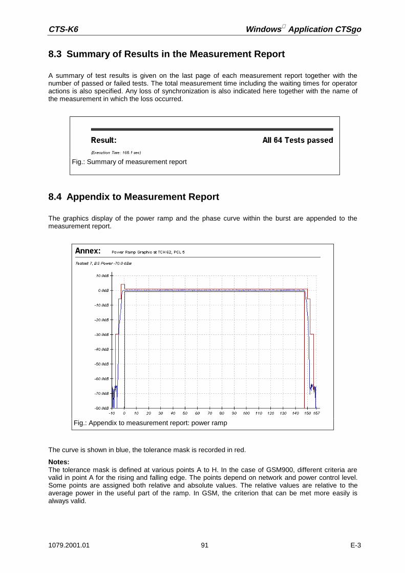
CTS-K6 Windows Application CTSgo
1079.2001.01 91 E-3
8.3 Summary of Results in the Measurement Report
A summary of test results is given on the last page of each measurement report together with thenumber of passed or failed tests. The total measurement time including the waiting times for operatoractions is also specified. Any loss of synchronization is also indicated here together with the name ofthe measurement in which the loss occurred.
8.4 Appendix to Measurement Report
The graphics display of the power ramp and the phase curve within the burst are appended to themeasurement report.
The curve is shown in blue, the tolerance mask is recorded in red.
Notes:The tolerance mask is defined at various points A to H. In the case of GSM900, different criteria arevalid in point A for the rising and falling edge. The points depend on network and power control level.Some points are assigned both relative and absolute values. The relative values are relative to theaverage power in the useful part of the ramp. In GSM, the criterion that can be met more easily isalways valid.
Fig.: Summary of measurement report
Fig.: Appendix to measurement report: power ramp

Windows Application CTSgo CTS-K6
1079.2001.01 92 E-3
The limit lines used by CTSgo in the display of the power time template can be obtained from thefollowing tables. According to GSM specifications, the reference point (0.0 µs) is positioned in themiddle of the bit length of bit 0. The evaluation of the tolerance mask is always performed by the CTSand not by CTSgo. The tolerance lines only serve for information.
Fig.: GSM Power Time Template

CTS-K6 Windows Application CTSgo
1079.2001.01 93 E-3
Point relative absoluteA1 -59.0 dB -36.0 dBmB -30.0 dB -17.0 dBmC -6.0 dBD 4.0 dBE 1.0 dBF -1.0 dBG -6.0 dBH -30.0 dB -17.0 dBmA2 -59.0 dB -54.0 dBmGSM 900 PCL 5-15
Point relative absoluteA1 -59.0 dB -36.0 dBmB -30.0 dB -17.0 dBmC -1.0 dBD 4.0 dBE 1.0 dBF -1.0 dBG -1.0 dBH -30.0 dB -17.0 dBmA2 -59.0 dB -54.0 dBmGSM 900 PCL 18 and 19
Point relative absoluteA1 -59.0 dB -36.0 dBmB -30.0 dB -17.0 dBmC -4.0 dBD 4.0 dBE 1.0 dBF -1.0 dBG -4.0 dBH -30.0 dB -17.0 dBmA2 -59.0 dB -54.0 dBmGSM 900 PCL 16
Point relative absoluteA1 -59.0 dB -36.0 dBmB -30.0 dB -17.0 dBmC -2.0 dBD 4.0 dBE 1.0 dBF -1.0 dBG -2.0 dBH -30.0 dB -17.0 dBmA2 -59.0 dB -54.0 dBmGSM 900 PCL 17
Point relative absoluteA1 -48.0 dB -48.0 dBmB -30.0 dB -20.0 dBmC -6.0 dBD 4.0 dBE 1.0 dBF -1.0 dBG -6.0 dBH -30.0 dB -20.0 dBmA2 -48.0 dB -48.0 dBmGSM 1800/1900 PCL 0-10
Point relative absoluteA1 -59.0 dB -36.0 dBmB -30.0 dB -17.0 dBmC -2.0 dBD 4.0 dBE 1.0 dBF -1.0 dBG -2.0 dBH -30.0 dB -17.0 dBmA2 -59.0 dB -54.0 dBmGSM 1800/1900 PCL 13 to 15
Point relative absoluteA1 -48.0 dB -48.0 dBmB -30.0 dB -20.0 dBmC -4.0 dBD 4.0 dBE 1.0 dBF -1.0 dBG -4.0 dBH -30.0 dB -20.0 dBmA2 -48.0 dB -48.0 dBmGSM 1800/1900 PCL 11
Point relative absoluteA1 -48.0 dB -48.0 dBmB -30.0 dB -20.0 dBmC -2.0 dBD 4.0 dBE 1.0 dBF -1.0 dBG -2.0 dBH -30.0 dB -20.0 dBmA2 -48.0 dB -48.0 dBmGSM 1800/1900 PCL 12
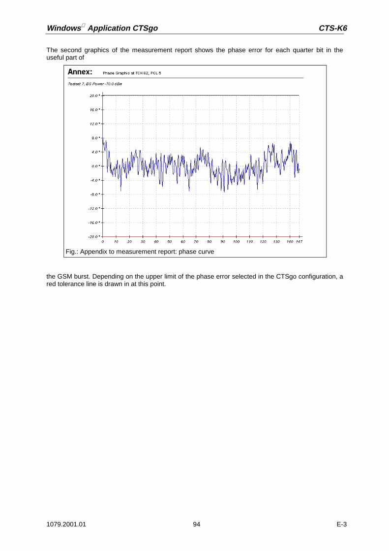
Windows Application CTSgo CTS-K6
1079.2001.01 94 E-3
The second graphics of the measurement report shows the phase error for each quarter bit in theuseful part of
the GSM burst. Depending on the upper limit of the phase error selected in the CTSgo configuration, ared tolerance line is drawn in at this point.
Fig.: Appendix to measurement report: phase curve
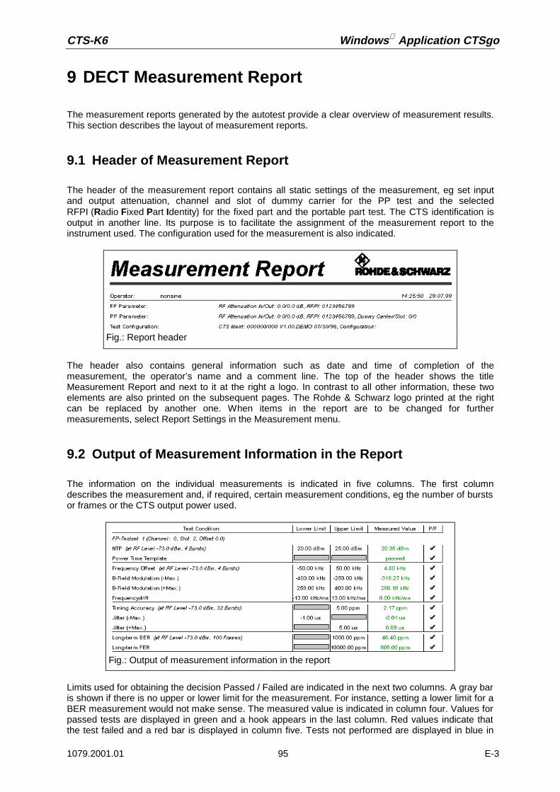
CTS-K6 Windows Application CTSgo
1079.2001.01 95 E-3
9 DECT Measurement Report
The measurement reports generated by the autotest provide a clear overview of measurement results.This section describes the layout of measurement reports.
9.1 Header of Measurement Report
The header of the measurement report contains all static settings of the measurement, eg set inputand output attenuation, channel and slot of dummy carrier for the PP test and the selectedRFPI (Radio Fixed Part Identity) for the fixed part and the portable part test. The CTS identification isoutput in another line. Its purpose is to facilitate the assignment of the measurement report to theinstrument used. The configuration used for the measurement is also indicated.
The header also contains general information such as date and time of completion of themeasurement, the operator’s name and a comment line. The top of the header shows the titleMeasurement Report and next to it at the right a logo. In contrast to all other information, these twoelements are also printed on the subsequent pages. The Rohde & Schwarz logo printed at the rightcan be replaced by another one. When items in the report are to be changed for furthermeasurements, select Report Settings in the Measurement menu.
9.2 Output of Measurement Information in the Report
The information on the individual measurements is indicated in five columns. The first columndescribes the measurement and, if required, certain measurement conditions, eg the number of burstsor frames or the CTS output power used.
Limits used for obtaining the decision Passed / Failed are indicated in the next two columns. A gray baris shown if there is no upper or lower limit for the measurement. For instance, setting a lower limit for aBER measurement would not make sense. The measured value is indicated in column four. Values forpassed tests are displayed in green and a hook appears in the last column. Red values indicate thatthe test failed and a red bar is displayed in column five. Tests not performed are displayed in blue in
Fig.: Report header
Fig.: Output of measurement information in the report

Windows Application CTSgo CTS-K6
1079.2001.01 96 E-3
column four. This may happen when synchronization is lost during the measurement. Information onused slot), employed channel and the channel offset or the associated test set are indicated in the firstcolumn instead of the modified parameters. This additional information is written in italics.
You can include a simple echo test in the measurement, the result of which is indicated below.
9.3 Summary of Measurements in the Measurement Report
A summary of test results is given on the last page of each measurement report together with thenumber of passed or failed tests. The total measurement time including the waiting times for operatoractions is also specified. Any loss of synchronization is also indicated here together with the name ofthe measurement in which the loss occurred.
9.4 Appendix to Measurement Report
Fig.: Output of echo test in the measurement report
Fig.: Summary of measurements in the measurement report
Fig.: Appendix to measurement report: power ramp

CTS-K6 Windows Application CTSgo
1079.2001.01 97 E-3
The graphics display of power ramp and modulation within the burst is appended to the measurementreport.
The curve display is shown in blue. The tolerance mask is recorded in red.
Note:The tolerance mask is defined at various points A to F.
The limit lines used by CTSgo in the display of the DECT power time template can be obtained fromthe following table.
The evaluation of the tolerance mask is always performed by CTS and not by CTSgo. The tolerancelines only serve for information.
DECT Power Time Template
Point relative absoluteA 20.0 nWB 25.0 uWC 4.0 dBD 1.0 dBE -1.0 dBF -6.0 dB

Windows Application CTSgo CTS-K6
1079.2001.01 98 E-3
The second graphics display of the measurement report shows the modulation within the burst. Themodulation used during the measurement is always Fig31. Recording starts at bit position -38. It canbe clearly seen that still no burst is being received by the tester. Then follows the sync field includingthe preamble for time synchronization between FP and PP. This field is followed by the A-field, whichdiffers from the surrounding fields in longer 0s and 1s sequences. The longest part is the B-field withthe long 1s and 0s bit sequence in its middle that is typical for Fig31. The burst is terminated by the X-field (CRC). The end of the burst is reached at bit position 424. However, recording only stops at bitposition 462.The frequency offset signaled by the CTS is displayed with a yellow line in the graphics. The tolerancefields for the B-field modulation are marked by two red lines.
Fig.: Appendix to measurement report: phase curve
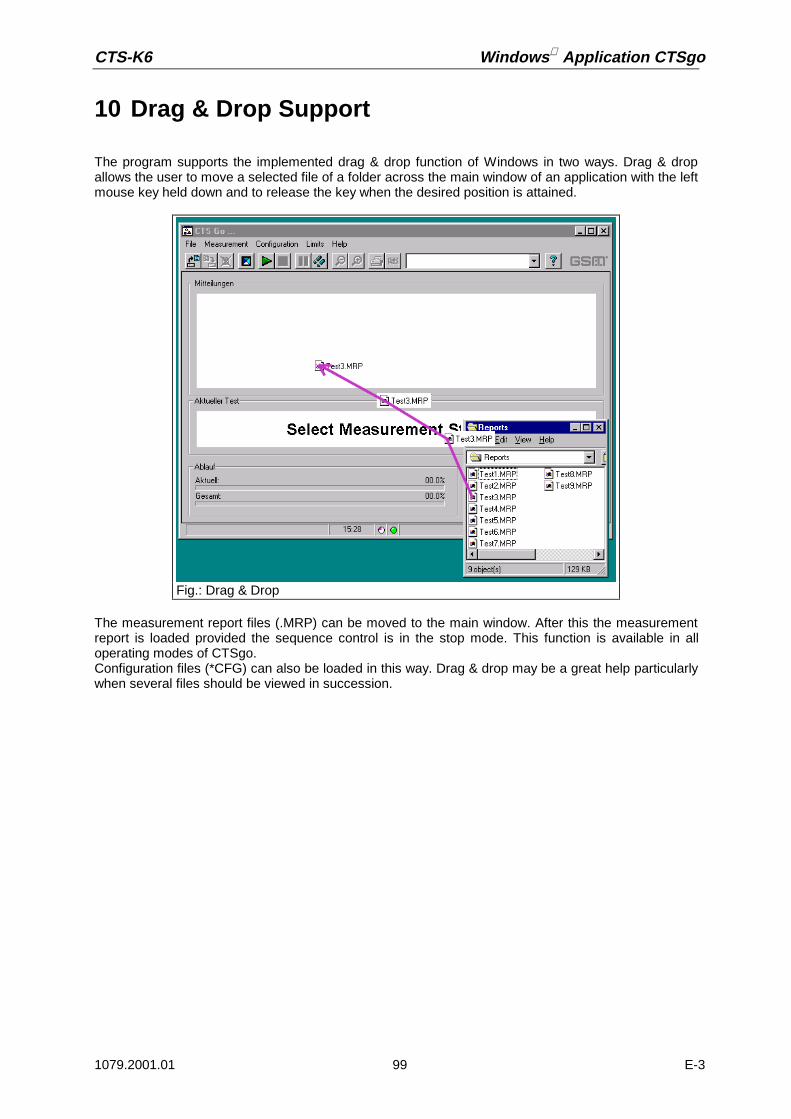
CTS-K6 Windows Application CTSgo
1079.2001.01 99 E-3
10 Drag & Drop Support
The program supports the implemented drag & drop function of Windows in two ways. Drag & dropallows the user to move a selected file of a folder across the main window of an application with the leftmouse key held down and to release the key when the desired position is attained.
The measurement report files (.MRP) can be moved to the main window. After this the measurementreport is loaded provided the sequence control is in the stop mode. This function is available in alloperating modes of CTSgo.Configuration files (*CFG) can also be loaded in this way. Drag & drop may be a great help particularlywhen several files should be viewed in succession.
Fig.: Drag & Drop

Windows Application CTSgo CTS-K6
1079.2001.01 100 E-3
11 Exchanging Measurement Report Data
CTSgo does not store country-specific information or texts in the measurement report files. If you haveperformed measurements with the English version of CTSgo and want to view the test results with theGerman version, window labeling as well as the information on date and time will be adapted to thedesired language.During the export of measurement results, the number format will be adapted to the country-specificstandard. The transfer of these files may cause problems when the data are imported to spreadsheetprograms, for instance. If data are to be transferred across country borders, it is advisable to send themeasurement report and export the data on the target platform.
Fig.: English and German report display

CTS-K6 Windows Application CTSgo
1079.2001.01 101 E-3
12 Examples of Application
The procedure for configuring the autotest will be explained with the aid of two examples. Readthrough these examples if you are still not at ease with the operation of CTSgo.
Before starting the examples, the following steps should be performed:
• Open the Configuration menu and select the Remote Port option. Enter remote-control parametersin the Remote Control Port (RS232) dialog window according to the settings in the CTS.
• Open the Measurement menu and select Report Settings. Enter your name and, if required, acomment in the Measurement Report Settings window. Activate the option “Display Report after theTests”. If necessary, change the logo displayed on the measurement reports.
12.1 Simple GSM Echo Test
During this measurement, a call should be set up and an echo test performed. The CTS should set upa call to the GSM-1800 mobile. The call should be cleared down by the user. The mobile is connectedto the CTS via an antenna coupler, the attenuation of the coupler is approx. 7 dB in both directions.
• Open the Configuration menu and select Network. Activate GSM1800 in the Configure Networkdialog window. Enter a power of –70 dBm for the location update. Close the window with OK.
• Select the Test Parameters command in the Configuration menu. The Configure Test Parametersdialog window is opened. Enter 512 for the BCCH. Enter 7.0 dB for input and output attenuationaccording to the settings of the antenna coupler. Close the dialog window with OK.
• Open the Select Tests dialog window by choosing Select Tests in the Configuration menu. CheckFirst Connection and Test Set 1. All other boxes should be empty. Confirm your settings with OK.
• Open the Configuration menu, select First Connect and activate Call from Base Station (CTS) in theConfigure First Connect dialog window. Confirm the settings with OK.
• Open the Configuration menu and select Test Set 1. Enter 62 for the TCH channel in the ConfigureTest Set 1 window. Activate 10 in the TCH Power Levels field. Enter –70.0 dBm for the StandardBS Power. Activate Echotest in the Measurements field. Close the dialog window with OK.
• Select First Disconnect in the Configuration menu and activate Release from Mobile in theConfigure First Disconnect dialog window. Confirm the settings with OK.
• Move your mouse to the center of the autotest window, press the righthand mouse key and hold itdown. With the key held down place the mouse cursor on Save Configuration in the popup menuand release the key. Enter a name, eg ECHOTEST.CFG in the Save Configuration dialog windowand select the directory for the file to be stored.
• Start the measurement by a click on the Start icon in the toolbar.

Windows Application CTSgo CTS-K6
1079.2001.01 102 E-3
12.2 Extended GSM Test
In our second example, and extended test of a GSM900 mobile is to be performed. After a first call hasbeen set up by CTS, all kind of GSM transmitter measurements are to be performed in channels 1, 62and 124 at the PCLs 5, 10 and 15. Statistical averaging over several bursts should not be performedand the CTS output level should be –70 dBm. With these measurements terminated, the call is to becleared down by the CTS. The second call should be set up by the user and an echo test performed onchannel 62. The CTS output level of –60 dBm should be reduced for the subsequent BERmeasurement over 50 frames. RXLev and RXQual of the mobile should also be checked. The callshould be released again by the user. The mobile is connected to the CTS by means of an RF cabletaken from a vehicle installation set; the cable loss is 0.5 dB.
• Open the Configuration menu and select Network. Activate GSM900 in the Configure Networkdialog window. enter a power of –70 dBm for the location update. Terminate the dialog with OK.
• Select the Test Parameters command in the Configuration menu. The Configure Test Parametersdialog window is opened. Enter 31 for the BCCH. Enter 0.5 dB for input and output attenuationaccording to the settings of the antenna coupler. Close the dialog window with OK.
• Open the Select Tests dialog window by choosing Select Tests in the Configuration menu. CheckFirst Connection, Test Set 1, Test Set 2, Test Set 3. All other boxes should be empty. Confirm yoursettings with OK.
• Open the Configuration menu, select First Connect and activate Call from Base Station (CTS) in theConfigure First Connect dialog window. Confirm the settings with OK.
• Open the Configuration menu and select Test Set 1. Enter 2 as TCH channel in the Configure TestSet 1 window. Activate the boxes “5“, “10“ and “15“ in the TCH Power Levels fields. Enter –70.0dBm for BS Power Standard. Check the boxes Frequency Error, Phase Error, Timing, AverageBurst Power and Power Ramp in the Measurements field. All other boxes in the Measurement fieldshould be empty. Close the dialog window by pressing OK.
• Repeat this step for Test Set 2 but enter 62 for the TCH channel.• The procedure for Test Set 3 is the same as described for test set 1 but enter TCH channel 124.• Select First Disconnect in the Configuration menu. Activate Release from Basestation (CTS) in the
Configure first Disconnect dialog window. Confirm the selection with OK.• Open the Configuration menu, select the Second Connect item and activate Call from Mobile in the
Configure second Connect dialog window. Confirm the settings with OK.• Open the Configuration menu and select Test Set 7. Enter 62 as TCH channel. Check box 10 in the
TCH Power Level field and enter –70.0 dBm for BS Power Standard. Enter –102.5 dBm for BSPOWER BER. Check BER class Ib, BER class II, BER EFR, RXQual, RXLev and Echotest in theMeasurement field. All other boxes of the Measurement field should be empty. Close the dialogwindow with OK.
• Select Second Disconnect in the Configuration menu and activate Release from Mobile in theConfigure second Connect dialog window. Confirm the settings with OK.
• Open the windows for the commands in the Limits menu one after the other; check and change thelimits for the individual measurements if you are not satisfied with the default values.

CTS-K6 Windows Application CTSgo
1079.2001.01 103 E-3
• Open the File menu and select Save Configuration. Enter a name, eg ENDTEST.CFG in the SaveConfiguration dialog window and select the directory where the file should be stored.
• Open the Measurement menu and click on Start.
12.3 DECT Test
In our third example, a DECT set consisting of a fixed part and a portable part is to be measured. TheRFPI of the set is not known. It is completely sufficient to check one channel in our measurement.Neither RF connectors nor an antenna coupler is available. Therefore, we cut off an RF cable where anN-type connector is connected at one end. There, we uncover about 4 centimeters of the innerconductor and strengthen it by soldering. This cable end is attached to the fixed part or portable part atthe place where the antenna is positioned using adhesive tape. We do not open the casing, since weonly want to get a rough idea about whether this set works or not. A measurement of the normaltransmit power in manual CTS mode resulted in an attenuation of approx. 10 dB at the portable partand approx. 12 dB at the fixed part.
• Open the Configuration menu and call PP Base settings, enter an input and output attenuation of 10dB each. 0 is entered for the carrier and slot of the dummy bearer. For the Q-packages we keep thedefault values of “000003FF0000“ for Q0, „003041108008“ for Q3, „006F0F000000“ for Q6 and„03060306“ for QMUX. Then terminate the dialog by pressing OK.
• Open the Configuration menu and call FP Base Settings. Enter an input and output attenuation of12 dB each. Check the boxes “Accept detected RFPI” and “Use detected RFPI in PP Test“. For thePMID we keep the default value of “EBE8D“. Enter 0 as antenna. Close the dialog window bypressing OK.
• Open the Configuration menu and the Select Tests dialog window. Activate the boxes FP Test, FPTest Set 1, PP Test and PP Test Set 1. All other boxes must be empty. Confirm your settings bymeans of OK.
• Open the Configuration menu and call FP Test Set 1. Enter the carrier 0, slot 2 and offset 0.0. Enteran RF Level of –70.0 dBm in the RX Measurements field. Select the BER and FER measurementusing the boxes. Enter 100 for the number of frames. Enter an RF Level of –65.0 dBm in the TXMeasurements field. The number of bursts for power and modulation measurements must be 4, thenumber of bursts in the timing measurement 32. Select all boxes of the TX Measurements fieldexcept Echotest. Close the dialog with OK.
• Open the Configuration menu and call PP Test Set 1. Enter carrier 0, slot 2 and offset 0.0. Enter anRF level of –70.0 dBm in the RX Measurements field. Select BER and FER measurement using theboxes. Enter 100 for the number of frames. Enter an RF level of –65.0 dBm in the TXMeasurements field. The number of bursts for power and modulation measurements should be 4,the number of bursts in the timing measurement 32. Select all boxes of the TX Measurements fieldexcept Echotest. Close the dialog window using OK.
• Call the commands of the Limits menu one after the other and vary the tolerance limits of theindividual measurements if you are not satisfied with the default values.
• Open the File menu and select Save Configuration. Enter a name, eg DECTTEST.CFG in the SaveConfiguration dialog window and select the directory where the file is to be stored.
• Open the Measurement menu and click on Start.

Windows Application CTSgo CTS-K6
1079.2001.01 104 E-3
13 Working with Different User Profiles
CTSgo allows for two different user profiles, the configurator and the operator profile. The operatormainly focuses on loading configurations and then starting the test. In order to prevent surroundingbase stations from disturbing the measurements, the operator can change the settings of the BCCHand TCH channels. In the DECT test, he can enter the RFPI. In the case of configurations starting withthe letters “UNIV“ he can as well change the attenuations, provided these configuration files are part ofthe current directory of CTSgo. In general, both the DECT and GSM parameters are stored or loadedsimultaneously in the case of configuration files.
13.1 The Configurator Profile
The configurator is entitled to overwrite all configurations, set tolerance limits and define the extent ofthe tests. When configuration files are loaded they are not checked for changes. If CTSgo is to beused by a configurator, the directory, where the executable CTS_GO.EXE file is stored, must alsocontain a valid file “CTS_GO.ULV“ .
13.2 The Operator Profile
The operator is only entitled to overwrite channel entries of the test sets, enter his name into themeasurement reports and determine the directory for automatic storage of the measurement reports.He is not entitled to set tolerance limits and define the extent of the tests. When configuration files areloaded, they are checked for modifications. If the contents of the configuration file does not correspondto the version defined by the configurator, the configuration file cannot be loaded and a warning isoutput on the screen. The input fields and the menu items that must not be changed are displayed asinactive. The operator profile is automatically set if the directory, where the executable CTS GO.EXEfile is stored, does not contain a valid “CTS_GO.EXE“ file.

CTS-K6 Windows Application CTSgo
1079.2001.01 105 E-3
14 Integrating Operator-specific Hints
When it is called up forthe first time, CTSgogenerates two furtherconfiguration files“CTS_GO.DS1“ and“CTS_GO.DS2“ . The file“CTS_GO.DS1“ refers tothe GSM autotest,“CTS_GO.DS2“ to theDECT autotest. Theseconfiguration files permitto integrate the output ofadditional information inthe test run. In general, adifferentiation is to bemade between popupwindows for text displayand popup windows forgraphics display. Thegraphics should not betoo large, a size of200x200 to 320x240pixels is recommended.The graphics should notbe overwritten in eachtest point, as this would
reduce the measurement rate. The graphics display remains active until a new entry is found in thesequence or the test run terminated. The input of an invalid file name is ignored. If the word HINT isentered under Filename, the output window will also be cleared. Normally, the entry “Animated“ isfollowed by 0. However, you can also create a bitmap with an animation consisting of four partialpictures. If you wish a partial picture size of 320x240 pixels, your file must have 1280x240 pixels. Thefirst partial picture displayed will then be loaded with an offset of 0 pixel and a width of 320 pixels, thesecond partial picture with an offset of 320 pixels and the same width, the third one with an offset of640 and the last partial picture with an offset of 960 pixels.
Fig.: Popup window with graphics loaded
Fig.: Animation sequence
Fig.:Single picture ofsequence

Windows Application CTSgo CTS-K6
1079.2001.01 106 E-3
14.1 The Section Everytime
This section contains 9 entries. The individual entries are displayed shortly after the start of theautotest in the order Text1/Filename1, Text2/Filename2 and Text3/Filename3. If several graphicsdisplays are to be shown one after the other, it is recommended to define the popup window for text aswell, since otherwise the second graphics, for instance, would immediately overwrite the first one. Onlythe popup windows of the text entry can stop the sequence control. These popup windows appeareach time the autotest has been started.
[Everytime]Text1 TextFilename1 Path to graphics file in BMP formatAnimated1 1 = Graphics animated, 0 = Graphics not animatedText2 TextFilename2 Path to graphics file in BMP formatAnimated2 1 = Graphics animated, 0 = Graphics not animatedText3 TextFilename3 Path to graphics file in BMP formatAnimated3 1 = Graphics animated, 0 = Graphics not animated
14.2 The Section Daily
This section contains 9 entries. The individual entries are displayed shortly after the start of theautotest in the order Text1/Filename1, Text2/Filename2 and Text3/Filename3. If several graphicsdisplays are to be indicated one after the other, it is recommended to define the popup window for textas well, since otherwise the second graphics, for instance, would immediately overwrite the first one.Only the popup windows of the test entry can stop the sequence control. These popup windows appearonly once a day after the start of the autotest; no further output will be made on this day.
[Daily]Text1 TextFilename1 Path to graphics file in BMP formatAnimated1 1 = Graphics animated, 0 = Graphics not animatedText2 TextFilename2 Path to graphics file in BMP formatAnimated2 1 = Graphics animated, 0 = Graphics not animatedText3 TextFilename3 Path to graphics file in BMP formatAnimated3 1 = Graphics animated, 0 = Graphics not animated

CTS-K6 Windows Application CTSgo
1079.2001.01 107 E-3
14.3 The Section Monthly
This section contains 9 entries. The individual entries are displayed shortly after the start of theautotest in the order Text1/Filename1, Text2/Filename2 and Text3/Filename3. If several graphicsdisplays are to be indicated one after the other, it is recommended to define the popup window for textas well, since otherwise the second graphics, for instance, would immediately overwrite the first one.Only the popup windows of the text entry can stop the sequence control. These popup windows appearonly once a month after the autotest has been started for the first time in this month; no further outputswill be made in this month.
[Monthly]Text1 TextFilename1 Path to graphics file in BMP formatAnimated1 1 = Graphics animated, 0 = Graphics not animatedText2 TextFilename2 Path to graphics file in BMP formatAnimated2 1 = Graphics animated, 0 = Graphics not animatedText3 TextFilename3 Path to graphics file in BMP formatAnimated3 1 = Graphics animated, 0 = Graphics not animated
14.4 The Section Topic
This section contains three entries. The entry „Description“ corresponds to the output in the output fieldof the autotest. This only serves for identification and cannot be overwritten. The graphics display in therespective popup window does not influence the sequence control. The graphics is displayed until anew entry is found in the sequence or the test run is terminated. If an invalid file name is entered, theoutput window will also be cleared.
[Topic00] etc.Description Name of single step in sequence controlFilename Path to graphics file in BMP formatAnimated 1 = Graphics animated, 0 = Graphics not animated
14.5 The Section TestsPassed
This section contains 2 entries. If all tests are passed, the respective graphics is displayed. It isrecommended not to combine this mode with the display mode “Display Report after the Tests“.
[TestsPassed]Filename Path to graphics file in BMP formatAnimated 1 = Graphics animated, 0 = Graphics not animated
14.6 The Section TestsFailed
This section contains 2 entries. If at least one test has failed, the respective graphics is displayed. It isrecommended not to combine this mode with the display mode “Display Report after the Tests“.
[TestsFailed]Filename Path to graphics file in BMP formatAnimated 1 = Graphics animated, 0 = Graphics not animated

Windows Application CTSgo CTS-K6
1079.2001.01 108 E-3
15 Adapting the Appearance of CTSgo
The user-defined graphics integration described before is also possible in a large display field of themain dialog instead of in a popup window. For this purpose, bit 15 must be set in the initialization file“CTS_GO.INI“ in the Application Settings section for Options.
[Application Settings]Options Bit 15 = 1 (corresponds to 08000hex)
Since the size of the main dialog can be varied, the ideal size of the graphics file cannot be specified ingreater detail. The graphics display is always increased or reduced to a size that fits exactly into theoutput window. The graphics should not be overwritten in each test point, as otherwise themeasurement rate would be reduced. The graphics display remains active until a new entry is found inthe sequence or the test run is terminated.If the dialog window is not increased, kindly use the values for the resolution 640x480 pixels.Approximate reference values can be obtained from the following table.
Screen size BMP Graphics640x480 pixels 496x139 pixels800x600 pixels 756x215 pixels1024x768 pixels 980x327 pixels

CTS-K6 Windows Application CTSgo
1079.2001.01 109 E-3
16 Problems, Questions and Solutions
16.1 Components Missing Signaled upon Program Startup
In addition to executable EXE files, the program contains runtime libraries (“DLLs“) which are loadedupon program start. These runtime libraries are first searched for in the specified current directory ofCTSgo and then, if required, in the Windows system directory. Check whether the files specified insection Software Components are available in your PC. If necessary, install the CTSgo softwareagain.
16.2 Serial Interface Cannot be Opened
The serial interface specified in your configuration is opened when CTSgo is started. This interfacemust not be used for other programs or the mouse.
16.3 CTS Cannot be Remote-Controlled
Compare settings of CTSgo and CTS. Check whether the employed cable meets the specifiedrequirements.
16.4 Program Signals Timeout
When setting the remote-control interface you can specify how long the CTSgo program is to wait for amessage from the CTS before it signals a timeout. with long measurements, eg a BER measurementwith a large number of frames, this waiting period may have to be extended.
16.5 Serial Data Transmission Impaired by Mouse Movements
Problems may occur when the serial mouse is connected for instance to COM1 and CTSgo operatedvia serial interface COM3. PCs often use the same hardware interrupt for COM1 and COM3 or COM2and COM4. Interactions between these two interfaces cannot be excluded in this case. Check theconstellation of your PC with the aid of the Windows system control. Refer to the Windows manual formore detailed information on the responsible device manager.
Abb.: Timeout warning
Windows Application CTSgo CTS-K6
1079.2001.01 110 E-3
16.6 Location Update Cannot be Performed
For a correct location update, the C0 carrier power received by the mobile must be sufficiently high.Increase the base-station power (CTS) for the location update in the Configure Network dialog. A testSIM card should be used in addition. Check also whether the mobile to be tested complies with thenetwork setting.
16.7 Synchronization Lost
The user-selected CTS output power may be too low and outside the sensitivity of your mobile.Increase the CTS output power for the respective test step. The output power is entered in theConfigure Test Set dialog window. It is also possible that the user-defined attenuation values are notcorrect.
16.8 Level Measurements Frequently out of Tolerance
The CTS considers the set attenuation in the level calculation. For this reason, the attenuation must beaccurately set.
16.9 Measurement Report Cannot be Loaded
The format of the selected measurement report is illegal. The file is either invalid or the report hasbeen saved with a previous version of CTSgo. In this case, the measurement report has to beconverted.
16.10 Drag & Drop not Working
Check that CTSgo is in the stop mode.
16.11 Program Cannot be Configured
Check that CTSgo is in the stop mode.
16.12 Generator Settings are not Immediately Performed
The CTSgo program requires a certain time period for settings in the module test. Observe theindication in the CTSgo status bar. A change from the “red lamp“ to the “green lamp“ indicates that thesettings are completed.

CTS-K6 Windows Application CTSgo
1079.2001.01 111 E-3
16.13 Can Several CTSs be Controlled from a PC ?
Several CTSs can be controlled from a PC if a sufficient number of free serial interfaces is available.To avoid interactions of the individual interfaces, a separate interrupt has to be used by each interface.With CTSgo a selection can only be made between the serial interfaces COM1 to COM4. Properfunctioning of the individual CTSgo sessions largely depends on the capacity of the PC used. Note thatduring each session the initialization file CTS_GO.INI in the current directory is overwritten. To avoidthis, CTSgo should be copied into several directories and these copies started only once.
16.14 Can CTSgo be Performed in the Background?
CTSgo can be performed in the background without problems. It may happen, however, that the otherprograms require so much computing power that serial data transmission is impaired.
16.15 Can Configuration Files be Read or Printed?
Configuration files have the format of Windows 3.x initialization files. Thus they can be read and ifnecessary printed. All configuration files are of identical format and available in English irrespective ofthe CTSgo version used. Each entry consists of a section designation in square brackets and entrieswith values after an equals sign. As is shown in the following example, the values can be directly read.
In the case of some entries, different options are determined by numerical entries.
Other entries are available in coded form. Such entries are described in the following. Individual entriesare OR-linked bit by bit and stored (eg 40hex + 80hex = C0hex).
[Test Set 1]
GSM 900 TCH Channel=62
[Application Settings] GSM Autotest GSM Module test DECT AutotestMode= 1 2 3
[Network] GSM 900 GSM 1800 GSM 1900Type= 1 2 3
[Connect 1] / [Connect 2] Call from mobile Call from base station (CTS)Type= 1 2
[Disconnect 1] / [Disconnect 2] Call release from mobile Call release from base station (CTS)Type= 1 2

Windows Application CTSgo CTS-K6
1079.2001.01 112 E-3
[Selected Tests] Key=First Connect 0001hex
Test Set 1 0002hex
Test Set 2 0004hex
Test Set 3 0008hex
Test Set 4 0010hex
Test Set 5 0020hex
Test Set 6 0040hex
Second Connect 0080hex
Test Set 7 0100hex
Test Set 8 0200hex
Test Set 9 0400hex
Test Set 10 0800hex
Test Set 11 1000hex
Test Set 12 2000hex
[Test Set x] Measurements=Frequency error 00001hex
Phase error 00002hex
Timing 00004hex
Average burst power 00008hex
Power ramp 00010hex
BER class Ib 00020hex
BER class II 00040hex
BER EFR 00080hex
RX Qual 00100hex
RX Lev 00200hex
Echo test 00400hex
Graphics Template 00800hex
Graphics Phase 01000hex
[Test Set x] TCH Power Levels =PCL 0 00001hex
PCL 1 00002hex
PCL 2 00004hex
PCL 3 00008hex
PCL 4 00010hex
PCL 5 00020hex
PCL 6 00040hex
PCL 7 00080hex
PCL 8 00100hex
PCL 9 00200hex
PCL 10 00400hex
PCL 11 00800hex
PCL 12 01000hex
PCL 13 02000hex
PCL 14 04000hex
PCL 15 08000hex
PCL 16 10000hex
PCL 17 20000hex
PCL 18 40000hex
PCL 19 80000hex

CTS-K6 Windows Application CTSgo
1079.2001.01 113 E-3
It is not recommended to change the values manually as in this case the CTSgo software may not runcorrectly.
16.16 Can Configuration Overwriting be Avoided?
Stored configuration files should be protected against overwriting. The best thing to do so is to write-protect these files in the operating system. To this end, open the Windows Explorer or the filemanager, click on the file and select Properties. Check the Read only box.
16.17 Can Default Values be Loaded?
Terminate CTSgo and delete the initialization file “CTS_GO.INI“. When the program is started again,default values will be loaded. Note that thus all values are reset, even your own settings.
[DECT Selected Tests] Key=FP Tests 0001hex
FP Test Set 1 0002hex
FP Test Set 2 0004hex
FP Test Set 3 0008hex
FP Test Set 4 0010hex
FP Test Set 5 0020hex
FP Test Set 6 0040hex
PP Tests 0080hex
PP Test Set 7 0100hex
PP Test Set 8 0200hex
PP Test Set 9 0400hex
PP Test Set 10 0800hex
PP Test Set 11 1000hex
PP Test Set 12 2000hex
[DECT Test Set x] Measurements=NTP 00001hex
Power ramp 00002hex
Graphics Template 00004hex
Frequency offset 00008hex
B-field Modulation 00010hex
Graphics Modulation 00020hex
Frequency drift 00040hex
Timing 00080hex
Jitter 00100hex
Echo test 00200hex
BER 00400hex
FER 00800hex
Windows Application CTSgo CTS-K6
1079.2001.01 114 E-3
17 Other Features
17.1 Debugging
CTSgo can prepare a protocol for all the data transferred via the serial interface. To activate thisfeatures, the command line for program call can be extended to “CTS_GO.EXE /SERPROT“.To this end, add “/SERPROT” to the entry in the Destination field of the link. When Windows 95 / 98 /NT is used, click on the program icon and select Properties via a popup menu using the right mousekey.
Note:Program icons of the start menu bar for Windows 95 / 98 / NT 4.0 are displayed when the Windowsdirectory is changed. Open the Profiles folder and then the Start Menu folder. Lower-level folders havethe same format as the Start menu bar. For more detailed information refer to the Windows manual.
As an alternative, Debug=1 can be entered in the [Remote] section of initialization file CTS_GO.INIwith the aid of an editor.
17.2 Demo Feature
CTSgo can simulate a measurement without a CTS being connected. Measured values are generatedin a random generator. To activate this feature, the command line for program call-up can be extendedto CTS_GO.EXE /DEMO.
As an alternative, Demo=1 can be entered in the [Remote] section of initialization file CTS_GO.INI.
17.3 Generate Code Feature
CTSgo can also save the command sequence to be sent to the CTS in the file GENERATE.IEE. To doso, Generate Code=1 can be entered in the [Remote] section of initialization file CTS_GO.INI with theaid of an editor.

CTS-K6 Windows Application CTSgo
1079.2001.01 115 E-3
18 Index
—A—absolute 91absolute path 43A-field 98Animated 105Animation 22Antenna 67Antenna coupler 47Application mode 40Arrow 17Attenuation 26, 56, 65Attenuation values 47automatic storage 43AUTOSAVE 43Autotest 20, 24Autotest dialog 20Average power 28, 76Averaging 62Averaging factor 30
—B—Bandwidth 62Bargraph 27Basic requirements 7Baud rate 54BCCH 22, 46, 89BDS52F.DLL 14BER 47, 70, 72, 84BER / FER 84BER Measurements 78B-field 98B-field modulation 70, 73, 82Bit modulation 26Bit sequences 82Bit timing 50Bit-error rate 47Bitmap 105Broadcast Channel 46Browse 10BS power 49BS power 110burst 56Burst 62, 91Burst analysis 26, 27, 29, 59Burst display 70, 73Burst power 50Bursts 73, 90, 95Buttons 18, 58
—C—C0 carrier 46C0 carrier 110Cable 8Call 49Call clear-down 52Call setup 49Car kit 47Carriage Return 40
Carrier 72Center frequency 82CFG 14Channel 27, 59, 62, 90, 96Channel entry 104Channel input 57, 59, 63Channel offset 96Channel spacing 59, 63Check boxes 18Checking the range 18Class Ib 50, 79Class II 50, 79Close 37Comment 42Components 14Computing power 111Configuration 89, 95Configuration file 22, 75, 81, 99Configuration files 104, 111Configurator 104Contents 86Continue 29Continuous 44Control block 24Conversion 57, 60, 63Copying 12country-specific 40, 100CRT-Z2 7CTS 8CTS Identification 89, 95CTS_GO.DS1 14, 105CTS_GO.DS2 14, 105CTS_GO.EXE 14CTS_GO.HLP 14CTS_GO.INI 14, 108, 111CTS_GO.ULV 14, 104CTS30 Parameter 54CTSgo functions 16current directory 43Current directory 111Current Test 21CW 62CW3230.DLL 14
—D—Daily 106Data bits 54Data exchange 100Data transmission 8Date 89, 95Debug Feature 114DECT autotest 34, 40DECT autotest dialog 20DECT measurement report 95DECT report display 20Deinstallation 14, 15Demo Feature 114Deviation 82Device manager 109Device status 22Display 7Display field 108

Windows Application CTSgo CTS-K6
1079.2001.01 116 E-3
Display mode 61DLL 109double-page display 39Drag & Drop 33, 99, 110Dummy Bearer 65, 66Dummy Carrier 95Dynamic range 59, 62
—E—Echo test 50, 70, 73, 90Echo Test 101EFR 50, 79E-GSM 50English 100Entering numerals 18Erased Frames 50, 79ETSI standard 65Everytime 106Examples of application 101Exit 41expected power 28Expected power 30Export 33, 40Extended Test 102, 103
—F—Failed 90, 95FER 70, 72, 84fictitious channel 63Fictitious channel 58, 60Fig31 82, 98File manager 113Filename 105Fixed Part 34, 65, 66, 68Floppy 9, 12Folder 11Format 43FP 34FP Base settings 66FP test set 68Frame 84Frames 70, 72, 79, 90, 95Freerun 59Freeze 29, 44Frequency 27Frequency drift 70, 73, 82Frequency error 28, 50, 75Frequency input 57, 59, 63Frequency offset 26, 27, 56, 57, 70, 73, 82, 98Frequency table 69, 72full size 16
—G—Generate Code Feature 114Generator mode 26Generator set 26Generator sets 27Generator settings 20, 56German 100Graphics 105Graphics file 43graphics result display 29Graphics result display 19green lamp 110
Green lamp 31GSM 1800 46GSM 1900 46GSM 900 46GSM autotest 40GSM Autotest 21GSM channel 57GSM frequency pattern 56GSM measurement report 89GSM module test 26, 40GSM report display 20, 33GSM specification 76GSM specifications 92GSM tolerance mask 29
—H—Handshake 8Hard disk memory 14Hard-disk storage 7Hardware interrupt 109Header 89, 95Header of measurement report 89, 95Height 43Help topics 88HF level 72HINT 105
—I—Icon 16Identification number 34IDLE 22IMEI 89IMSI 89Info about 88Information boxes 19Input attenuation 56, 60, 64Input boxes 18Input filter 62Installation components 14Interface 22, 111IQ spectrum 26, 30IQ Spectrum 62
—J—Jitter 70, 73, 83
—K—Keyboard test 90kHz/ms 82kHz/Slot 82
—L—left mouse key 99Level measurements 110Limit lines 97Load configuration 40Location Update 22, 46, 89Logo 43, 89, 95Loop mode 84Loss of synchronization 91, 96Lower limit 90, 95

CTS-K6 Windows Application CTSgo
1079.2001.01 117 E-3
—M—MAC identity 66MAC level 65Main dialog 108Main window 99Marker 31maximum output power 77MCE 22Measured value 90, 95Measurement range 27Measurement report 33, 99Measurement report settings 42Measurement time 48Menu „Configuration“ 46, 56, 65Menu „File“ 37Menu „Help“ 86Menu „Measurements“ 42Menu „Tolerance limits“ 75, 81Menu „window“ 85Menu bar 16Messages 21, 22Midamble 26, 56, 59MIDL 22Mobile Power Class 77Modulation 70, 73, 82, 98Module test dialog 20Monthly 107MRP 14MSYN 22
—N—Narrow spectrum 30Network 26, 27, 46, 58, 60, 64, 110Normal Transmit Power 81NTP 70, 73, 81NTP Measurement 81numeric result display 29Numerical measurement results 19
—O—Offset 69, 72OLE 33Online help 86, 88Open 37Operating system 88Operation 86operator 104Operator 42Option boxes 18options 47OR-linked bit by bit 111Output attenuation 56, 58Output boxes 19Output level 26, 70, 72, 73Output power 90, 95Oversampling 29, 30OWL52F.DLL 14
—P—Parameter set 56Parameter sets 22Parity 54Partial picture 105
Passed 90, 95Password 55Path 43Pause 44PCL 47, 76, 90, 91Peak 28, 50Peak phase error 75Peak power 28Peripherals 7Phase 30Phase / Frequency / Timing 75Phase curve 91Phase error 28, 50, 94Phase error curve 50Phase/frequency error measurement 47Pixel 105Pixels 108Platform 7Platforms 15platform-specific 88PMID 66Popup menu 17, 22, 27, 33, 36Popup menus 37Popup window 27, 29, 30, 105Portable Part 34, 65, 68Power class 77Power control level 47, 77Power ramp 29, 50, 70, 73, 91Power time template 92, 97Power trigger 59PP 34PP Base Settings 65PP test set 68Preamble 98Print 39Print preview 39Print setup 39Processor 7Program icon 11Program menus 37Program start 109Progress bar 22Progress bars 21Progress Bars 19Protocol 54Protocol RTS/CTS 8Pulldown menu 16
—Q—Q0 65Q3 65Q6 65QMUX 65Q-packages 65Quarter bits 29
—R—RAM 7Ramp 56Range markers 19Receive quality of signal 79red lamp 110Red lamp 31Reference level 31Reference point 92
Windows Application CTSgo CTS-K6
1079.2001.01 118 E-3
relative 91relative path 43Remote-control interface 54Report display 33Residual bit error rate 79Resolution 7, 108Result display 27Results 21RF In/Out 26, 56RF level 70, 73RF Out 2 26, 56RF output power 49RFPI 34, 65, 66, 95righthand mouse key 17, 22RMS 28, 50RMS phase error 75RS232 54RTS 8RXLev 47, 50, 79RXQual 50, 79
—S—Sa 38SAMPLE.MRP 14Save as 38Save configuration 41Scrollbars 17Section designation 111Select tests 48, 68Sequence control 21, 22, 24, 31Set only 26Setting up a call 23Setup 9Short name 58, 60, 64SIM card 7, 46, 89single-page display 39Single-step command 24Slider 17, 19Slot 69, 72, 95, 96Software Components 109Software version 7Spreadsheet program 40Start 44Start command 24Status bar 21, 110Status Bar 17Status check 22Status indication of sequence control 22Status information on CTS operating status 22Step 44Stop 44Stop bits 54Stop command 24Stop mode 21, 24, 27, 31, 33, 110Structure 25, 33, 35subdirectory 43Summary 91, 96Sync field 98Synchronization 22, 59, 90, 96, 110System control 15, 109
—T—Tabulated form 40Target directory 10TCH 47, 49Template 70, 73Terminator 54Test 24Test Parameter 47Test SIM 110TestsFailed 107TestsPassed 107Text display 105Time 21, 89, 95Time accuracy 70Timeout 22, 109Timing 83Timing error 75Title bar 16To and fro movement 22Tolerance limits 75, 81, 104Tolerance lines 29Tolerance mask 29, 91, 97Tolerances 76Toolbar 17Topic 107Total measurement time 91, 96Traffic Bearer 69, 72Traffic channel 47Training sequence 26, 27, 59Transmitter and receiver tests 22Trigger mode 27, 59
—U—unprotected bits 79Upper limit 90, 95Useful Part 91, 94User profiles 104User-defined bitmap 43
—W—Wait mode 24Width 43Windows 95 / 98 / NT4.0 9Windows application 40Windows directory 14Windows Explorer 113Windows manual 39, 109Windows manual 114Windows system 22Windows system directory 109Windows system directory 14Write protection 113
—Z—Zoom 85, 86
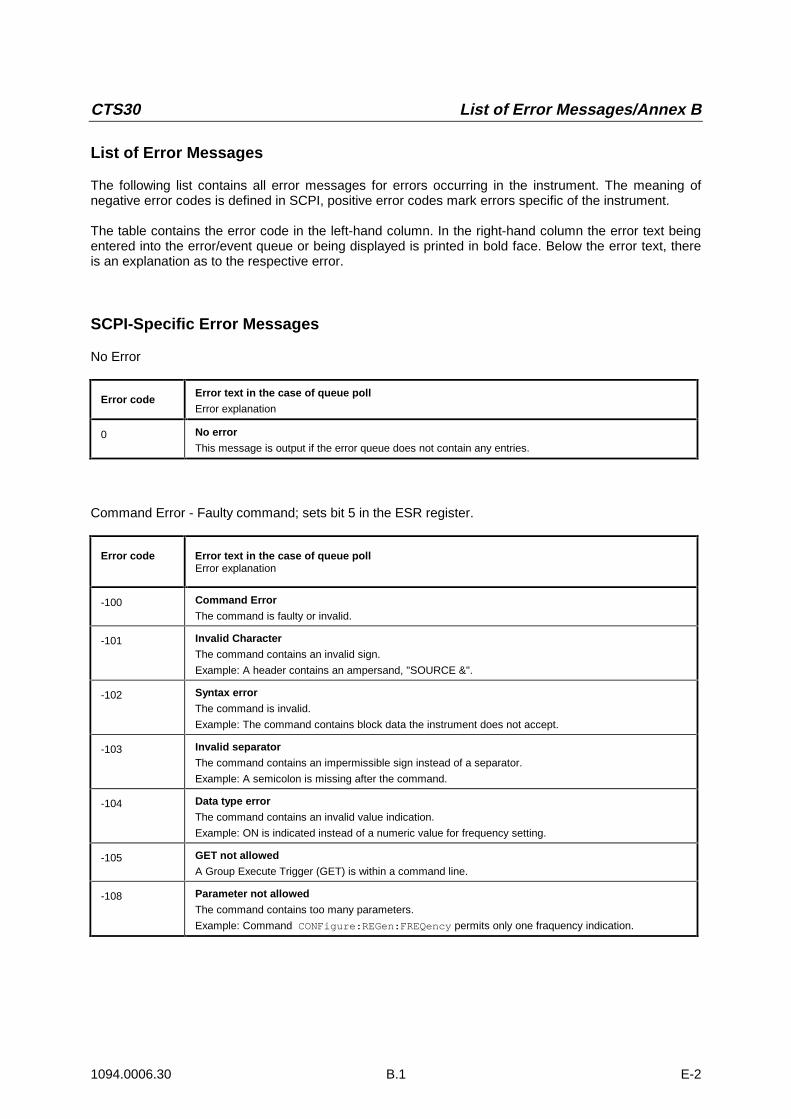
CTS30 List of Error Messages/Annex B
1094.0006.30 B.1 E-2
List of Error Messages
The following list contains all error messages for errors occurring in the instrument. The meaning ofnegative error codes is defined in SCPI, positive error codes mark errors specific of the instrument.
The table contains the error code in the left-hand column. In the right-hand column the error text beingentered into the error/event queue or being displayed is printed in bold face. Below the error text, thereis an explanation as to the respective error.
SCPI-Specific Error Messages
No Error
Error codeError text in the case of queue poll
Error explanation
0 No error
This message is output if the error queue does not contain any entries.
Command Error - Faulty command; sets bit 5 in the ESR register.
Error code Error text in the case of queue pollError explanation
-100 Command Error
The command is faulty or invalid.
-101 Invalid Character
The command contains an invalid sign.
Example: A header contains an ampersand, "SOURCE &".
-102 Syntax error
The command is invalid.
Example: The command contains block data the instrument does not accept.
-103 Invalid separator
The command contains an impermissible sign instead of a separator.
Example: A semicolon is missing after the command.
-104 Data type error
The command contains an invalid value indication.
Example: ON is indicated instead of a numeric value for frequency setting.
-105 GET not allowed
A Group Execute Trigger (GET) is within a command line.
-108 Parameter not allowed
The command contains too many parameters.
Example: Command CONFigure:REGen:FREQency permits only one fraquency indication.
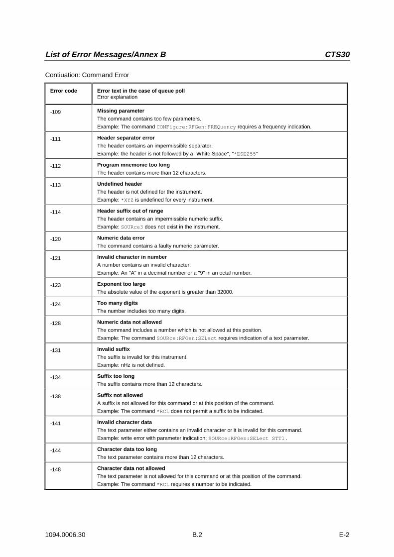
List of Error Messages/Annex B CTS30
1094.0006.30 B.2 E-2
Contiuation: Command Error
Error code Error text in the case of queue pollError explanation
-109 Missing parameter
The command contains too few parameters.
Example: The command CONFigure:RFGen:FREQuency requires a frequency indication.
-111 Header separator error
The header contains an impermissible separator.
Example: the header is not followed by a "White Space", "*ESE255"
-112 Program mnemonic too long
The header contains more than 12 characters.
-113 Undefined header
The header is not defined for the instrument.
Example: *XYZ is undefined for every instrument.
-114 Header suffix out of range
The header contains an impermissible numeric suffix.
Example: SOURce3 does not exist in the instrument.
-120 Numeric data error
The command contains a faulty numeric parameter.
-121 Invalid character in number
A number contains an invalid character.
Example: An "A" in a decimal number or a "9" in an octal number.
-123 Exponent too large
The absolute value of the exponent is greater than 32000.
-124 Too many digits
The number includes too many digits.
-128 Numeric data not allowed
The command includes a number which is not allowed at this position.
Example: The command SOURce:RFGen:SELect requires indication of a text parameter.
-131 Invalid suffix
The suffix is invalid for this instrument.
Example: nHz is not defined.
-134 Suffix too long
The suffix contains more than 12 characters.
-138 Suffix not allowed
A suffix is not allowed for this command or at this position of the command.
Example: The command *RCL does not permit a suffix to be indicated.
-141 Invalid character data
The text parameter either contains an invalid character or it is invalid for this command.
Example: write error with parameter indication; SOURce:RFGen:SELect STT1.
-144 Character data too long
The text parameter contains more than 12 characters.
-148 Character data not allowed
The text parameter is not allowed for this command or at this position of the command.
Example: The command *RCL requires a number to be indicated.

CTS30 List of Error Messages/Annex B
1094.0006.30 B.3 E-2
Continuation: Command Error
Error code Error text in the case of queue pollError explanation
-151 Invalid string data
The command contains a faulty string.
Example:An END message has been received prior to the terminating apostrophe.
-158 String data not allowed
The command contains a valid string at a position which is not allowed.
Example: A text parameter is set in quotation marks, SOURce:RFGen:SELect "SETting1"
-161 Invalid block data
The command contains faulty block data.
Example: An END message was received prior to reception of the expected number of data.
-168 Block data not allowed
The command contains valid block data at an impermissible position.
Example:
-171 Invalid expression
The command contains an invalid mathematical expression.
Example: the expression contains mismatching parentheses.
-178 Expression data not allowed
The command contains a mathematical expression at an impermissible position.
Example:
-180 Macro errorA faulty macro has been defined, or an error has occurred during execution of a macro.
Execution Error - Error on execution of a command; sets bit 4 in the ESR register
Error code Error text in the case of queue pollError explanation
-200 Execution error
Error on execution of the command.
-221 Settings conflict
There is a conflict between setting of parameter value and instrument state.
Example: External attenuation has been set in a state other than IDLE.
-222 Data out of range
The parameter value lies out of the permissible range of the instrument.
Eample: The command *RCL only permits entries in the range from 0 to 50.
-223 Too much data
The command contains too many data.
Example: The instrument does not have sufficient storage space.
-241 Hardware missing
The command cannot be executed due to missing hardware.
Example: An option is not fitted.

List of Error Messages/Annex B CTS30
1094.0006.30 B.4 E-2
Device Specific Error; sets bit 3 in the ESR register
Error code Error test in the case of queue pollError explanation
-300 Device-specific error
SM3-specific error not defined in greater detail.
-350 Queue overflowThis error code is entered in the queue instead of the actual error code if the queue is full. It indicatesthat an error has occurred but not been accepted. The queue can accept 5 entries.
Query Error - Error in data request; sets bit 2 in the ESR register
Error code Error text in the case of queue pollError explanation
-400 Query error
General error occurring when data are requested by a query.
-410 Query INTERRUPTED
The query has been interrupted.
Example: After a query, the instrument receives new data before the response has been sent completely.
-420 Query UNTERMINATED
The query is incomplete.
Example: The instrument is addressed as a talker and receives incomplete data.
-430 Query DEADLOCKED
The query cannot be processed.
Example: The input and output buffers are full, the instrument cannot continue operation.
-440 Query UNTERMINATED after indefinite response
A query is in the same command line after a query which requests an indefinite response.

CTS30 List of Commands/Annex C
1094.0006.30 C.1 E-4
1 List of Commands / Remote Control
1.1 General Information
1.1.1 States
In the description of the commands, the following abbreviations are used for indication of the permissible states: IDLE: ..Initial state of the CTS; is also achieved by means of PROCedure:SELect[:TEST] NONE. MIDL: MS test selected (BCCH is generated) MSYN: MS test: Synchronised (Location update is finished) MCE: MS test: Call established MOD: Module test in idle state IQSP: IQ-spectrum active RFG: RF generator active BAN: Burst Analysis active ALL: All states (IDLE, MIDL, MSYN, MCE, MOD, IQSP, BAN, or RFG) The following diagram explains the individual transitions of states:
IDLE
MIDL MOD
RFG
IQSP BANMSYN
MCE
PROC:SEL MANUAL PROC:SEL MODIDLE
LOCATION UPDATE
PROC:SEL RFG PROC:SEL RFGCALL TO OR
FROM MOBILE
PROC:SEL NONE
PROC:SEL NONE
PROC:SEL IQSPECPROC:SEL BANALYSIS
PROC:SEL MODIDLE
PROC:SEL IQSPECPROC:SEL BANALYSIS
PROC:SEL MODIDLE
List of Commands/Annex C CTS30
1094.0006.30 C.2 E-4
1.1.2 DCS1800 (GSM1800)
If DCS1800 is the desired network type, the switch over must be made by means of CONFigure:NETWork DCS1800 before changing the configuration set-up. After the switch over, all commands act on the DCS1800 data set, without switch over the GSM data set is used.
1.1.3 DCS1900 (GSM1900)
If DCS1900 is the desired network type, switchover using CONFigure:NETWork DCS1900 must be made prior to changing the configuration set-up.
1.1.4 GSM850 (GSM850)
If GSM850 is the desired network type, switchover using CONFigure:NETWork GSM850 must be made prior to changing the configuration set-up.
1.1.5 Note
<numeric_value> denotes a numeric value; MAXimum or MINimum can be indicated as well unless stated otherwise. If <numeric_value> may contain a unit, indicating the unit is optional. The value is always returned without a unit. Some commands allow ON and OFF instead of a value (for activating or deactivating the associated parameter). Specification of a value (numeric_value) implies a transition to ON. If OFF is set at the time of a query, OFF will be returned instead of the value. <value> denotes a character from a list; only list entries are permissible. All commands are structured analogously to the SCPI description, i.e. the upper-case letters indicate the short form of the command; the CTS only accepts this short form as an abbreviation (according to SCPI), otherwise the long form is to be used. Commands encapulated in square brackets, [:COMMand ], are optional words that do not have to be included.
1.1.6 Error Recovery
If no value is existing with queries or the value is invalid, NAN is returned instead of the value. An overflow of the value is indicated by INF, a missing input signal by means of NINF. If the CTS is not in the right state to be able to carry out the command, SCPI error -221, "Settings conflict" is generated. No value is returned in the case of queries. The permissible state is indicated in the following table in the column "state". If, however, an option to execute a command is missing, SCPI error -241, "Hardware missing" is displayed. No result is returned either in the case of a query. The option necessary to execute the command is entered in the tables under "option".
1.1.7 RESET Values
Unless otherwise specified, the values given in the column "Default:", are the factory default values of the CTS.

CTS30 List of Commands/Annex C
1094.0006.30 C.3 E-4
1.2 Settings
1.2.1 Input and Output
External attenuation at the output RF In/Out
Syntax: GSM850: source:correction:loss:low:agsm <value> source:correction:loss:mid:agsm <value> source:correction:loss:high:agsm <value> GSM900: source:correction:loss:low:gsm <value> source:correction:loss:mid:gsm <value> source:correction:loss:high:gsm <value> GSM1800: source:correction:loss:low:pcn <value> source:correction:loss:mid:pcn <value> source:correction:loss:high:pcn <value> GSM1900: source:correction:loss:low:pcs <value> source:correction:loss:mid:pcs <value> source:correction:loss:high:pcs <value>
Arfcn Range: 128 – 169 170 – 210 211 – 251 975 - 1023 and 0 – 30 31 – 78 79 – 124 512 – 635 636 – 759 760 – 885 512 – 611 612 – 711 712 – 810
Value range: GSM850/GSM900 / GSM1800 / GSM1900: 0.0 … +30.0 (unit: dB)
Default: 0.0 dB
State: Set: IDLE Query: ALL
Option: none
With Query Note: Positive values refer to an attenuation, (N1)
External attenuation at the input RF In/Out
Syntax: GSM850: source:correction:loss:low:agsm <value> source:correction:loss:mid:agsm <value> source:correction:loss:high:agsm <value> GSM900 sense:correction:loss:low:gsm <value> sense:correction:loss:mid:gsm <value> sense:correction:loss:high:gsm <value GSM1800: sense:correction:loss:low:pcn <value> sense:correction:loss:mid:pcn <value> sense:correction:loss:high:pcn <value> GSM1900: sense:correction:loss:low:pcs <value> sense:correction:loss:mid:pcs <value> sense:correction:loss:high:pcs <value>
Arfcn Range: 128 – 169 170 – 210 211 – 251 975 - 1023 and 0 – 30 31 – 78 79 – 124 512 – 635 636 – 759 760 – 885 512 – 611 612 – 711 712 – 810
Value range: GSM850/GSM900 / GSM1800 / GSM1900: 0.0 … +30.0 (unit: dB)
Default: 0.0 dB
State: Set: IDLE Query: ALL
Option: none
With Query Note: Positive values refer to an attenuation, (N1)

List of Commands/Annex C CTS30
1094.0006.30 C.4 E-4
External attenuation at RF Out 2
Syntax: source2:correction:loss:magnitude <value>
Value range: GSM850/GSM900 / GSM1800 / GSM1900: 0.0 … +30.0 (unit dB)
Default: 0.0 dB
State: Set: IDLE Query: ALL
Option: B7
With Query Note: Positive values refer to an attenuation, (N1)
Coupler Usage
Syntax: SOURce:CORRection:LOSS:COUPler <value>
Value range: OFF ON
Default: OFF
State: IDLE Option: none With Query Entered attenuations have no influence in position OFF.

CTS30 List of Commands/Annex C
1094.0006.30 C.5 E-4
1.2.2 Signalling and RF Parameters
1.2.2.1 Signalling Parameters of the Mobile Station
International Mobile Subscriber Identity (IMSI)
Syntax: SENSe:SIGNalling:IDENtity:IMSI?
Return: <string> (max. 15 characters)
State: MSYN, MCE Option: none Query only Note: (N2)
International Mobile Equipment Identity (IMEI)
Syntax: SENSe:SIGNalling:IDENtity:IMEI?
Return: <string> (max. 15 characters)
State: MSYN, MCE Option: none Query only Note: (N2)
Revision level of mobile
Syntax: SENSe:SIGNalling:IDENtity:MS:REVision:LEVel?
Return: PH1 PH2
State: MSYN, MCE Option: none Query only
Receiving level at Mobile Station (RXLEV)
Syntax: SENSe:SIGNalling:RXLev?
Return: 0 ... 63
State: MCE Option: none Query only Note: (N2)
Quality of Reception at Mobile Station (RXQUAL)
Syntax: SENSe:SIGNalling:RXQual?
Return: 0 ... 7
State: MCE Option: none Query only Note: (N2)

List of Commands/Annex C CTS30
1094.0006.30 C.6 E-4
Dialled number
Syntax: SENSe:SIGNalling:DNUMber?
Return: <string> (max. 20 digits) or “- - -“
State: MCE Option: none Query only Note: (N2)
Frequency Band
Syntax: SENSe:SIGNalling:FREQuency:BAND:CURRent? SENSe:SIGNalling:FREQuency:BAND:SECOnd?
Return: P-GSM900 (arfcn: 0 - 124) E-GSM900 (arfcn: 975 - 1023) R-GSM900 (arfcn: 955-974) GSM1800 (arfcn: 512 - 885) GSM1900 (arfcn: 512 - 810) GSM850 (arfcn: 128 - 251) Invalid - No frequency information on second network available (only GSM900/GSM1800 mobiles provide frequency information).
Default: DUM
State: MSYN, MCE
Option: none
Query only Note: Current: Frequency information on current network
Power Class
Syntax: SENSe:SIGNalling:POWEr:CLASs:CURRent? SENSe:SIGNalling:POWEr:CLASs:SECOnd?
Return: GSM850: 1… 5 GSM: 1… 5 GSM1800: 1… 2 GSM1900: 1… 2
State: MSYN, MCE
Option: none
Query only Note: Current: Power Class information on current network Second: Power Class information on a second network
Measured power of mobile (peak value)
SENSe:POWer:MS? is used to measure the transmitter power of the mobile. SENSe:SIGNalling:POWer:LEVel? indicates the nominal value.
Syntax: SENSe:POWer:MS?
Return: RF In Out: (0.0 + ext. att.) ... (+39 + ext. att.) (unit: Dbm)
State: MCE Option: none Query only

CTS30 List of Commands/Annex C
1094.0006.30 C.7 E-4
1.2.2.2 Signalling Parameters for CTS
Mobile Country Code
Syntax: CONFigure:SIGNalling:IDENtity:MCC <numeric_value>
Value range: GSM 0 ... 999 GSM850 0 ... 999 DCS1800: 0 ... 999 DCS1900: 0 ... 999
Default: 1
State: Set: IDLE Query: ALL
Option: none With Query
Mobile Network Code
Syntax: CONFigure:SIGNalling:IDENtity:MNC <numeric_value>
Value range: GSM 0 ... 99 GSM850 0 ... 999 DCS1800: 0 ... 99 DCS1900: 0 ... 999
Default: 1
State: Set: IDLE Query: ALL
Option: none With Query
Network Colour Code
Syntax: CONFigure:SIGNalling:IDENtity:NCC <numeric_value>
Value range: GSM 0 ... 7 GSM850 0 ... 7 DCS1800: 0 ... 7 DCS1900: 0 ... 7
Default: 0
State: Set: IDLE Query: ALL
Option: none With Query
Location Area Code
Syntax: CONFigure:SIGNalling:IDENtity:LAC <numeric_value>
Value range: GSM 0 ... 7 GSM850 0 ... 7 DCS1800: 0 ... 65535 DCS1900: 0 ... 65535
Default: 1
State: Set: IDLE Query: ALL
Option: none With Query
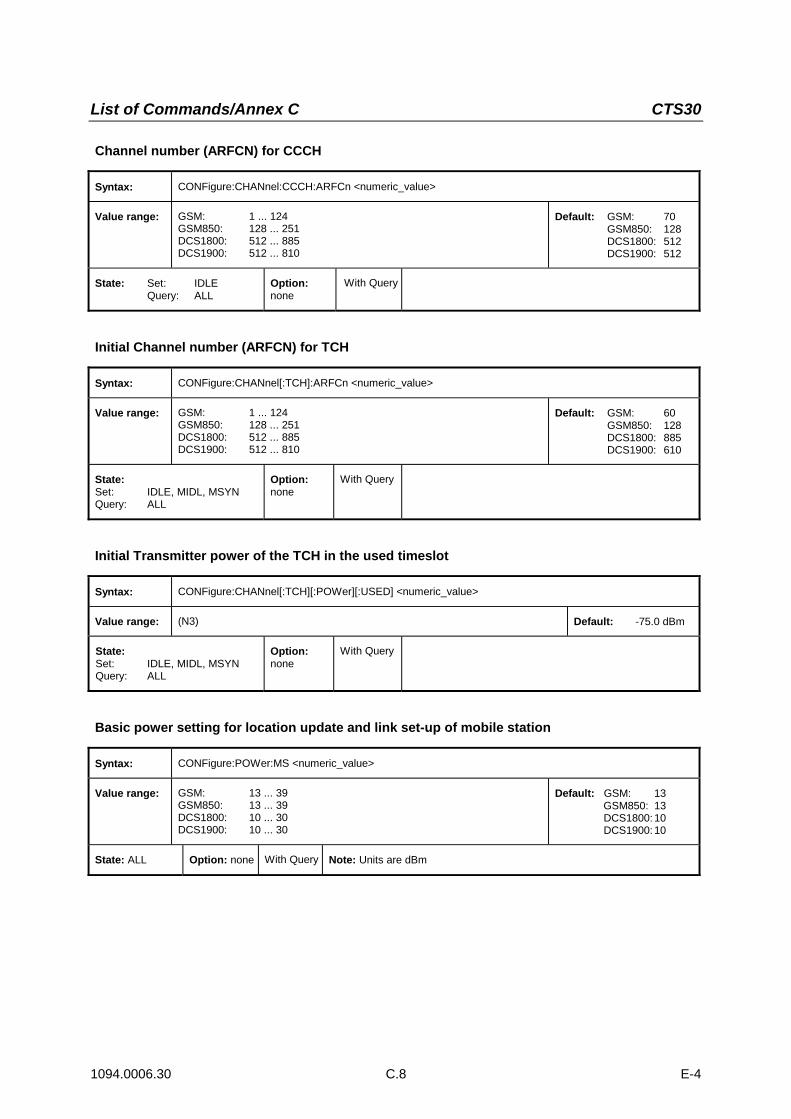
List of Commands/Annex C CTS30
1094.0006.30 C.8 E-4
Channel number (ARFCN) for CCCH
Syntax: CONFigure:CHANnel:CCCH:ARFCn <numeric_value>
Value range: GSM: 1 ... 124 GSM850: 128 ... 251 DCS1800: 512 ... 885 DCS1900: 512 ... 810
Default: GSM: 70 GSM850: 128 DCS1800: 512 DCS1900: 512
State: Set: IDLE Query: ALL
Option: none
With Query
Initial Channel number (ARFCN) for TCH
Syntax: CONFigure:CHANnel[:TCH]:ARFCn <numeric_value>
Value range: GSM: 1 ... 124 GSM850: 128 ... 251 DCS1800: 512 ... 885 DCS1900: 512 ... 810
Default: GSM: 60 GSM850: 128 DCS1800: 885 DCS1900: 610
State: Set: IDLE, MIDL, MSYN Query: ALL
Option: none
With Query
Initial Transmitter power of the TCH in the used timeslot
Syntax: CONFigure:CHANnel[:TCH][:POWer][:USED] <numeric_value>
Value range: (N3) Default: -75.0 dBm
State: Set: IDLE, MIDL, MSYN Query: ALL
Option: none
With Query
Basic power setting for location update and link set-up of mobile station
Syntax: CONFigure:POWer:MS <numeric_value>
Value range: GSM: 13 ... 39 GSM850: 13 ... 39 DCS1800: 10 ... 30 DCS1900: 10 ... 30
Default: GSM: 13 GSM850: 13 DCS1800: 10 DCS1900: 10
State: ALL Option: none With Query Note: Units are dBm

CTS30 List of Commands/Annex C
1094.0006.30 C.9 E-4
Networks for dualband handover
Syntax: CONFigure:SIGNalling:HANDover:NETWORK <value>
Value range:
Current Network GSM900
SING | handover not permitted, channel change in GSM900
D180 | handover possible between GSM900 & GSM1800
D190 | handover possible between GSM900 and GSM1900
MULTI | handover possible between GSM900/1800 or
GSM900/1900. (MS permitting)
Current Network GSM850
SING | handover not permitted, channel change in GSM900
D190 | handover possible between GSM850 & GSM1900
MULTI | handover possible between GSM900/1800 or
GSM900/1900. (MS permitting)
Current Network GSM1800
SING | handover not permitted, channel change in GSM1800
D180 | handover possible between GSM900 and GSM1800
MULTI | handover possible between GSM900/1800 or
GSM900/1900. (MS permitting)
Current Network GSM1900
SING | handover not permitted, channel change in GSM1900
D85 | handover possible between GSM1900 and GSM850
D190 | handover possible between GSM900 and GSM1900
MULTI | handover possible between GSM900/1800 or
GSM900/1900. (MS permitting)
Defaults: GSM900 SING GSM850 SING GSM1800 SING
GSM1900
SING
State: Set: IDLE Query: ALL
Option: none
With Query Note:
Checking the dualband handover with GSM900/GSM1800
Syntax: CONFigure:SIGNalling:HANDover:CHECK <value>
Value range:
SLOW | with handover check of the mobile
FAST | without handover check of the mobile
Default: SLOW
State: Set: IDLE Query: ALL
Option: none
With Query Note: The selected setting is taken into account when a handover between GSM900 and GSM1800 is selected
Dualband handover mode
Syntax: CONFigure:SIGNalling:HANDover:MODE <value>
Value range: BCCH | with control channel after handover
LEVEL | without control channel after handover
Default: LEVEL
State: Set: IDLE Query: ALL
Option: none
With Query Note:
Handover is initiated by using Change of channel for TCH.

List of Commands/Annex C CTS30
1094.0006.30 C.10 E-4
Configure access classes bit mask
Syntax: CONFigure:SIGNalling:ACLAss[?]
Value range: Decimal: 0-65535 Hexadecimal: 0-FFFF
Default: 00
State: IDLE
Option: none With query Note: The value represents the bit mask for 16 classes. Example: decimal value 31 (hex #H1F)
corresponds to bit mask 0000 0000 0001 1111 and classes 0,1,2,3,4 will be barred from access.
Configurable SMS message
Syntax: configure:sms?
Value range: Message content or “No Message” Default:
State: Set: ALL Query: ALL
Option: none With Query
Returns the SMS message content sent by the MS to the CTS and resets it to “No Message”
Syntax: configure:user:sms[?]
Value range: Message content Default:
State: Set: ALL Query: ALL
Option: none With Query
Set the SMS message content to be sent from the MS to the CTS.
Syntax: procedure:set:sms:oa:length[?]
Value range: 2 - 12 Default: 2
State: Set: ALL Query: ALL
Option: none With Query
Set the length of the TP Originator field of the SMS message to be sent from the CTS to the MS

CTS30 List of Commands/Annex C
1094.0006.30 C.11 E-4
1.2.3 Network and Test Mode
Network
Syntax: CONFigure:NETWork[:TYPE] <value>
Value range: GSM | G09 | GSM850 | G08 | DCS1800 | G18 | PCS1900 | G19
Default: GSM
State: Set: IDLE Query: ALL
Option: none With Query A Query returns G09, G18 or G19
Test Mode
Syntax: PROCedure:SELect[:TEST] <string>
Value range: NONE | No test mode (initial state) MIDL | MS-test MODidle | Module test IQSPec | IQ-spectrum BANalysis | Burst Analysis RFG | Rf generator
Default: NONE
State: (NONE): MIDL, MOD (MIDL): NONE (MODIDLE): IDLE, IQSP, BAN (IQSPEC): MOD, RFG (BANALYSIS): MOD, RFG (RFG): IQSP, BAN
Option: none none B7 B7 B7 B7
With Query Note:
Use the command STATus:DEVice? to query the state of the CTS.

List of Commands/Annex C CTS30
1094.0006.30 C.12 E-4
1.2.4 Call Set-up and Release
Call set-up from the CTS to the mobile (call)
Syntax: PROCedure:CALL:TOMS
State: MSYN Option: none No Query
Call release from the CTS to the mobile (Release)
Syntax: PROCedure:RELease:TOMS
State: MCE Option: none No Query
Change of channel for TCH
Syntax: PROCedure:SET:ARFCn <numeric_value>
Value range: GSM: 1 ... 124 *[975 … 1023] **[955 … 974]
GSM850 128 … 251 DCS1800: 512 ... 885 DCS1900: 512 ... 810
Default: this command takes the current value for the Initial Channel number (ARFCN) for TCH ( C.7)
State: MCE
Option: none
With query Note:
* Available for Mobile Stations which support E-GSM. ** Available for Mobile Stations which support R-GSM.
Power change (Mobile Station, used timeslot only)
Syntax: PROCedure:SET:POWer:MS <numeric_value>
Value range: GSM: 5 ... 15 | Power Control Level GSM850: 5 ... 15 | Power Control Level DCS1800: 0 ... 13* | Power Control Level DCS1900: 0 ... 13 | Power Control Level
State: MCE Option: none With Query Note: always returns the power control level (PCL), (N2)
∗ Max values may change for PHASEI and PHASEII mobiles
Power change (CTS) in unused timeslot
Syntax: CONFigure:BSSig:POWer <numeric_value> or PROCedure:SET:POWer:CMD[:USED] <numeric_value>
Value range: (N3)
State: MCE Option: keine With Query

CTS30 List of Commands/Annex C
1094.0006.30 C.13 E-4
1.3 Burst Analysis Settings
Channel number (ARFCN) and Frequency
Syntax: CONFigure:CHANnel:BANalysis:ARFCn <numeric_value>
Value range: GSM: -75 ... 450 GSM850: 128 ... 251 DCS1800: 461 ... 1511 DCS1900: -239 ... 811
Default: GSM: 65 GSM850: 251 DCS1800: 711 DCS1900: 661
State: BAN Option: B7 With Query
Syntax: CONFigure:CHANnel:BANalysis:ARFCn:FREQuency <numeric_value>
Value range: GSM: 875 ... 980 (in steps of 0.2 MHz) GSM850: 824 ... 894 (in steps of 0.2 MHz) DCS1800: 1700 ... 1910 (in steps of 0.2 MHz) DCS1900: 1700 ... 1910 (in steps of 0.2 MHz)
Default: GSM: 903 MHz GSM850: 869 MHz DCS1800: 1750 MHz DCS1900: 1880 MHz
State: BAN Option: B7 With Query
Training Sequence Codes
Syntax: CONFigure:CHANnel:BANalysis:TSC <numeric_value>
Value range: 0 ... 8 Default: 0
State: BAN Option: B7 With Query
Expected power (of mobile station)
Syntax: CONFigure:BANalysis:POWer:EXPected <numeric_value>
Value range: -15.0 ... +39.0 dBm Default: 0.0 dBm
State: BAN, IQSP Option: B7 With Query Note: (N3)
Trigger mode
Syntax: CONFigure:BANalysis:TRIGger:MODE <value>
Value range: POWer | Triggering on rising signal edge FREerun Triggering without edge detection
Default: POW
State: BAN Option: B7 With Query

List of Commands/Annex C CTS30
1094.0006.30 C.14 E-4
1.4 RF Generator Settings
Channel number
Syntax: CONFigure:RFGen:CHANnel[:CW| <numeric_value>
Value range: GSM: -175 ... 300 GSM850: 127...757 DCS1800: 511... 1436 DCS1900: -139 ... 811
Default: GSM: 1 GSM850: 127 DCS1800: 486 DCS1900: 611
State: RFG Option: B7 With Query
Frequency
Syntax: CONFigure:RFGen:FREQuency[:CW|:FIXed] <numeric_value>
Value range: GSM: 900.0 ... 995.0 MHz (in steps of 0.2 MHz) GSM850: 869.0 ... 995.0 MHz (in steps of 0.2 MHz) DCS1800: 1800.0 ... 1990.0 MHz (in steps of 0.2 MHz) DCS1900: 1800.0 ... 1990.0 MHz (in steps of 0.2 MHz)
Default: GSM: 935.2 MHz GSM850: 869.0 MHz DCS1800: 1800.0 MHz DCS1900: 1950.0 MHz
State: RFG Option: B7 With Query Note: The input value is adapted to the step size indicated when the parameter is set.
Frequency offset
Syntax: CONFigure:RFGen:FREQuency:OFFSet <numeric_value>
Value range: -100.009 ... 100.009 kHz Default: 0.0 Hz
State: RFG Option: B7 With Query
Type of modulation
Syntax: CONFigure:RFGen:DM:FORMat <value>
Value range: 0 ... 7 Default: 0
State: RFG Option: B7 With Query Note: Modulation must be in state dummy.
Modulation
Syntax: CONFigure:RFGen:DM:MODE <value>
Value range: OFF No modulation DUM Dummy burst with selected midamble AM Amplitude Modulation
Default: DUM
State: RFG Option: B7 With Query

CTS30 List of Commands/Annex C
1094.0006.30 C.15 E-4
Ramping Mode
Syntax: CONFigure:RFGen:RAMPing:STATe <value>
Value range: ON Signal with power ramping OFF Permanent signal
Default: OFF
State: RFG Option: B7 With Query
Output level
Syntax: CONFigure:RFGen:POWer <numeric_value>
Value range: (-110.0 - ext. att.) ... (-50.0 - ext. att.) dBm Default: -50.0 dBm
State: RFG Option: B7 With Query
RF Generator Level
Syntax: CONFigure:RFGen:LEVel <value>
Value range: ON Switched on OFF Switched off
Default: ON
State: RFG Option: B7 With Query

List of Commands/Annex C CTS30
1094.0006.30 C.16 E-4
1.5 Measurement, Analysis and Result Query
1.5.1 BER
1.5.1.1 Tolerances for the BER
Value for class-Ib Rate
Syntax: CONFigure:LIMit:BER:CLIB:RATE
Value range: 0.0 ... 100.0 Default: 0.4
State: ALL Option: none With Query
Value for class-II Rate
Syntax: CONFigure:LIMit:BER:CLII:RATE
Value range: 0.0 ... 100.0 Default: 2.6
State: ALL Option: none With Query
Values for erased frames Rate
Syntax: CONFigure:LIMit:BER:EFRames:RATE
Value range: 0.0 ... 100.0 Default: 1.0
State: ALL Option: none With Query
Number of frames to be sent
Syntax: CONFigure:BER:FRAMestosend <numeric_value>
Value range: 1 ... 499 Default: 100
State: ALL Option: none With Query

CTS30 List of Commands/Annex C
1094.0006.30 C.17 E-4
Maximal number of events
Syntax: CALCulate:LIMit:BER:CLIB:MEVents? CALCulate:LIMit:BER:CLII:MEVents? CALCulate:LIMit:BER:EFRames:MEVents?
Return: 0 ... 65868 (Class IB) 0 ... 38922 (Class II) 0 ... 499 (Erased Frames)
State: ALL Option: none Query only Note: The values are derived from "Frames to send" and thus cannot be set.
Maximal number of samples to be sent and test time
The maximal number of samples sent in the test is derived from the value for "Frames to send". These values are only reached in the test if the errors do not exceed the tolerances.
Syntax: CALCulate:BER:CLIB:MSAMples? CALCulate:BER:CLII:MSAMples? CALCulate:BER:EFRames:MSAMples? CALCulate:BER:TEST:TIME?
Return: 1320 ... 65868 (Class IB) 780 ... 38922 (Class II) 10 ... 499 (Erased Frames) 0.20 ... 9.98 (Test time, seconds)
State: ALL Option: none Query only Note: The values are derived from "Frames to send" and thus cannot be set.

List of Commands/Annex C CTS30
1094.0006.30 C.18 E-4
1.5.1.2 BER Measurement
Measured values of class Ib
Syntax: Execute new measurement and signal result Read result only
READ[:SCALar]:BER:CLIB[:BER]? READ[:SCALar]:BER:CLIB:RBER? FETCh[:SCALar]:BER:CLIB[:BER]? FETCh[:SCALar]:BER:CLIB:RBER?
Return: BER and RBER: 0 ... 100 (Unit: %)
State: MCE Option: none Query only Note: No default values, (N4)
If a read is performed on BER, all subsequent fetches will return BER values until a RBER read is carried out. The same applies for RBER
Measured values of class II
Syntax: Execute new measurement and signal result Read result only
READ[:SCALar]:BER:CLII[:BER]? READ[:SCALar]:BER:CLII:RBER?
FETCh[:SCALar]:BER:CLII[:BER]? FETCh[:SCALar]:BER:CLII:RBER?
Return: BER and RBER: 0 ... 100 (Unit: %)
State: MCE Option: none Query only Note: No default values, (N4)
If a read is performed on BER, all subsequent fetches will return BER values until a RBER read is carried out. The same applies for RBER
Measured values of erased frames
Syntax: Execute new measurement and signal result Read result only
READ[:SCALar]:BER:EFRames[:FER]?
FETCh[:SCALar]:BER:EFRames[:FER]?
Return: BER and RBER: 0 ... 100 (Unit: %)
State: MCE Option: none Query only Note: No default values, (N4)

CTS30 List of Commands/Annex C
1094.0006.30 C.19 E-4
1.5.2 Power
1.5.2.1 Tolerances for Power
Resetting to default values
Syntax: CALCulate:LIMit:POWer[:TEMPlate]:CLEar
State: ALL Option: none No Query Note: Resets the GSM, GSM850, DCS1800 and DCS1900 tolerances
Tolerances for average power in the power time template
Syntax: CALCulate:LIMit:POWer[:TEMPlate]:TOLerance1[:DATA] <numeric_value> CALCulate:LIMit:POWer[:TEMPlate]:TOLerance2[:DATA] <numeric_value>
Value range: Deviation from expected value GSM and GSM850: CALC:LIM:POW:TOL1 0.0 ... +9.9 dB with maximum power control level CALC:LIM:POW:TOL2 0.0 ... +9.9 dB with all other power control levels DCS1800 and DCS1900: CALC:LIM:POW:TOL1 0.0 ... +9.0 dB with maximum power control level CALC:LIM:POW:TOL2 0.0 ... +9.0 dB up to power control level 8
Default: GSM: TOL1 +2.0 dBTOL2 +3.0 dB DCS1800: TOL1 +3.0 dBTOL2 +3.0 dB
DCS1900: TOL1 +3.0 dBTOL2 +4.0 dB
State: ALL Option: none With Query Note: The deviations always apply symmetrically about the expected value

List of Commands/Annex C CTS30
1094.0006.30 C.20 E-4
Tolerances for power time template
The level designations used in the power time template for the command CALCulate:LIMit:POWer[:TEMPlate][:DATA] can be obtained from the following illustration:
A
B
C
D
E
F G
H
A
Syntax: CALCulate:LIMit:POWer[:TEMPlate][:DATA]
<numeric_value>, <numeric_value>, <numeric_value>, <numeric_value>, <numeric_value>, <numeric_value>, <numeric_value>, <numeric_value>, <numeric_value>
Value range: -100.0 ... 0.0 dBm Absolute level at A -100.0 ... 0.0 dB Relative level at A -100.0 ... 0.0 dB Relative level at B -100.0 ... 0.0 dB Relative level at C 0.0 ... +20.0 dB Relative level at D 0.0 ... +5.0 dB Relative level at E -5.0 ... 0.0 dB Relative level at F -100.0 ... 0.0 dB Relative level at G -100.0 ... 0.0 dB Relative level at H
Default: GSM: -36.0 dBm GSM850: -36.0 dBm DCS1800: -47.0 dBm DCS1900: -47.0 dBm -45.0 dB -30.0 dB -6.0 dB +4.0 dB +1.0 dB -1.0 dB -6.0 dB -30.0 dB
State: ALL Option: none With Query
Query for observance of the tolerances for average power
Syntax: CALCulate:LIMit:POWer[:TEMPlate]:TOLerance:MATChing?
Return: (MATC | NMAT | INV)
State: MCE Option: none Query only Note: returns the result from the last measurement, (N5), (N6)

CTS30 List of Commands/Annex C
1094.0006.30 C.21 E-4
Query for observance of the tolerances of the power/time template
Syntax: CALCulate:LIMit:POWer[:TEMPlate]:MATChing?
Return: MATC | in Tolerance NMAT | out of Tolerance INV | no measurement result available NRAM | no ramping NTSC | no valid TSC found OUT | Out of dynamic range TEAR | falling edge of ramp too early THIG | value of Phase/Frequency error too high TLAT | rising edge of ramp too late TLON | Burst too long TSH Burst too short
State: MCE, RFG, BAN
Option: none Query only Note: returns the result from the last measurement, (N5), (N6)

List of Commands/Annex C CTS30
1094.0006.30 C.22 E-4
1.5.2.2 Power Measurement
Average power of the burst
Syntax: Execute new measurement and signal result
Read result only
READ[:SCALar]:BURSt:POWer:AVERage?
FETCh[:SCALar]:BURSt:POWer:AVERage?
Return: <value> (unit: dBm)
State: MCE, RFG, BAN
Option: none Query only Note: No default values, (N5)
Power values of the burst
Syntax: Execute new measurement and signal result Read result only
READ:ARRay:BURSt:POWer? FETCh:ARRay:BURSt:POWer?
Return: <value> {, <value>} (unit: dB)
State: MCE, RFG, BAN
Option: none Query only Note: No default values, (N5)
Peakvalue of the power
Syntax: Execute new measurement and signal result
SENSe:POWer:PEAK?
Return: <value> (unit: dBm)
State: MCE, RFG, BAN
Option: none Query only Note: No default values, (N5)
Power Measurement Mode Status
Syntax: SENse:MODuletest:MEASurement:MODE?
Value range: "SENSITIVE" "NORMAL"
Default: "NORMAL"
State: MOD
Option: Only query Note:

CTS30 List of Commands/Annex C
1094.0006.30 C.23 E-4
Sensitive Power Measurement Offset
Syntax: CONFigure:MODuletest:SPM:OFFSet[?]
Value range: -10 dB +10 dB
Default: 2 dB
State: MOD
Option: Note: This value can also be adjusted automatically by the SPM calibration routine.
Calibration Routine Start
Syntax: PROCedure:CALibrate:SPM?
Value range: "CALIBRATION_OK", "CALIBRATION_FAILED_WRONG_FREQUENCY", "CALIBRATION_FAILED_INVALID_SIGNAL", "CALIBRATION_FAILED_UNSTABLE_SIGNAL"
Default:
State: MOD
Option: Only query Note: This command starts the SPM calibration routine.

List of Commands/Annex C CTS30
1094.0006.30 C.24 E-4
1.5.3 Phase and Frequency Errors
1.5.3.1 Tolerances for Phase and Frequency Errors
Resetting to default values
Syntax: CALCulate:LIMit:PHFR:CLEar
State: ALL Option: none No Query Note: Sets the GSM,GSM850, DCS1800 or DCS1900 tolerances
Tolerances for phase and frequency error
Syntax: CALCulate:LIMit:PHFR:TOLerance[:DATA] <numeric_value>, <numeric_value>, <numeric_value>
Value range: 0.0 ... 100.0 deg (Peak phase error) 0.0 ... 25.0 deg (RMS phase error) GSM: 0 ... 200 Hz (Frequency error) GSM850: 0 ... 200 Hz (Frequency error) DCS1800: 0 ... 400 Hz DCS1900: 0 ... 400 Hz
Default: 20.0 deg 5.0 deg GSM: 90 Hz GSM850: 90 Hz DCS1800: 180 Hz DCS1900: 180 Hz
State: ALL Option: none With Query
Query for observance of tolerances
Syntax: CALCulate:LIMit:PHFR:TOLerance:MATChing?
Return: (MATC | NMAT | INV), (Peak phase error) (MATC | NMAT | INV), (RMS phase error) (MATC | NMAT | INV) (Frequency error)
State: MCE, RFG, BAN
Option: none Query only Note: Supplies the result for the last measurement, (N5), (N6)
Query for observance of the tolerances (average and maximum value measurement)
Syntax: CALCulate:LIMit:PHFR:TOLerance:MATChing:AVERage? CALCulate:LIMit:PHFR:TOLerance:MATChing:MAXimum?
Return: (MATC | NMAT | INV), (Peak phase error) (MATC | NMAT | INV), (RMS phase error) (MATC | NMAT | INV) (Frequency error)
State: MCE, RFG, BAN
Option: none Query only Note: Supplies the result for the last measurement, (N5), (N6)

CTS30 List of Commands/Annex C
1094.0006.30 C.25 E-4
1.5.3.2 Test Parameters for Phase and Frequency Error Measurements
Number of bursts for average- and maximum-value measurements
Syntax: CALCulate:LIMit:PHFR:AVERage
Value range: 1 ... 999
Default: 10
State: ALL Option: none With Query

List of Commands/Annex C CTS30
1094.0006.30 C.26 E-4
1.5.3.3 Phase Error Measurement
Total phase error of a burst
Syntax: Execute new measurement and signal result Read result only
RMS: READ[:SCALar]:BURSt:PHASe:ERRor:RMS? Peak: READ[:SCALar]:BURSt:PHASe:ERRor:PEAK? RMS: FETCh[:SCALar]:BURSt:PHASe:ERRor:RMS? Peak: FETCh[:SCALar]:BURSt:PHASe:ERRor:PEAK?
Return: <value> (current, unit: °) <value> (average, unit: °) <value> (maximum, unit: °)
State: MCE, RFG, BAN
Option: none Query only Note: No default values, (N5)
Phase error values of the burst
Syntax: Execute new measurement and signal result Read result only
READ:ARRay:BURSt:PHASe:ERRor?
FETCh:ARRay:BURSt:PHASe:ERRor?
Return: <value> {, <value>} (unit: °)
State: MCE, RFG, BAN
Option: none Query only Note: No default values, (N5)

CTS30 List of Commands/Annex C
1094.0006.30 C.27 E-4
1.5.3.4 Frequency Error Measurement
Total frequency error of a burst
Syntax: Execute new measurement and signal result Read result only
READ[:SCALar]:BURSt:FREQuency:ERRor?
FETCh[:SCALar]:BURSt:FREQuency:ERRor?
Return: <value> (current, unit: Hz) <value> (average, unit: Hz) <value> (maximum, unit: Hz)
State: MCE, RFG, BAN
Option: none Query only Note: No default values, (N5)
1.5.4 Timing Measurement
Syntax: Execute new measurement and signal result Read result only
READ[:SCALar]:BURSt:TIMing:ERRor?
FETCh[:SCALar]:BURSt:TIMing:ERRor?
Return: <value> (unit: Bit)
State: MCE Option: none Query only Note: No default values, (N5)

List of Commands/Annex C CTS30
1094.0006.30 C.28 E-4
1.5.5 IQ Spectrum Measurement
1.5.5.1 Settings for IQ Spectrum Measurement
Channel number (ARFCN) and Frequency
Syntax: CONFigure:CHANnel:IQSPectrum:ARFCn <numeric_value>
Value range: GSM: -74 ... 449 GSM850: 128 ... 251 DCS1800: 462 ... 1510 DCS1900: -238 ... 810
Default: GSM: 50 GSM850: 251 DCS1800: 711 DCS1900: 661
State: ALL Option: B7 With Query
Syntax: CONFigure:CHANnel:IQSPectrum:ARFCn:FREQuency <numeric_value>
Value range: GSM: 875.2 ... 989.8 (in steps of 0.2 MHz) GSM850: 824.2 ... 893.8 (in steps of 0.2 MHz) DCS1800: 1800.2 ... 1989.8 (in steps of 0.2 MHz) DCS1900: 1700.2 ... 1909.8 (in steps of 0.2 MHz)
Default: GSM: 903 MHz GSM850: 869 MHz DCS1800: 1750 MHz DCS1900: 1880 MHz
State: ALL Option: B7 With Query
Signal setting
Syntax: CONFigure:IQSPectrum:MODE <value>
Value range: CW | Continuous signal BURSt Pulsed signal
Default: BURSt
State: IDLE, MOD
Option: B7 With Query
Bandwidth
Syntax: CONFigure:IQSPectrum:BANDwidth[:RESolution] <value>
Value range: B4 | Bandwidth 4 kHz B10 | Bandwidth 10 kHz B20 | Bandwidth 20 kHz B50 | Bandwidth 50 kHz B100 Bandwidth 100 kHz
Default: B4
State: IDLE, MOD
Option: B7 With Query

CTS30 List of Commands/Annex C
1094.0006.30 C.29 E-4
Average value
Syntax: CONFigure:IQSPectrum:AVERage[:COUNt] <value>
Value range: <value> 1 … 50 Default: 1
State: IDLE, MOD
Option: B7 With Query
1.5.5.2 Measurements
Spectrum measurement
Syntax: Execute new measurement and signal result Read result only
READ:ARRay:IQSPectrum?
FETCh:ARRay:IQSPectrum?
Return: <value> {, <value>} (unit: dB; maximum 300 values, -150 kHz -> +150 kHz)
State: IQSP Option: B7 Query only Note: No default value
Measurement of reference power
Syntax: Execute new measurement and signal result Read result only
READ[:SCALar]:IQSPectrum:POWer[:REFerence]?
FETCh[:SCALar]:IQSPectrum:POWer[:REFerence]?
Return: <value> (unit: dBm)
State: IQSP Option: B7 Query only Note: No default value

List of Commands/Annex C CTS30
1094.0006.30 C.30 E-4
1.5.6 GPRS and BLER Measurement
Enable/disable GPRS
Syntax: CONFigure:GPRS:STATe?
Value range: ON, OFF
Default: OFF
State: IDLE Option: K4 With query Note:
GPRS Signalling State
Syntax: SENSe:GPRS:SIGNalling:STATe?
Value range: ATTACHED, NOT ATTACHED
Default:
State: MSYN Option: K4 Only query Note:
Configure Uplink State Flag (USF)
Syntax: CONFigure:SIGNalling:IDENtity:USF?
Value range: 0 - 7 Default: 0
State: IDLE,MSYN Option: K4 With query Note:
Configure Routing Area Code (RAC)
Syntax: CONFigure:SIGNalling:IDENtity:RAC?
Value range: 0 - 255 Default: 0
State: IDLE,MSYN Option: K4 With query Note:
Configure GPRS Coding Scheme
Syntax: CONFigure:GPRS:BLER:CODIngscheme[?]
Value range: CS1 CS2 CS3 CS4
Default: CS1
State: IDLE,MSYN Option: K4 With query Note:

CTS30 List of Commands/Annex C
1094.0006.30 C.31 E-4
Configure number of blocks for the BLER measurement
Syntax: CONFigure:GPRS:BLER:BLOCkstosend[?]
Value range: 10 - 9999 Default: 1000
State: IDLE,MSYN
Option: K4 With query Note:
GPRS BLER measurement on/off
Syntax: CONFigure:GPRS:BLER:State[?]
Value range: ON,OFF
Default:
State: MSYN
Option: K4 With query Note: This command does establish and release TBF and changes the state of the instrument to BLER.
Measured values of the error rate
Syntax:
Execute new measurement and signal result
Read result only
READ:GPRS:BLER:ERROrrate[?] FETCh:GPRS:BLER:ERROrrate[?]
Value range: 0 ... 100 (Unit: %) Default:
State: BLER
Option: K4 With query Note: If a read is performed on BLER, all subsequent fetches will return error rate value until a BLER read is carried out.
Measured values of the data rate
Syntax:
Execute new measurement and signal result
Read result only
READ:GPRS:BLER:DATArate[?] FETCh:GPRS:BLER:DATArate[?]
Value range: Default:
State: BLER
Option: K4 With query Note: If a read is performed on BLER, all subsequent fetches will return data rate value until a BLER read is carried out.

List of Commands/Annex C CTS30
1094.0006.30 C.32 E-4
1.6 Miscellaneous
1.6.1 Internal Instrument State
Current instrument state
Syntax: STATus:DEVice?
Return: IDLE | Idle (initial state) MIDL | MS test: Idle MSYN | MS test: Synched MCE | MS test: Call established MOD | Module test Idle IQSP | IQ-spectrum BAN | Burst Analysis RFG RF generator
Default: IDLE
State: ALL Option: none Query only
1.6.2 Mobile Station Details
Query for Mobile Stations Extended GSM capabilities
Syntax: CALCulate:MOBILE:EGSM:STATus?
Return: NSUP Not Supported SUPP Supported
State: MSYN or MCE
Option: none Query only Default: NSUP
Query for Mobile Stations Dual Band capabilities
Syntax: CALCulate:MOBILE:DBHO:STATus?
Return: NSUP Not Supported SUPP Supported
State: MSYN or MCE
Option: none Query only Note: Capability for 850/ 900 / 1800MHz only.
Default: NSUP

CTS30 List of Commands/Annex C
1094.0006.30 C.33 E-4
Query for Mobile Stations Enhanced Full Rate capabilities
Syntax: CALCulate:MOBILE:EFRC:STATus?
Return: NSUP Not Supported SUPP Supported
State: MCE Option: none Query only Default: NSUP
Query for Mobile Stations Half Rate capabilities
Syntax: CALCulate:MOBILE:HRC:STATus?
Return: NSUP Not Supported SUPP Supported
State: MCE Option: none Query only Default: NSUP
MS HSCSD multislot capabilities
Syntax: SENSe:GPRS:HSCSd:CLASs?
Value range: "-" - parameter is not available “A(B Dn/C Up/D Sum” , where
A is a number of uplink slots B is a number of downlink slots C is a multislot class number D is maximum available number of slots
Default:
State: MSYN
Option: K4 Only query Note:
MS GPRS multislot capabilities
Syntax: SENSe:GPRS:GPRS:CLASs?
Value range: "-" - parameter is not available “A(B Dn/C Up/D Sum”, where
A is a number of uplink slots B is a number of downlink slots C is a multislot class number D is maximum available number of slots
Default:
State: MSYN Option: K4 Only query Note:

List of Commands/Annex C CTS30
1094.0006.30 C.34 E-4
MS RGSM status
Syntax: CALCulate:MOBIle:RGSM:STATus?
Value range: NSUP – not supported SUPP – supported
Default:
State: MSYN
Option: none Only query Note:
1.6.3 Write to Hard Disk
Write Settings to Hard Disk
Syntax: PROCedure:SET:WRIte:HD?
Return: ON All changes are saved to hard disk OFF No new changes are saved to hard disk
State: ALL Option: none With Query Note: Not effected by *RST.
Default: ON

CTS30 List of Commands/Annex C
1094.0006.30 C.35 E-4
1.7 Specified Commands
1.7.1 Mandatory Commands
Clear Status
Syntax: *CLS
State: ALL Option: none No Query
Standard Event Status Enable
Syntax: *ESE <numeric_value>
Value range: 0 ... 255 Default: 0
State: ALL Option: none With Query Note: MAXimum and MINimum impermissible
Standard Event Status Register
Syntax: *ESR?
Return: 0 ... 255
State: ALL Option: none Query only
Identification Query
Syntax: *IDN?
Return: ROHDE&SCHWARZ, CTSzz, .ssssss/sss, xx.xx yy.yy.yy (zz is the model no., eg 55, 60 or 65 ssssss/sss is the serial number of the testset, eg 123456/789 xx.xx is the software version, eg V 1.00 yy.yy.yy is the date, eg 18.10.93)
State: ALL Option: none Query only
Individual Status Query
Syntax: *IST?
Return: 0 | 1
State: ALL Option: none Query only

List of Commands/Annex C CTS30
1094.0006.30 C.36 E-4
Operation Complete
Syntax: *OPC
Return: 1 (return only in the case of query)
State: ALL Option: none With Query Note: Also influences the OPC bit in the event status register
Parallel Poll Enable Register Enable
Syntax: *PRE <numeric_value>
Value range: 0 ... 255 Default: 0
State: ALL Option: none With Query Note: MAXimum and MINimum impermissible
Power-on Status Clear
Syntax: *PSC <numeric_value>
Value range: -32767 ... 32767 Default: 1
State: ALL Option: none With Query Note: MAXimum and MINimum impermissible
Service Request Enable
Syntax: *SRE <numeric_value>
Value range: 0 ... 255 Default: 0
State: ALL Option: none With Query Note: MAXimum and MINimum impermissible

CTS30 List of Commands/Annex C
1094.0006.30 C.37 E-4
Status Byte Query
Syntax: *STB?
Return: 0 ... 255
State: ALL Option: none Query only
Wait-to-Continue
Syntax: *WAI
State: ALL Option: none No Query

List of Commands/Annex C CTS30
1094.0006.30 C.38 E-4
1.8 Remarks
1.8.1 (N1) -) The transmitter power is adapted, if necessary (see also (N3)).
-) The input may be overdriven if an external amplifier is connected.
-) The settings have only influence on the <default mobile>. It should be selected previously.
1.8.2 (N2) During signalling, RXLEV, RXQUAL and POWER LEVEL are automatically polled by the mobile at regular intervals and thus updated. The measurement for SENSe:POWer:MS? also runs automatically as soon as the connection is set up. 1.8.3 (N3) -) The value is valid irrespective of the output and is automatically adapted to the output on transition to
the MIDL state, which may cause the value range to be shifted.
-) The value applies to the currently set timeslot of the TCH.
-) For the value range see Manual Operation, section 2.
1.8.4 (N4) Using a READ command, a new measurement is started and the desired value(s) returned. The result of this measurement can be repeatedly read by using a FETCh query without performing a new measurement. The FETCh command should only be used after a read has been executed otherwise initialisation values will be returned. 1.8.5 (N5) After calling of a READ command, all scalar measurement results (average power, RMS and peak phase error and frequency error) are calculated and the desired value is returned; the remaining measurement results can be fetched using FETCh or CALCulate. However, if the measurement is made via READ:ARRay, the scalar values are available in addition to the selected field values. The measurement of the field values of the power (READ:ARRay:BURSt:POWer?) and phase error (READ:ARRay:BURSt:PHASe:ERRor?) are mutually exclusive, i.e. after READ:ARRay:BURSt:POWer? it is not possible to fetch the phase errors by means of FETCh:ARRay:BURSt:PHASe:ERRor?. The timing is measured when the power field values are measured, but not when the phase error is measured. 1.8.6 (N6) The results of the tolerance query have the following meaning:
MATC: The measurement result observes the configured limit values NMAT: The measurement result does not observe the configured limit values
INV: No measurement result is available
1.8.7 (N7) If a READ measurement command cannot be performed, the CTS will return NAN (Not A Number), to indicate a non-valid result. A FETCh command will also return NAN either after a non-valid measurement or if no measurement has been performed previously.

CTS30 List of Commands/Annex C
1094.0006.30 C.39 E-4
1.9 Index
* *CLS ............................................................................................................................................................................................35 *ESE <numeric_value> ................................................................................................................................................................35 *ESR? ..........................................................................................................................................................................................35 *IDN? ...........................................................................................................................................................................................35 *IST?............................................................................................................................................................................................35 *OPC............................................................................................................................................................................................36 *PRE <numeric_value> ................................................................................................................................................................36 *PSC <numeric_value> ................................................................................................................................................................36 *SRE <numeric_value> ................................................................................................................................................................36 *STB? ..........................................................................................................................................................................................37 *WAI.............................................................................................................................................................................................37
C CALCulate:BER:CLIB:MSAMples?...............................................................................................................................................17 CALCulate:BER:CLII:MSAMples?................................................................................................................................................17 CALCulate:BER:EFRames:MSAMples?.......................................................................................................................................17 CALCulate:BER:TEST:TIME?......................................................................................................................................................17 CALCulate:LIMit:BER:CLIB:MEVents?.........................................................................................................................................17 CALCulate:LIMit:BER:CLII:MEVents?..........................................................................................................................................17 CALCulate:LIMit:BER:EFRames:MEVents?.................................................................................................................................17 CALCulate:LIMit:PHFR:AVERage................................................................................................................................................25 CALCulate:LIMit:PHFR:CLEar .....................................................................................................................................................24 CALCulate:LIMit:PHFR:TOLerance:MATChing:AVERage?..........................................................................................................24 CALCulate:LIMit:PHFR:TOLerance:MATChing:MAXimum? .........................................................................................................24 CALCulate:LIMit:PHFR:TOLerance:MATChing? ..........................................................................................................................24 CALCulate:LIMit:PHFR:TOLerance[:DATA] <numeric_value>, <numeric_value>, <numeric_value>............................................24 CALCulate:LIMit:POWer[:TEMPlate]:CLEar .................................................................................................................................19 CALCulate:LIMit:POWer[:TEMPlate]:MATChing? ........................................................................................................................21 CALCulate:LIMit:POWer[:TEMPlate]:TOLerance:MATChing?......................................................................................................20 CALCulate:LIMit:POWer[:TEMPlate]:TOLerance1[:DATA] <numeric_value> ...............................................................................19 CALCulate:LIMit:POWer[:TEMPlate]:TOLerance2[:DATA] <numeric_value> ...............................................................................19 CALCulate:LIMit:POWer[:TEMPlate][:DATA] ...............................................................................................................................20 CALCulate:MOBILE:DBHO:STATus? ..........................................................................................................................................32 CALCulate:MOBILE:EFRC:STATus? ...........................................................................................................................................33 CALCulate:MOBILE:EGSM:STATus? ..........................................................................................................................................32 CALCulate:MOBILE:HRC:STATus? .............................................................................................................................................33 CONFigure:BANalysis:POWer:EXPected <numeric_value>.........................................................................................................13 CONFigure:BANalysis:TRIGger:MODE <value> ..........................................................................................................................13 CONFigure:BER:FRAMestosend <numeric_value> .....................................................................................................................16 CONFigure:BSSig:POWer <numeric_value>................................................................................................................................12 CONFigure:CHANnel:BANalysis:ARFCn <numeric_value>..........................................................................................................13 CONFigure:CHANnel:BANalysis:ARFCn:FREQuency <numeric_value> .....................................................................................13 CONFigure:CHANnel:BANalysis:TSC <numeric_value> ..............................................................................................................13 CONFigure:CHANnel:CCCH:ARFCn <numeric_value>..................................................................................................................8 CONFigure:CHANnel:IQSPectrum:ARFCn <numeric_value>.......................................................................................................28 CONFigure:CHANnel:IQSPectrum:ARFCn:FREQuency <numeric_value> ..................................................................................28 CONFigure:CHANnel[:TCH]:ARFCn <numeric_value>...................................................................................................................8 CONFigure:CHANnel[:TCH][:POWer][:USED] <numeric_value>....................................................................................................8 CONFigure:IQSPectrum:AVERage[:COUNt] <value> ..................................................................................................................29 CONFigure:IQSPectrum:BANDwidth[:RESolution] <value>..........................................................................................................28 CONFigure:IQSPectrum:MODE <value>......................................................................................................................................28 CONFigure:LIMit:BER:CLIB:RATE...............................................................................................................................................16 CONFigure:LIMit:BER:CLII:RATE ................................................................................................................................................16 CONFigure:LIMit:BER:EFRames:RATE.......................................................................................................................................16 CONFigure:NETWork[:TYPE] <value>.........................................................................................................................................11 CONFigure:POWer:MS <numeric_value> ......................................................................................................................................8 CONFigure:RFGen:CHANnel[:CW| <numeric_value> ..................................................................................................................14 CONFigure:RFGen:DM:FORMat <value> ....................................................................................................................................14 CONFigure:RFGen:DM:MODE <value> ......................................................................................................................................14 CONFigure:RFGen:FREQuency:OFFSet <numeric_value> .........................................................................................................14 CONFigure:RFGen:FREQuency[:CW|:FIXed] <numeric_value> ..................................................................................................14 CONFigure:RFGen:LEVel <value>..............................................................................................................................................15 CONFigure:RFGen:POWer <numeric_value> ..............................................................................................................................15 CONFigure:RFGen:RAMPing:STATe <value> .............................................................................................................................15

List of Commands/Annex C CTS30
1094.0006.30 C.40 E-4
CONFigure:SIGNalling:IDENtity:LAC <numeric_value> .................................................................................................................7 CONFigure:SIGNalling:IDENtity:MCC <numeric_value> ................................................................................................................7 CONFigure:SIGNalling:IDENtity:MNC <numeric_value> ................................................................................................................7 CONFigure:SIGNalling:IDENtity:NCC <numeric_value>.................................................................................................................7
F FETCh:ARRay:BURSt:PHASe:ERRor?........................................................................................................................................26 FETCh:ARRay:BURSt:POWer? ...................................................................................................................................................22 FETCh:ARRay:IQSPectrum? .......................................................................................................................................................29 FETCh[:SCALar]:BER:CLIB:RBER? ............................................................................................................................................18 FETCh[:SCALar]:BER:CLIB[:BER]?.............................................................................................................................................18 FETCh[:SCALar]:BER:CLII:RBER?..............................................................................................................................................18 FETCh[:SCALar]:BER:CLII[:BER]? ..............................................................................................................................................18 FETCh[:SCALar]:BER:EFRames[:FER]? .....................................................................................................................................18 FETCh[:SCALar]:BURSt:FREQuency:ERRor?.............................................................................................................................27 FETCh[:SCALar]:BURSt:PHASe:ERRor:PEAK?..........................................................................................................................26 FETCh[:SCALar]:BURSt:PHASe:ERRor:RMS?............................................................................................................................26 FETCh[:SCALar]:BURSt:POWer:AVERage? ...............................................................................................................................22 FETCh[:SCALar]:BURSt:TIMing:ERRor? .....................................................................................................................................27 FETCh[:SCALar]:IQSPectrum:POWer[:REFerence]?...................................................................................................................29
P PROCedure:CALL:TOMS.............................................................................................................................................................12 PROCedure:RELease:TOMS.......................................................................................................................................................12 PROCedure:SELect[:TEST] <string> ...........................................................................................................................................11 PROCedure:SET:POWer:CMD[:USED] <numeric_value> ...........................................................................................................12 PROCedure:SET:POWer:MS <numeric_value>...........................................................................................................................12 PROCedure:SET:WRIte:HD.........................................................................................................................................................34
R READ:ARRay:BURSt:PHASe:ERRor?.........................................................................................................................................26 READ:ARRay:BURSt:POWer? ....................................................................................................................................................22 READ:ARRay:IQSPectrum?.........................................................................................................................................................29 READ[:SCALar]:BER:CLIB:RBER?..............................................................................................................................................18 READ[:SCALar]:BER:CLIB[:BER]? ..............................................................................................................................................18 READ[:SCALar]:BER:CLII:RBER? ...............................................................................................................................................18 READ[:SCALar]:BER:CLII[:BER]?................................................................................................................................................18 READ[:SCALar]:BER:EFRames[:FER]?.......................................................................................................................................18 READ[:SCALar]:BURSt:FREQuency:ERRor? ..............................................................................................................................27 READ[:SCALar]:BURSt:PHASe:ERRor:PEAK? ...........................................................................................................................26 READ[:SCALar]:BURSt:PHASe:ERRor:RMS?.............................................................................................................................26 READ[:SCALar]:BURSt:POWer:AVERage?.................................................................................................................................22 READ[:SCALar]:BURSt:TIMing:ERRor?.......................................................................................................................................27 READ[:SCALar]:IQSPectrum:POWer[:REFerence]? ....................................................................................................................29
S SENSe:POWer:MS? ......................................................................................................................................................................6 SENSe:POWer:PEAK? ................................................................................................................................................................22 SENSe:SIGNalling:DNUMber?.......................................................................................................................................................6 SENSe:SIGNalling:IDENtity:IMEI? .................................................................................................................................................5 SENSe:SIGNalling:IDENtity:IMSI? .................................................................................................................................................5 SENSe:SIGNalling:IDENtity:MS:REVision:LEVel? .........................................................................................................................5 SENSe:SIGNalling:RXLev?............................................................................................................................................................5 SENSe:SIGNalling:RXQual? ..........................................................................................................................................................5 SOURce:CORRection:LOSS:COUPler <value> .............................................................................................................................4 STATus:DEVice? .........................................................................................................................................................................32

CTS30 MS Power Charts/Annex D
1094.0006.30 D.1 E-3
MS Power Charts Mobile Power Classes
GSM 900 DCS 1800 PCS 1900
Power Class Max. Peak Power (W) dBm Max. Peak Power (W) dBm Max. Peak Power (W) dBm
1 20 +43 1 +30 1 +30
2 8 +39 0.25 +24 0.25 +24
3 5 +37 --- --- 2 +33
4 2 +33 --- --- --- ---
5 0.8 +29 --- --- --- ---
Mobile Power Control Levels
Peak Power (dBm) Power Control Level GSM 900 DCS 1800 PCS 1900
0 +43 +30 +30
1 +41 +28 +28
2 +39 +26 +26
3 +37 +24 +24
4 +35 +22 +22
5 +33 +20 +20
6 +31 +18 +18
7 +29 +16 +16
8 +27 +14 +14
9 +25 +12 +12
10 +23 +10 +10
11 +21 +8 +8
12 +19 +6 +6
13 +17 +4 +4
14 +15 +2 +2
15 +13 0 0
16 to 29 reserved
30 +33
31 +32

MS Power Charts/Annex D CTS30
1094.0006.30 D.2 E-3
Rx_LEV Values
The reported Rx_LEV values for received signal level are as follows:
Rx_LEV Received Signal Level Rx_LEV Received Signal Level
0 Less than -110 dBm 33 -78 dBm to -77 dBm
1 -110 dBm to -109 dBm 34 -77 dBm to -76 dBm
2 -109 dBm to -108 dBm 35 -76 dBm to -75 dBm
3 -108 dBm to -107 dBm 36 -75 dBm to -74 dBm
4 -107 dBm to -106 dBm 37 -74 dBm to -73 dBm
5 -106 dBm to -105 dBm 38 -73 dBm to -72 dBm
6 -105 dBm to -104 dBm 39 -72 dBm to -71 dBm
7 -104 dBm to -103 dBm
8 -103 dBm to -102 dBm 40 -71 dBm to -70 dBm
9 -102 dBm to -101 dBm 41 -70 dBm to -69 dBm
42 -69 dBm to -68 dBm
10 -101 dBm to -100 dBm 43 -68 dBm to -67 dBm
11 -100 dBm to -99 dBm 44 -67 dBm to -66 dBm
12 -99 dBm to -98 dBm 45 -66 dBm to -65 dBm
13 -98 dBm to -97 dBm 46 -65 dBm to -64 dBm
14 -97 dBm to -96 dBm 47 -64 dBm to -63 dBm
15 -96 dBm to -95 dBm 48 -63 dBm to -62 dBm
16 -95 dBm to -94 dBm 49 -62 dBm to -61 dBm
17 -94 dBm to -93 dBm
18 -93 dBm to -92 dBm 50 -61 dBm to -60 dBm
19 -92 dBm to -91 dBm 51 -60 dBm to -59 dBm
52 -59 dBm to -58 dBm
20 -91 dBm to -90 dBm 53 -58 dBm to -57 dBm
21 -90 dBm to -89 dBm 54 -57 dBm to -56 dBm
22 -89 dBm to -88 dBm 55 -56 dBm to -55 dBm
23 -88 dBm to -87 dBm 56 -55 dBm to -54 dBm
24 -87 dBm to -86 dBm 57 -54 dBm to -53 dBm
25 -86 dBm to -85 dBm 58 -53 dBm to -52 dBm
26 -85 dBm to -84 dBm 59 -52 dBm to -51 dBm
27 -84 dBm to -83 dBm
28 -83 dBm to -82 dBm 60 -51 dBm to -50 dBm
29 -82 dBm to -81 dBm 61 -50 dBm to -49 dBm
62 -49 dBm to -48 dBm
30 -81 dBm to -80 dBm 63 Greater than -48 dBm
31 -80 dBm to -79 dBm
32 -79 dBm to -78 dBm

CTS30 MS Power Charts/Annex D
1094.0006.30 D.3 E-3
Rx_QUAL Values
The reported Rx_QUAL values for received signal level are as follows:
Rx_QUAL Value Bit Error Rate Range Mean Value
0 < 0.2 % 0.14 %
1 0.2 to 0.4 % 0.28 %
2 0.4 to 0.8 % 0.57 %
3 0.8 to 1.6 % 1.13 %
4 1.6 to 3.2 % 2.26 %
5 3.2 to 6.4 % 4.53 %
6 6.4 to 12.8 % 9.05 %
7 > 12.8 % 18.10 %
Reference Sensitivity Levels
MS Reference Sensitivity dBm
GSM mobile class 1, 2, 3 -104
GSM handportable class 4 & 5 -102
DCS 1800 class 1 & 2 -100
DCS 1800 class 3 -102
PCS 1900 all classes -102