operating manual and log book for the range of 1,2,4 and … instructions normal indications under...
TRANSCRIPT
Operating manual and Log book for the range of
1,2,4 and 8 zone fire Control and Repeat panels
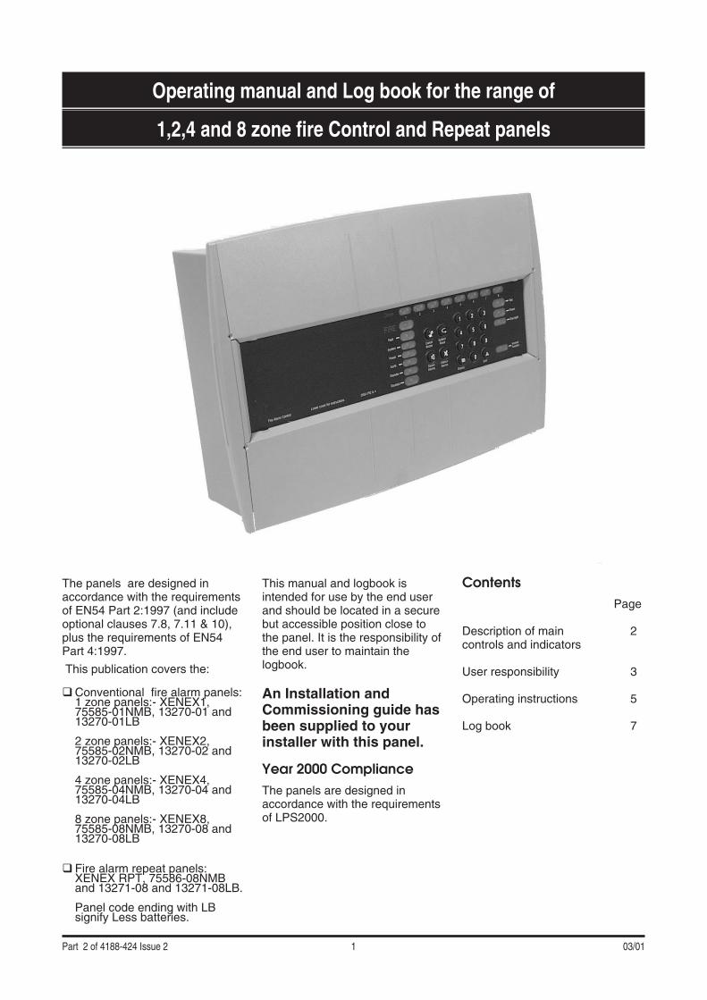
The panels are designed inaccordance with the requirementsof EN54 Part 2:1997 (and includeoptional clauses 7.8, 7.11 & 10),plus the requirements of EN54Part 4:1997.
This publication covers the:
�Conventional fire alarm panels:1 zone panels:- XENEX1,75585-01NMB, 13270-01 and13270-01LB
2 zone panels:- XENEX2,75585-02NMB, 13270-02 and13270-02LB
4 zone panels:- XENEX4,75585-04NMB, 13270-04 and13270-04LB
8 zone panels:- XENEX8,75585-08NMB, 13270-08 and13270-08LB
� Fire alarm repeat panels:XENEX RPT, 75586-08NMBand 13271-08 and 13271-08LB.
Panel code ending with LBsignify Less batteries.
This manual and logbook isintended for use by the end userand should be located in a securebut accessible position close tothe panel. It is the responsibility ofthe end user to maintain thelogbook.
An Installation andCommissioning guide hasbeen supplied to yourinstaller with this panel.
Year 2000 ComplianceThe panels are designed inaccordance with the requirementsof LPS2000.
ContentsPage
Description of main 2controls and indicators
User responsibility 3
Operating instructions 5
Log book 7
Part 2 of 4188-424 Issue 2 1 03/01
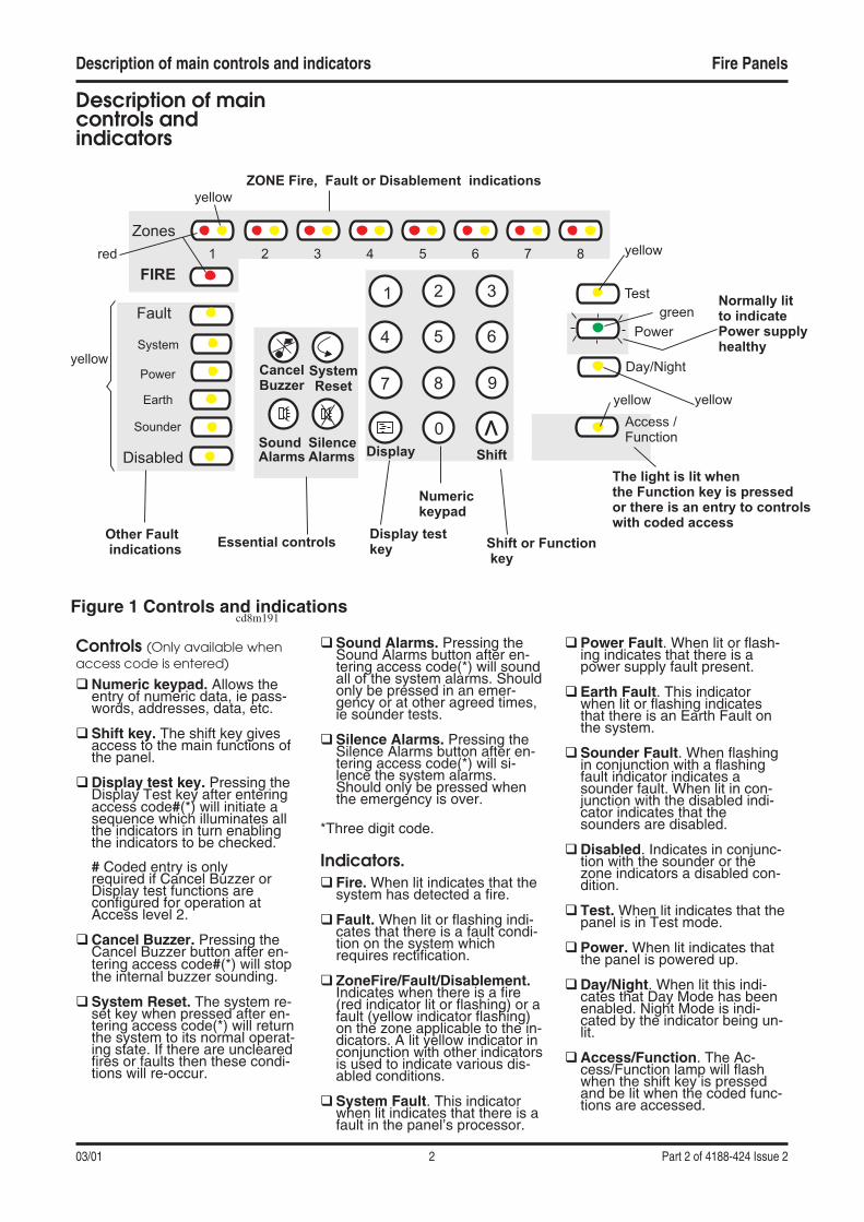
Description of maincontrols andindicators
Controls (Only available whenaccess code is entered)
�Numeric keypad. Allows theentry of numeric data, ie pass-words, addresses, data, etc.
�Shift key. The shift key givesaccess to the main functions ofthe panel.
�Display test key. Pressing theDisplay Test key after enteringaccess code#(*) will initiate asequence which illuminates allthe indicators in turn enablingthe indicators to be checked.
# Coded entry is onlyrequired if Cancel Buzzer orDisplay test functions areconfigured for operation atAccess level 2.
�Cancel Buzzer. Pressing theCancel Buzzer button after en-tering access code#(*) will stopthe internal buzzer sounding.
�System Reset. The system re-set key when pressed after en-tering access code(*) will returnthe system to its normal operat-ing state. If there are unclearedfires or faults then these condi-tions will re-occur.
�Sound Alarms. Pressing theSound Alarms button after en-tering access code(*) will soundall of the system alarms. Shouldonly be pressed in an emer-gency or at other agreed times,ie sounder tests.
�Silence Alarms. Pressing theSilence Alarms button after en-tering access code(*) will si-lence the system alarms.Should only be pressed whenthe emergency is over.
*Three digit code.
Indicators.� Fire. When lit indicates that the
system has detected a fire.
� Fault. When lit or flashing indi-cates that there is a fault condi-tion on the system whichrequires rectification.
� ZoneFire/Fault/Disablement.Indicates when there is a fire(red indicator lit or flashing) or afault (yellow indicator flashing)on the zone applicable to the in-dicators. A lit yellow indicator inconjunction with other indicatorsis used to indicate various dis-abled conditions.
�System Fault. This indicatorwhen lit indicates that there is afault in the panel’s processor.
�Power Fault. When lit or flash-ing indicates that there is apower supply fault present.
�Earth Fault. This indicatorwhen lit or flashing indicatesthat there is an Earth Fault onthe system.
�Sounder Fault. When flashingin conjunction with a flashingfault indicator indicates asounder fault. When lit in con-junction with the disabled indi-cator indicates that thesounders are disabled.
�Disabled. Indicates in conjunc-tion with the sounder or thezone indicators a disabled con-dition.
� Test. When lit indicates that thepanel is in Test mode.
�Power. When lit indicates thatthe panel is powered up.
�Day/Night. When lit this indi-cates that Day Mode has beenenabled. Night Mode is indi-cated by the indicator being un-lit.
�Access/Function. The Ac-cess/Function lamp will flashwhen the shift key is pressedand be lit when the coded func-tions are accessed.
Description of main controls and indicators Fire Panels
03/01 2 Part 2 of 4188-424 Issue 2
CancelBuzzer
SystemReset
SoundAlarms
SilenceAlarms
1 2 3
4 5 6
7 8 9
0v
Shift or Functionkey
Shift
Numerickeypad
Display testkey
Display
Essential controls
Zones
FIRE
Fault
System
Power
Earth
Sounder
Disabled
Test
Day/Night
Access /Function
Normally litto indicatePower supplyhealthy
The light is lit whenthe Function key is pressedor there is an entry to controlswith coded access
ZONE Fire, Fault or Disablement indications
Other Faultindications
1red
yellow
2 3 4 5 6 7
yellow
yellow
yellow
green
8
Power
yellow
Figure 1 Controls and indicationscd8m191

User ResponsibilityIt is recommended that thepersons responsible for the firealarm system, should becomefamiliar with the procedures onhow to operate the controls andinterpret indications given at thecontrol and repeat panels.Adequate training should alsohave been given from appointedpersonnel.
DailyThe British Standard code ofpractice for Fire detection andalarm systems for buildings,BS 5839:Part1:1988, states thatthe system should be inspecteddaily to ensure that a normalindication is given at the controland indicating equipment and thatany previously indicated faultcondition has received appropriateattention.
a) It recommends entry into theLog Book provided of all thesystem events for futurereference.
b) The person inspecting theprotected premises can ensurethat the use of the area(s)inspected has not changedsuch that the detection andalarm devices have becomeinappropriate.
c) The area(s) can be inspectedto check that no unsafepractices that could lead to fireare being undertaken.
WeeklyAt Weekly intervals a different Firedetector or Manual Call Point ofthe system should be tested toensure the system is capable ofoperating under alarm condition.
a) The operation of the alarmsounders should be checked,which also provides a regularreminder to those occupyingthe premises that there is a firealarm system with a particularcharacteristic sound.
b) The test should be performedat a regular time to avoidconfusion between a test and agenuine fire alarm.
QuarterlyAt quarterly intervals the systemshould be inspected and any worknecessary should be performed bya trained maintenance engineer.
Battery Replacement
NOTE: Any servicing work onthe System must be carried outby a servicing organisation.
Under normal operating conditionsthe maintenance free lead acidbatteries in the Control andRepeat panels can have a usefullife of up to 5 years from the dateof manufacture.
NOTE: It is recommended thatthese batteries are replaced at4 Yearly intervals from the datethe System is firstcommissioned.
CAUTION: The batteries shouldonly be replaced by trainedservice personal.
Fire Panels User Responsibility
Part 2 of 4188-424 Issue 2 3 03/01
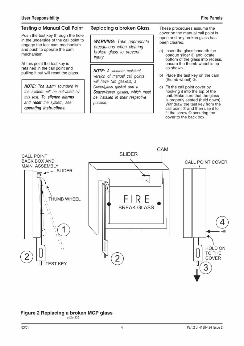
Testing a Manual Call PointPush the test key through the holein the underside of the call point toengage the test cam mechanismand push to operate the cammechanism.
At this point the test key isretained in the call point andpulling it out will reset the glass.
NOTE: The alarm sounders inthe system will be activated bythis test. To silence alarmsand reset the system, seeoperating instructions.
Replacing a broken Glass
WARNING: Take appropriateprecautions when clearingbroken glass to preventinjury.
NOTE: A weather resistantversion of manual call pointswill have two gaskets, aCover/glass gasket and aSpacer/cover gasket, which mustbe installed in their respectiveposition.
These procedures assume thecover on the manual call point isopen and any broken glass hasbeen cleared.
a) Insert the glass beneath theopaque slider � and locatebottom of the glass into recess,ensure the thumb wheel is upas shown..
b) Place the test key on the cam(thumb wheel) �.
c) Fit the call point cover byhooking it into the top of theunit. Make sure that the glassis properly seated (held down).Withdraw the test key from thecall point � and then use it tofit the screw � securing thecover to the back box.
User Responsibility Fire Panels
03/01 4 Part 2 of 4188-424 Issue 2
BREAK GLASS
F I R E
CAMSLIDER
3
4
CALL POINT COVER
THUMB WHEEL
SLIDER
1
2TEST KEY
CALL POINTBACK BOX ANDMAIN ASSEMBLY
2
HOLD ONTO THECOVER
Figure 2 Replacing a broken MCP glasscd8m322
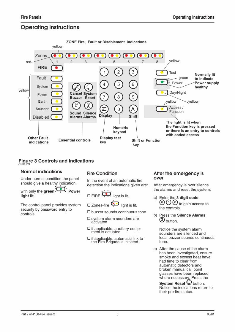
Operating instructions
Normal indicationsUnder normal condition the panelshould give a healthy indication,
with only the green Powerlight lit.
The control panel provides systemsecurity by password entry tocontrols.
Fire ConditionIn the event of an automatic firedetection the indications given are:
� FIRE light is lit.
� Zones-fire light is lit.
� buzzer sounds continuous tone.
� system alarm sounders areactivated
� if applicable, auxiliary equip-ment is actuated
� if applicable, automatic link tothe Fire Brigade is initiated.
After the emergency isoverAfter emergency is over silencethe alarms and reset the system:
a) Enter the 3 digit code
to gain access tothe controls.
b) Press the Silence Alarms
button.
Notice the system alarmsounders are silenced andlocal buzzer sounds continuoustone.
c) After the cause of the alarmhas been investigated, ensuresmoke and excess heat havehad time to clear fromautomatic detectors andbroken manual call pointglasses have been replacedwhere necessary. Press the
System Reset button.Notice the indications return totheir pre fire status.
Fire Panels Operating instructions
Part 2 of 4188-424 Issue 2 5 03/01
CancelBuzzer
SystemReset
SoundAlarms
SilenceAlarms
1 2 3
4 5 6
7 8 9
0v
Shift or Functionkey
Shift
Numerickeypad
Display testkey
Display
Essential controls
Zones
FIRE
Fault
System
Power
Earth
Sounder
Disabled
Test
Day/Night
Access /Function
Normally litto indicatePower supplyhealthy
The light is lit whenthe Function key is pressedor there is an entry to controlswith coded access
ZONE Fire, Fault or Disablement indications
Other Faultindications
1red
yellow
2 3 4 5 6 7
yellow
yellow
yellow
green
8
Power
yellow
Figure 3 Controls and indicationscd8m191
n n n

To Sound AlarmsTo re-sound the alarm soundersduring a fire condition:
a) Enter the 3 digit code
to gain access tothe controls.
b) Press the Sound Alarms
button.Notice the system alarmSounders are activated.
To Silence AlarmsTo silence system alarm soundersafter they have been actuated:
a) Enter the 3 digit code
to gain access tothe controls.
b) Press the Silence Alarmsbutton.Notice the system alarmSounders are silenced.
To carry out a display testa) #Enter the 3 digit code
to gain access tothe controls.# Coded entry is onlyrequired if Display test functionis configured for operation atAccess level 2.
b) Press the ‘shift‘ button and
then the display button.Ensure that all the LEDs light insequence and the buzzersounds.
Fault ConditionIn the event of an automatic faultdetection the indications given are:
� Fault light is lit
� fault indicators are lit
� buzzer sounds intermittent.(except for system fault which isa continuous sound)
To Cancel fault buzzera) #Enter the 3 digit code
to gain access tothe controls.
# Coded entry is onlyrequired if Cancel Buzzerfunction is configured foroperation at Access level 2.
b)b) After investigating fault, press
the Cancel Buzzerbutton. Notice the buzzer issilenced but other indicationsremain active.
The fault indications arenormally automaticallyextinguished once the faultcondition has been rectified.
Action to rectify faultSuggested action to rectify faultcondition:
NOTE: All fault rectification workmust be done by suitablyqualified personnel.
The fault indicators may beextinguished during a firecondition.
The mains failure conditionoverrides all other fault indicationsin order to preserve batterystandby capacity.
NOTE: A comprehensive faultfinding guide is included in theInstallation and Commissioningguide.
Operating instructions Fire Panels
03/01 6 Part 2 of 4188-424 Issue 2
vv
n n n
n n n
n n n
n n n
Visual indications Audibleindication
Signals out
Condition ZoneFire(1-8)-Red
FireCommon- Red
Disabled- Yellow
Test -Yellow
Power -Green
Access/Function- Yellow
Buzzer Soundercircuits
AuxRelaycontactsNormallyde-energised
Commonfault -Normallyactive
Common fire-Normallydeactive
Normalindication
On Normal Active Deactive
Fire On On On On On Changeover
Active Active
New fire(differentzone)
On On On On On Changeover
Active Active
AL2, 3 or 4 On On Normal Active Deactive
Functionkey press
On FastPulse
Normal Active Deactive
Indications on panel
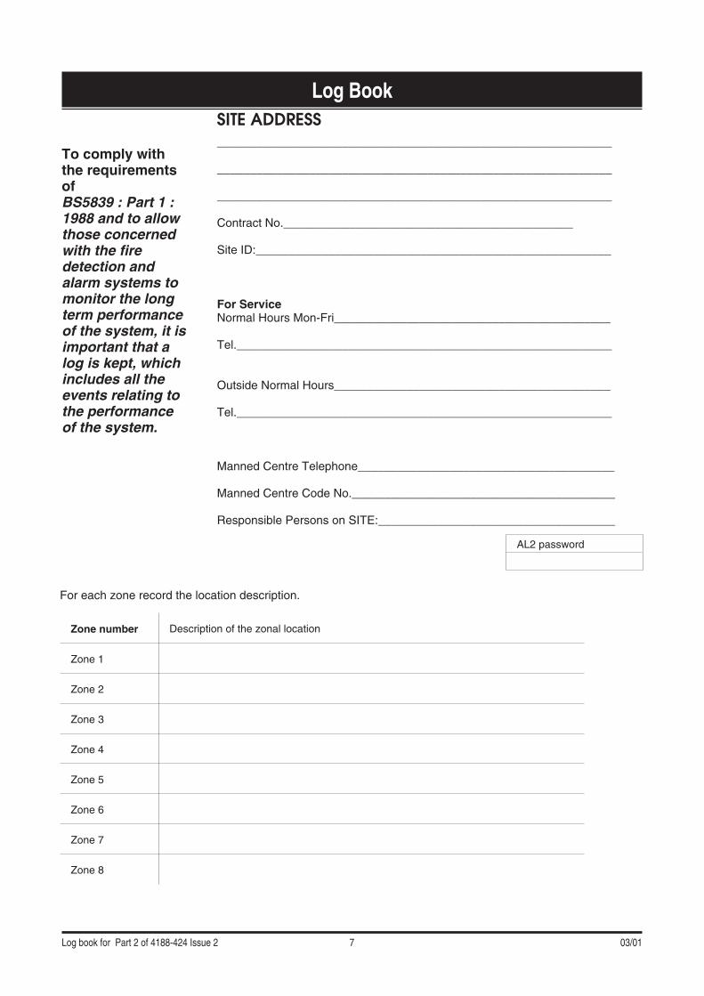
Log Book
To comply withthe requirementsofBS5839 : Part 1 :1988 and to allowthose concernedwith the firedetection andalarm systems tomonitor the longterm performanceof the system, it isimportant that alog is kept, whichincludes all theevents relating tothe performanceof the system.
Log book for Part 2 of 4188-424 Issue 2 7 03/01
SITE ADDRESS____________________________________________________________
____________________________________________________________
____________________________________________________________
Contract No.____________________________________________
Site ID:______________________________________________________
For ServiceNormal Hours Mon-Fri__________________________________________
Tel._________________________________________________________
Outside Normal Hours__________________________________________
Tel._________________________________________________________
Manned Centre Telephone_______________________________________
Manned Centre Code No.________________________________________
Responsible Persons on SITE:____________________________________
For each zone record the location description.
Zone number Description of the zonal location
Zone 1
Zone 2
Zone 3
Zone 4
Zone 5
Zone 6
Zone 7
Zone 8
AL2 password
Fire Panels
03/01 8 Log book for Part 2 of 4188-424 Issue 2
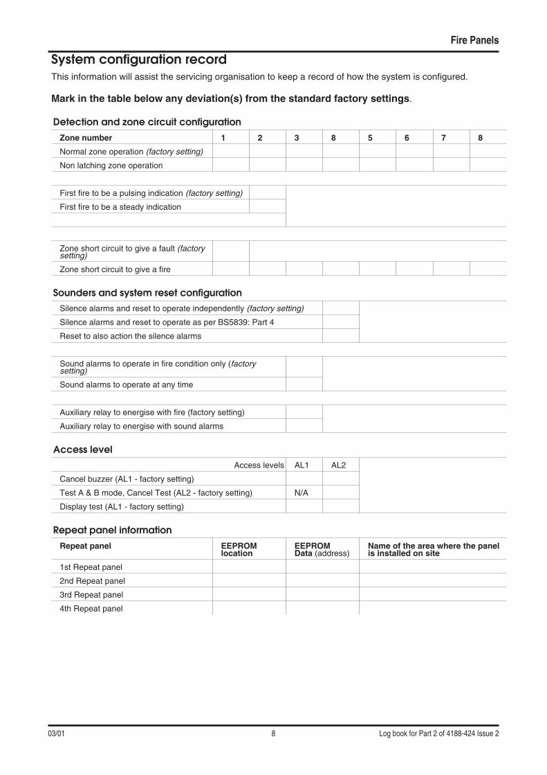
System configuration recordThis information will assist the servicing organisation to keep a record of how the system is configured.
Mark in the table below any deviation(s) from the standard factory settings.
Detection and zone circuit configurationZone number 1 2 3 8 5 6 7 8
Normal zone operation (factory setting)
Non latching zone operation
First fire to be a pulsing indication (factory setting)
First fire to be a steady indication
Zone short circuit to give a fault (factorysetting)
Zone short circuit to give a fire
Sounders and system reset configurationSilence alarms and reset to operate independently (factory setting)
Silence alarms and reset to operate as per BS5839: Part 4
Reset to also action the silence alarms
Sound alarms to operate in fire condition only (factorysetting)
Sound alarms to operate at any time
Auxiliary relay to energise with fire (factory setting)
Auxiliary relay to energise with sound alarms
Access levelAccess levels AL1 AL2
Cancel buzzer (AL1 - factory setting)
Test A & B mode, Cancel Test (AL2 - factory setting) N/A
Display test (AL1 - factory setting)
Repeat panel informationRepeat panel EEPROM
locationEEPROMData (address)
Name of the area where the panelis installed on site
1st Repeat panel
2nd Repeat panel
3rd Repeat panel
4th Repeat panel
Fire Panels Location of system devices
Log book for Part 2 of 4188-424 Issue 2 9 03/01
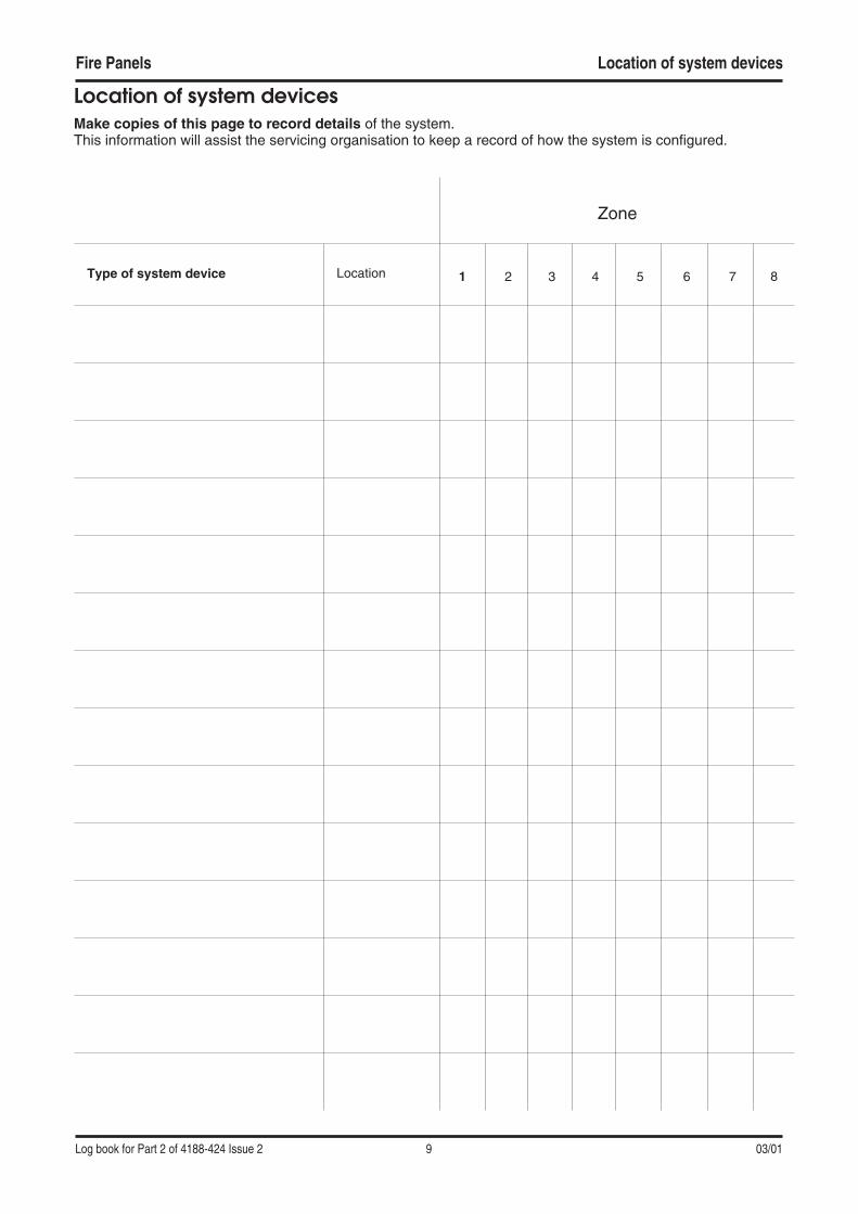
Location of system devicesMake copies of this page to record details of the system.This information will assist the servicing organisation to keep a record of how the system is configured.
Zone
Type of system device Location 1 2 3 4 5 6 7 8

Event log Fire Panels
03/01 10 Log book for Part 2 of 4188-424 Issue 2
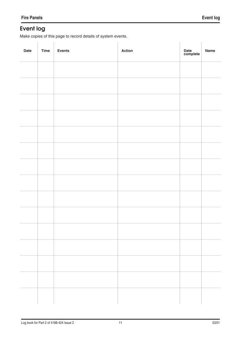
Event logMake copies of this page to record details of system events.
Date Time Events Action Datecomplete
Name
Fire Panels Event log
Log book for Part 2 of 4188-424 Issue 2 11 03/01
Event logMake copies of this page to record details of system events.
Date Time Events Action Datecomplete
Name

Event log Fire Panels
03/01 12 Log book for Part 2 of 4188-424 Issue 2