operating, maintenance, parts manual compressor … · 2019-07-09 · ingersoll--rand cannot...
TRANSCRIPT
Book 35393065 (7/02) 1( )
Code: A
This manual contains important safety information.Do not destroy this manual.This manual must be available to the personnel who operate and maintain this machine.
!
Portable Air Compressor DivisionP.O. Box 868 -- 501 Sanford AveMocksville, N.C. 27028
OPERATING, MAINTENANCE,PARTS MANUAL
COMPRESSOR MODELSP130WJDUP175WJDUP185WJDU
Book 35393065 (7/02) 2( )
QUALITY POLICYWe will supply products and services that consistently meet the requirementsof our customers and each other.
CALIFORNIA
Proposition 65 Warning
Diesel engine exhaust and some of its constituents are knownto the State of California to cause cancer, birth defects, andother reproductive harm.
Book 35393065 (7/02) 3( )
ForewordMachine models represented in this manual may be used in various locations worldwide. Machines sold and
shipped into European common market countries requires that the machine display the EC Mark and conform to
various directives. In such cases, the design specification of this machinehas been certified as complyingwithEC
directives. Anymodification to any part is absolutely prohibited andwould result in theCEcertification andmarking
being rendered invalid. A declaration of that conformity follows:
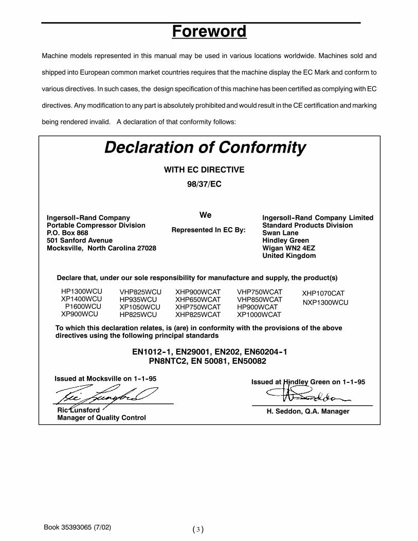
Declaration of ConformityWITH EC DIRECTIVE
WeIngersoll--Rand CompanyPortable Compressor DivisionP.O. Box 868501 Sanford AvenueMocksville, North Carolina 27028
Declare that, under our sole responsibility for manufacture and supply, the product(s)
To which this declaration relates, is (are) in conformity with the provisions of the abovedirectives using the following principal standards
________________________________
Represented In EC By:
Ingersoll--Rand Company LimitedStandard Products DivisionSwan LaneHindley GreenWigan WN2 4EZUnited Kingdom
Issued at Mocksville on 1--1--95 Issued at Hindley Green on 1--1--95
________________________________
EN1012--1, EN29001, EN202, EN60204--1PN8NTC2, EN 50081, EN50082
HP1300WCUXP1400WCUP1600WCUXP900WCU
XHP900WCATXHP650WCATXHP750WCATXHP825WCAT
VHP825WCUHP935WCUXP1050WCUHP825WCU
VHP750WCATVHP850WCATHP900WCATXP1000WCAT
98/37/EC
XHP1070CATNXP1300WCU
H. Seddon, Q.A. ManagerRic LunsfordManager of Quality Control
Book 35393065 (7/02) 4( )
Nothing contained in this document is intended to extend any promise, warranty or representation, expressed orimplied, regarding the Ingersoll--Rand products described herein. Any such warranties or other terms andconditions of sale of products shall be in accordance with the standard terms and conditions of sale for suchproducts, which are available upon request.
This manual contains instructions and technical data to cover all routine operation and scheduled maintenancetasks by operation and maintenance staff. Major overhauls are outside the scope of this manual and should bereferred to an authorized Ingersoll--Rand service department.
All components, accessories, pipes and connectors added to the compressed air system should be:
S of good quality, procured from a reputable manufacturer and, wherever possible, be of a typeapproved by Ingersoll--Rand.S clearly rated for a pressure at least equal to the machine maximum allowable working pressure.S compatible with the compressor lubricant/coolant.S accompanied with instructions for safe installation, operation and maintenance.
Details of approved equipment are available from Ingersoll--Rand Service departments.The use of repair parts other than those included within the Ingersoll--Rand approved parts list may createhazardous conditions over which Ingersoll--Rand has no control. Therefore, Ingersoll--Rand cannot be heldresponsible for equipment in which non--approved repair parts are installed.
Ingersoll--Rand reserves the right to make changes and improvements to products without notice and withoutincurring any obligation to make such changes or add such improvements to products sold previously.
The intendeduses of thismachineare outlinedbelowandexamples of unapprovedusagearealso given.However,Ingersoll--Rand cannot anticipate every application or work situation that may arise. If in doubt, consultsupervision.
This machine has been designed and supplied for above ground operation to be used for compression of normalambient air containing no additional gases, vapors or particles within the ambient temperature range specified inthe general data section of this manual.
This machine should not be used:
A. For direct or indirect human consumption of the compressed air.
B. Outside the ambient temperature range specified in the general data section of this manual.
C. When an actual or foreseeable risk of hazardous levels of flammable gases or vapors exists.
D. With other than Ingersoll--Rand approved components.
E. With guards, or controls or switches missing or disabled.
F. For storage or transportation of materials inside or on the enclosure.
This company accepts no responsibility for errors in translation of this manual from the original English version.
Book 35393065 (7/02) 5( )
TABLE OF CONTENTSSECTION 1 SAFETY. . . . . . . . . . . . . . .
SECTION 2 WARRANTY/REGISTRATION. . . . . . . . . . . . . . .
SECTION 3 NOISE EMISSION. . . . . . . . . . . . . . .
SECTION 4 GENERAL DATA. . . . . . . . . . . . . . .
SECTION 5 OPERATION. . . . . . . . . . . . . . .
SECTION 6 MAINTENANCE. . . . . . . . . . . . . . .
SECTION 7 LUBRICATION. . . . . . . . . . . . . . .
SECTION 8 TROUBLESHOOTING. . . . . . . . . . . . . . .
SECTION 9 PARTS ORDERING. . . . . . . . . . . . . . .
SECTION 10 PARTS LIST. . . . . . . . . . . . . .
SECTION 11 OPTIONS PARTS LIST. . . . . . . . . . . . . .
SECTION 12 ENGINE. . . . . . . . . . . . . .
Book 35393065 (7/02) 6( )
SECTION 1-- SAFETYSAFETY PRECAUTIONS
General Information
Ensure that the operator reads and understands the
decals and consults the manuals before maintenance
or operation.
Ensure that the Operation and Maintenance manual,
and the manual holder if equipped, are not removed
permanently from the machine.
Ensure that maintenance personnel are adequately
trained, competent and have read the manuals.
Make sure that all protective covers are in place and
that the canopy/doors are closed during operation.
The specification of this machine is such that the ma-
chine is not suitable for use in flammable gas risk
areas. If such an application is required then all local
regulations, codes of practice and site rules must be
observed. To ensure that the machine can operate in
a safe and reliablemanner, additional equipment such
as gas detection, exhaust spark arrestors, and intake
(shut--off) valves may be required, dependent on local
regulations or the degree of risk involved.
Air discharged from this machine may contain carbon
monoxide or other contaminants whichwill cause seri-
ous injury or death. Do not breathe this air.
Compressed air can be dangerous if incorrectly han-
dled. Before doing any work on the unit, ensure that all
pressure is vented from the system and that the ma-
chine cannot be started accidentally.
Ensure that themachine is operating at the ratedpres-
sure and that the rated pressure is known to all rele-
vant personnel.
All air pressure equipment installed in or connected to
the machine must have safe working pressure ratings
of at least the machine safety valve rating.
If more thanone compressor is connected to one com-
mon downstream plant, effective check valves and
isolation valves must be fitted and controlled by work
procedures, so that one machine cannot accidentally
be pressurized or over pressurized by another.
Compressed air must not be used for a feed to any
form of breathing apparatus or mask.
The discharged air contains a very small percentage
of compressor lubricating oil and care should be taken
to ensure that downstream equipment is compatible.
If the discharged air is to be ultimately released into a
confined space, adequate ventilation must be pro-
vided.
When using compressed air, always use appropriate
personal protective equipment.
All pressure containing parts, especially flexible hoses
and their couplings, must be regularly inspected, be
free from defects and be replaced according to the
Manual instructions.
Avoid bodily contact with compressed air.
The safety valve located in the separator tank must be
checked periodically for correct operation.
Never operate unit without first observing all safety
warnings and carefully reading the operation and
maintenance manual shipped from the factory with
this machine.
Never operate the engine of this machine inside abuilding without adequate ventilation. Avoid breathingexhaust fumes when working on or near the machine.Do not alter or modify this machine.
A battery contains sulfuric acid and can give off gaseswhich are corrosive and potentially explosive. Avoidcontact with skin, eyes and clothing. In case of con-tact, flush area immediately with water.
Book 35393065 (7/02) 7( )
Exercise extreme caution when using booster battery.To jump battery, connect ends of one booster cable tothe positive (+) terminal of each battery. Connect oneend of other cable to the negative (--) terminal of thebooster battery and other end to a ground connectionaway from dead battery (to avoid a spark occurringnear any explosive gases that may be present). Afterstarting unit, always disconnect cables in reverse or-der.
Never operate unit without first observing all safetywarnings and carefully reading the operation andmaintenance manual shipped from the factory withthis machine.
Thismachinemay include suchmaterials as oil, dieselfuel, antifreeze, brake fluid, oil/air filters and batterieswhich may require proper disposal when performingmaintenance and service tasks. Contact local authori-ties for proper disposal of these materials.
A battery contains sulfuric acid and can give off gaseswhich are corrosive and potentially explosive. Avoidcontact with skin, eyes and clothing. In case of con-tact, flush area immediately with water.
High Pressure Air can cause serious injury or death.Relieve pressure before removing filler plugs/caps, fit-tings or covers.
Air pressure can remain trapped in air supply linewhich can result in serious injury or death. Alwayscarefully vent air supply line at tool or vent valve beforeperforming any service.
Thismachineproduces loudnoisewith the doors openor service valve vented. Extended exposure to loudnoise can cause hearing loss. Always wear hearingprotection when doors are open or service valve isvented.
Never inspect or service unit without first disconnect-ing battery cable(s) to prevent accidental starting.
Do not remove the pressure cap from a HOT radiator.Allow radiator to cool down before removing pressurecap.
Do not use petroleum products (solvents or fuels) un-der high pressure as this can penetrate the skin andresult in serious illness. wear eye protection whilecleaning unit with compressed air to prevent debrisfrom injuring eye(s).
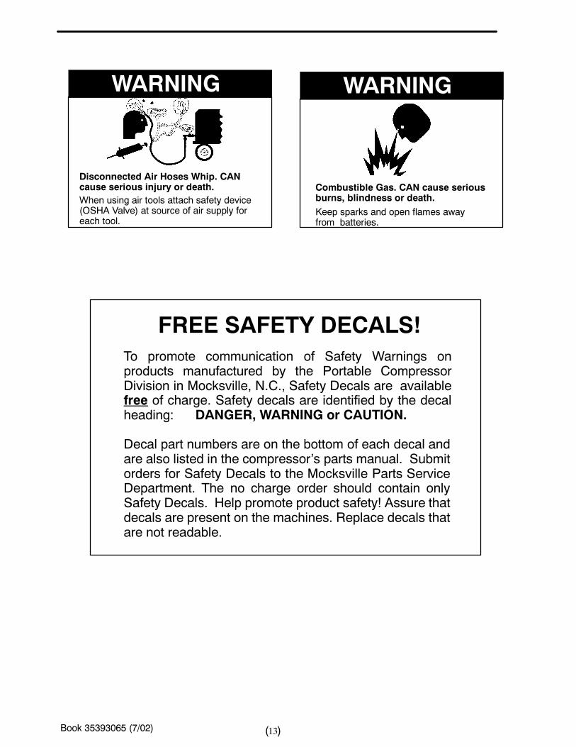
Disconnected air hoses whip and can cause seriousinjury or death. Always attach a safety flow restrictor
to each hose at the source of supply or branch line inaccordance with OSHA Regulation 29CFR Section1926.302(b).
Hot pressurized fluid can cause serious burns. Do notopen radiator while hot.
Rotating fan blade can cause serious injury. Do notoperate without guard in place.
Use care to avoid contacting hot surfaces (engineexhaust manifold and piping, air receiver and airdischarge piping, etc.).
Ether is an extremely volatile, highly flammable gas.USE SPARINGLY! Do NOT use ETHER if unit hasGLOW Plug starting aid. Engine damage will result.
Never allow the unit to sit stopped with pressure in thereceiver--separator system. As a precaution, open themanual blowdown valve.
Never operate unit with guards, covers or screensremoved. Keep hands, hair, clothing, tools, blow guntips, etc. well away from moving parts.
Make sure wheels, tires and tow bar connectors are insafe operating condition and tow bar is properlyconnected before towing.
Whenever the machine is stopped, air will flow backinto the compressor system from devices or systemsdownstream of the machine unless the service valveis closed. Install a check valve at the machine servicevalve to prevent reverse flow in the event of anunexpected shutdownwhen the service valve is open.
Hazardous Substance Precaution
The following substances are used in themanufactureof this machine and may be hazardous to health ifused incorrectly. Precaution: Avoid ingestion, skincontact and breathing fumes for the followingsubstances: Antifreeze, Compressor Oil, EngineLubricating Oil, Preservative Grease, RustPreventative, Diesel Fuel and Battery Electrolyte.
The following substancesmay be produced during theoperation of this machine and may be hazardous tohealth: Avoid build--up of Engine Exhaust Fumes inconfined spaces.
Avoid breathing Exhaust Fumes.
Avoid breathing Brake Lining Dust during mainte-nance.
Book 35393065 (7/02) 8( )
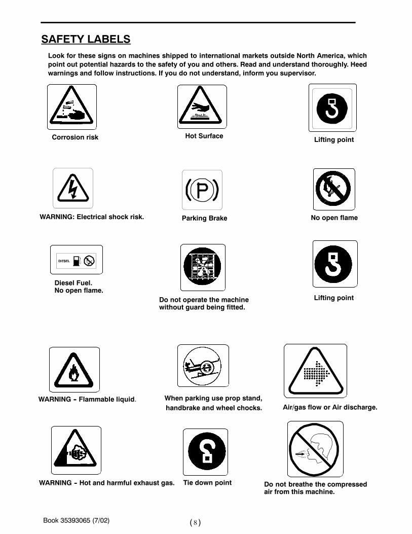
SAFETY LABELS
Corrosion risk
Do not operate the machinewithout guard being fitted.
Hot Surface
WARNING: Electrical shock risk.
Lifting point
Parking Brake No open flame
When parking use prop stand,
WARNING -- Hot and harmful exhaust gas.
WARNING -- Flammable liquid.Air/gas flow or Air discharge.
Look for these signs on machines shipped to international markets outside North America, whichpoint out potential hazards to the safety of you and others. Read and understand thoroughly. Heedwarnings and follow instructions. If you do not understand, inform you supervisor.
handbrake and wheel chocks.
Diesel Fuel.No open flame.
Do not breathe the compressedair from this machine.
Lifting point
Tie down point
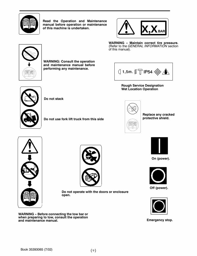
Book 35393065 (7/02) 9( )
Read the Operation and Maintenancemanual before operation or maintenanceof this machine is undertaken. X,XBAR
WARNING -- Maintain correct tire pressure.(Refer to the GENERAL INFORMATION sectionof this manual).
Rough Service DesignationWet Location Operation
WARNING: Consult the operationand maintenance manual beforeperforming any maintenance.
WARNING -- Before connecting the tow bar orwhen preparing to tow, consult the operationand maintenance manual.
Replace any crackedprotective shield.
On (power).
Off (power).
Emergency stop.
Do not use fork lift truck from this side
Do not stack
Do not operate with the doors or enclosureopen.
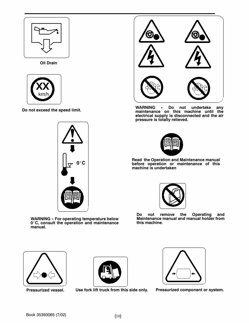
Book 35393065 (7/02) 10( )
Oil Drain
WARNING -- Do not undertake anymaintenance on this machine until theelectrical supply is disconnected and the airpressure is totally relieved.
Read the Operation and Maintenance manualbefore operation or maintenance of thismachine is undertaken
XXkm/h
Pressurized component or system.
Do not exceed the speed limit.
Pressurized vessel.
Do not remove the Operating andMaintenance manual and manual holder fromthis machine.
Use fork lift truck from this side only.
0_C
WARNING -- For operating temperature below0_C, consult the operation and maintenancemanual.
Book 35393065 (7/02) 11( )
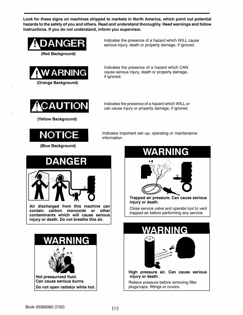
Indicates the presence of a hazard which WILL causeserious injury, death or property damage, if ignored.
Indicates the presence of a hazard which CANcause serious injury, death or property damage,if ignored.
Indicates the presence of a hazard which WILL orcan cause injury or property damage, if ignored.
Indicates important set--up, operating or maintenanceinformation.
(Orange Background)
(Yellow Background)
(Blue Background)
(Red Background)
!
!
Look for these signs on machines shipped to markets in North America, which point out potentialhazards to the safety of you and others. Read and understand thoroughly. Heed warnings and followinstructions. If you do not understand, inform you supervisor.
Air discharged from this machine cancontain carbon monoxide or othercontaminants which will cause seriousinjury or death. Do not breathe this air.
DANGER
Hot pressurized fluid.Can cause serious burns.Do not open radiator while hot.
WARNING
High pressure air. Can cause seriousinjury or death.
WARNING
WARNING
Trapped air pressure. Can cause seriousinjury or death.
Close service valve and operate tool to venttrapped air before performing any service.
Relieve pressure before removing fillerplugs/caps, fittings or covers.
Book 35393065 (7/02) 12( )
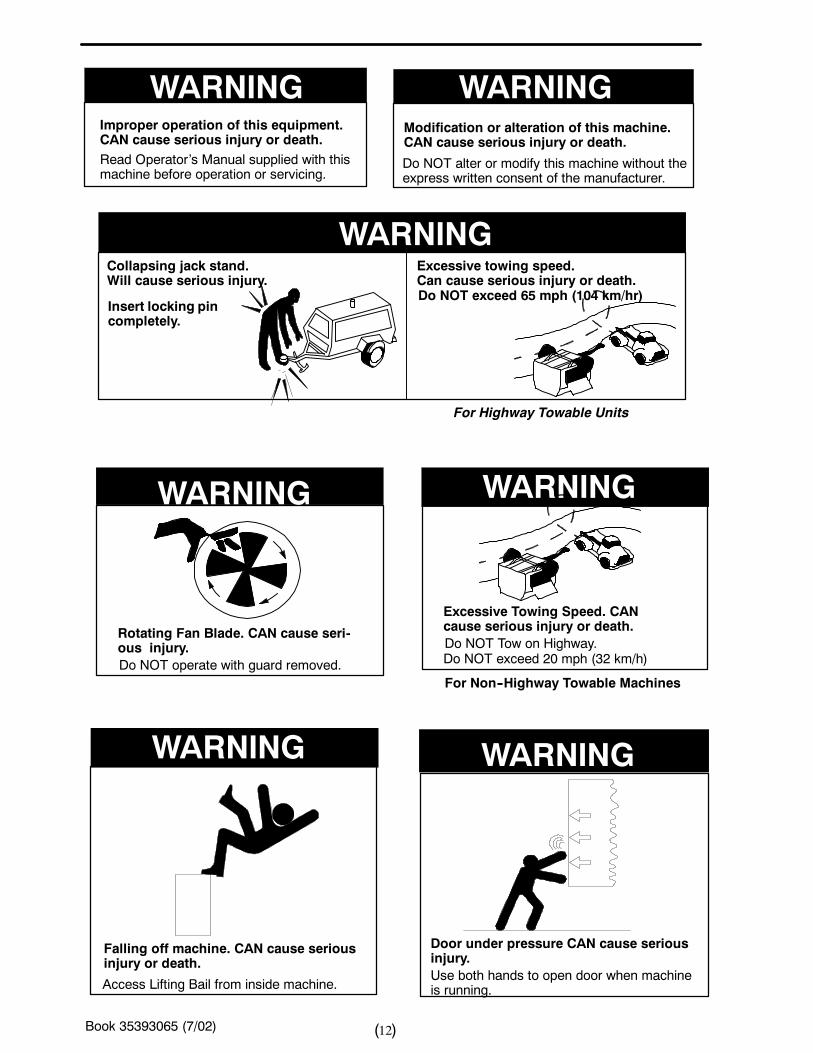
WARNINGCollapsing jack stand.Will cause serious injury.
Insert locking pincompletely.
Excessive towing speed.Can cause serious injury or death.Do NOT exceed 65 mph (104 km/hr)
For Highway Towable Units
WARNING WARNINGImproper operation of this equipment.CAN cause serious injury or death.Read Operator’s Manual supplied with thismachine before operation or servicing.
Modification or alteration of this machine.CAN cause serious injury or death.
Do NOT alter or modify this machine without theexpress written consent of the manufacturer.
WARNING
WARNING WARNING
WARNING
Falling off machine. CAN cause seriousinjury or death.
Access Lifting Bail from inside machine.
Rotating Fan Blade. CAN cause seri-ous injury.Do NOT operate with guard removed.
Excessive Towing Speed. CANcause serious injury or death.Do NOT Tow on Highway.Do NOT exceed 20 mph (32 km/h)
For Non--Highway Towable Machines
Door under pressure CAN cause seriousinjury.Use both hands to open door when machineis running.
Book 35393065 (7/02) 13( )
WARNING WARNING
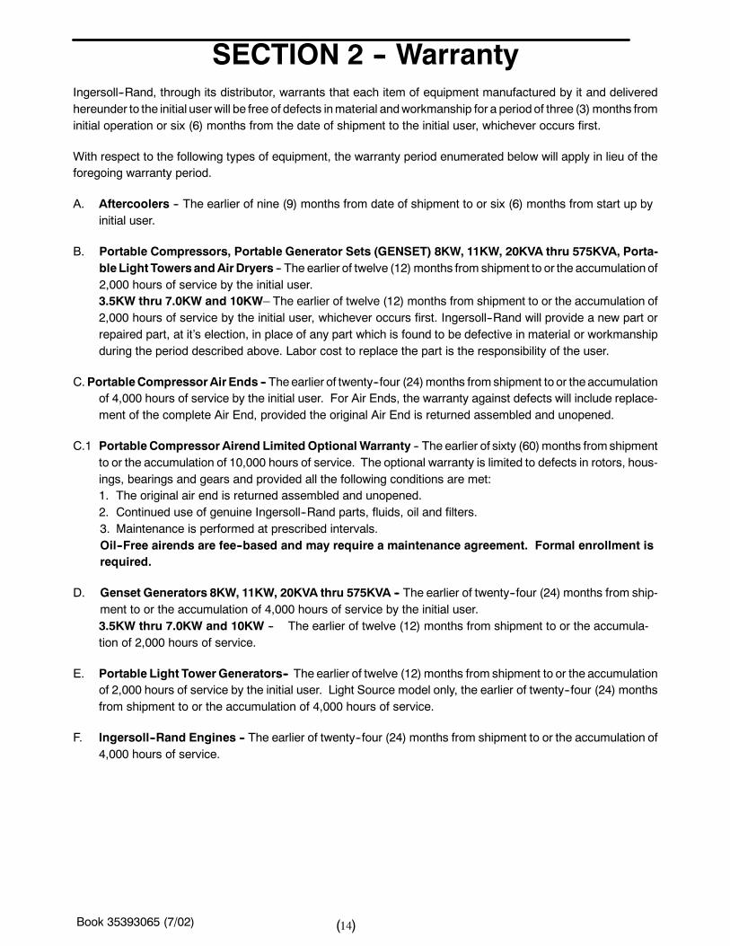
To promote communication of Safety Warnings onproducts manufactured by the Portable CompressorDivision in Mocksville, N.C., Safety Decals are availablefree of charge. Safety decals are identified by the decalheading: DANGER, WARNING or CAUTION.
Decal part numbers are on the bottom of each decal andare also listed in the compressor’s parts manual. Submitorders for Safety Decals to the Mocksville Parts ServiceDepartment. The no charge order should contain onlySafety Decals. Help promote product safety! Assure thatdecals are present on the machines. Replace decals thatare not readable.
FREE SAFETY DECALS!
Disconnected Air Hoses Whip. CANcause serious injury or death.When using air tools attach safety device(OSHA Valve) at source of air supply foreach tool.
Combustible Gas. CAN cause seriousburns, blindness or death.Keep sparks and open flames awayfrom batteries.
Book 35393065 (7/02) 14( )
SECTION 2 -- WarrantyIngersoll--Rand, through its distributor, warrants that each item of equipment manufactured by it and deliveredhereunder to the initial userwill be free of defects inmaterial andworkmanship for a periodof three (3) months frominitial operation or six (6) months from the date of shipment to the initial user, whichever occurs first.
With respect to the following types of equipment, the warranty period enumerated below will apply in lieu of theforegoing warranty period.
A. Aftercoolers -- The earlier of nine (9) months from date of shipment to or six (6) months from start up byinitial user.
B. Portable Compressors, Portable Generator Sets (GENSET) 8KW, 11KW, 20KVA thru 575KVA, Porta-bleLight TowersandAirDryers -- The earlier of twelve (12) months from shipment to or the accumulation of2,000 hours of service by the initial user.3.5KW thru 7.0KW and 10KW– The earlier of twelve (12) months from shipment to or the accumulation of2,000 hours of service by the initial user, whichever occurs first. Ingersoll--Rand will provide a new part orrepaired part, at it’s election, in place of any part which is found to be defective in material or workmanshipduring the period described above. Labor cost to replace the part is the responsibility of the user.
C.PortableCompressorAirEnds -- Theearlier of twenty--four (24)months fromshipment to or theaccumulationof 4,000 hours of service by the initial user. For Air Ends, the warranty against defects will include replace-ment of the complete Air End, provided the original Air End is returned assembled and unopened.
C.1 Portable Compressor Airend Limited OptionalWarranty -- The earlier of sixty (60)months fromshipmentto or the accumulation of 10,000 hours of service. The optional warranty is limited to defects in rotors, hous-ings, bearings and gears and provided all the following conditions are met:1. The original air end is returned assembled and unopened.2. Continued use of genuine Ingersoll--Rand parts, fluids, oil and filters.3. Maintenance is performed at prescribed intervals.Oil--Free airends are fee--based and may require a maintenance agreement. Formal enrollment isrequired.
D. Genset Generators 8KW, 11KW, 20KVA thru 575KVA -- The earlier of twenty--four (24) months from ship-ment to or the accumulation of 4,000 hours of service by the initial user.3.5KW thru 7.0KW and 10KW -- The earlier of twelve (12) months from shipment to or the accumula-tion of 2,000 hours of service.
E. Portable Light TowerGenerators-- The earlier of twelve (12) months from shipment to or the accumulationof 2,000 hours of service by the initial user. Light Source model only, the earlier of twenty--four (24) monthsfrom shipment to or the accumulation of 4,000 hours of service.
F. Ingersoll--Rand Engines -- The earlier of twenty--four (24) months from shipment to or the accumulation of4,000 hours of service.
Book 35393065 (7/02) 15( )
G. Ingersoll--Rand PlatinumDrive TrainWarranty (Optional) –Platinum drive train pertains to the Ingersoll--RandEngine andAirend combination. The earlier of sixty (60) months from shipment to, or the accumulationof 10,000 hours of service. The starter, alternator, fuel injection system and all electrical components areexcluded from the extendedwarranty. The airend seal and drive coupling are included in thewarranty (airenddrive belts are not included). The optional warranty is automatically available when meeting the followingconditions:
1. The original airend is returned assembled and unopened.2. Continued use of genuine Ingersoll--Rand parts, fluids, oil and filters.3. Maintenance is performed at prescribed intervals.
It is the obligation of the user to provide verification that these conditions have beensatisfied whensubmittingwarranty claims.
F. Spare Parts– Six (6) months from date of shipment.
Ingersoll--Randwill provide a new part or repaired part, at its election, in place of any part which is found uponits inspection to be defective in material and workmanship during the period prescribed above. Such part willbe repaired or replacedwithout charge to the initial user during normal working hours at the place of businessof an Ingersoll--Rand distributor authorized to sell the type of equipment involved or other establishment au-thorized by Ingersoll--Rand. User must present proof of purchase at the time of exercising warranty.
The abovewarrantees do not apply to failures occurring as a result of abuse; misuse, negligent repairs, corrosion,erosionandnormalwear and tear, alterations ormodificationsmade to theproduct without expresswritten consentof Ingersoll--Rand; or failure to follow the recommended operating practices andmaintenance procedures as pro-vided in the product’s operating and maintenance publications.
Accessories or equipment furnished by Ingersoll--Rand, but manufactured by others, including, but not limited to,engines, tires, batteries, engine electrical equipment, hydraulic transmissions, carriers, shall carry whatever war-ranty the manufacturers have conveyed to Ingersoll--Rand and which can be passed on to the initial user.
THISWARRANTY IS IN LIEUOF ALL OTHERWARRANTIES EXPRESSEDOR IMPLIED, (EXCEPT THAT OFTITLE),AND THERE ARE NOWARRANTIES OFMERCHANTABILITY OROF FITNESS FOR A PARTICULARPURPOSE.
Book 35393065 (7/02) 16( )
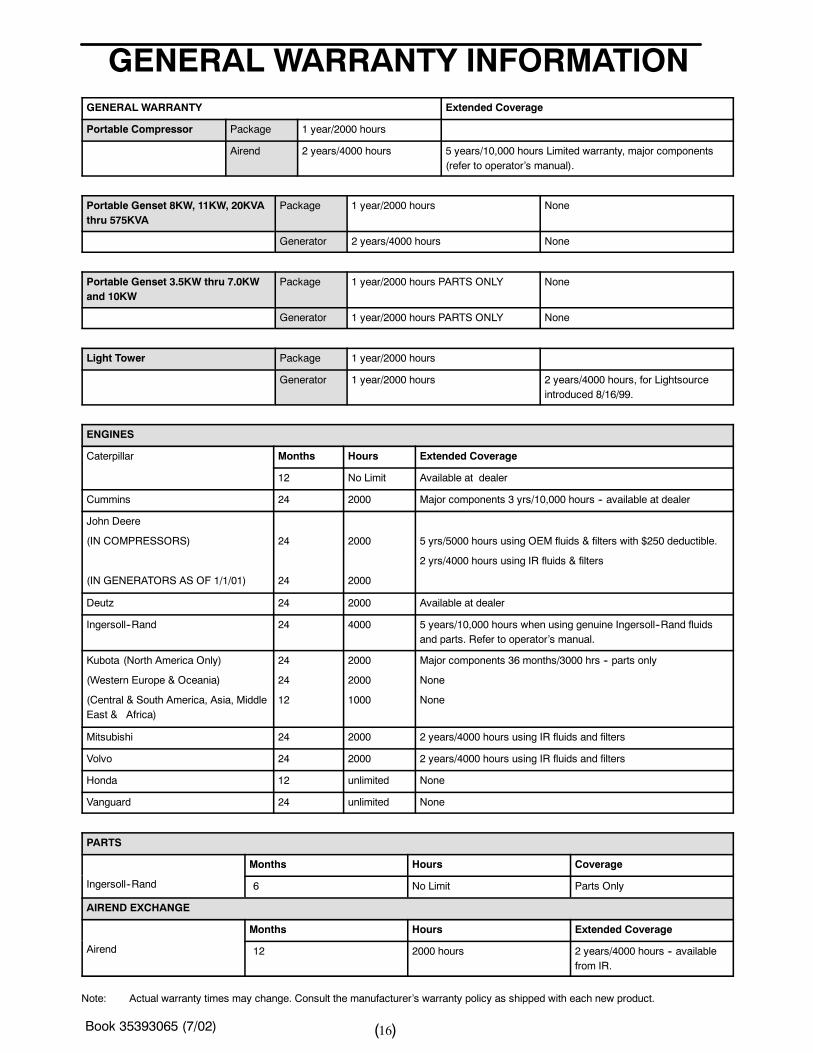
GENERAL WARRANTY INFORMATIONGENERAL WARRANTY Extended Coverage
Portable Compressor Package 1 year/2000 hours
Airend 2 years/4000 hours 5 years/10,000 hours Limited warranty, major components(refer to operator’s manual).
Portable Genset 8KW, 11KW, 20KVAthru 575KVA
Package 1 year/2000 hours None
Generator 2 years/4000 hours None
Portable Genset 3.5KW thru 7.0KWand 10KW
Package 1 year/2000 hours PARTS ONLY None
Generator 1 year/2000 hours PARTS ONLY None
Light Tower Package 1 year/2000 hours
Generator 1 year/2000 hours 2 years/4000 hours, for Lightsourceintroduced 8/16/99.
ENGINES
Caterpillar Months Hours Extended Coverage
12 No Limit Available at dealer
Cummins 24 2000 Major components 3 yrs/10,000 hours -- available at dealer
John Deere
(IN COMPRESSORS)
(IN GENERATORS AS OF 1/1/01)
24
24
2000
2000
5 yrs/5000 hours using OEM fluids & filters with $250 deductible.
2 yrs/4000 hours using IR fluids & filters
Deutz 24 2000 Available at dealer
Ingersoll--Rand 24 4000 5 years/10,000 hours when using genuine Ingersoll--Rand fluidsand parts. Refer to operator’s manual.
Kubota (North America Only)
(Western Europe & Oceania)
(Central & South America, Asia, MiddleEast & Africa)
24
24
12
2000
2000
1000
Major components 36 months/3000 hrs -- parts only
None
None
Mitsubishi 24 2000 2 years/4000 hours using IR fluids and filters
Volvo 24 2000 2 years/4000 hours using IR fluids and filters
Honda 12 unlimited None
Vanguard 24 unlimited None
PARTS
Months Hours Coverage
Ingersoll--Rand 6 No Limit Parts Only
AIREND EXCHANGE
Months Hours Extended Coverage
Airend 12 2000 hours 2 years/4000 hours -- availablefrom IR.
Note: Actual warranty times may change. Consult the manufacturer’s warranty policy as shipped with each new product.
Book 35393065 (7/02) 17( )
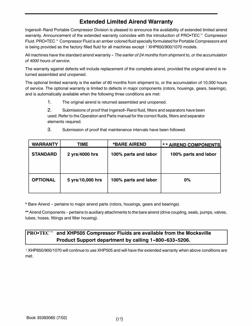
Extended Limited Airend WarrantyIngersoll--Rand Portable Compressor Division is pleased to announce the availability of extended limited airendwarranty. Announcement of the extended warranty coincides with the introduction of PROSTECt CompressorFluid. PROSTECtCompressor Fluid is an amber colored fluid specially formulated for Portable Compressors andis being provided as the factory filled fluid for all machines except ! XHP650/900/1070 models.
All machines have the standard airend warranty -- The earlier of 24 months from shipment to, or the accumulationof 4000 hours of service.
The warranty against defects will include replacement of the complete airend, provided the original airend is re-turned assembled and unopened.
The optional limited warranty is the earlier of 60 months from shipment to, or the accumulation of 10,000 hoursof service. The optional warranty is limited to defects in major components (rotors, housings, gears, bearings),and is automatically available when the following three conditions are met:
1. The original airend is returned assembled and unopened.
2. Submissions of proof that Ingersoll--Rand fluid, filters and separators have beenused. Refer to theOperation andParts manual for the correct fluids, filters and separatorelements required.
3. Submission of proof that maintenance intervals have been followed.
STANDARD
OPTIONAL
2 yrs/4000 hrs 100% parts and labor
WARRANTY TIME *BARE AIREND * * AIREND COMPONENTS
5 yrs/10,000 hrs
100% parts and labor
100% parts and labor 0%
* Bare Airend -- pertains to major airend parts (rotors, housings, gears and bearings).
** AirendComponents -- pertains to auxiliary attachments to the bare airend (drive coupling, seals, pumps, valves,tubes, hoses, fittings and filter housing).
PROSTECt and XHP505 Compressor Fluids are available from the MocksvilleProduct Support department by calling 1--800--633--5206.
! XHP650/900/1070 will continue to use XHP505 and will have the extended warranty when above conditions aremet.
Book 35393065 (7/02) 18( )
WARRANTY REGISTRATION
Complete Machine Registration
Machines shipped to locations within the United States do not require a warranty registrationunless the machine status changes (i.e. change of ownership).
Machines shipped outside the United States require notification be made to initiate themachine warranty.
Fill out theWarranty Registration Form in this section, keep a copy for your records andmail form to:
Ingersoll--Rand CompanyPortable Compressor Division
P.O. Box 868Mocksville, North Carolina 27028
Attn: Warranty Department
Note: Completion of this form validates the warranty.
Book 35393065 (7/02) 19( )
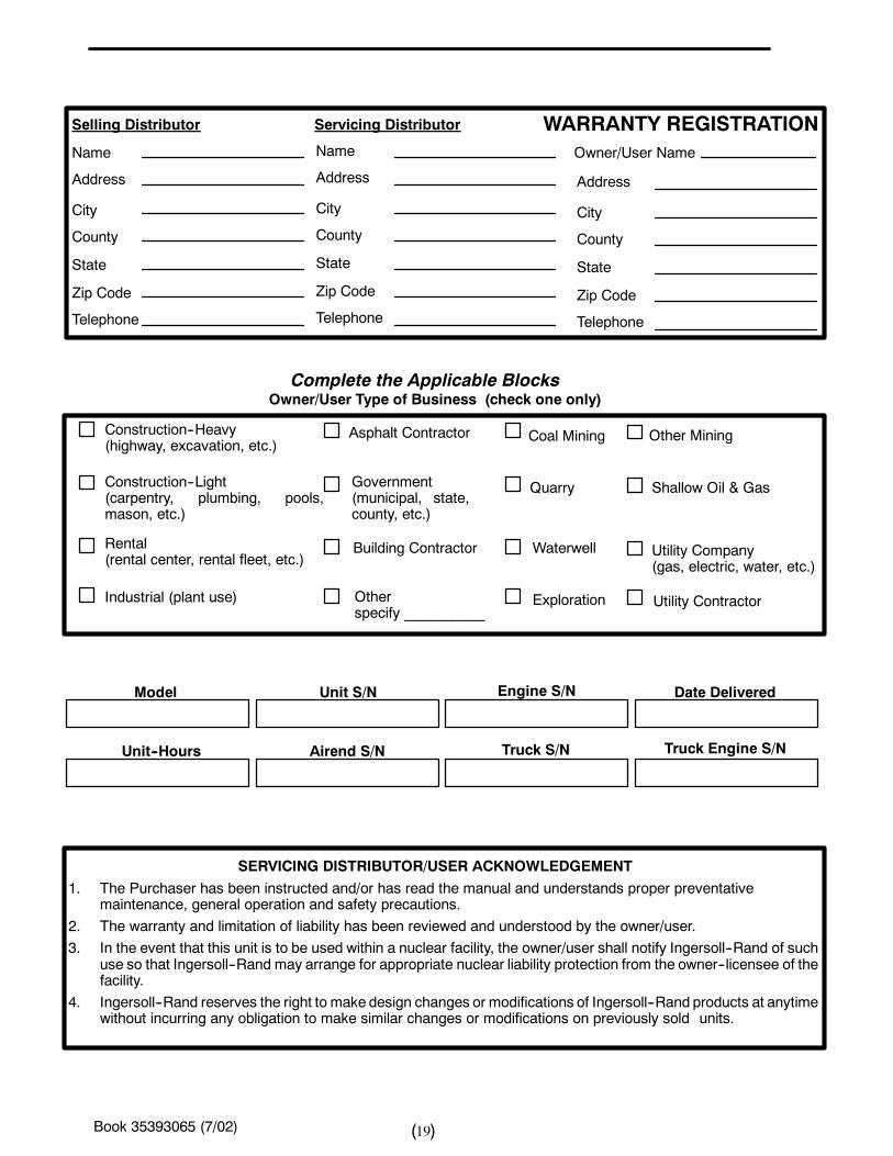
Selling Distributor Servicing Distributor WARRANTY REGISTRATIONName
Address
City
County
State
Zip Code
Telephone
Name
Address
City
County
State
Zip Code
Telephone
Address
City
County
State
Zip Code
Telephone
Owner/User Name
Complete the Applicable BlocksOwner/User Type of Business (check one only)
Construction--Heavy(highway, excavation, etc.)
Construction--Light(carpentry, plumbing, pools,mason, etc.)
Rental(rental center, rental fleet, etc.)
Industrial (plant use)
Asphalt Contractor
Government(municipal, state,county, etc.)
Building Contractor
Otherspecify __________
Coal Mining
Quarry
Waterwell
Exploration
Other Mining
Shallow Oil & Gas
Utility Company(gas, electric, water, etc.)
Utility Contractor
SERVICING DISTRIBUTOR/USER ACKNOWLEDGEMENT
1. The Purchaser has been instructed and/or has read the manual and understands proper preventativemaintenance, general operation and safety precautions.
2. The warranty and limitation of liability has been reviewed and understood by the owner/user.
3. In the event that this unit is to be used within a nuclear facility, the owner/user shall notify Ingersoll--Rand of suchuse so that Ingersoll--Rand may arrange for appropriate nuclear liability protection from the owner--licensee of thefacility.
4. Ingersoll--Rand reserves the right to make design changes or modifications of Ingersoll--Rand products at anytimewithout incurring any obligation to make similar changes or modifications on previously sold units.
Model Unit S/N Engine S/N Date Delivered
Unit--Hours Airend S/N Truck S/N Truck Engine S/N
Book 35393065 (7/02) 20( )
Ingersoll-RandCompanyPortableCompressorDivisionP.O.Box868Mocksville,NorthCarolina27028
Attention:WarrantyDepartment
fold
-- -- -- -- -- -- -- -- -- -- -- -- -- -- -- -- -- -- -- -- -- -- -- -- -- -- -- -- -- -- -- -- -- -- -- -- -- --
Book 35393065 (7/02) 21( )
SECTION 3 -- NOISE EMISSION
This section pertains only to machines distributed
within the United States.
WARNING
TAMPERING WITH NOISE CONTROL SYSTEM PROHIBITED
Federal law prohibits the following acts or the causing thereof:
(1) The removal or rendering inoperative by any persons, other than for purposes of maintenance, repair, or re-placement, of any device or element of design incorporated into any new compressor for the purpose of noisecontrol prior to its sale or delivery to the ultimate purchaser or while it is in use; or (2) the use of the compressorafter such device or element of design has been removed or rendered inoperative by any person.
Among those acts included in the prohibition against tampering are these:
4. Removal or rendering inoperative any of the following:
a. the engine exhaust system or parts thereof
b. the air intake system or parts thereof
c. enclosure or parts thereof
5. Removal of any of the following:
a. fan shroud
b. vibration mounts
c. sound absorption material
6. Operation of the compressor with any of the enclosure doors open.
Compressor Noise Emission Control InformationA. The removal or rendering inoperative, other than for the purpose of maintenance, repair, or replacement of anynoise control device or element of design incorporated into this compressor in compliance with the noise controlact;
B. The use of this compressor after such device or element of design has been removed or rendered inoperative.
Note: the above information applies only to units that arebuilt in compliancewith theU.S. EnvironmentalProtection Agency.
Ingersoll--Rand Company reserves the right to make changes or add improvements without notice and withoutincurring any obligation to make such changes or add such improvements to products sold previously.
The Purchaser is urged to include the above provisions in any agreement for any resale of this compressor.
Book 35393065 (7/02) 22( )
NOISE EMISSION CONTROLMAINTENANCE LOG
COMPRESSOR MODEL
SERIAL NO.
USER UNIT NO.
UNIT IDENTIFICATIONEngine Make & Model:
Serial No.:
Purchaser or Owner:
Address:
DEALER OR DISTRIBUTOR FROMWHOM PURCHASED:
Date Purchased:
TheNoiseControl Act of 1972 (86 Stat. 1234) prohibits tamperingwith the noise control systemof any compressormanufactured and sold under the above regulations, specifically the following acts or the causing thereof:
(1) the removal or rendering inoperative by any persons, other than for purposes of maintenance, repair, or re-placement, of any device or element of design incorporated into new compressor for the purpose of noise controlprior to its sale or delivery to the ultimate purchaser or while it is in use; or (2) the use of the compressor after suchdevice or element of design has been removed or rendered inoperative by any person.
NOISE EMISSION WARRANTY
Themanufacturerwarrants to theultimate purchaser andeach subsequent purchaser that this air compressorwasdesigned, built and equipped to conform at the time of sale to the first retail purchaser, with all applicable U.S. EPANoise Control Regulations.
This warranty is not limited to any particular part, component, or system of the air compressor. Defects in the de-sign, assembly or in any part, component, or system of the compressor which, at the time of sale to the first retailpurchaser, caused noise emissions to exceed Federal Standards are covered by this warranty for the life of theair compressor.
INTRODUCTIONThe unit for which this Maintenance Log is provided conforms to U.S. E.P.A. Regulations for Noise Emissions,applicable to Portable Air Compressors.
The purpose of this book is to provide (1) the Maintenance Performance Schedule for all required noise emissioncontrols and (2) space so that the purchaser or owner can record what maintenance was done, by whom, whereand when. The Maintenance Schedule and detailed instructions on the maintenance items are given on followingpage.
Book 35393065 (7/02) 23( )
MAINTENANCE SCHEDULE
ITEM AREA PERIODA.
B.
C.
D.
E.
F.
G.
H.
I.
J.
Compressed Air Leaks
Safety and Control Systems
Acoustic Materials
Fasteners
Enclosure Panels
Air Intake & Engine Exhaust
Cooling Systems
Isolation Mounts
Engine Operation
Fuels & Lubricants
As Detected
As Detected
Daily
100 hours
100 hours
100 hours
250 hours
250 hours
See Operator’s Manual
See Operator’s Manual
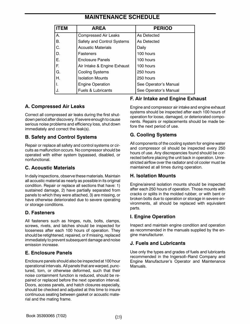
A. Compressed Air Leaks
Correct all compressed air leaks during the first shut-downperiodafter discovery. If severeenough tocauseserious noise problems and efficiency loss, shut downimmediately and correct the leak(s).
B. Safety and Control Systems
Repair or replace all safety and control systems or cir-cuits asmalfunction occurs. No compressor should beoperated with either system bypassed, disabled, ornonfunctional.
C. Acoustic Materials
In daily inspections, observe thesematerials.Maintainall acoustic material as nearly as possible in its originalcondition. Repair or replace all sections that have: 1)sustained damage, 2) have partially separated frompanels to which they were attached, 3) are missing, orhave otherwise deteriorated due to severe operatingor storage conditions.
D. Fasteners
All fasteners such as hinges, nuts, bolts, clamps,screws, rivets, and latches should be inspected forlooseness after each 100 hours of operation. Theyshould be retightened, repaired, or if missing, replacedimmediately to prevent subsequent damageandnoiseemission increase.
E. Enclosure Panels
Enclosure panels should also be inspectedat 100houroperational intervals. All panels that arewarped, punc-tured, torn, or otherwise deformed, such that theirnoise containment function is reduced, should be re-paired or replaced before the next operation interval.Doors, access panels, and hatch closures especially,should be checked and adjusted at this time to insurecontinuous seating between gasket or acoustic mate-rial and the mating frame.
F. Air Intake and Engine Exhaust
Engine and compressor air intake and engine exhaustsystems should be inspected after each 100 hours ofoperation for loose, damaged, or deteriorated compo-nents. Repairs or replacements should be made be-fore the next period of use.
G. Cooling Systems
All components of the cooling system for enginewaterand compressor oil should be inspected every 250hours of use. Any discrepancies found should be cor-rected before placing the unit back in operation. Unre-stricted airflow over the radiator and oil cooler must bemaintained at all times during operation.
H. Isolation Mounts
Engine/airend isolation mounts should be inspectedafter each 250 hours of operation. Those mounts withcracks or splits in the molded rubber, or with bent orbroken bolts due to operation or storage in severe en-vironments, all should be replaced with equivalentparts.
I. Engine Operation
Inspect and maintain engine condition and operationas recommended in the manuals supplied by the en-gine manufacturer.
J. Fuels and Lubricants
Use only the types and grades of fuels and lubricantsrecommended in the Ingersoll--Rand Company andEngine Manufacturer’s Operator and MaintenanceManuals.
Book 35393065 (7/02) 24( )
MAINTENANCE RECORD FOR NOISE EMISSION CONTROL AND EXTENDED WARRANTY
ITEM NO. DESCRIPTION OF WORK HOURMETERREADING
MAINT/
INSPECT DATE
LOCATION CITY/STATE
WORK DONE BY(NAME)
Book 35393065 (7/02) 25( )
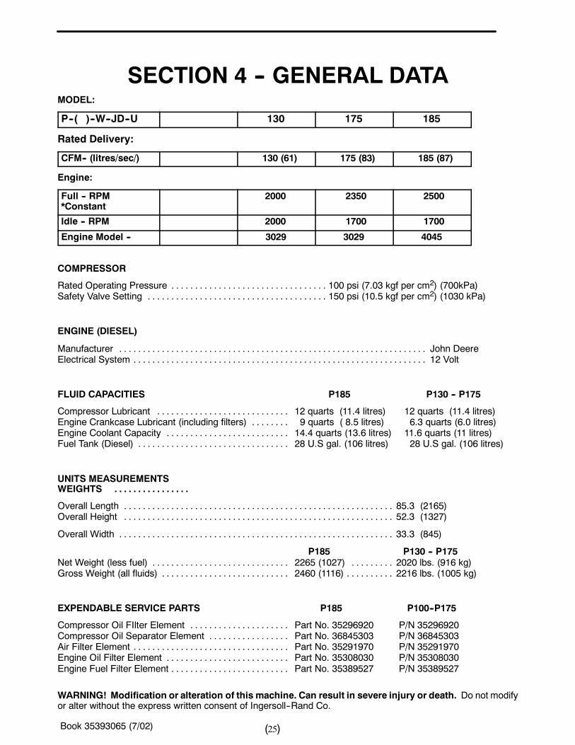
SECTION 4 -- GENERAL DATAMODEL:
P--( )--W--JD--U 130 175 185
Rated Delivery:
CFM-- (litres/sec/) 130 (61) 175 (83) 185 (87)
Engine:
Full -- RPM*Constant
2000 2350 2500
Idle -- RPM 2000 1700 1700
Engine Model -- 3029 3029 4045
COMPRESSOR
Rated Operating Pressure 100 psi (7.03 kgf per cm2) (700kPa). . . . . . . . . . . . . . . . . . . . . . . . . . . . . . . . .Safety Valve Setting 150 psi (10.5 kgf per cm2) (1030 kPa). . . . . . . . . . . . . . . . . . . . . . . . . . . . . . . . . . . . . .
ENGINE (DIESEL)
Manufacturer John Deere. . . . . . . . . . . . . . . . . . . . . . . . . . . . . . . . . . . . . . . . . . . . . . . . . . . . . . . . . . . . . . . . .Electrical System 12 Volt. . . . . . . . . . . . . . . . . . . . . . . . . . . . . . . . . . . . . . . . . . . . . . . . . . . . . . . . . . . . . .
FLUID CAPACITIES P185 P130 -- P175
Compressor Lubricant 12 quarts (11.4 litres) 12 quarts (11.4 litres). . . . . . . . . . . . . . . . . . . . . . . . . . . .Engine Crankcase Lubricant (including filters) 9 quarts ( 8.5 litres) 6.3 quarts (6.0 litres). . . . . . . .Engine Coolant Capacity 14.4 quarts (13.6 litres) 11.6 quarts (11 litres). . . . . . . . . . . . . . . . . . . . . . . . . .Fuel Tank (Diesel) 28 U.S gal. (106 litres) 28 U.S gal. (106 litres). . . . . . . . . . . . . . . . . . . . . . . . . . . . . . . .
UNITS MEASUREMENTSWEIGHTS . . . . . . . . . . . . . . . .
Overall Length 85.3 (2165). . . . . . . . . . . . . . . . . . . . . . . . . . . . . . . . . . . . . . . . . . . . . . . . . . . . . . . . .Overall Height 52.3 (1327). . . . . . . . . . . . . . . . . . . . . . . . . . . . . . . . . . . . . . . . . . . . . . . . . . . . . . . . .
Overall Width 33.3 (845). . . . . . . . . . . . . . . . . . . . . . . . . . . . . . . . . . . . . . . . . . . . . . . . . . . . . . . . . .
P185 P130 -- P175Net Weight (less fuel) 2265 (1027) 2020 lbs. (916 kg). . . . . . . . . . . . . . . . . . . . . . . . . . . . . . . . . . . . . .Gross Weight (all fluids) 2460 (1116) 2216 lbs. (1005 kg). . . . . . . . . . . . . . . . . . . . . . . . . . . . . . . . . . . . .
EXPENDABLE SERVICE PARTS P185 P100--P175
Compressor Oil FIlter Element Part No. 35296920 P/N 35296920. . . . . . . . . . . . . . . . . . . . .Compressor Oil Separator Element Part No. 36845303 P/N 36845303. . . . . . . . . . . . . . . . .Air Filter Element Part No. 35291970 P/N 35291970. . . . . . . . . . . . . . . . . . . . . . . . . . . . . . . . .Engine Oil Filter Element Part No. 35308030 P/N 35308030. . . . . . . . . . . . . . . . . . . . . . . . . .Engine Fuel Filter Element Part No. 35389527 P/N 35389527. . . . . . . . . . . . . . . . . . . . . . . . .
WARNING! Modification or alteration of this machine. Can result in severe injury or death. Do not modifyor alter without the express written consent of Ingersoll--Rand Co.
Book 35393065 (7/02) 26( )
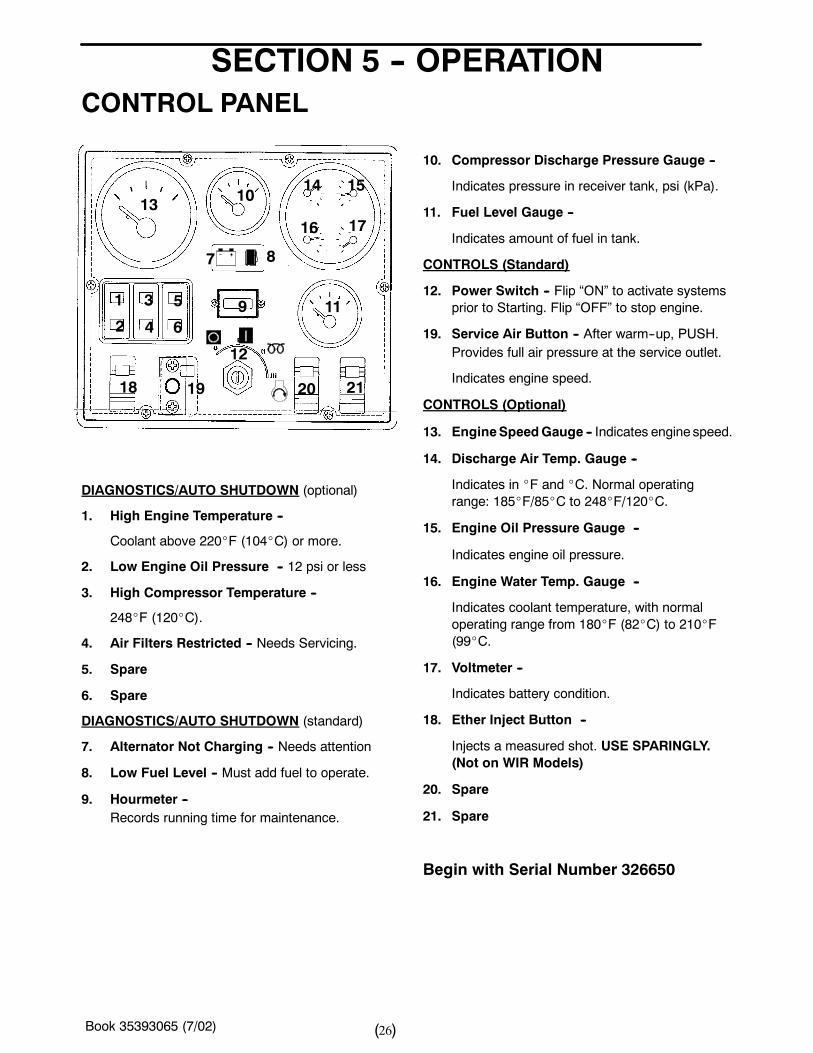
SECTION 5 -- OPERATIONCONTROL PANEL
13 1014 15
16 17
7
9 111 3 5
2 4 6
18 19
12
20 21
8
DIAGNOSTICS/AUTO SHUTDOWN (optional)
1. High Engine Temperature --
Coolant above 220_F (104_C) or more.
2. Low Engine Oil Pressure -- 12 psi or less
3. High Compressor Temperature --
248_F (120_C).
4. Air Filters Restricted -- Needs Servicing.
5. Spare
6. Spare
DIAGNOSTICS/AUTO SHUTDOWN (standard)
7. Alternator Not Charging -- Needs attention
8. Low Fuel Level -- Must add fuel to operate.
9. Hourmeter --Records running time for maintenance.
10. Compressor Discharge Pressure Gauge --
Indicates pressure in receiver tank, psi (kPa).
11. Fuel Level Gauge --
Indicates amount of fuel in tank.
CONTROLS (Standard)
12. Power Switch -- Flip “ON” to activate systemsprior to Starting. Flip “OFF” to stop engine.
19. Service Air Button -- After warm--up, PUSH.Provides full air pressure at the service outlet.
Indicates engine speed.
CONTROLS (Optional)
13. EngineSpeedGauge -- Indicates engine speed.
14. Discharge Air Temp. Gauge --
Indicates in _F and _C. Normal operatingrange: 185_F/85_C to 248_F/120_C.
15. Engine Oil Pressure Gauge --
Indicates engine oil pressure.
16. Engine Water Temp. Gauge --
Indicates coolant temperature, with normaloperating range from 180_F (82_C) to 210_F(99_C.
17. Voltmeter --
Indicates battery condition.
18. Ether Inject Button --
Injects a measured shot. USE SPARINGLY.(Not on WIR Models)
20. Spare
21. Spare
Begin with Serial Number 326650
Book 35393065 (7/02) 27( )
80I
.88Imounting holes
32.85I
-- -- -- -- -- -- -- -- -- -- -- -- -- -- -- -- -- -- -- -- -- -- -- -- -- -- -- -- -- -- -- -- ---- -- -- -- -- -- --
-- -- -- -- -- -- -- -- -- -- -- -- -- -- -- -- -- -- -- -- -- -- -- -- -- -- -- -- -- -- -- -- ---- -- -- -- -- --|
|||||
outside dimensionof base
1.56I
1.38I
|
|||||
29.73I77.24I
Figure X
Mounting Holes
-- -- -- -- -- -- -- -- -- -- -- -- -- -- -- -- -- -- -- -- -- -- -- -- -- -- --
Figure Y
cooling air inletDo Not Block
Do Not Block
Cooling Air Clearance Dimensions
minimum clearancefor cooling air inlets
minimum clearances forcooling air exhaust.
Do Not Block
cooling air inletsDo Not Block
-- --
-- --
-- --
-- -- 8I
2I48I
12I
cooling air inletsboth ends
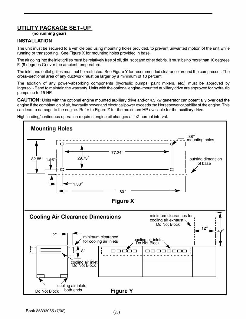
UTILITY PACKAGE SET--UP(no running gear)
INSTALLATION
The unit must be secured to a vehicle bed using mounting holes provided, to prevent unwanted motion of the unit whilerunning or transporting. See Figure X for mounting holes provided in base.
The air going into the inlet grillesmust be relatively free of oil, dirt, soot and other debris. It must benomore than 10degreesF. (5 degrees C) over the ambient temperature.
The inlet and outlet grilles must not be restricted. See Figure Y for recommended clearance around the compressor. Thecross--sectional area of any ductwork must be larger by a minimum of 10 percent.
The addition of any power--absorbing components (hydraulic pumps, paint mixers, etc.) must be approved byIngersoll--Rand to maintain the warranty. Units with the optional engine--mounted auxiliary drive are approved for hydraulicpumps up to 15 HP.
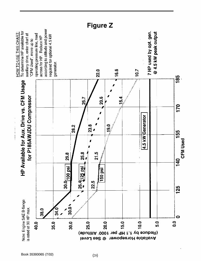
CAUTION: Units with the optional engine mounted auxiliary drive and/or 4.5 kw generator can potentially overload theengine if the combination of air, hydraulic power and electrical power exceeds theHorsepower capability of the engine. Thiscan lead to damage to the engine. Refer to Figure Z for the maximum HP available for the auxiliary drive.
High loading/continuous operation requires engine oil changes at 1/2 normal interval.
Book 35393065 (7/02) 28( )
Figure Z
Book 35393065 (7/02) 29( )
SETTING -- UP (ALL UNITS)
• Position as level as possible. The design of theseunits permits a 15 degree sidewise limit onout--of--level operation.
•When the unit is to be operated out--of--level, it isimportant:
(1) To keep theengine crankcaseoil levelnear thehighlevel mark (with the unit level).
(2) To have the compressor oil level gauge show nomore than mid--scale. Do not overfill either the enginecrankcase or the compressor lubricating oil system.
(3) The side doors must be closed to maintain acooling air path and to avoid recirculation hot air.
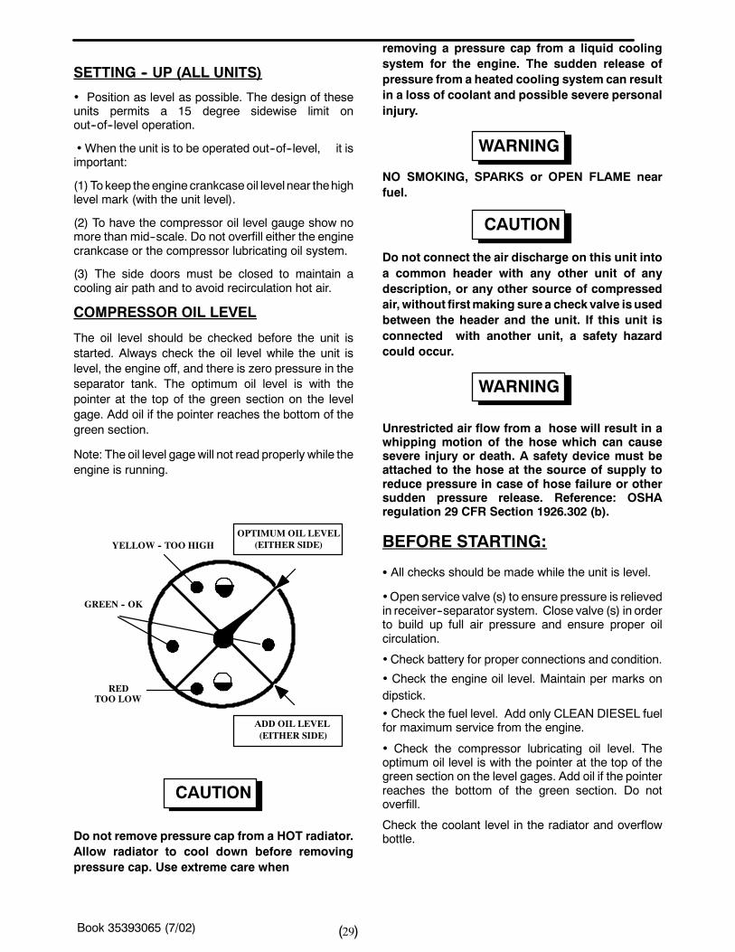
COMPRESSOR OIL LEVEL
The oil level should be checked before the unit isstarted. Always check the oil level while the unit islevel, the engine off, and there is zero pressure in theseparator tank. The optimum oil level is with thepointer at the top of the green section on the levelgage. Add oil if the pointer reaches the bottom of thegreen section.
Note: The oil level gagewill not read properly while theengine is running.
YELLOW -- TOO HIGH
GREEN -- OK
TOO LOWRED
OPTIMUMOIL LEVEL(EITHER SIDE)
ADD OIL LEVEL(EITHER SIDE)
CAUTION
Do not remove pressure cap from a HOT radiator.Allow radiator to cool down before removingpressure cap. Use extreme care when
removing a pressure cap from a liquid coolingsystem for the engine. The sudden release ofpressure from a heated cooling system can resultin a loss of coolant and possible severe personalinjury.
WARNING
NO SMOKING, SPARKS or OPEN FLAME nearfuel.
CAUTION
Do not connect the air discharge on this unit intoa common header with any other unit of anydescription, or any other source of compressedair, without firstmaking surea checkvalve isusedbetween the header and the unit. If this unit isconnected with another unit, a safety hazardcould occur.
WARNING
Unrestricted air flow from a hose will result in awhipping motion of the hose which can causesevere injury or death. A safety device must beattached to the hose at the source of supply toreduce pressure in case of hose failure or othersudden pressure release. Reference: OSHAregulation 29 CFR Section 1926.302 (b).
BEFORE STARTING:
S All checks should be made while the unit is level.
•Open service valve (s) to ensure pressure is relievedin receiver--separator system. Close valve (s) in orderto build up full air pressure and ensure proper oilcirculation.
•Check battery for proper connections and condition.
• Check the engine oil level. Maintain per marks ondipstick.
• Check the fuel level. Add only CLEAN DIESEL fuelfor maximum service from the engine.
• Check the compressor lubricating oil level. Theoptimum oil level is with the pointer at the top of thegreen section on the level gages. Add oil if the pointerreaches the bottom of the green section. Do notoverfill.
Check the coolant level in the radiator and overflowbottle.
Book 35393065 (7/02) 30( )
The coolant must cover the tubes in the top tank(approximately 1 inch high on a clean measuring rodstuck down filler neck). The coolant in the overflowbottle should be above the “COLD” mark for coldengine (<120_F).
A fuel level gauge reading can be obtained withoutstarting the unit, by turning the power switch to “ON”.Afterwards, turn the switch to “OFF”.
Check the fuel level. Use Clean DIESEL fuel formaximum service from the engine.
WARNING
This machine produces loud noise with doorsopen. Extended exposure to loud noise cancause hearing loss. Wear hearing protectionwhen doors or valve (s) are open.
• Close all doors to maintain a cooling air path and toavoid recirculation of hot air. This willmaximize the lifeof the engine and compressor and protect the hearingof surrounding personnel.
• Be sure no one is IN or ON the compressor unit.
STARTINGTurn the POWER switch to “ON”.
If so equipped, place the “Start--Run” Valve Switch,located in the bottom right hand corner of theinstrument panel, to the “Start/Warm--Up” position.
Turn Power switch to “START” position to crankengine. Hold switch in “START” position forapproximately 5 seconds after engine starts.
NOTICEDo not operate the starter motor for more than 10seconds without allowing at least 30 secondscooling time between start attempts.
Release Power Switch (it will automatically move tothe “ON” position)when the engine starts and sustainsrunning.Allow engine to warm up 5 to 10 minutes.
If so equipped, place the “Start--Run” Valve Switch inthe “AIR” position.
Cold Weather Starting:
If so equipped, place the Start--Run valve switch,located in the bottom right hand corner of theinstrument panel, to the “START/WARM--UP”position.
Open manual blowdown valve, if so equipped, andpress ether inject button. Use Ether sparingly. Closemanual blowdown valve after engine is running.
If equipped with the optional cold starting aid(ETHER), operate the valve once or twice ONLYwhilethe engine is cranking.
CAUTION
Ether is an extremely volatile, highly flammablegas. Use sparingly! If too much is injected, theuncontrolled explosion may result in costly dam-age to the engine.
CAUTION
Exercise extreme caution when using a boosterbattery to start. To jump start: Connect the endsof one booster cable to the positive (+) terminalsof each battery. Then connect one endof theothercable to the negative (--) terminal of the boosterbattery and theother end to theengineblock. NOTTO THE NEGATIVE (--) TERMINAL OF THE WEAKBATTERY.
AFTER STARTING:a. Reduce engine speed to IDLE.
b. Disconnect the negative (--) cable from the engine
block first, then from the booster battery.
c. Disconnect positive (+) cable from both batteries.
CAUTION
Do not remove pressure cap from a HOT radiator.Allow radiator to cool down before removingpressure cap. Use extreme care when removing apressure cap from a liquid cooling system for theengine. The sudden release of pressure from aheated cooling system can result in a loss ofcoolant and possible severe personal injury.
Book 35393065 (7/02) 31( )
Hose Reel Operation
To Unwind Hose
1. Disconnect end of hose from docking port at bottomright--hand corner of compressor.
2. Release reel lock pin on left--hand side of reel bypulling and rotating pin toward cradle and releasing it.
3. Pull hose to unwind.
4. Re--engage reel lock pin into reel.
To Retract Hose
1. Release reel lock pin on left--hand side of reel, bypulling and rotating pin toward cradle and releasing it.
2. Push and hold in “Reel Rewind” button at bottomright--hand corner of compressor.
WARNING: Keep Hands AWAY from Hose Reelwhile controlling hose.
3. Secure end of hose into docking port.
4. Reengage reel lock pin into reel.
To Swing Hose Reel Away from Compressor Door
1. Disconnect end of hose from docking port at bottomright--hand corner of compressor.
2. Release latch on right--side of hose reel frame.
3. Swing hose reel out, away from compressor door.
CAUTION: Hose Reel Must Be Returned To It’sLatched Position Before Moving Vehicle.
OPERATION OF OPTIONAL GENERATORThis unit will operate in threemodes, depending on theposition of the generator control switch (located on thefront of the generator control panel).S In “Generator” position, the engine will maintain idlespeed, and the generator will give a constant voltageand frequency output, for use with sensitiveequipment like computers, fusion welders, etc. No
compressed air is available at the service air valves inthis mode.
S In “Gen/Air” position, voltage and frequency will varyas engine speed changes to meet air demands, andshould only be used for lights and hand tools.
S In “Air” position, the generator provides no electricalpower.
1. Start compressor with the Start--Run Switchlocated in the bottom right corner of the instrumentpanel) in the “Start/Warm--up” position.
2. Close all service air valves.
3. Place the start--run switch in the “Run” position.
4. Place the generator control switch in either“Generator” or “Gen/Air” position. The red light on thefront of the generator control panel should glow, andthe voltage meter should read 120 Volts AC.
5. Plugelectric tools or lights into the receptacles onthe front of the generator control panel.
Book 35393065 (7/02) 32( )
Units with Diagnostic Lamps:In a shutdown situation, the function of the panellamps is to indicate what specific failure caused theunit to shut down.These lamps will remain illuminateduntil the Power Switch is turned “OFF”.
UNITS WITH OPTIONAL DIAGNOSTICS LAMPS
NOTICE
None of the panel lamps should be glowing whenma-chine is operating. If they are, shut unit downand referto Trouble Shooting Section.
STOPPINGClose air service valve.
Allow the unit to run at idle for 3 to 5minutes to reducethe engine temperatures.
Turn Power Switch to “OFF” position.
When the engine stops, automatic blowdown valveshould relieve system air pressure. If automatic blow-down valve malfunction is suspected, open manualblowdown valve.
Never allow unit to sit under pressure when engine isnot running.
WARNING
Since the service valve is closed, air downstreamof the valvemay be trapped. Avent hole in theser-vice valve will slowly bleed air from the hose. Donot disconnect hoses until all pressure has beenvented.
AUTOMATIC SHUTDOWNThis unit is protected with sensors (switches) for highdischarge air temperature, high engine coolanttemperature and low engine oil pressure.
Should any of three situations occur, the unit will stop.Before restarting the unit, check these three areas forexcessive heat and fluid level. Other possible causesare listed on the Trouble Shooting Chart.
All units in this family of machines are protected bysensors or switches at the following locations:
(1) Low engine oil pressure, in the engine.
(2) High engine coolant temperature, in the engine.
High Discharge AIR Temperature
(3) At the airend outlet.
(4) In separator tank.
NOTICEDo NOT wire around or bypass a shutdownsensor or switch.
DANGER
Even after pressure is relieved from the receiver--separator system, any air supply line from thecompressor to a tool or a machine could remainunder pressure and cause very serious personalinjury or death. After the compressor stops, care-fully open a valve at any tool or machine to ex-haust the pressure in any line prior to removal orservicing.
Book 35393065 (7/02) 33( )
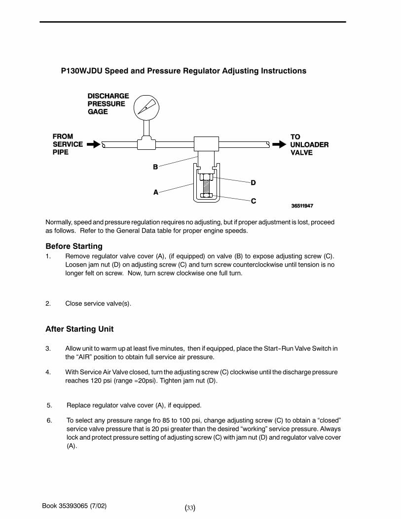
P130WJDU Speed and Pressure Regulator Adjusting Instructions
Normally, speedandpressure regulation requires no adjusting, but if proper adjustment is lost, proceedas follows. Refer to the General Data table for proper engine speeds.
Before Starting1. Remove regulator valve cover (A), (if equipped) on valve (B) to expose adjusting screw (C).
Loosen jam nut (D) on adjusting screw (C) and turn screw counterclockwise until tension is nolonger felt on screw. Now, turn screw clockwise one full turn.
2. Close service valve(s).
After Starting Unit
3. Allow unit to warm up at least fiveminutes, then if equipped, place the Start--RunValve Switch inthe “AIR” position to obtain full service air pressure.
4. With Service Air Valve closed, turn the adjusting screw (C) clockwise until the dischargepressurereaches 120 psi (range =20psi). Tighten jam nut (D).
5. Replace regulator valve cover (A), if equipped.
6. To select any pressure range fro 85 to 100 psi, change adjusting screw (C) to obtain a “closed”service valve pressure that is 20 psi greater than the desired “working” service pressure. Alwayslock and protect pressure setting of adjusting screw (C) with jam nut (D) and regulator valve cover(A).
Book 35393065 (7/02) 34( )
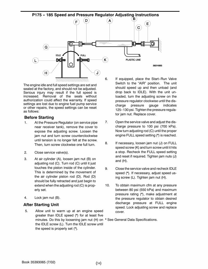
P175 -- 185 Speed and Pressure Regulator Adjusting Instructions
Before Starting1. At the Pressure Regulator (on service pipe
near receiver tank), remove the cover toexpose the adjusting screw. Loosen thejam nut and turn screw counterclockwiseuntil tension is no longer felt at the screw.Then, turn screw clockwise one full turn.
2. Close service valve(s).
The engine idle and full speed settings are set andsealed at the factory, and should not be adjusted.Serious injury may result if the full speed isincreased. Removal of the seals withoutauthorization could affect the warranty. If speedsettings are lost due to engine fuel pump serviceor other repairs, the speed settings can be resetas follows:
3. At air cylinder (A), loosen jam nut (B) onadjusting rod (C). Turn rod (C) until it justtouches the piston inside of the cylinder.This is determined by the movement ofthe air cylinder piston rod (D). Rod (D)should be fully retracted and just begin toextendwhen the adjusting rod (C) is prop-erly set.
4. Lock jam nut (B).
6. If equipped, place the Start--Run ValveSwitch to the “AIR” position. The unitshould speed up and then unload (anddrop back to IDLE). With the unit un-loaded, turn the adjusting screw on thepressure regulator clockwise until the dis-charge pressure gauge indicates125--130 psi. Tighten the pressure regula-tor jam nut. Replace cover.
7. Open the service valve and adjust the dis-charge pressure to 100 psi (700 kPa).Now turn adjusting rod (C) until the properengine FULL speed setting (*) is reached.
8. If necessary, loosen jam nut (J) on FULLspeed screw (K) and turn screwuntil it hitsa stop. Recheck the FULL speed settingand reset if required. Tighten jam nuts (J)and (H).
9. Close the service valve and recheck IDLEspeed (*). If necessary, adjust speed us-ing screw (L). Tighten jam nut (H).
10. To obtain maximum cfm at any pressurebetween 80 psi (550 kPa) and maximumpressure rating (*), make adjustment atthe pressure regulator to obtain desireddischarge pressure at FULL enginespeed. Lock adjusting screw and replacecover.
* See General Data Specifications.
After Starting Unit5. Allow unit to warm up at an engine speed
greater than IDLE speed (*) for at least fiveminutes. Do this by loosening jam nut (H) onthe IDLE screw (L). Turn the IDLE screw untilthe speed is properly set (*).
Book 35393065 (7/02) 35( )
SECTION 6 -- MAINTENANCECAUTION
Any unauthorized modification or failure to maintainthis equipment may make it unsafe and out of factorywarranty.
If performingmore than visual inspections, disconnectbattery cables and open manual blowdown valve.
Use extreme care to avoid contacting hot surfaces(engine exhaust manifold and piping, air receiver andair discharge piping, etc.).
Never operate this machinewith any guards removed.
Inch and metric hardware was used in the design andassembly of this unit. Consult the parts manual forclarification of usage.
Notice: Disregard any maintenance pertaining tocomponents not provided on your machine.
GENERAL
In addition to periodic inspections, many of the
components in these units require periodic servicing
to provide maximum output and performance.Servicing may consist of pre--operation and
post--operation procedures to be performed by the
operating or maintenance personnel. The primaryfunction of preventive maintenance is to prevent
failure, and consequently, the need for repair.
Preventive maintenance is the easiest and the leastexpensive type of maintenance. Maintaining your unit
and keeping it clean at all times will facilitate servicing.
SCHEDULED MAINTENANCE
The maintenance schedule is based on normal
operation of the unit. This page can be reproducedand used as a checklist by the service personnel. In
the event unusual environmental operating conditions
exist, the schedule should be adjusted accordingly.
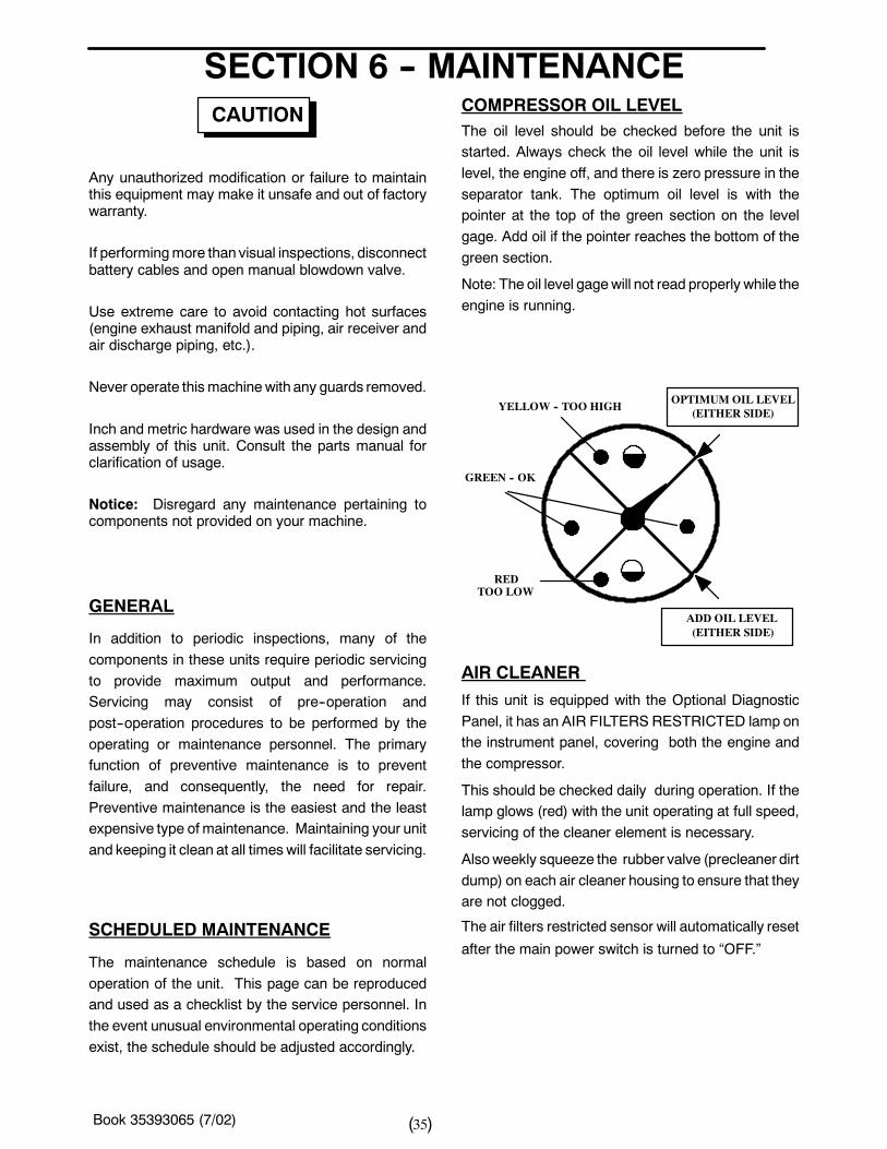
COMPRESSOR OIL LEVELThe oil level should be checked before the unit isstarted. Always check the oil level while the unit is
level, the engine off, and there is zero pressure in the
separator tank. The optimum oil level is with thepointer at the top of the green section on the level
gage. Add oil if the pointer reaches the bottom of the
green section.
Note: The oil level gagewill not read properly while the
engine is running.
YELLOW -- TOO HIGH
GREEN -- OK
TOO LOWRED
OPTIMUMOIL LEVEL(EITHER SIDE)
ADD OIL LEVEL(EITHER SIDE)
AIR CLEANER
If this unit is equipped with the Optional Diagnostic
Panel, it has an AIR FILTERS RESTRICTED lamp onthe instrument panel, covering both the engine and
the compressor.
This should be checked daily during operation. If thelamp glows (red) with the unit operating at full speed,
servicing of the cleaner element is necessary.
Alsoweekly squeeze the rubber valve (precleaner dirt
dump) on each air cleaner housing to ensure that theyare not clogged.
The air filters restricted sensor will automatically reset
after the main power switch is turned to “OFF.”
Book 35393065 (7/02) 36( )
To service the air cleaners on all units proceed as fol-
lows:
1. Loosen outer wing nut and remove with cover.Remove Element.
2. Inspect air cleaner housing for any conditionthat might cause a leak and correct asnecessary.
3. Wipe inside of air cleaner housing with a clean,damp cloth to remove any dirt accumulation,especially in the area where the element sealsagainst the housing.
4. Inspect element by placing a bright light insideand rotating slowly. If any holes or tears arefound in the paper, discard this element. If noruptures are found, the element can becleaned.
5. If a new air filter element is to be used check itclosely for shipping damage.
6. Install cleaned or new elements in the reverseorder to the above. Tighten wing nut firmly.
7. Inspect to ensure that the end cap seals tightly360 degrees around the air cleaner body.
In the event that the filter element must be reused
immediately, compressed air cleaning (as follows) is
recommended since the element must be thoroughly
dry. Direct compressed air through the element in the
direction opposite to the normal air flow through the
element.
Move the nozzle up and down while rotating theelement. Be sure to keep the nozzle at least one inch(25.4 mm) from the pleated paper.
NOTE: To prevent damage to the element, never
exceed a maximum air pressure of 100 psi (700
kPa).
In the event the element is contaminated with dry dirt,
oil or greasy dirt deposits, and a new element is not
available, cleaning can be accomplished by washing,
using the air cleaner element manufacturer’s recom-
mendations.
NOTE: It is recommended that replacement ele-
ments be installed in the unit. The elements just
removed for cleaning can be washed and stored
as future replacement elements.
In addition, the air cleaner system (housing and
piping) should be inspected every month for any
leakage paths or inlet obstructions. Make sure the air
cleaner mounting bolts and clamps are tight. Check
the air cleaner housing for dents or damage which
could lead to a leak. Inspect theair transfer tubing from
the air cleaner to the compressor and the engine for
leaks.
Make sure that all clamps and flange joints are tight.
GAUGES
The instruments or gauges are essential for safety,
maximum productivity and long service life of the
machine. Inspect the gauges and test any diagnostic
lamps prior to start--up. During operation observe the
gauges and any lamps for proper functioning. Refer to
Operating Controls, for the normal readings.
Book 35393065 (7/02) 37( )
FUEL TANKCLEAN fuel in the fuel tanks is vitally important and
every precaution should be taken to ensure that only
clean fuel is poured or pumped into the tank.
When filling the fuel tank on this unit, bymethods other
than a pump and hose, use a CLEAN non--metallic
funnel.
BATTERYKeep the battery posts--to--cable connections clean,
tight and lightly coated with a grease. Also the
electrolyte level in each cell should cover the top of the
plates. If necessary, top--up with clean distilled water.
FASTENERSVisually check entire unit in regard to bolts, nuts andscrews being properly secured. Spot check severalcapscrews andnuts for proper torque. If any are foundloose, a more thorough inspection must be made.Take corrective action.
RADIATORNOTICE
The use of water alone in this engine can result inmajor engine failure.
HOSESEach month it is recommended that all of the intakelines to and from the air cleaners, the engine coolingsystem hoses and all of the flexible hoses used for air,oil, and fuel be inspected.
To ensure freedom from air leaks, all rubber hosejoints and the screw--type hose clamps must beabsolutely tight. Regular inspection of theseconnections for wear or deterioration is necessary.
Premature wear of both the engine and compressor isASSURED whenever dust--laden air is permitted toenter the engine’s combustion chamber or thecompressor intake.
The flexible hoses used in the fuel, oil and air lines onthese units are primarily used for their ability toaccommodate relative movement betweencomponents. It is important they be periodicallyinspected for wear and deterioration. It is alsoimportant the operator does not use the hoses asconvenient hand hold or steps. Such use can causeearly cover wear and hose failure.
NOTICE
Piping systems operating at less than 150 psi(1050 kPa) may use a special nylon tubing. Theassociated fittings are also of a special “push--in”design. If so, features are as follows:
Pulling on the tubing will cause the inner sleeve towithdraw and compress, thus tightening theconnection. The tubing can be withdrawn only whileholding the sleeve against the fitting. The tubing canbe removed and replaced numerous times withoutlosing its sealing ability.
To install the nylon tubing, make a mark (with tape orgrease pencil) approximately 7/8 inch from the end ofthe tubing. Insert the tubing into the sleeve and“push--in” past the first resistance to the bottom. Themark should be approximately 1/16 inch from thesleeve, for the 3/8 inch O.D. tubing; 1/8 inch for the0.25 inch O.D. tubing. This will ensure that the tubingis fully engaged in the sealing mechanism.
NOTICEThe oil filter must be replaced every 500 hours ofoperation or three (3) months, whichever comesfirst. On new or overhauled units, replace the ele-ment after the first 50 and 150 hours of operation;thereafter, service the oil filter every 500 hours.
To service the oil filters it will first be necessary to shutthe unit down. Wipe off any external dirt and oil fromthe exterior of the filter to minimize any contaminationfrom entering the lubrication system. Proceed asfollows:
Book 35393065 (7/02) 38( )
WARNING
Highpressureair can cause severe injury ordeathfrom hot oil and flying parts. Always relievepressure before removing caps, plugs, covers orother parts from pressurized air system.
1. Open the service air valve(s) to ensure thatsystem is relieved of all pressure. Close thevalve(s).
2. Turn the spin--on filter element counterclockwiseto remove it from the filter housing. Inspect the filter.
NOTICEIf there is any indication of formation ofvarnishes,shellacs or lacquers on the oil filter element, it is awarning the compressor lubricating oil has im-proper characteristics and should be immediatelychanged.
3. Inspect the oil filter head to be sure the gasket wasremoved with the oil filter element. Clean the gasketseal area on the oil filter head.
NOTICEInstalling a new oil filter element when the oldgasket remains on the filter head, will cause an oilleak and can cause property damage
1. Lubricate the new filter gasket with the same oilbeing used in the machine.
2. Install new filter by turning element clockwise untilgasket makes initial contact. Tighten an additional 1/2to 3/4 turn.
3. Start unit and allow to build up to rated pressure.Check for leaks before placing unit back into service.
COMPRESSOR OIL COOLER
Thecompressor lubricating and cooling oil is cooledby
means of the fin and tube--type oil cooler, located
beside the radiator. The lubricating and cooling oil,
flowing internally through the core section, is cooledby
the air stream from the cooling fan flowing past the
core section. When grease, oil anddirt accumulate on
the exterior surfaces of the oil cooler, its efficiency is
impaired.
Each month it is recommended that the oil cooler be
cleaned by directing compressed air which contains a
nonflammable, non--caustic safety solvent through
the core of the oil cooler. This should remove the
accumulation of grease, oil and dirt from the exterior
surfaces of the oil cooler core so that the entire cooling
area can transmit the heat of the lubricating and
cooling oil to the air stream.
In the event foreign deposits, such as sludge and lac-
quer, accumulate in the oil cooler to the extent that its
cooling efficiency is impaired, a resulting high dis-
charge air temperature is likely to occur, causing shut
down of the unit. To correct this situation it will be nec-
essary to clean it using a cleaning compound in accor-
dance with the manufacturer’s recommendations.
Book 35393065 (7/02) 39( )
COMPRESSOR OILThe lubricating and cooling oil must be replaced every500 hours of operation or six (6) months, whichevercomes first.
RECEIVER--SEPARATOR SYSTEMS
WARNING
Highpressureair can cause severe injury ordeathfrom hot oil and flying parts. Always relievepressure before removing caps, plugs, covers orother parts from pressurized air system.
S Open service valve at end of machine.
S Ensure pressure is relieved, with BOTH:
-- Discharge air pressure gauge reads zero (0).
-- No air discharging from service valve.
When draining oil, remove plug from the separatortank drain fitting.
When adding oil, remove and replace (make tight)
plug on side of separator tank.
In the compressor lubricating and cooling system,separation of the oil from the compressed air takesplace in the receiver--separator tank. As thecompressed air enters the tank, the change in velocityand direction drop out most of the oil from the air.
Additional separation takes place in the oil separatorelement which is located in the top of the tank.
Any oil accumulation in this separator element iscontinuously drained off bymeans of a scavenge tubewhich returns the accumulated oil to the system.
Book 35393065 (7/02) 40( )
The life of the oil separator element is dependent uponthe operating environment (soot, dust, etc.) andshould be replaced every twelve months or 2000hours. To replace the element proceed as follows:
S Ensure the tank pressure is zero.
S Disconnect the hose from the scavenge tube.
S Remove scavenge tube from tank cover.
S Disconnect service line from cover.
S Remove cover mounting screws.
S Remove cover and element.
S Remove any gasket material left on cover or tank.
S Install new element.
NOTICE
Do not remove staples from the element/gasketconnection.
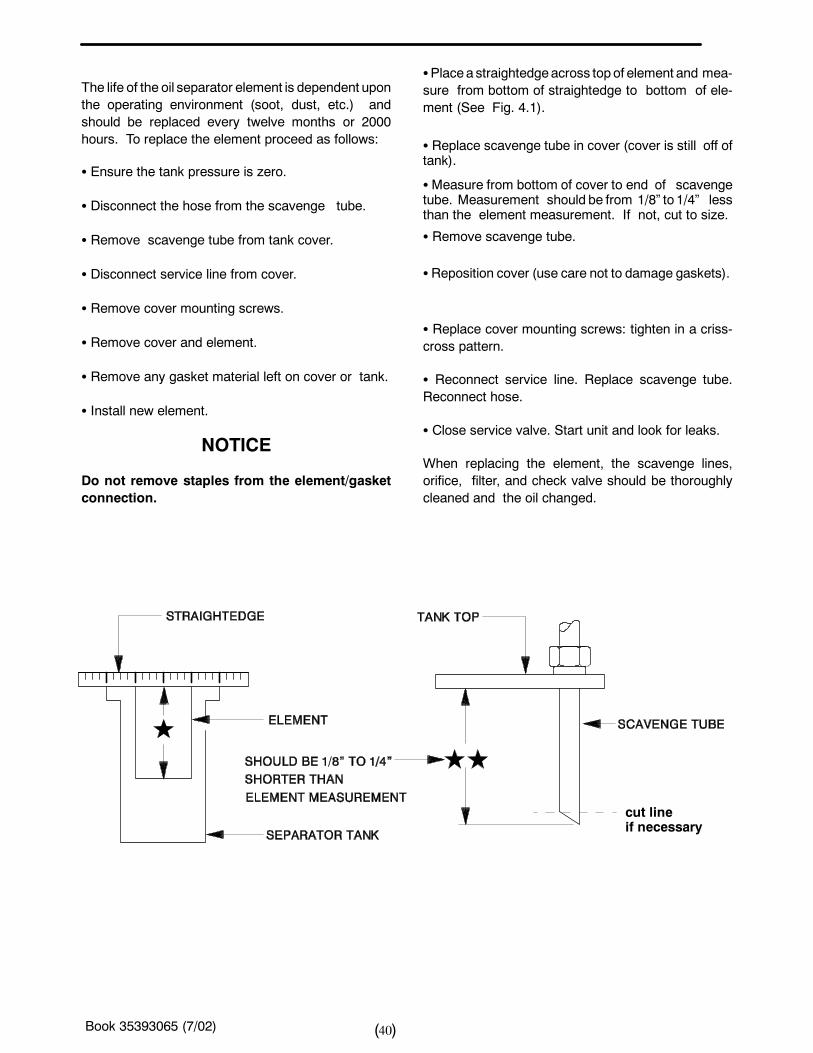
SPlacea straightedgeacross topof element and mea-sure from bottom of straightedge to bottom of ele-ment (See Fig. 4.1).
S Replace scavenge tube in cover (cover is still off oftank).
SMeasure from bottom of cover to end of scavengetube. Measurement should be from 1/8” to 1/4” lessthan the element measurement. If not, cut to size.
S Remove scavenge tube.
SReposition cover (use care not to damage gaskets).
S Replace cover mounting screws: tighten in a criss-cross pattern.
S Reconnect service line. Replace scavenge tube.Reconnect hose.
S Close service valve. Start unit and look for leaks.
When replacing the element, the scavenge lines,orifice, filter, and check valve should be thoroughlycleaned and the oil changed.
cut lineif necessary
Book 35393065 (7/02) 41( )
SCAVENGE LINE
WARNING
Highpressureair can cause severe injury ordeathfrom hot oil and flying parts. Always relievepressure before removing caps, plugs, covers orother parts from pressurized air system.
The scavenge line originates at the receiver--separa-tor tank cover and terminates at the compressor air-end near the oil filter element. An orifice check valveis located on the scavenge tube.
Once a year or every 1000 hours of operation,whichever comes first, replace the separator elementand clean the scavenge orifice/check valve.
NOTE:Excessiveoil carry--overmaybe causedbyan oil--logged separator element. Do not replaceelement without first performing the followingmaintenance procedure:
1. Check oil level. Maintain as indicated earlier inthis section.
2. Thoroughly clean scavenge line, any orificeand check valve.
3. Assure minimum pressure valve/orifice is op-erational.
4. Rununit at rated operating pressure for 30 to 40minutes to permit element to clear itself.
EXTERIOR FINISH CAREThis unit was painted and heat cured at the factorywith a high quality, thermoset polyester powder coat-ing. The following carewill ensure the longest possiblelife from this finish.
1. If necessary to remove dust, pollen, etc. fromhousing, wash with water and soap or dishwashing liquid detergent. Do not scrub with arough cloth, pad, etc.
2. If grease removal is needed, a fast evaporatingalcohol or chlorinated solvent can be used. Note:This may cause some dulling of the paint finish.
3. If the paint has faded or chalked, the use of acommercial grade, non--abrasive car wax maypartially restore the color and gloss.
Field Repair of Texture Paint
1. The sheet metal should be washed andclean of foreign material and thenthoroughly dried.
2. Clean and remove all grease and wax fromthe area to be painted using Duponts3900SCleaner prior to sanding.
3. Use 320 grit sanding paper to repair anyscratches or defects necessary.
4. Scuff sand theentire area to bepaintedwitha red scotch brite pad.
5. Wipe the area clean using Duponts 3900S.
6. Blow and tack the area to be painted.
7. Apply a smooth coat of Duponts 1854STuffcoat Primer to all bare metal areas andallow to dry.
8. Apply 2 medium -- wet coats of Duponts222S Adhesion Promoter over the entirearea to be painted, with a 5 minute flash inbetween coats.
9. To apply the texture coat, use Duponts1854S Tuffcoat Primer. The propertechnique to do this is to spray the TuffcoatPrimer using a pressure pot and use about2--5 pounds of air pressure. This will allowthe primer to splatter causing the texturedlook. Note: you must be careful not to puttoo much primer on at one time, this willeffect the amount of texture that you aretrying to achieve. Allow the texture coat toflash for 20 minutes or until dry to touch.
10. Apply any of Duponts Topcoat Finishessuch as Imront or Centarit according tothe label instructions.
Note: To re--topcoat the textured surfaces whensheet metal repairs are not necessary,follow steps 1, 2, 4, 5, 6, 8 and 10.
Book 35393065 (7/02) 42( )
MAINTENANCE SCHEDULE
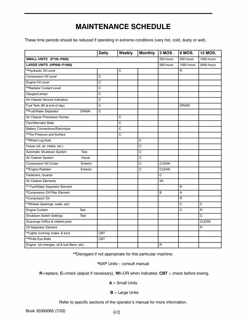
These time periods should be reduced if operating in extreme conditions (very hot, cold, dusty or wet).
Daily Weekly Monthly 3 MOS . 6 MOS. 12 MOS.SMALL UNITS (P100--P600) 250 hours 500 hours 1000 hours
LARGE UNITS (HP600--P1600) 500 hours 1000 hours 2000 hours
**Hydraulic Oil Level C R
Compressor Oil Level C
Engine Oil Level C
**Radiator Coolant Level C
Gauges/Lamps C
Air Cleaner Service Indicators C
Fuel Tank (fill at end of day) C DRAIN
**Fuel/Water Separator DRAIN C
Air Cleaner Precleaner Dumps C
Fan/Alternator Belts C
Battery Connections/Electrolyte C
**Tire Pressure and Surface C
**Wheel Lug Nuts C
Hoses (oil, air, intake, etc.) C
Automatic Shutdown System Test C
Air Cleaner System Visual C
Compressor Oil Cooler Exterior C CLEAN
**Engine Radiator Exterior C CLEAN
Fasteners, Guards C
Air Cleaner Elements WI
** Fuel/Water Separator Element R
*Compressor Oil Filter Element B A
*Compressor Oil R
**Wheels (bearings, seals, etc) C C
Engine Coolant Test C R
Shutdown Switch Settings Test C
Scavenge Orifice & related parts CLEAN
Oil Separator Element R
**Lights (running, brake, & turn) CBT
**Pintle Eye Bolts CBT
Engine (oil changes, oil & fuel filters, etc) R
**Disregard if not appropriate for this particular machine.
*NXP Units -- consult manual
R=replace, C=check (adjust if necessary), WI=OR when indicated, CBT = check before towing.
A = Small Units
B = Large Units
Refer to specific sections of the operator’s manual for more information.
Book 35393065 (7/02) 43( )
SECTION 7 -- LUBRICATION
GENERAL INFORMATION
Lubrication is an essential part of preventive mainte-nance, affecting to a great extent the useful life of theunit. Different lubricants are neededandsomecompo-nents in the unit requiremore frequent lubrication thanothers. Therefore, it is important that the instructionsregarding types of lubricants and the frequency of theirapplication be explicitly followed. Periodic lubricationof themovingparts reduces to aminimum thepossibil-ity of mechanical failures.
The Preventive Maintenance Schedule shows thoseitems requiring regular service and the interval inwhich they should be performed. A regular serviceprogram should be developed to include all items andfluids. These intervals are based on averageoperating conditions. In the event of extremely severe(hot, cold, dusty or wet) operating conditions, morefrequent lubrication than specified may be necessary.Details concerning lubrication of the running gear arein Maintenance Section.
All filters and filter elements for air and compressor lu-bricant must be obtained through Ingersoll--Rand toassure the proper size and filtration for the compres-sor.
COMPRESSOR OIL CHANGE
These units are normally furnished with an initial sup-ply of oil sufficient to allow operation of the unit for ap-proximately 6 months or 1000 hours, whichevercomes first. If a unit has been completely drained of alloil, it must be refilled with new oil before it is placed inoperation. Refer to specifications in LubricationTable.
NOTICE
Some oil types are incompatible when mixed and re-sult in the formationof varnishes, shellacs, or lacquerswhich may be insoluble. Such deposits can cause se-rious troubles including clogging of the filters. Wherepossible, do NOT mix oils of different types and avoidmixing different brands. A type or brand change isbest made at the time of a complete oil drain and refill.
If the unit has been operated for the time/ hours men-tioned above, it should be completely drained of oil. Ifthe unit has been operated under adverse conditions,or after long periods in storage, an earlier change peri-od may be necessary as oil deteriorates with time aswell as by operating conditions.
WARNING
Highpressureair can cause severe injury ordeathfrom hot oil and flying parts. Always relieve pres-surebefore removing caps, plugs, covers orotherparts frompressurized air system. Ensure the fol-lowing conditions are met:
-- Discharge air pressure gauge reads zero (0).-- No air discharging from an “open” manualblowdown valve.
Anoil change is good insuranceagainst theaccumula-tion of dirt, sludge, or oxidized oil products.
Completely drain the receiver-- separator, piping, andoil cooler. If the oil is drained immediately after theunithas been run for some time, most of the sediment willbe in suspension and, therefore, will drain more readi-ly. However, the fluid will be hot and care must be tak-en to avoid contact with the skin or eyes.
After the unit has been completely drained of all old oil,close the drain valve. Add oil in the specified quantityat the filler plug. Tighten the filler plug and run thema-chine to circulate the oil. Check the oil level WHENRUNNING AT FULL LOAD. If not near the middle ofthe sight tube, stop the unit andmake corrections. DONOT OVERFILL.
NOTICE
Ingersoll--Rand provides compressor oil specificallyformulated for Portable Compressors and requires theuse of these fluids in order to obtain extended limitedairend warranty.
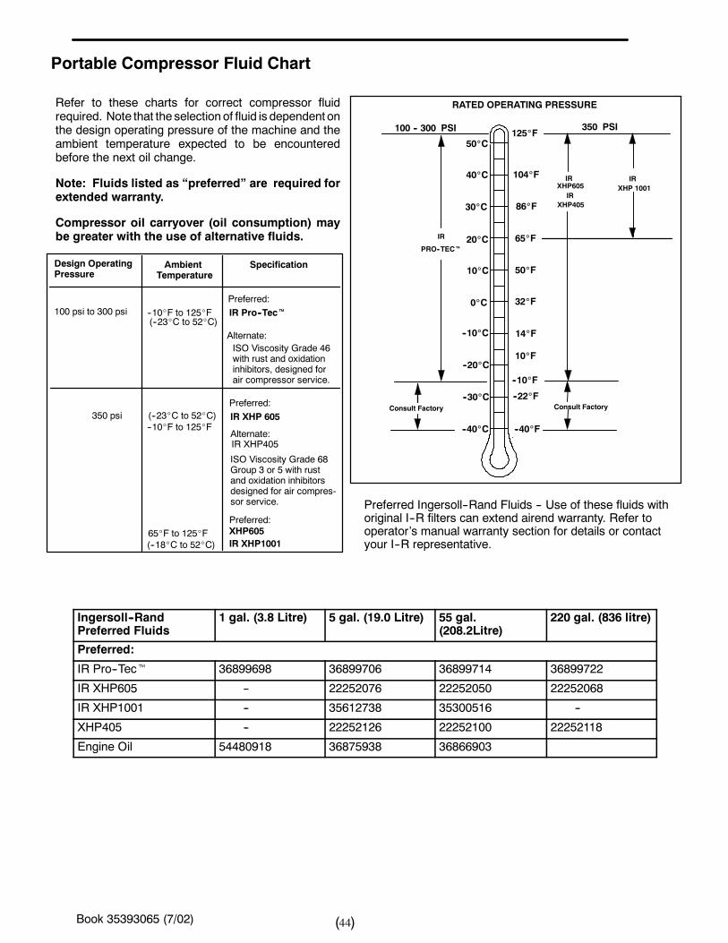
Book 35393065 (7/02) 44( )
XHP605
IR
PRO--TECt
100 -- 300 PSI
RATED OPERATING PRESSURE
350 PSI
IRXHP 1001
10_F
125_F50_C
40_C
30_C
20_C
10_C
0_C
--10_C
--20_C
--30_C
--40_C
104_F
86_F
65_F
50_F
32_F
14_F
--10_F
--22_F
--40_F
Refer to these charts for correct compressor fluidrequired. Note that the selection of fluid is dependent onthe design operating pressure of the machine and theambient temperature expected to be encounteredbefore the next oil change.
Note: Fluids listed as “preferred” are required forextended warranty.
Compressor oil carryover (oil consumption) maybe greater with the use of alternative fluids.
100 psi to 300 psi
350 psi
Design OperatingPressure
AmbientTemperature
Specification
Portable Compressor Fluid Chart
(--23_C to 52_C)--10_F to 125_F IR Pro--Tect
IR XHP 605--10_F to 125_F(--23_C to 52_C)
65_F to 125_FIR XHP1001
Preferred Ingersoll--Rand Fluids -- Use of these fluids withoriginal I--R filters can extend airend warranty. Refer tooperator’s manual warranty section for details or contactyour I--R representative.
XHP405
(--18_C to 52_C)
XHP605
Alternate:IR XHP405
Preferred:
Preferred:
Alternate:
Preferred:
Consult Factory Consult Factory
ISO Viscosity Grade 46with rust and oxidationinhibitors, designed forair compressor service.
ISO Viscosity Grade 68Group 3 or 5 with rustand oxidation inhibitorsdesigned for air compres-sor service.
IR
IR
Ingersoll--RandPreferred Fluids
1 gal. (3.8 Litre) 5 gal. (19.0 Litre) 55 gal.(208.2Litre)
220 gal. (836 litre)
Preferred:
IR Pro--Tect 36899698 36899706 36899714 36899722
IR XHP605 -- 22252076 22252050 22252068
IR XHP1001 -- 35612738 35300516 --
XHP405 -- 22252126 22252100 22252118
Engine Oil 54480918 36875938 36866903
Book 35393065 (7/02) 45( )
SECTION 8 -- Trouble Shooting
Trouble shooting for a portable air compressoris anorganized study of a particular problemorseries of problems and a planned method ofprocedure for investigation and correction.The trouble shooting chart that followsincludes some of the problems that anoperator may encounter during the operationof a portable compressor.
The chart does not attempt to list all of thetroubles that may occur, nor does it attempt togive all of the answers for correction of theproblems. The chart does give thoseproblems that aremost apt to occur. Touse thetrouble shooting chart:
A. Find the “complaint” depicted as a boldheading.
B. Follow down that column to find the po-tential cause or causes. The causes arelisted in order (1,2,3 etc.) to suggest anorder to follow in trouble shooting.
INTRODUCTION
ACTION PLAN
A. Think Before Acting
Study the problem thoroughly and ask yourselfthese questions:
(1) What were thewarning signals that precededthe trouble?
(2) Has a similar trouble occurred before?(3) What previous maintenance work has been
done?(4) If the compressor will still operate, is it safe to
continue operating it tomake further checks?
B. Do The Simplest Things First
Most troubles are simple and easily corrected. Forexample, most complaints are “low capacity” which maybe caused by too low an engine speed or “compressorover-- heats” which may be caused by low oil level.
Always check the easiest and most obvious things first;following this simple rule will save time and trouble.
D. Find And Correct Basic Cause
After a mechanical failure has been corrected, be sure tolocate and correct the cause of the trouble so the samefailure will not be repeated. A complaint of “prematurebreakdown” may be corrected by repairing any improperwiring connections, but something caused the defectivewiring. The cause may be excessive vibration.
C. Double Check Before Disassembly
The source of most compressor troubles can be tracednot to one component alone, but to the relationship of onecomponent with another. Too often, a compressor canbepartially disassembled in search of the cause of a certaintrouble and all evidence is destroyed during disassembly.Check again to be sure an easy solution to the problemhas not been overlooked.
Note: For trouble shooting electrical problems, refer tothe Wiring Diagram Schematic found in Parts ListSection.
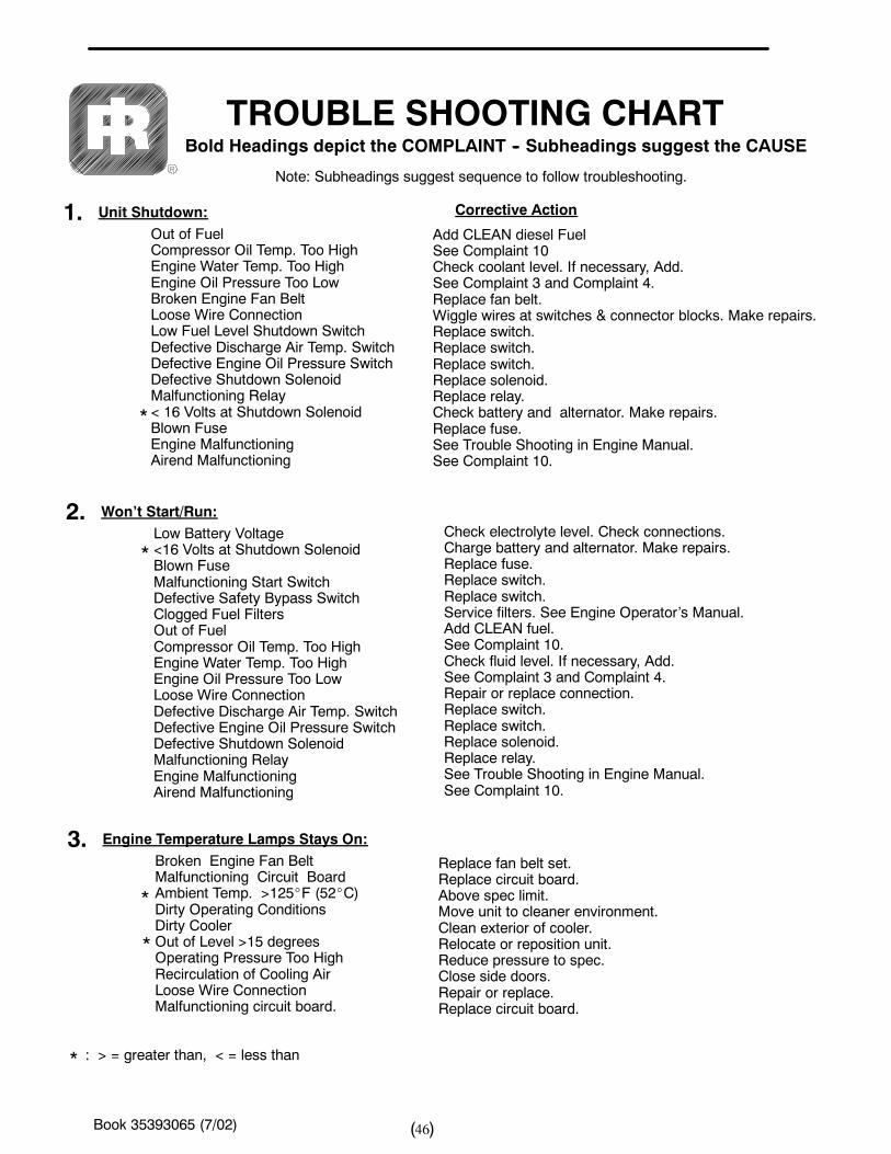
Book 35393065 (7/02) 46( )
Unit Shutdown:Out of FuelCompressor Oil Temp. Too HighEngine Water Temp. Too HighEngine Oil Pressure Too LowBroken Engine Fan BeltLoose Wire ConnectionLow Fuel Level Shutdown SwitchDefective Discharge Air Temp. SwitchDefective Engine Oil Pressure SwitchDefective Shutdown SolenoidMalfunctioning Relay< 16 Volts at Shutdown SolenoidBlown FuseEngine MalfunctioningAirend Malfunctioning
Won’t Start/Run:Low Battery Voltage<16 Volts at Shutdown SolenoidBlown FuseMalfunctioning Start SwitchDefective Safety Bypass SwitchClogged Fuel FiltersOut of FuelCompressor Oil Temp. Too HighEngine Water Temp. Too HighEngine Oil Pressure Too LowLoose Wire ConnectionDefective Discharge Air Temp. SwitchDefective Engine Oil Pressure SwitchDefective Shutdown SolenoidMalfunctioning RelayEngine MalfunctioningAirend Malfunctioning
Engine Temperature Lamps Stays On:Broken Engine Fan BeltMalfunctioning Circuit BoardAmbient Temp. >125_F (52_C)Dirty Operating ConditionsDirty CoolerOut of Level >15 degreesOperating Pressure Too HighRecirculation of Cooling AirLoose Wire ConnectionMalfunctioning circuit board.
TROUBLE SHOOTING CHARTBold Headings depict the COMPLAINT -- Subheadings suggest the CAUSE
Note: Subheadings suggest sequence to follow troubleshooting.
Add CLEAN diesel FuelSee Complaint 10Check coolant level. If necessary, Add.See Complaint 3 and Complaint 4.Replace fan belt.Wiggle wires at switches & connector blocks. Make repairs.Replace switch.Replace switch.Replace switch.Replace solenoid.Replace relay.Check battery and alternator. Make repairs.Replace fuse.See Trouble Shooting in Engine Manual.See Complaint 10.
Check electrolyte level. Check connections.Charge battery and alternator. Make repairs.Replace fuse.Replace switch.Replace switch.Service filters. See Engine Operator’s Manual.Add CLEAN fuel.See Complaint 10.Check fluid level. If necessary, Add.See Complaint 3 and Complaint 4.Repair or replace connection.Replace switch.Replace switch.Replace solenoid.Replace relay.See Trouble Shooting in Engine Manual.See Complaint 10.
Replace fan belt set.Replace circuit board.Above spec limit.Move unit to cleaner environment.Clean exterior of cooler.Relocate or reposition unit.Reduce pressure to spec.Close side doors.Repair or replace.Replace circuit board.
1.
2.
3.
*
*
*
*
Corrective Action
* : > = greater than, < = less than
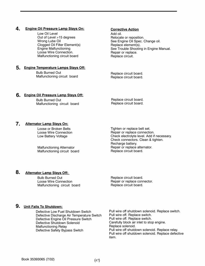
Book 35393065 (7/02) 47( )
Engine Oil Pressure Lamp Stays On:Low Oil LevelOut of Level >15 degreesWrong Lube OilClogged Oil Filter Element(s)Engine MalfunctioningLoose Wire Connection.Malfunctioning circuit board
Engine Temperature Lamps Stays Off:Bulb Burned OutMalfunctioning circuit board
Engine Oil Pressure Lamp Stays Off:Bulb Burned OutMalfunctioning circuit board
Alternator Lamp Stays On:Loose or Broken BeltsLoose Wire ConnectionLow Battery Voltage
Alternator Lamp Stays Off:Bulb Burned OutLoose Wire ConnectionMalfunctioning circuit board
Unit Fails To Shutdown:Defective Low Fuel Shutdown SwitchDefective Discharge Air Temperature SwitchDefective Engine Oil Pressure SwitchDefective Shutdown SolenoidMalfunctioning RelayDefective Safety Bypass Switch
Add oil.Relocate or reposition.See Engine Oil Spec. Change oil.Replace element(s).See Trouble Shooting in Engine Manual.Repair or replace.Replace circuit.
Replace circuit board.Replace circuit board.
Replace circuit board.Replace circuit board.
Tighten or replace belt set.Repair or replace connection.Check electrolyte level. Add if necessary.Check connectors. Clean & tighten.Recharge battery.Repair or replace alternator.Replace circuit board.
Replace circuit board.Repair or replace connector.Replace circuit board.
Pull wire off shutdown solenoid. Replace switch.Pull wire off. Replace switch.Pull wire off. Replace switch.Carefully block air inlet to stop engine.Replace solenoid.Pull wire off shutdown solenoid. Replace relay.Pull wire off shutdown solenoid. Replace defectiveitem.
4.
5.
6.
7.
8.
9.
Corrective Action
Malfunctioning AlternatorMalfunctioning circuit board
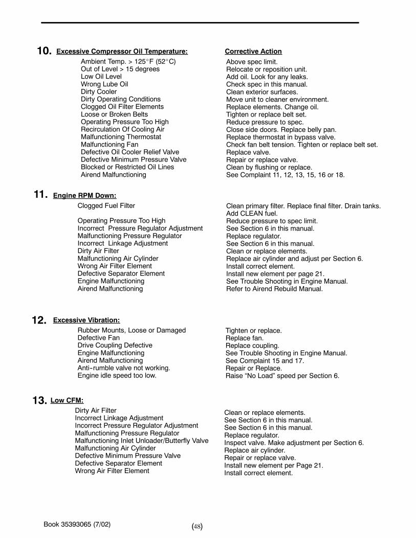
Book 35393065 (7/02) 48( )
Excessive Compressor Oil Temperature:Ambient Temp. > 125_F (52_C)Out of Level > 15 degreesLow Oil LevelWrong Lube OilDirty CoolerDirty Operating ConditionsClogged Oil Filter ElementsLoose or Broken BeltsOperating Pressure Too HighRecirculation Of Cooling AirMalfunctioning ThermostatMalfunctioning FanDefective Oil Cooler Relief ValveDefective Minimum Pressure ValveBlocked or Restricted Oil LinesAirend Malfunctioning
Engine RPM Down:Clogged Fuel Filter
Operating Pressure Too HighIncorrect Pressure Regulator AdjustmentMalfunctioning Pressure RegulatorIncorrect Linkage AdjustmentDirty Air FilterMalfunctioning Air CylinderWrong Air Filter ElementDefective Separator ElementEngine MalfunctioningAirend Malfunctioning
Excessive Vibration:Rubber Mounts, Loose or DamagedDefective FanDrive Coupling DefectiveEngine MalfunctioningAirend MalfunctioningAnti--rumble valve not working.Engine idle speed too low.
Low CFM:Dirty Air FilterIncorrect Linkage AdjustmentIncorrect Pressure Regulator AdjustmentMalfunctioning Pressure RegulatorMalfunctioning Inlet Unloader/Butterfly ValveMalfunctioning Air CylinderDefective Minimum Pressure ValveDefective Separator ElementWrong Air Filter Element
Above spec limit.Relocate or reposition unit.Add oil. Look for any leaks.Check spec in this manual.Clean exterior surfaces.Move unit to cleaner environment.Replace elements. Change oil.Tighten or replace belt set.Reduce pressure to spec.Close side doors. Replace belly pan.Replace thermostat in bypass valve.Check fan belt tension. Tighten or replace belt set.Replace valve.Repair or replace valve.Clean by flushing or replace.See Complaint 11, 12, 13, 15, 16 or 18.
Clean primary filter. Replace final filter. Drain tanks.Add CLEAN fuel.Reduce pressure to spec limit.See Section 6 in this manual.Replace regulator.See Section 6 in this manual.Clean or replace elements.Replace air cylinder and adjust per Section 6.Install correct element.Install new element per page 21.See Trouble Shooting in Engine Manual.Refer to Airend Rebuild Manual.
10.
11.
12.
13.Clean or replace elements.See Section 6 in this manual.See Section 6 in this manual.Replace regulator.Inspect valve. Make adjustment per Section 6.Replace air cylinder.Repair or replace valve.Install new element per Page 21.Install correct element.
Tighten or replace.Replace fan.Replace coupling.See Trouble Shooting in Engine Manual.See Complaint 15 and 17.Repair or Replace.Raise “No Load” speed per Section 6.
Corrective Action
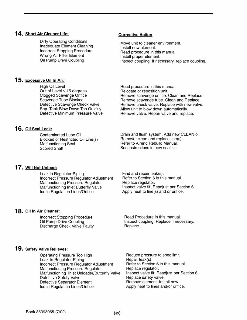
Book 35393065 (7/02) 49( )
Short Air Cleaner Life:
Dirty Operating ConditionsInadequate Element CleaningIncorrect Stopping ProcedureWrong Air Filter ElementOil Pump Drive Coupling
Excessive Oil In Air:High Oil LevelOut of Level > 15 degreesClogged Scavenge OrificeScavenge Tube BlockedDefective Scavenge Check ValveSep. Tank Blow Down Too QuicklyDefective Minimum Pressure Valve
Oil Seal Leak:Contaminated Lube OilBlocked or Restricted Oil Line(s)Malfunctioning SealScored Shaft
Will Not Unload:Leak in Regulator PipingIncorrect Pressure Regulator AdjustmentMalfunctioning Pressure RegulatorMalfunctioning Inlet Butterfly ValveIce in Regulation Lines/Orifice
Oil In Air Cleaner:Incorrect Stopping ProcedureOil Pump Drive CouplingDischarge Check Valve Faulty
Safety Valve Relieves:Operating Pressure Too HighLeak In Regulator PipingIncorrect Pressure Regulator AdjustmentMalfunctioning Pressure RegulatorMalfunctioning Inlet Unloader/Butterfly ValveDefective Safety ValveDefective Separator ElementIce in Regulation Lines/Orifice
Move unit to cleaner environment.Install new element.Read procedure in this manual.Install proper element.Inspect coupling. If necessary, replace coupling.
Read procedure in this manual.Relocate or reposition unit.Remove scavenge orifice. Clean and Replace.Remove scavenge tube. Clean and Replace.Remove check valve. Replace with new valve.Allow unit to blow down automatically.Remove valve. Repair valve and replace.
Drain and flush system. Add new CLEAN oil.Remove, clean and replace line(s).Refer to Airend Rebuild Manual.See instructions in new seal kit.
Find and repair leak(s).Refer to Section 6 in this manual.Replace regulator.Inspect valve fit. Readjust per Section 6.Apply heat to line(s) and or orifice.
Read Procedure in this manual.Inspect coupling. Replace if necessary.Replace.
Reduce pressure to spec limit.Repair leak(s).Refer to Section 6 in this manual.Replace regulator.Inspect valve fit. Readjust per Section 6.Replace safety valve.Remove element. Install new.Apply heat to lines and/or orifice.
14.
15.
16.
17.
18.
19.
Corrective Action
Book 35393065 (7/02) 50( )
SECTION 9 -- PARTS ORDERINGGENERAL
This publication, which contains an illustrated parts
breakdown, has been prepared as an aid in locating
those parts whichmay be required in themaintenance
of the unit. All of the compressor parts, listed in the
parts breakdown, are manufactured with the same
precision as the original equipment. For the greatest
protection always insist on genuine Ingersoll--Rand
Company parts for your compressor.
NOTICEIngersoll--Rand Company can bear no responsibilityfor injury or damages resulting directly from the use ofnon--approved repair parts.
Ingersoll--Rand Company service facilities and partsare available worldwide. There are Ingersoll-- RandCompany Construction Equipment Group Sales Of-fices and authorized distributors located in the princi-pal cities of theUnited States. In Canada our custom-ers are serviced by the Canadian Ingersoll--RandCompany, Limited. There are also Ingersoll--Rand In-ternational autonomous companies and authorizeddistributors located in the principal cities throughoutthe free world.
Special order partsmay not be included in thismanual.Contact the Mocksville Parts Department with the unitserial number for assistance with these special parts.
DESCRIPTION
The illustratedparts breakdown illustrates and lists the
various assemblies, subassemblies anddetailedparts
which make up this particular machine. This covers
the standard models and the more popular options
that are available.
A series of illustrations showeach part distinctly and in
location relative to the other parts in the assembly.
The part number, the description of the part and the
quantity of parts required are shown on each
illustration or on adjacent page. The quantities
specified are the number of parts used per one
assembly and are not necessarily the total number of
parts used in the machine. Where no quantity is
specified the quantity is assumed to be one.
Each description of a part is based upon the “noun
first” method, i.e., the identifying noun or item name is
always the first part of the description. The nounname
is generally followed by a single descriptive modifier.
The descriptive modifier may be followed by words or
abbreviations such as upper, lower, inner, outer, front,
rear, RH, LH, etc. when they are essential.
In referring to the rear, the front or to either side of theunit, always consider the drawbar end of the unit asthe front. Standing at the rear of the unit facing thedrawbar (front) will determine the right and left sides.
FASTENERS
Both SAE/inch and ISO/metric hardware have beenused in the design and assembly of these units. In thedisassembly and reassembly of parts, extreme caremust be taken to avoid damaging threads by the useofwrong fasteners. In order to clarify the proper usageand for exact replacement parts, all standardfasteners have been identified by part number, sizeand description. This will enable a customer to obtainfasteners locally rather than ordering from the factory.These parts are identified in tables that will be found atthe rear of theparts illustrations. Any fastener that hasnot been identified by both part number and size is aspecially engineered part that must be ordered by partnumber to obtain the exact replacement part.
Book 35393065 (7/02) 51( )
MARKINGS AND DECALS
NOTICEDo not paint over safetywarnings or instructional
decals. If safety warning decals become illegible,
immediately order replacements from the factory.
Part numbers for original individual decals and theirmounting locations are shown within Parts ListSection. These are available as long as a particularmodel is in production.
Afterwards, service sets of exterior decals and currentproduction safety warning decals are available.Contact the Product Support Group at Mocksville foryour particular needs and availability.
HOW TO USE PARTS LIST
a. Turn to Parts List.
b. Locate the area or system of the compressor inwhich thedesiredpart is usedand find illustrationpage number.
c. Locate thedesiredpart on the illustration by visu-al identification and make note of part numberand description.
HOW TO ORDER
The satisfactory ordering of parts by a purchaser isgreatly dependent upon the proper use of all availableinformation. By supplying your nearest sales office,autonomous company or authorized distributor, withcomplete information, you will enable them to fill yourorder correctly and to avoid any unnecessary delays.
In order that all avoidable errors may be eliminated,the following instructions are offered as a guide to thepurchaser when ordering replacement parts:
a. Always specify the model number of the unit asshown on the general data decal attached to theunit.
b. Always specify the serial number of the unit.THIS IS IMPORTANT. The serial number of theunit will be found stamped on a plate attached tothe unit. (The serial number on the unit is alsopermanently stamped in the metal of the frameside rail.)
c. Always specify the number of the parts list pub-lication.
d. Always specify the quantity of parts required.
e. Always specify the part number, as well as thedescription of the part, or parts, exactly as it isgiven on the parts list illustration.
In the event parts are being returned to your nearest
sales office, autonomous company or authorized dis-
tributor, for inspection or repair, it is important to in-
clude the serial number of theunit fromwhich theparts
were removed.
TERMS AND CONDITIONS ON PARTS ORDERS
Acceptance: Acceptance of an offer is expressly lim-
ited to the exact terms contained herein. If purchas-
er’s order form is used for acceptance of an offer, it is
expressly understood and agreed that the terms and
conditions of such order form shall not apply unless
expressly agreed to by Ingersoll--Rand Company
(“Company”) in writing. No additional or contrary
terms will be binding upon the Company unless ex-
pressly agreed to in writing.
Taxes: Any tax or other governmental charge now or
hereafter leviedupon theproduction, sale, use or ship-
ment of material and equipment ordered or sold is not
included in theCompany’s price andwill be charged to
and paid for by the Purchaser.
Shipping dates shall be extended for delays due to
acts of God, acts of Purchaser, acts of Government,
fires, floods, strikes, riot, war, embargo, transportation
shortages, delay or default on the part of the Compa-
ny’s vendors, or any other cause beyond the Compa-
ny’s reasonable control.
Should Purchaser request special shipping instruc-
tion, such as exclusive use of shipping facilities, in-
cluding air freight when common carrier has been
quoted and before change order to purchase order
can be received by the Company, the additional
charges will be honored by the Purchaser.
Book 35393065 (7/02) 52( )
Warranty: The Company warrants that parts man-
ufactured by it will be as specified and will be free from
defects in materials and workmanship. The Compa-
ny’s liability under this warranty shall be limited to the
repair or replacement of any part which was defective
at the timeof shipment providedPurchaser notifies the
Company of any such defect promptly upondiscovery,
but in no event later than three (3) months from the
date of shipment of such part by the Company. The
only exception to the previous statement is the ex-
tended warranty as it applies to the special airend ex-
change program.
Repairs and replacements shall be made by theCom-
panyF.O.B. point of shipment. TheCompany shall not
be responsible for costs of transportation, removal or
installation.
Warranties applicable to material and equipment
supplied by the Company but wholly manufactured by
others shall be limited to the warranties extended to
theCompany by themanufacturerwhichareable tobe
conveyed to the Purchaser.
Delivery: Shippingdates are approximate. TheCom-
panywill usebest efforts to ship by thedates specified;
however, theCompany shall not be liable for any delay
or failure in the estimated delivery or shipment of ma-
terial and equipment or for any damages suffered by
reason thereof.
The companymakes no other warranty or representa-
tion of any kind whatsoever, expressed or implied, ex-
cept that of title, and all implied warranties, including
any warranty of merchantability and fitness for a par-
ticular purpose, are hereby disclaimed.
Limitation of Liability:
The remedies of the Purchaser set forth herein are ex-
clusive, and the total liability of the Company with re-
spect to this order whether based on contract, warran-
ty, negligence, indemnity, strict liability or otherwise,
shall not exceed the purchase price of the part upon
which such liability is based.
The Company shall in no event be liable to the Pur-
chaser, any successors in interest or any beneficiary
of this order for any consequential, incidental, indirect,
special or punitive damages arising out of this order or
any breach thereof, or any defect in, or failure of, or
malfunction of the parts hereunder, whether based
upon loss of use, lost profits or revenue, interest, lost
goodwill, work stoppage, impairment of other goods,
loss by reason of shutdown or non-- operation, in-
creased expenses of operation or claims of customers
of Purchaser for service interruption whether or not
such loss or damage is based on contract, warranty,
negligence, indemnity, strict liability or otherwise.
Book 35393065 (7/02) 53( )
AIREND EXCHANGE PROGRAM
Your Ingersoll--Rand Company Construction Equip-
ment Group Sales Offices and authorized distributors
as well as Ingersoll--Rand International autonomous
companies and authorized distributors now
have an airend exchange program to benefit portable
compressor users.
On the airend exchange program the exchange
price is determined by the age and condition of
the airend andmay be classified by one of the fol-
lowing categories.
Category “A”: Theairendmust not beover two years
old and must have reusable rotor housing(s) and ro-
tor(s).
Category “B”: The airend must be between two and
five years old and returned with two or more reusable
major castings.
Category “C”: The airend must be over five years
old.
Your nearest sales office, autonomous company or
authorized distributor must first contact the Parts Ser-
vice Department at the factory at which your portable
air compressor was manufactured for an airend ex-
change number. The airend must be tagged with this
preassigned number and returned to the factory pre-
paid. The airend must be intact, with no excluded
parts, otherwise the exchange agreement may be
cancelled. Thewarranty onan exchangeor factory re-
built airend is 365 days.
Airends being returned to the factory in connec-
tionwith aWARRANTYCLAIMmust beprocessed
through the Customer Service Department. If re-
turned without a Warranty MRR (Material Return
Request) Number, no warranty claim will be con-
sidered.
-- 53 --Book 35393065 (2/02)
CONTENTS
Frame Complete
Engine Complete
Oil By--pass Vlv Complete
Airend Assembly
Air Service Complete
Seperator Tank Complete
Air Intake Complete
PARTS LIST
Air Cleaner Assembly
Air and Oil Piping
Air and Oil Piping
Instrument Panel
Remote Filters Complete
Fuel Tank Complete
Battery Assembly
Cooling Complete
Airend Complete
Central Drains
Wiring Diagram
Decal Location
Enclosure Complete
Acoustic Panels
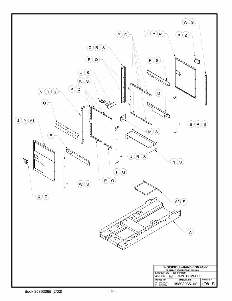
-- 54 --Book 35393065 (2/02)
FRAME COMPLETE4/25/97
P--185AWJDUP--130AWJDU --
PORTABLE COMPRESSOR DIVISIONDESCRIPTION
MODEL NO.
INGERSOLL--RAND COMPANY
DATE/DWN BY:
bd
B
A
N
D
G
EM
R S
RC
Q
Q
P
P
T
P
U
W
X
S
QP
Q
Q
R S
S
S
Z
RV S
YJ A1
K S
YH A1
F S
X Z
W S
S
L S
A2 S
B35393065--02MANUAL NO.
4/98DATE/REV:
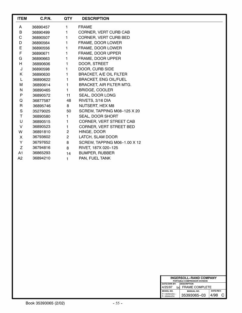
-- 55 --Book 35393065 (2/02)
ITEM C.P.N. QTY DESCRIPTION
ABCDEFGHJKLMNPQRSTUVWXYZA1
36890457368904993689050736890564368905563689067136890663
3689059836890606
368906303689062236890614
3689057236877587
36891810
368905803689051536890523
3679481636865293
3679360236797652
1111111
11
111
1148
2
111
28
FRAMECORNER, VERT CURB CABCORNER, VERT CURB BEDFRAME, DOOR LOWERFRAME, DOOR LOWERFRAME, DOOR UPPERFRAME, DOOR UPPER
DOOR, CURB SIDEDOOR, STREET
BRACKET, A/E OIL FILTERBRACKET, ENG OIL/FUELBRACKET, AIR FILTER MTG.
SEAL, DOOR LONGRIVETS, 3/16 DIA
HINGE, DOOR
SEAL, DOOR SHORTCORNER, VERT STREET CABCORNER, VERT STREET BED
RIVET, 187X 020--125BUMPER, RUBBER
LATCH, SLAM DOORSCREW, TAPPING M06--1.00 X 12
36890465 1 BRIDGE, COOLER
36895746 8 NUTSERT, HEX M8
PORTABLE COMPRESSOR DIVISIONDESCRIPTION
MODEL NO.
INGERSOLL--RAND COMPANY
DATE/DWN BY:
bd FRAME COMPLETE4/25/97
P--185AWJDUP--130AWJDU --
35279025 50 SCREW, TAPPING M08--125 X 20
814
A2 36894210 PAN, FUEL TANK1
C35393065--03MANUAL NO.
4/98DATE/REV:
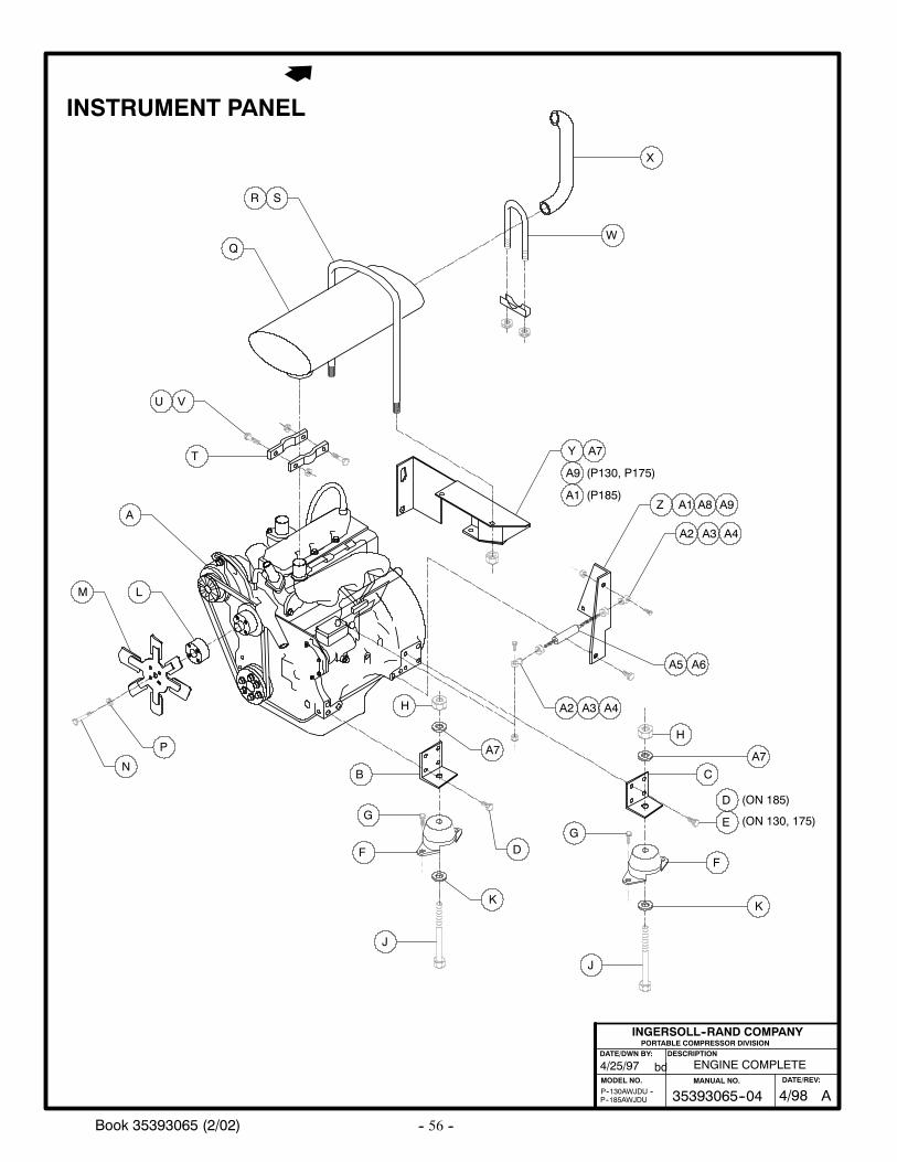
-- 56 --Book 35393065 (2/02)
INSTRUMENT PANEL
K
E
X
WQ
V
T
F
LM
P
NC
K
D
G
F
J
B
G
A
SR
Y
Z A1
A2 A3 A4
A2 A3 A4
A5 A6
D
(ON 130, 175)
U
ENGINE COMPLETE
PORTABLE COMPRESSOR DIVISIONDESCRIPTION
MODEL NO.
INGERSOLL--RAND COMPANY
DATE/DWN BY:
bd4/25/97
P--185AWJDUP--130AWJDU --
J
H
A8
A7
(ON 185)
A9
A1A9
(P130, P175)
(P185)
H
A7A7
A35393065--04MANUAL NO.
4/98DATE/REV:
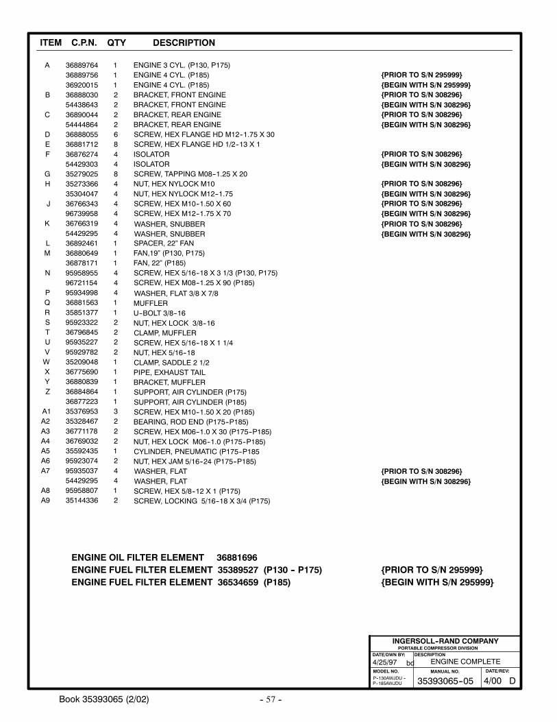
-- 57 --Book 35393065 (2/02)
ITEM C.P.N. QTY DESCRIPTION
ENGINE FUEL FILTER ELEMENT 35389527 (P130 -- P175)ENGINE OIL FILTER ELEMENT 36881696
ENGINE COMPLETE
PORTABLE COMPRESSOR DIVISIONDESCRIPTION
MODEL NO.
INGERSOLL--RAND COMPANY
DATE/DWN BY:
bd4/25/97
P--185AWJDUP--130AWJDU --
ENGINE FUEL FILTER ELEMENT 36534659 (P185)
BEGIN WITH S/N 295999PRIOR TO S/N 295999
BEGIN WITH S/N 295999PRIOR TO S/N 295999
D35393065--05MANUAL NO.
4/00DATE/REV:
A
B
C
DEF
GH
J
K
LM
N
PQRSTUVWXYZ
A1A2A3A4A5A6A7
A8A9
368897643688975636920015368880305443864336890044544448643688805536881712368762745442930335279025352733663530404736766343967399583676631954429295368924613688064936878171959589559672115495934998368815633585137795923322367968459593522795929782352090483677569036880839368848643687722335376953353284673677117836769032355924359592307495935037544292959595880735144336
111222268448444444111444112222111113222124412
ENGINE 3 CYL. (P130, P175)ENGINE 4 CYL. (P185)ENGINE 4 CYL. (P185)BRACKET, FRONT ENGINEBRACKET, FRONT ENGINEBRACKET, REAR ENGINEBRACKET, REAR ENGINESCREW, HEX FLANGE HD M12--1.75 X 30SCREW, HEX FLANGE HD 1/2--13 X 1ISOLATORISOLATORSCREW, TAPPING M08--1.25 X 20NUT, HEX NYLOCK M10NUT, HEX NYLOCK M12--1.75SCREW, HEX M10--1.50 X 60SCREW, HEX M12--1.75 X 70
SPACER, 22” FANFAN,19” (P130, P175)FAN, 22” (P185)SCREW, HEX 5/16--18 X 3 1/3 (P130, P175)SCREW, HEX M08--1.25 X 90 (P185)
WASHER, SNUBBERWASHER, SNUBBER
WASHER, FLAT 3/8 X 7/8MUFFLERU--BOLT 3/8--16NUT, HEX LOCK 3/8--16CLAMP, MUFFLERSCREW, HEX 5/16--18 X 1 1/4NUT, HEX 5/16--18CLAMP, SADDLE 2 1/2PIPE, EXHAUST TAILBRACKET, MUFFLERSUPPORT, AIR CYLINDER (P175)SUPPORT, AIR CYLINDER (P185)SCREW, HEX M10--1.50 X 20 (P185)BEARING, ROD END (P175--P185)SCREW, HEX M06--1.0 X 30 (P175--P185)NUT, HEX LOCK M06--1.0 (P175--P185)CYLINDER, PNEUMATIC (P175--P185NUT, HEX JAM 5/16--24 (P175--P185)WASHER, FLATWASHER, FLATSCREW, HEX 5/8--12 X 1 (P175)SCREW, LOCKING 5/16--18 X 3/4 (P175)
BEGIN WITH S/N 308296PRIOR TO S/N 308296
BEGIN WITH S/N 308296PRIOR TO S/N 308296
BEGIN WITH S/N 308296PRIOR TO S/N 308296
BEGIN WITH S/N 308296PRIOR TO S/N 308296
BEGIN WITH S/N 308296PRIOR TO S/N 308296
BEGIN WITH S/N 308296PRIOR TO S/N 308296
BEGIN WITH S/N 308296PRIOR TO S/N 308296
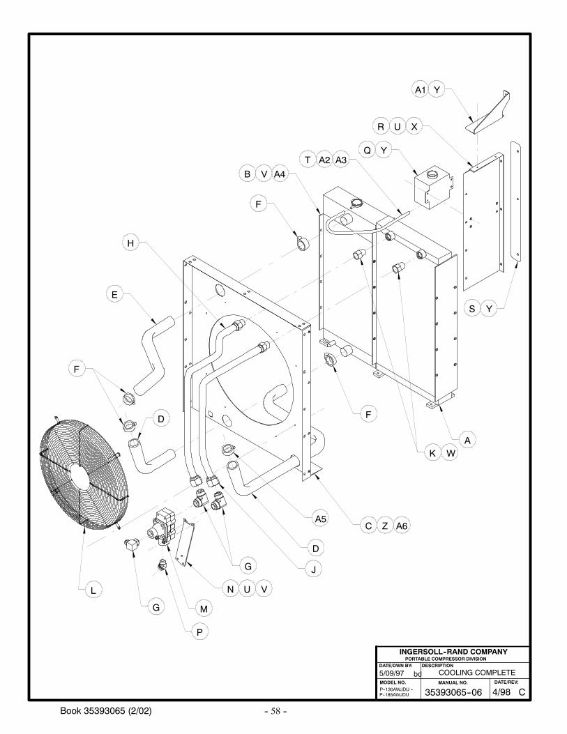
-- 58 --Book 35393065 (2/02)
COOLING COMPLETE
PORTABLE COMPRESSOR DIVISIONDESCRIPTION
MODEL NO.
INGERSOLL--RAND COMPANY
DATE/DWN BY:
bd5/09/97
P--185AWJDUP--130AWJDU --
A
C
D F
G
A4
F
F
E
H
J
K
L
M
N
P
G
D
U
Y
W
U V
Y
R
A1
Z
YS
A3Q
A2T
X
VB
A5A6
C35393065--06MANUAL NO.
4/98DATE/REV:
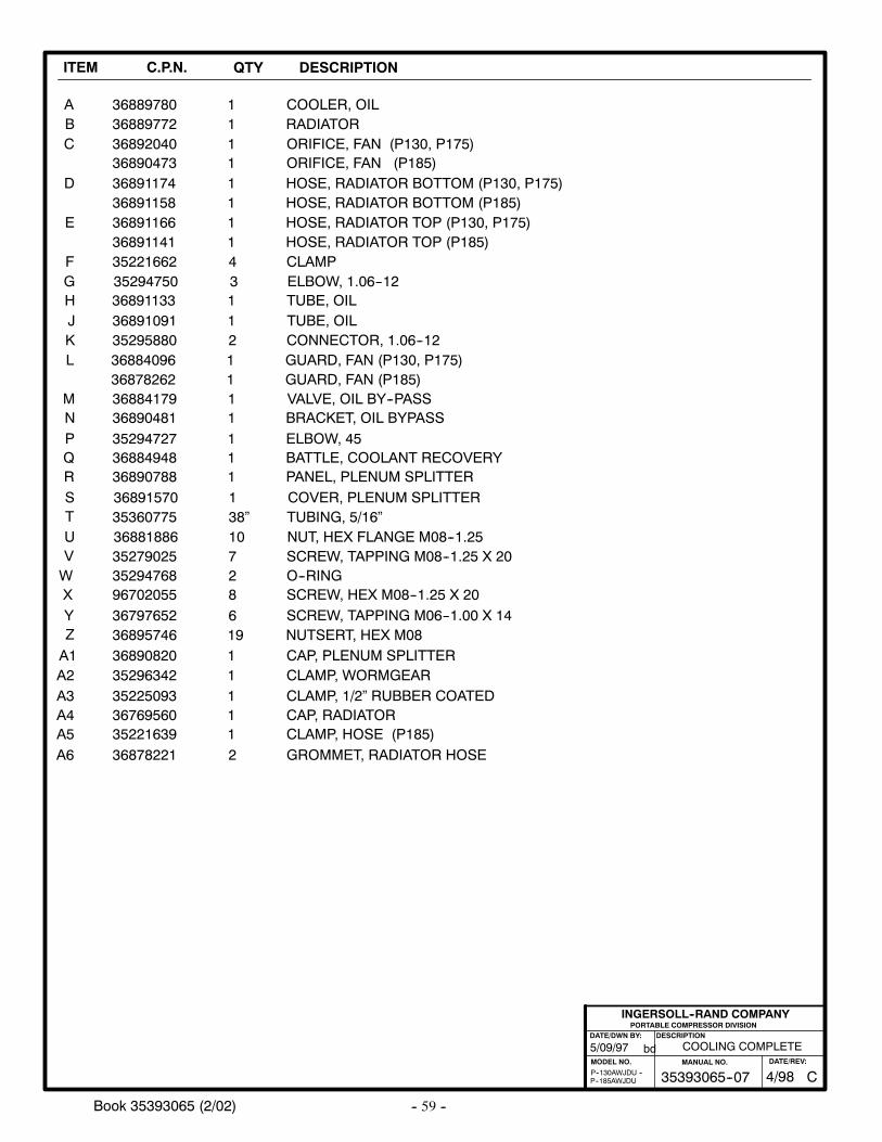
-- 59 --Book 35393065 (2/02)
ITEM C.P.N. QTY DESCRIPTION
ABC
D
E
3688977236892040
36891174
11
1
RADIATORORIFICE, FAN (P130, P175)
HOSE, RADIATOR BOTTOM (P130, P175)
35221662 4 CLAMP
36889780 1 COOLER, OIL
FGHJKL
MNPQRSTUVWXYZ
35294750
3689109135295880
35294727
36891570
36891133
3527902535294768967020553679765236895746
3
12
1
1
1
728619
ELBOW, 1.06--12
TUBE, OILCONNECTOR, 1.06--12
ELBOW, 45
COVER, PLENUM SPLITTER
TUBE, OIL
SCREW, TAPPING M08--1.25 X 20O--RINGSCREW, HEX M08--1.25 X 20
NUTSERT, HEX M08
36881886 10 NUT, HEX FLANGE M08--1.25
36884096
36884179
36890788
1
1
1
GUARD, FAN (P130, P175)
VALVE, OIL BY--PASS
PANEL, PLENUM SPLITTER36884948 1 BATTLE, COOLANT RECOVERY
PORTABLE COMPRESSOR DIVISIONDESCRIPTION
MODEL NO.
INGERSOLL--RAND COMPANY
DATE/DWN BY:
bd
P--185AWJDUP--130AWJDU --
36890481 1 BRACKET, OIL BYPASS
COOLING COMPLETE5/09/97
36891158 1 HOSE, RADIATOR BOTTOM (P185)
36890473 1 ORIFICE, FAN (P185)
SCREW, TAPPING M06--1.00 X 14
A1 36890820 1 CAP, PLENUM SPLITTER
36891166 1 HOSE, RADIATOR TOP (P130, P175)36891141 1 HOSE, RADIATOR TOP (P185)
A2 35296342 1 CLAMP, WORMGEAR
35360775 38” TUBING, 5/16”
A3 35225093 1 CLAMP, 1/2” RUBBER COATEDA4 36769560 1 CAP, RADIATOR
36878262 1 GUARD, FAN (P185)
A5 35221639 1 CLAMP, HOSE (P185)A6 36878221 2 GROMMET, RADIATOR HOSE
C35393065--07MANUAL NO.
4/98DATE/REV:
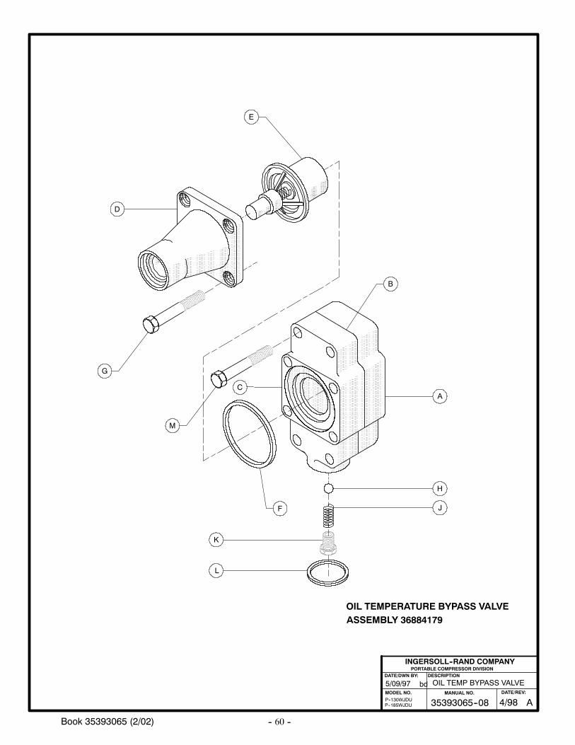
-- 60 --Book 35393065 (2/02)
A
B
H
J
L
F
C
G
E
D
K
OIL TEMPERATURE BYPASS VALVEASSEMBLY 36884179
OIL TEMP BYPASS VALVE5/09/97
P--185WJDUP--130WJDU
PORTABLE COMPRESSOR DIVISIONDESCRIPTION
MODEL NO.
INGERSOLL--RAND COMPANY
DATE/DWN BY:
bd
M
A35393065--08MANUAL NO.
4/98DATE/REV:
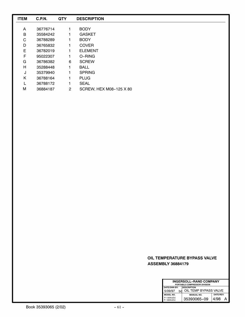
-- 61 --Book 35393065 (2/02)
ITEM C.P.N. QTY DESCRIPTION
ABCDEFGHJKLM
3677671435584242367882893676583236782019950223073678638235288448353799403678816436788172
11111161111
BODYGASKETBODYCOVERELEMENTO--RINGSCREWBALLSPRINGPLUGSEAL
OIL TEMPERATURE BYPASS VALVEASSEMBLY 36884179
36884187 2 SCREW, HEX M08--125 X 80
OIL TEMP BYPASS VALVE
PORTABLE COMPRESSOR DIVISIONDESCRIPTION
MODEL NO.
INGERSOLL--RAND COMPANY
DATE/DWN BY:
bd5/09/97
P--185WJDUP--130WJDU A35393065--09
MANUAL NO.
4/98DATE/REV:
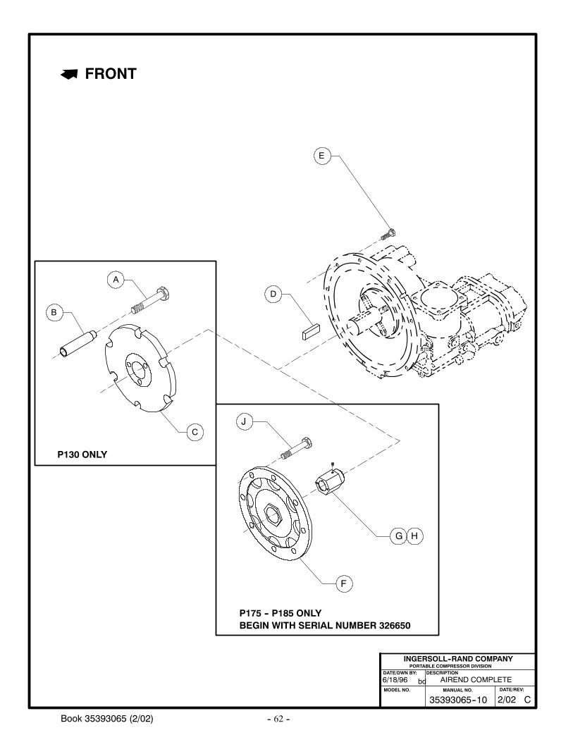
-- 62 --Book 35393065 (2/02)
C
E
D
A
B
AIREND COMPLETE6/18/96
PORTABLE COMPRESSOR DIVISIONDESCRIPTION
MODEL NO.
INGERSOLL--RAND COMPANY
DATE/DWN BY:
bd
C35393065--10MANUAL NO.
2/02DATE/REV:
J
G
F
H
BEGIN WITH SERIAL NUMBER 326650P175 -- P185 ONLY
FRONT
P130 ONLY
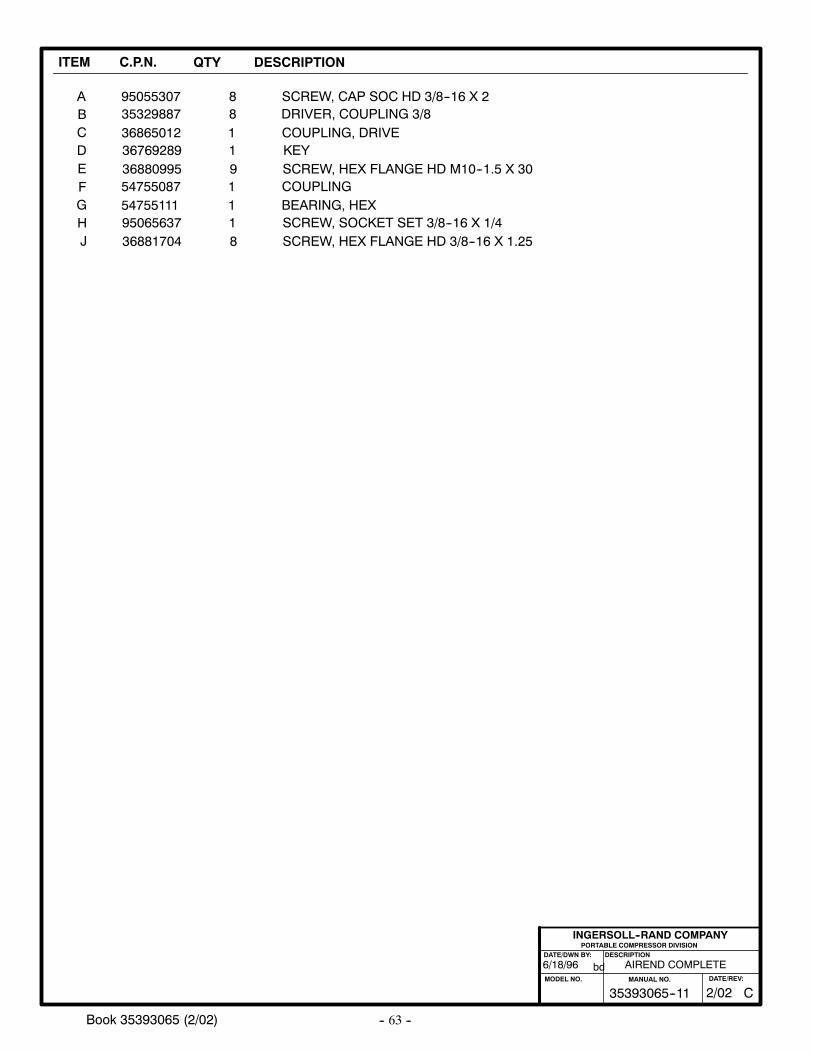
-- 63 --Book 35393065 (2/02)
ITEM C.P.N. QTY DESCRIPTION
ABCDE
9505530735329887368650123676928936880995
88119
SCREW, CAP SOC HD 3/8--16 X 2DRIVER, COUPLING 3/8COUPLING, DRIVEKEYSCREW, HEX FLANGE HD M10--1.5 X 30
AIREND COMPLETE6/18/96
PORTABLE COMPRESSOR DIVISIONDESCRIPTION
MODEL NO.
INGERSOLL--RAND COMPANY
DATE/DWN BY:
bd
C35393065--11MANUAL NO.
2/02DATE/REV:
H
FG
J
54755087547551119506563736881704
1118
COUPLINGBEARING, HEXSCREW, SOCKET SET 3/8--16 X 1/4SCREW, HEX FLANGE HD 3/8--16 X 1.25
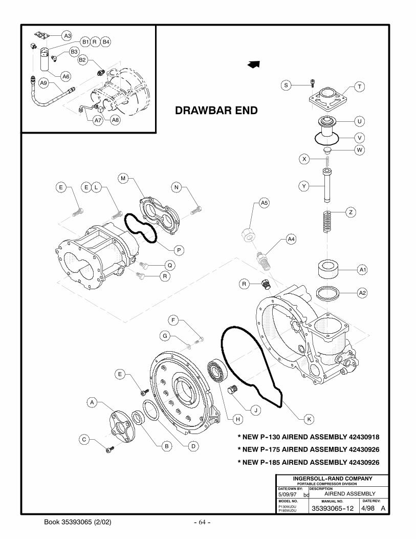
-- 64 --Book 35393065 (2/02)
DRAWBAR END
B
H
J
K
D
A2
A1
A5
A4
R
F
G
E
A
C
U
V
W
Z
X
S
Y
T
LE
M
N
P
Q
R
E
B3
B1
A8A7
P130WJDUP185WJDU
5/09/97
* NEW P--130 AIREND ASSEMBLY 42430918
* NEW P--175 AIREND ASSEMBLY 42430926
* NEW P--185 AIREND ASSEMBLY 42430926
AIREND ASSEMBLY
PORTABLE COMPRESSOR DIVISIONDESCRIPTION
MODEL NO.
INGERSOLL--RAND COMPANY
DATE/DWN BY:
bd
A9
B2
A3
A6
R B4
A35393065--12MANUAL NO.
4/98DATE/REV:
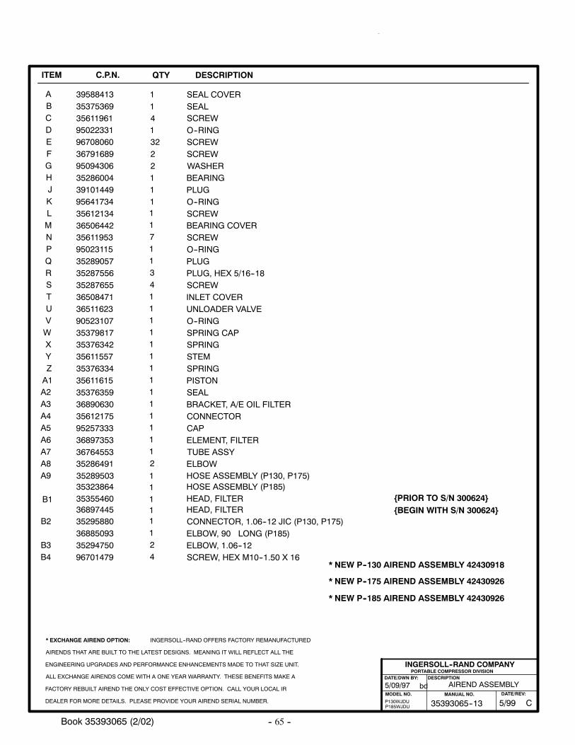
-- 65 --Book 35393065 (2/02)
ITEM C.P.N. QTY DESCRIPTION
ABCDEFGHJKLMNPQRSTUVWXYZA1A2A3A4A5A6A7A8A9
B1
3958841335375369356119619502233196708060367916899509430635286004391014499564173435612134365064423561195395023115352890573528755635287655365084713651162390523107353798173537634235611557353763343561161535376359368906303561217595257333368973533676455335286491
3532386435355460
114132221111171134111111111111112
11
SEAL COVERSEALSCREWO--RINGSCREWSCREWWASHERBEARINGPLUGO--RINGSCREWBEARING COVERSCREWO--RINGPLUGPLUG, HEX 5/16--18SCREWINLET COVERUNLOADER VALVEO--RINGSPRING CAPSPRINGSTEMSPRINGPISTONSEALBRACKET, A/E OIL FILTERCONNECTORCAPELEMENT, FILTERTUBE ASSYELBOW
HEAD, FILTER
AIREND ASSEMBLY
PORTABLE COMPRESSOR DIVISIONDESCRIPTION
MODEL NO.
INGERSOLL--RAND COMPANY
DATE/DWN BY:
bd
* EXCHANGE AIREND OPTION: INGERSOLL--RAND OFFERS FACTORY REMANUFACTURED
AIRENDS THAT ARE BUILT TO THE LATEST DESIGNS. MEANING IT WILL REFLECT ALL THE
ENGINEERING UPGRADES AND PERFORMANCE ENHANCEMENTS MADE TO THAT SIZE UNIT.
ALL EXCHANGE AIRENDS COME WITH A ONE YEAR WARRANTY. THESE BENEFITS MAKE A
FACTORY REBUILT AIREND THE ONLY COST EFFECTIVE OPTION. CALL YOUR LOCAL IR
DEALER FOR MORE DETAILS. PLEASE PROVIDE YOUR AIREND SERIAL NUMBER. P130WJDUP185WJDU
5/09/97
* NEW P--130 AIREND ASSEMBLY 42430918
* NEW P--175 AIREND ASSEMBLY 42430926
* NEW P--185 AIREND ASSEMBLY 42430926
B2
B3
35295880
35294750
1
2
CONNECTOR, 1.06--12 JIC (P130, P175)
ELBOW, 1.06--1236885093 1 ELBOW, 90 LONG (P185)
35289503 1 HOSE ASSEMBLY (P130, P175)HOSE ASSEMBLY (P185)
B4 96701479 4 SCREW, HEX M10--1.50 X 16
36897445 1 HEAD, FILTER BEGIN WITH S/N 300624PRIOR TO S/N 300624
C35393065--13MANUAL NO.
5/99DATE/REV:
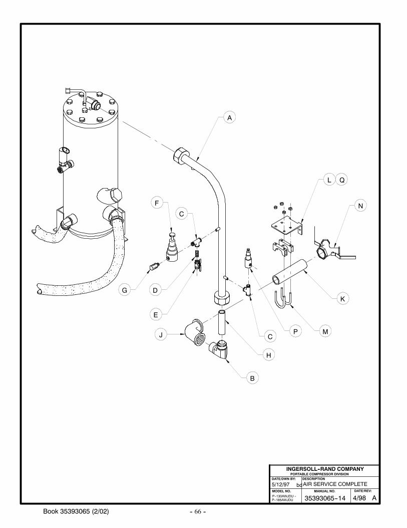
-- 66 --Book 35393065 (2/02)
AIR SERVICE COMPLETE
PORTABLE COMPRESSOR DIVISIONDESCRIPTION
MODEL NO.
INGERSOLL--RAND COMPANY
DATE/DWN BY:
bd5/12/97
P--185AWJDUP--130AWJDU --
A
L
N
K
MC
H
B
PJ
F
C
D
E
G
Q
A35393065--14MANUAL NO.
4/98DATE/REV:
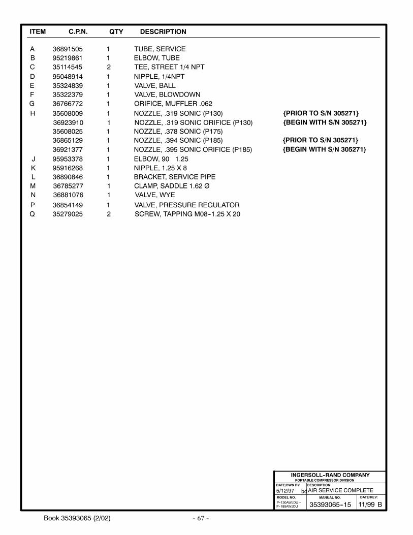
-- 67 --Book 35393065 (2/02)
ITEM C.P.N. QTY DESCRIPTION
ABCDE
95219861351145459504891435324839
1211
ELBOW, TUBETEE, STREET 1/4 NPTNIPPLE, 1/4NPTVALVE, BALL
35322379 1 VALVE, BLOWDOWN
36891505 1 TUBE, SERVICE
FG
H
JKLMN
PQ
36766772
9595337895916268
36785277
35608009
1
1
1
1
ORIFICE, MUFFLER .062
NIPPLE, 1.25 X 8
SCREW, TAPPING M08--1.25 X 20
NOZZLE, .319 SONIC (P130)
36890846
36854149
1
1
BRACKET, SERVICE PIPE
VALVE, PRESSURE REGULATOR
PORTABLE COMPRESSOR DIVISIONDESCRIPTION
MODEL NO.
INGERSOLL--RAND COMPANY
DATE/DWN BY:
bd
P--185AWJDUP--130AWJDU --
36881076 1 VALVE, WYE
35279025 2
CLAMP, SADDLE 1.62 Ø
AIR SERVICE COMPLETE5/12/97
35608025 1 NOZZLE, .378 SONIC (P175)36865129 1 NOZZLE, .394 SONIC (P185)
1 ELBOW, 90 1.25
B35393065--15MANUAL NO.
11/99DATE/REV:
36923910 1 NOZZLE, .319 SONIC ORIFICE (P130)
36921377 1 NOZZLE, .395 SONIC ORIFICE (P185)
BEGIN WITH S/N 305271PRIOR TO S/N 305271
BEGIN WITH S/N 305271PRIOR TO S/N 305271
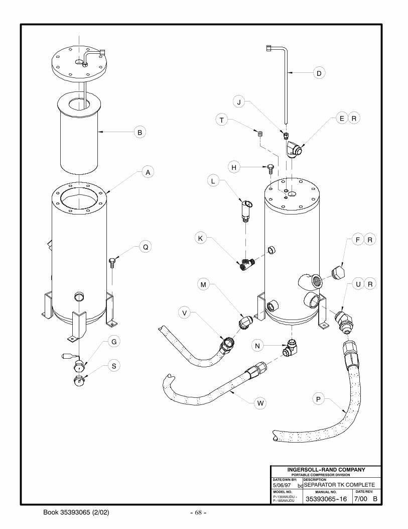
-- 68 --Book 35393065 (2/02)
SEPARATOR TK COMPLETE
PORTABLE COMPRESSOR DIVISIONDESCRIPTION
MODEL NO.
INGERSOLL--RAND COMPANY
DATE/DWN BY:
bd5/06/97
P--185AWJDUP--130AWJDU --
A
B
D
E
F
G
J
K
L
M
N
P
R
R
H
T
S
U R
Q
V
W
B35393065--16MANUAL NO.
7/00DATE/REV:
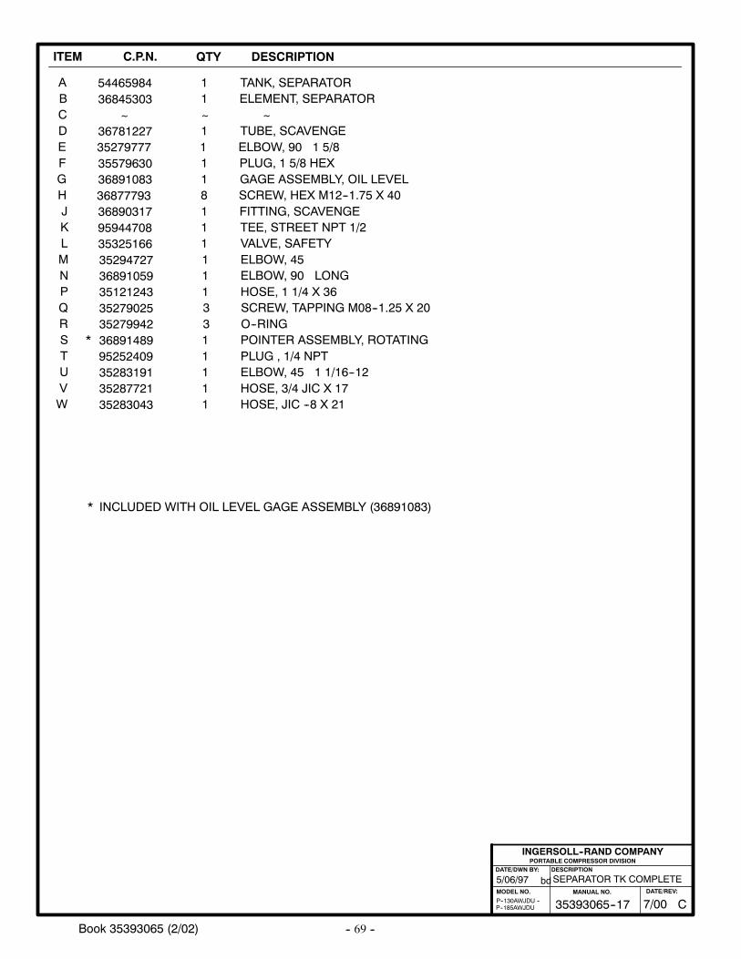
-- 69 --Book 35393065 (2/02)
ITEM C.P.N. QTY DESCRIPTION
ABCDE
36845303~
3678122735279777
1~11
ELEMENT, SEPARATOR~
TUBE, SCAVENGEELBOW, 90 1 5/8
35579630 1 PLUG, 1 5/8 HEX
54465984 1 TANK, SEPARATOR
FGHJKLMNPQ
36891083
3689031795944708
35294727
368777931
11
1
8GAGE ASSEMBLY, OIL LEVEL
FITTING, SCAVENGETEE, STREET NPT 1/2
ELBOW, 45
SCREW, HEX M12--1.75 X 40
35325166
35121243
1
1
VALVE, SAFETY
HOSE, 1 1/4 X 36
PORTABLE COMPRESSOR DIVISIONDESCRIPTION
MODEL NO.
INGERSOLL--RAND COMPANY
DATE/DWN BY:
bd
P--185AWJDUP--130AWJDU --
36891059 1 ELBOW, 90 LONG
35279025 3 SCREW, TAPPING M08--1.25 X 20
SEPARATOR TK COMPLETE5/06/97
R 35279942 3 O--RINGS 36891489 1 POINTER ASSEMBLY, ROTATINGT 95252409 1 PLUG , 1/4 NPTU 35283191 1 ELBOW, 45 1 1/16--12V 35287721 1 HOSE, 3/4 JIC X 17W 35283043 1 HOSE, JIC --8 X 21
*
* INCLUDED WITH OIL LEVEL GAGE ASSEMBLY (36891083)
C35393065--17MANUAL NO.
7/00DATE/REV:
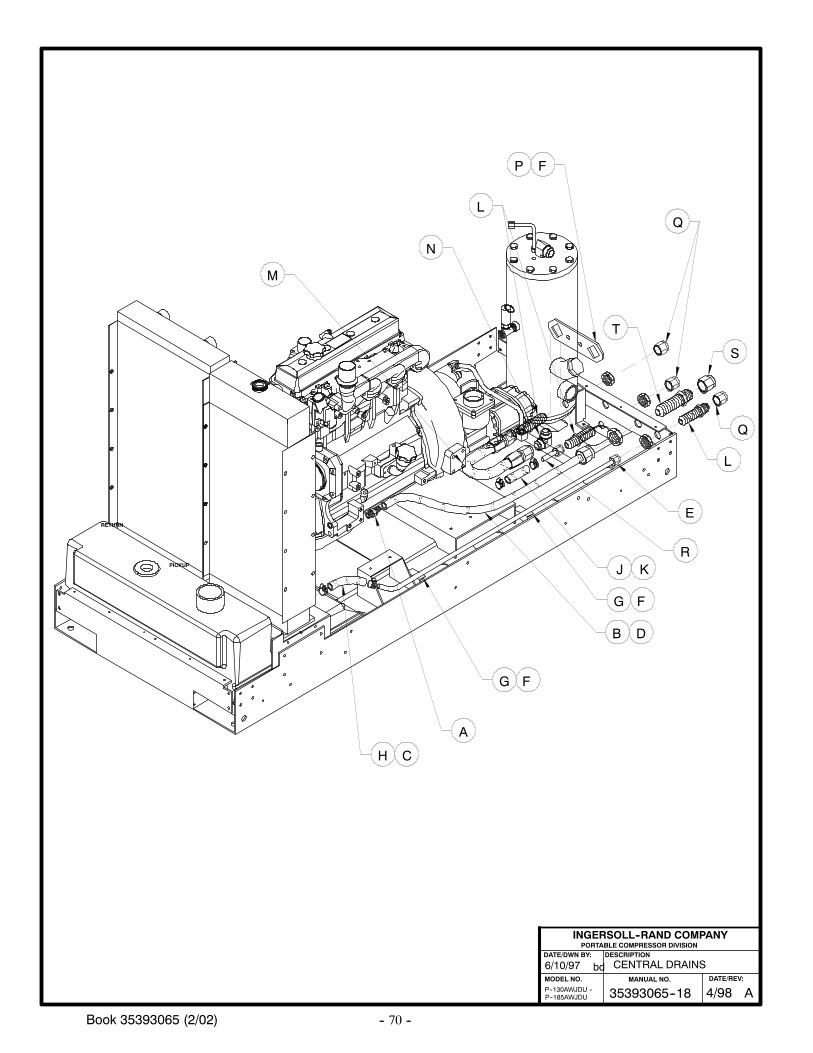
-- 70 --Book 35393065 (2/02)
CENTRAL DRAINS6/10/97
P--130AWJDU --P--185AWJDU
PORTABLE COMPRESSOR DIVISIONDESCRIPTION
MODEL NO.
INGERSOLL--RAND COMPANY
DATE/DWN BY:
bd
RETURN
PICKUP
A
D
G
B
H
G
F
C
F
E
JR
M
N
F
LQ
L
P
K
T
Q
S
A35393065--18MANUAL NO.
4/98DATE/REV:
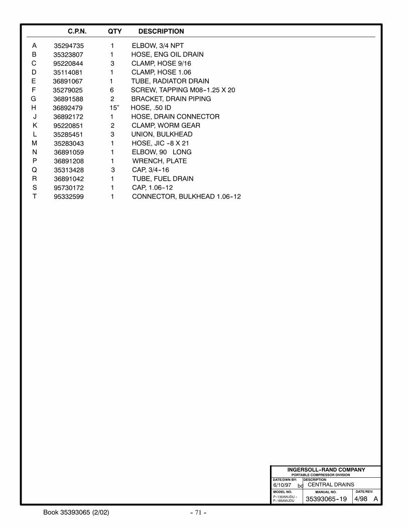
-- 71 --Book 35393065 (2/02)
C.P.N. QTY DESCRIPTION
ABCDE
9522084435323807
36891067
31
1
CLAMP, HOSE 9/16HOSE, ENG OIL DRAIN
TUBE, RADIATOR DRAIN
35294735 1 ELBOW, 3/4 NPT
FGHJKLMNPQ
36891588
9522085136892172
35283043
368924792
21
1
15”BRACKET, DRAIN PIPING
CLAMP, WORM GEARHOSE, DRAIN CONNECTOR
HOSE, JIC --8 X 21
HOSE, .50 ID
35285451
36891208
3
1
UNION, BULKHEAD
WRENCH, PLATE
PORTABLE COMPRESSOR DIVISIONDESCRIPTION
MODEL NO.
INGERSOLL--RAND COMPANY
DATE/DWN BY:
bd
P--185AWJDUP--130AWJDU --
36891059 1 ELBOW, 90 LONG
35279025 6 SCREW, TAPPING M08--1.25 X 20
R 36891042 1 TUBE, FUEL DRAIN35313428 3 CAP, 3/4--16
CENTRAL DRAINS6/10/97
ST 95332599 1 CONNECTOR, BULKHEAD 1.06--12
95730172 1 CAP, 1.06--12
35114081 1 CLAMP, HOSE 1.06
A35393065--19MANUAL NO.
4/98DATE/REV:
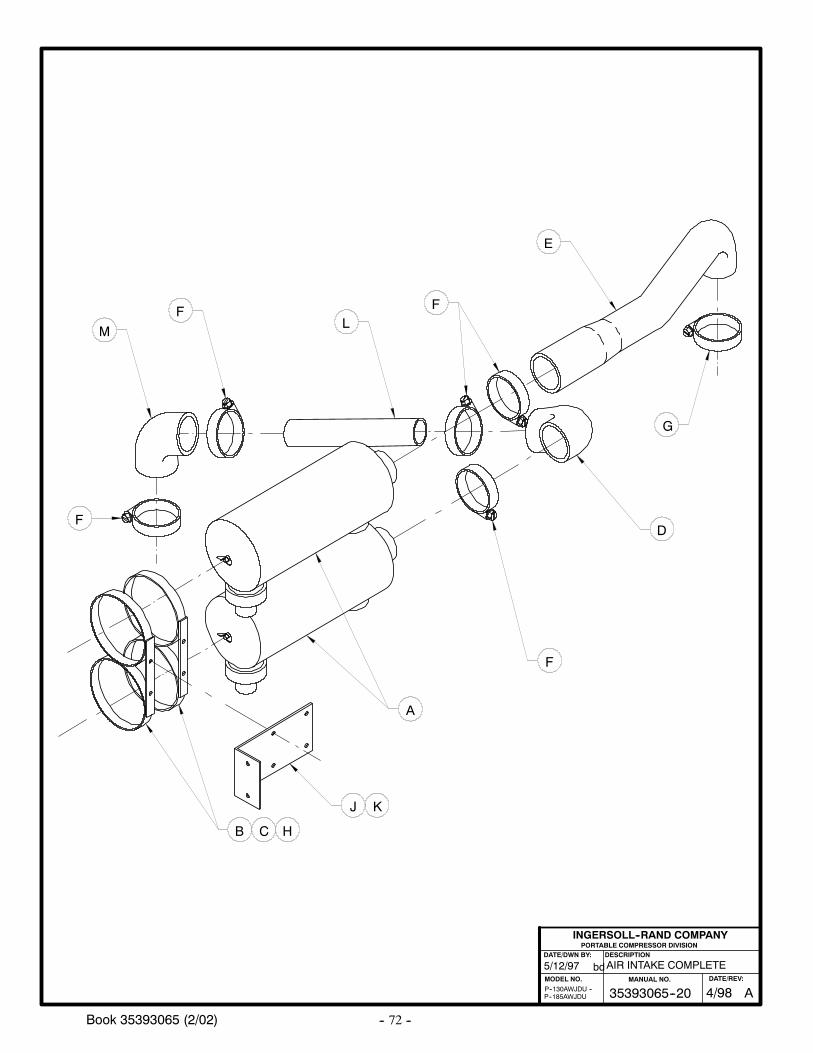
-- 72 --Book 35393065 (2/02)
AIR INTAKE COMPLETE
PORTABLE COMPRESSOR DIVISIONDESCRIPTION
MODEL NO.
INGERSOLL--RAND COMPANY
DATE/DWN BY:
bd5/12/97
P--185AWJDUP--130AWJDU --
A
B
D
E
F
G
F
C H
J K
LM
F
F
A35393065--20MANUAL NO.
4/98DATE/REV:
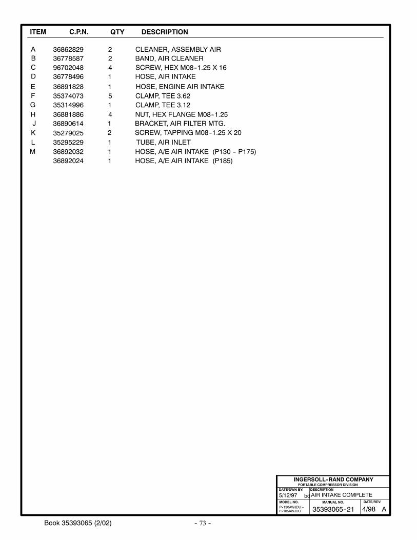
-- 73 --Book 35393065 (2/02)
ITEM C.P.N. QTY DESCRIPTION
ABCD
E
367785879670204836778496
36891828
241
1
BAND, AIR CLEANERSCREW, HEX M08--1.25 X 16HOSE, AIR INTAKE
HOSE, ENGINE AIR INTAKE35374073 5 CLAMP, TEE 3.62
36862829 2 CLEANER, ASSEMBLY AIR
FGH
3531499636881886
14
CLAMP, TEE 3.12NUT, HEX FLANGE M08--1.25
PORTABLE COMPRESSOR DIVISIONDESCRIPTION
MODEL NO.
INGERSOLL--RAND COMPANY
DATE/DWN BY:
bd
P--185AWJDUP--130AWJDU --
AIR INTAKE COMPLETE5/12/97
J 36890614 1 BRACKET, AIR FILTER MTG.K 35279025 2 SCREW, TAPPING M08--1.25 X 20L 35295229 1 TUBE, AIR INLET
36892032 1 HOSE, A/E AIR INTAKE (P130 -- P175)M36892024 1 HOSE, A/E AIR INTAKE (P185)
A35393065--21MANUAL NO.
4/98DATE/REV:
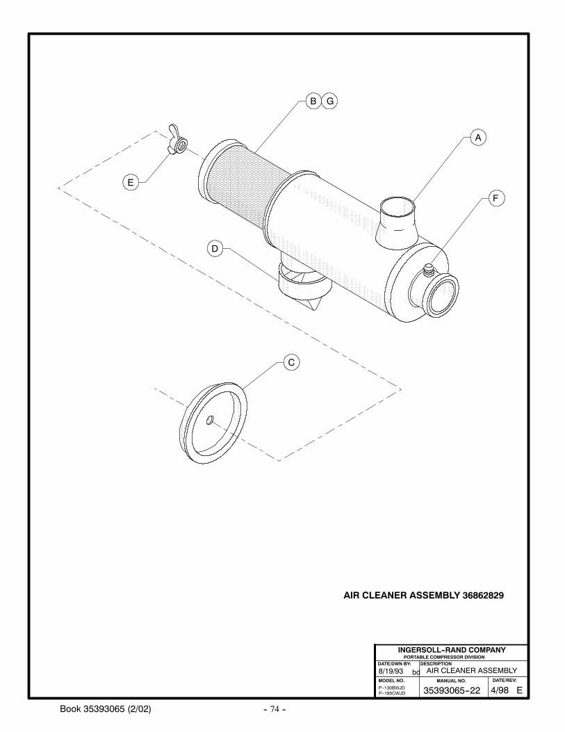
-- 74 --Book 35393065 (2/02)
AIR CLEANER ASSEMBLY 36862829
A
B
C
D
E
G
F
AIR CLEANER ASSEMBLY8/19/93
P--130BWJDP--185CWJD
PORTABLE COMPRESSOR DIVISIONDESCRIPTION
MODEL NO.
INGERSOLL--RAND COMPANY
DATE/DWN BY:
bd
E35393065--22MANUAL NO.
4/98DATE/REV:
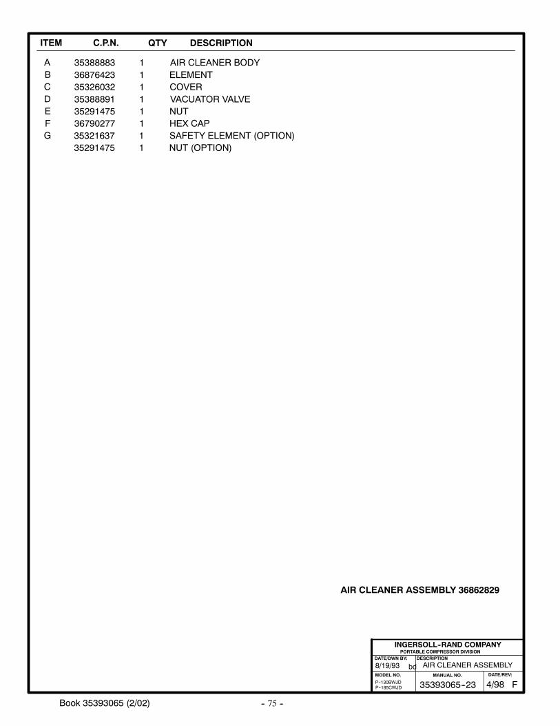
-- 75 --Book 35393065 (2/02)
ITEM C.P.N. QTY DESCRIPTION
AIR CLEANER ASSEMBLY 36862829
ABCDEFG
353888833687642335326032353888913529147536790277
111111
AIR CLEANER BODYELEMENTCOVERVACUATOR VALVENUT
35321637 1 SAFETY ELEMENT (OPTION)HEX CAP
35291475 1 NUT (OPTION)
AIR CLEANER ASSEMBLY8/19/93
P--130BWJDP--185CWJD
PORTABLE COMPRESSOR DIVISIONDESCRIPTION
MODEL NO.
INGERSOLL--RAND COMPANY
DATE/DWN BY:
bd
F35393065--23MANUAL NO.
4/98DATE/REV:
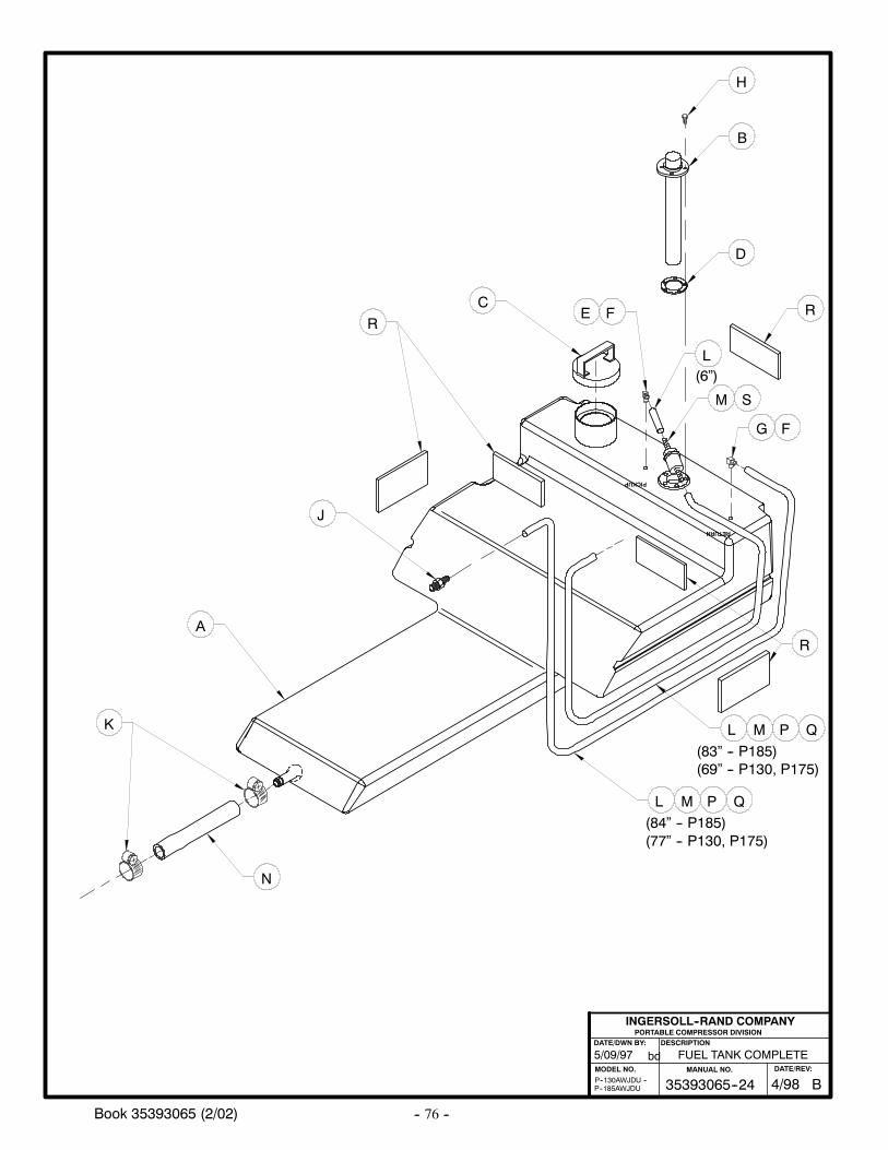
-- 76 --Book 35393065 (2/02)
PORTABLE COMPRESSOR DIVISIONDESCRIPTION
MODEL NO.
INGERSOLL--RAND COMPANY
DATE/DWN BY:
bd5/09/97
P--185AWJDUP--130AWJDU --
RETURN
PICKUP
FUEL TANK COMPLETE
A
C
H
B
L
D
M
N
K
J
G F
P Q
(84” -- P185)
(83” -- P185)
L M P Q
(69” -- P130, P175)
(77” -- P130, P175)
FER
R
R
M S
L(6”)
B35393065--24MANUAL NO.
4/98DATE/REV:
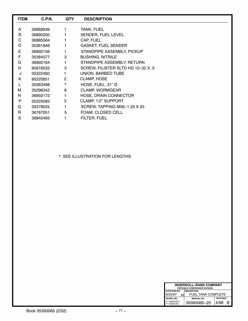
-- 77 --Book 35393065 (2/02)
ITEM C.P.N. QTY DESCRIPTION
ABCD
E
368902003688556435361849
36892156
111
1
SENDER, FUEL LEVELCAP, FUELGASKET, FUEL SENDER
STANDPIPE ASSEMBLY, PICKUP35384577 2 BUSHING, NITRILE
36889939 1 TANK, FUEL
FGH
3689216495916532
15
STANDPIPE ASSEMBLY, RETURNSCREW, FILISTER SLTD HD 10--32 X .5
PORTABLE COMPRESSOR DIVISIONDESCRIPTION
MODEL NO.
INGERSOLL--RAND COMPANY
DATE/DWN BY:
bd
P--185AWJDUP--130AWJDU --
6/25/97
J 35322460 1 UNION, BARBED TUBEK 95220851 2 CLAMP, HOSEL 35363498 * HOSE, FUEL .31” Ø
35296342 6 CLAMP, WORMGEARM36892172 1 HOSE, DRAIN CONNECTOR
FUEL TANK COMPLETE
NP 35225093 3 CLAMP, 1/2” SUPPORTQ 35279025 1 SCREW, TAPPING M08--1.25 X 20
* SEE ILLUSTRATION FOR LENGTHS
R 36767051 5 FOAM, CLOSED CELLS 36845493 1 FILTER, FUEL
B35393065--25MANUAL NO.
4/98DATE/REV:
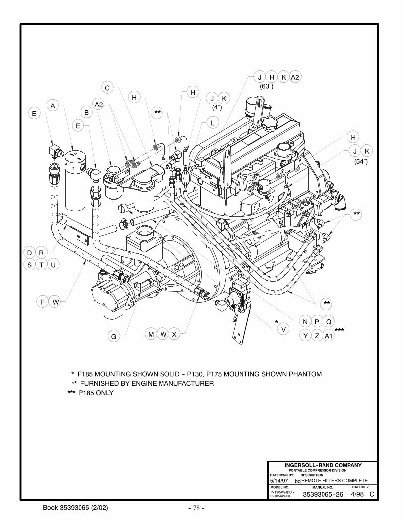
-- 78 --Book 35393065 (2/02)
GIN
E
OIL
L
PORTABLE COMPRESSOR DIVISIONDESCRIPTION
MODEL NO.
INGERSOLL--RAND COMPANY
DATE/DWN BY:
bd5/14/97
P--185AWJDUP--130AWJDU --
REMOTE FILTERS COMPLETE
**
**
X
J
EA
E
BA2
CH
**
HJ
L
K
K
R
W
H
N E
I
OEN
(54”)
(4”)
** FURNISHED BY ENGINE MANUFACTURER
D
TS
G
N P Q
U
J H(63”)
V*
* P185 MOUNTING SHOWN SOLID -- P130, P175 MOUNTING SHOWN PHANTOM
A2
W
F
M Y Z A1***
*** P185 ONLY
K
C35393065--26MANUAL NO.
4/98DATE/REV:
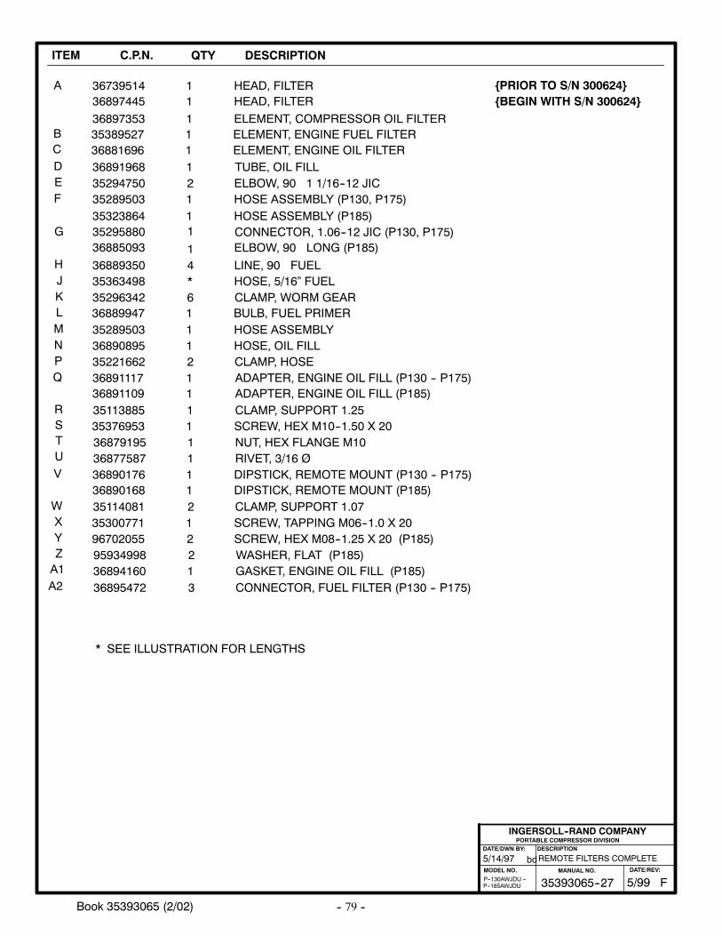
-- 79 --Book 35393065 (2/02)
ITEM C.P.N. QTY DESCRIPTION
A
BCDE
3689196835294750
12
TUBE, OIL FILLELBOW, 90 1 1/16--12 JIC
35289503 1 HOSE ASSEMBLY (P130, P175)
36739514 1 HEAD, FILTER
F
G
HJKLMNPQ
352963423536349836889350
6*4
CLAMP, WORM GEARHOSE, 5/16” FUELLINE, 90 FUEL
36889947
35221662
1
2
BULB, FUEL PRIMER
CLAMP, HOSE
PORTABLE COMPRESSOR DIVISIONDESCRIPTION
MODEL NO.
INGERSOLL--RAND COMPANY
DATE/DWN BY:
bd
P--185AWJDUP--130AWJDU --
36890895 1 HOSE, OIL FILL
36891117 1 ADAPTER, ENGINE OIL FILL (P130 -- P175)36891109 1 ADAPTER, ENGINE OIL FILL (P185)
35289503 1 HOSE ASSEMBLY
1
5/14/97 REMOTE FILTERS COMPLETE
3538952736881696
11
ELEMENT, ENGINE FUEL FILTERELEMENT, ENGINE OIL FILTER
36897353 1 ELEMENT, COMPRESSOR OIL FILTER
* SEE ILLUSTRATION FOR LENGTHS
R 35113885 1 CLAMP, SUPPORT 1.2535376953 1 SCREW, HEX M10--1.50 X 20S
TU 36877587 1
NUT, HEX FLANGE M1036879195 1RIVET, 3/16 Ø
V 36890176 1 DIPSTICK, REMOTE MOUNT (P130 -- P175)36890168 1 DIPSTICK, REMOTE MOUNT (P185)
35323864 1 HOSE ASSEMBLY (P185)35295880 1 CONNECTOR, 1.06--12 JIC (P130, P175)36885093 ELBOW, 90 LONG (P185)
W 35114081 2 CLAMP, SUPPORT 1.0735300771 1 SCREW, TAPPING M06--1.0 X 20X
96702055 2 SCREW, HEX M08--1.25 X 20 (P185)YZA1 36894160 1
WASHER, FLAT (P185)95934998 2GASKET, ENGINE OIL FILL (P185)
A2 CONNECTOR, FUEL FILTER (P130 -- P175)36895472 3
36897445 1 HEAD, FILTER BEGIN WITH S/N 300624PRIOR TO S/N 300624
F35393065--27MANUAL NO.
5/99DATE/REV:
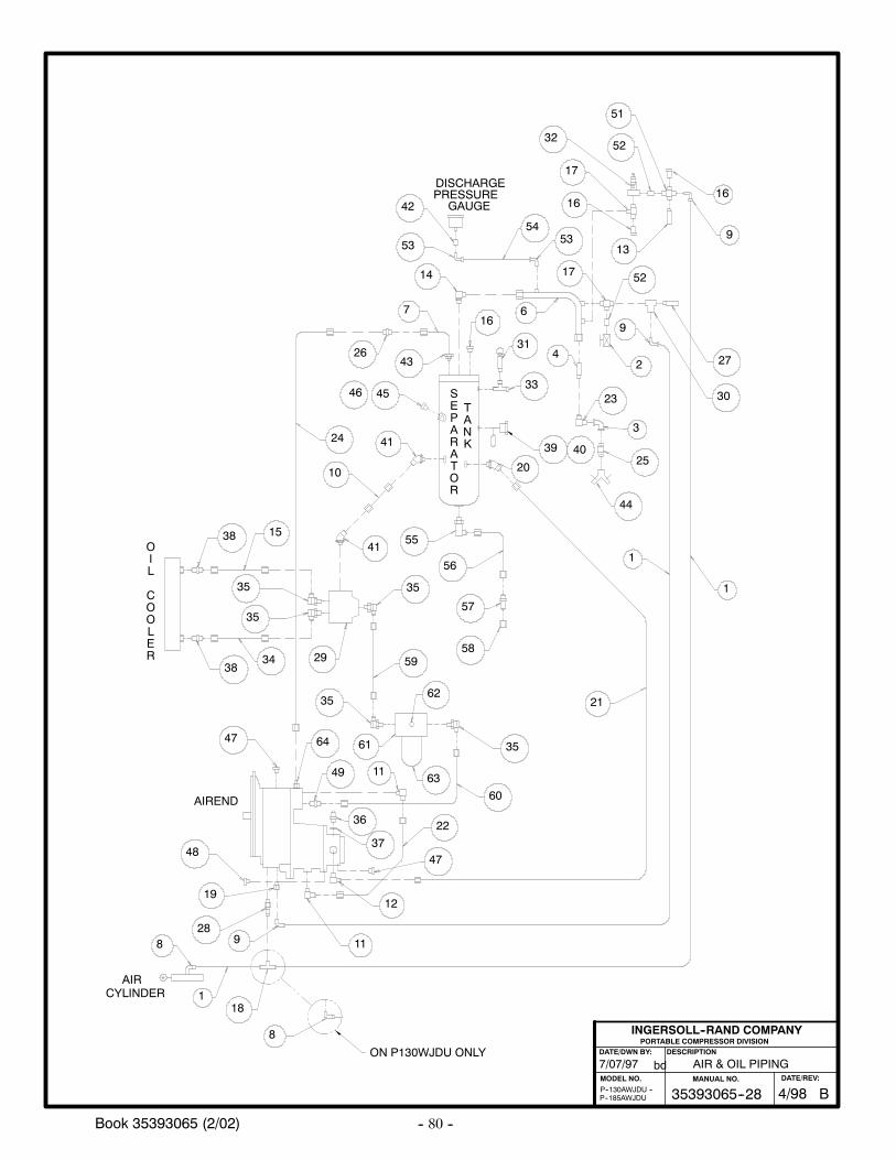
-- 80 --Book 35393065 (2/02)
AIR & OIL PIPING
PORTABLE COMPRESSOR DIVISIONDESCRIPTION
MODEL NO.
INGERSOLL--RAND COMPANY
DATE/DWN BY:
bd7/07/97
P--185AWJDUP--130AWJDU --
46
40
DISCHARGEPRESSURE
GAUGE
AIRCYLINDER
9
1
3
23
4
25
44
21
1
1
8
18
8 928
19
48
11
12
47
22
37
36
47
49
64
35
11
61
63
62
60
35
59
35
58
57
55
29
35
35
3438
153841
10
24
26
41
45
43
716
14
53
42
20
39
33
31
6
30
2
52
27
13
17
5354
16
17
3252
51
56
ON P130WJDU ONLY
AIREND
SEPARATOR
TANK
OIL
COOLER
9
16
B35393065--28MANUAL NO.
4/98DATE/REV:
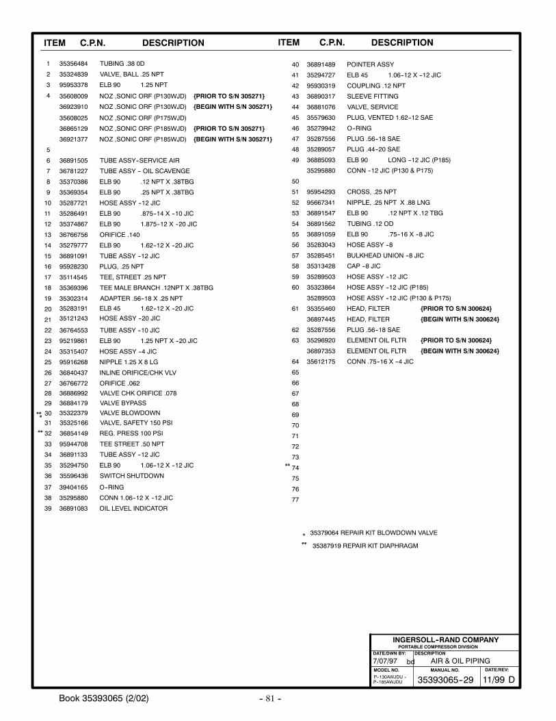
-- 81 --Book 35393065 (2/02)
ITEM C.P.N. DESCRIPTION ITEM C.P.N. DESCRIPTION
AIR & OIL PIPING
PORTABLE COMPRESSOR DIVISIONDESCRIPTION
MODEL NO.
INGERSOLL--RAND COMPANY
DATE/DWN BY:
bd
P--185AWJDUP--130AWJDU --
7/07/97
**
TUBE ASSY --10 JIC
ELB 90 .12 NPT X .12 TBG
CONN --12 JIC (P130 & P175)
ELB 90 LONG --12 JIC (P185)
PLUG .44--20 SAE
PLUG .56--18 SAE
PLUG, VENTED 1.62--12 SAE
COUPLING .12 NPT
SWITCH SHUTDOWN
ELB 90 1.06--12 X --12 JIC
ELB 90 1.25 NPT X --20 JIC
ELB 90 1.62--12 X --20 JIC
ELB 90 .25 NPT X .38TBG
ELB 90 .12 NPT X .38TBG
CONN .75--16 X --4 JIC35612175
ELEMENT OIL FLTR
36897353
72
71
70
69
68
67
66
65
64
63
PLUG .56--18 SAE35287556
HEAD, FILTER35355460
HOSE ASSY --12 JIC (P130 & P175)35289503
HOSE ASSY --12 JIC (P185)35323864
HOSE ASSY --12 JIC35289503
CAP --8 JIC35313428
BULKHEAD UNION --8 JIC35285451
HOSE ASSY --835283043
62
61
60
59
58
57
56
ELB 90 .75--16 X --8 JIC36891059
TUBING .12 OD36891562
36891547
35295880
36885093
O--RING35279942
SLEEVE FITTING36890317
ELB 45 1.06--12 X --12 JIC35294727
POINTER ASSY36891489
TUBE ASSY --12 JIC36891133
TEE STREET .50 NPT
35294750
36854149
95944708
3559643636
35
34
33
32
** 3532516631
VALVE CHK ORIFICE .078
30
29
28
HOSE ASSY --4 JIC
95219861
HOSE ASSY --20 JIC35121243
ELB 45 1.62--12 X --20 JIC35283191
ADAPTER .56--18 X .25 NPT
TEE MALE BRANCH .12NPT X .38TBG
TEE, STREET .25 NPT
TUBE ASSY --12 JIC36891091
ELB 90 1.875--12 X --20 JIC
ELB 90 .875--14 X --10 JIC
HOSE ASSY --12 JIC
TUBE ASSY -- OIL SCAVENGE
TUBE ASSY--SERVICE AIR36891505
36886992
35374867
36884179
35315407
35287721
55
*
*
**
35387919 REPAIR KIT DIAPHRAGM
ELB 90 1.25 NPT
NIPPLE 1.25 X 8 LG95916268
50
54
53
52
51
NIPPLE, .25 NPT X .88 LNG95667341
CROSS, .25 NPT9595429335369354
35286491
35114545
35302314
35579630
35287556
35289057
36766772 ORIFICE .062
35324839
36781227
35370386
35279777
PLUG, .25 NPT
36881076 VALVE, SERVICE
353564841
2
3
4
5
6
7
8
9
10
11
12
13
14
15
16
17
18
19
20
21
22
23
24
25
26
27
40
41
42
43
45
46
48
44
47
TUBING .38 0D
35369396
VALVE BYPASS
35322379 VALVE BLOWDOWN
VALVE, BALL .25 NPT
36766756 ORIFICE .140
95928230
INLINE ORIFICE/CHK VLV
36764553
95930319
49
35379064 REPAIR KIT BLOWDOWN VALVE
95953378
36840437
35608009 NOZ ,SONIC ORF (P130WJD)
35608025 NOZ ,SONIC ORF (P175WJD)
36865129 NOZ ,SONIC ORF (P185WJD)
REG. PRESS 100 PSI
VALVE, SAFETY 150 PSI
OIL LEVEL INDICATOR
CONN 1.06--12 X --12 JIC
O--RING39404165
35295880
3689108339
38
37
73
74
75
76
77
**
ELEMENT OIL FLTR
35296920
HEAD, FILTER36897445 BEGIN WITH S/N 300624
PRIOR TO S/N 300624
D35393065--29MANUAL NO.
11/99DATE/REV:
BEGIN WITH S/N 300624
PRIOR TO S/N 300624
36923910 NOZ ,SONIC ORF (P130WJD)
36921377 NOZ ,SONIC ORF (P185WJD)
BEGIN WITH S/N 305271
PRIOR TO S/N 305271
BEGIN WITH S/N 305271
PRIOR TO S/N 305271
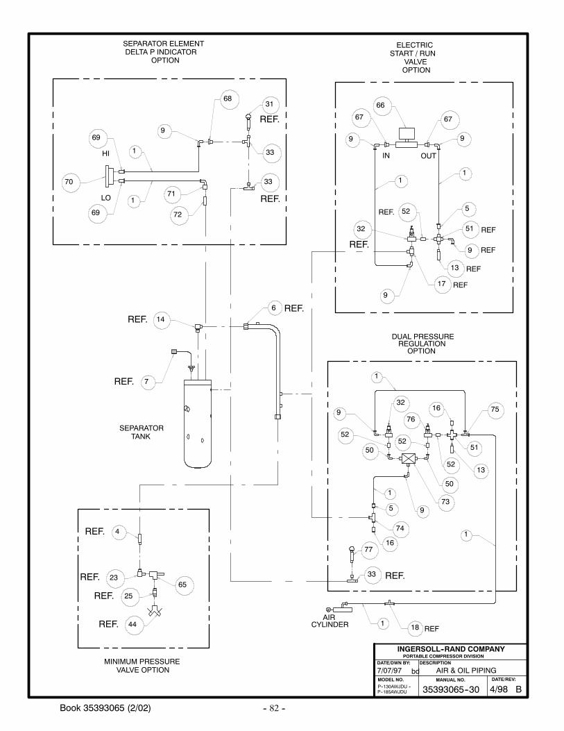
-- 82 --Book 35393065 (2/02)
AIR & OIL PIPING
PORTABLE COMPRESSOR DIVISIONDESCRIPTION
MODEL NO.
INGERSOLL--RAND COMPANY
DATE/DWN BY:
bd7/07/97
P--185AWJDUP--130AWJDU --
OUTIN
ELECTRICSTART / RUN
VALVEOPTION
HI
LO
SEPARATOR ELEMENTDELTA P INDICATOR
OPTION
MINIMUM PRESSUREVALVE OPTION
1
1
23
25
44
4
65
14
7
33
66
9
67 67
9
1
5
51 REF
9 REF
13 REF
17 REF
52
32
9
33
3168
9
1
69
70
69
71
72
REF.
REF.
REF.
REF.
REF.
REF.
REF.
REF.
REF.
DUAL PRESSUREREGULATION
OPTION
AIRCYLINDER
50
9
5213
51
16 75
52
76
329
52
50
16
74
5
18 REF
1
1
1
73
SEPARATORTANK
1
33 REF.
REF.
6 REF.
77
B35393065--30MANUAL NO.
4/98DATE/REV:
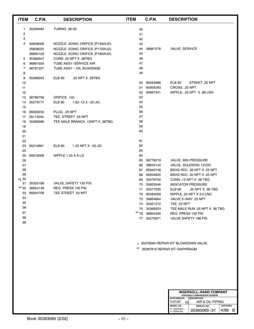
-- 83 --Book 35393065 (2/02)
ITEM C.P.N. DESCRIPTION ITEM C.P.N. DESCRIPTION
AIR & OIL PIPING
PORTABLE COMPRESSOR DIVISIONDESCRIPTION
MODEL NO.
INGERSOLL--RAND COMPANY
DATE/DWN BY:
bd
P--185AWJDUP--130AWJDU --
7/07/97
**ELB 90 1.25 NPT X --20 JIC
ELB 90 1.62--12 X --20 JIC
ELB 90 .25 NPT X .38TBG
CONN .25 NPT X .38TBG
NIPPLE .25 NPT X 3.0 LNG95084059
ELB 90 .25 NPT X .38 TBG35377035
INDICATOR PRESSURE35825546
CONN .12 NPT X .38 TBG35379700
BSHG RDC .50 NPT X .25 NPT95944625
BSHG RDC .38 NPT X .25 NPT95940748
VALVE, SOLENOID 12VDC36843142
VALVE, MIN PRESSURE36776219
72
71
70
69
68
67
66
65
64
63
62
61
60
59
58
57
56
TEE STREET .50 NPT
36854149
95944708
36
35
34
33
32
** 3532516631302928
95219861
TEE MALE BRANCH .12NPT X .38TBG
TEE, STREET .25 NPT
TUBE ASSY -- OIL SCAVENGE
TUBE ASSY--SERVICE AIR36891505
55
*
***
35387919 REPAIR KIT DIAPHRAGM
NIPPLE 1.25 X 8 LG95916268
50
54
53
52
51
NIPPLE, .25 NPT X .88 LNG95667341
CROSS, .25 NPT95954293
35369354
35114545
36781227
35279777
PLUG, .25 NPT
36881076 VALVE, SERVICE
353564841
2
3
4
5
6
7
8
9
10
11
12
13
14
15
16
17
18
19
20
21
22
23
24
25
26
27
40
41
42
43
45
46
48
44
47
TUBING .38 0D
35369396
36766756 ORIFICE .140
95928230
49
35379064 REPAIR KIT BLOWDOWN VALVE
35369347
35608009 NOZZLE ,SONIC ORIFICE (P130WJD)
35608025 NOZZLE ,SONIC ORIFICE (P175WJD)
36865129 NOZZLE ,SONIC ORIFICE (P185WJD)
REG. PRESS 100 PSI
VALVE, SAFETY 150 PSI
95944666 ELB 90 STREET .25 NPT
39
38
37
73
74
75
76
77
36864684 VALVE 3--WAY .25 NPT
35321272 TEE .25 NPT
35369503 TEE MALE RUN .25 NPT X .38 TBG
36854495
35375971 VALVE SAFETY 188 PSI
REG. PRESS 150 PSI
**
B35393065--31MANUAL NO.
4/98DATE/REV:
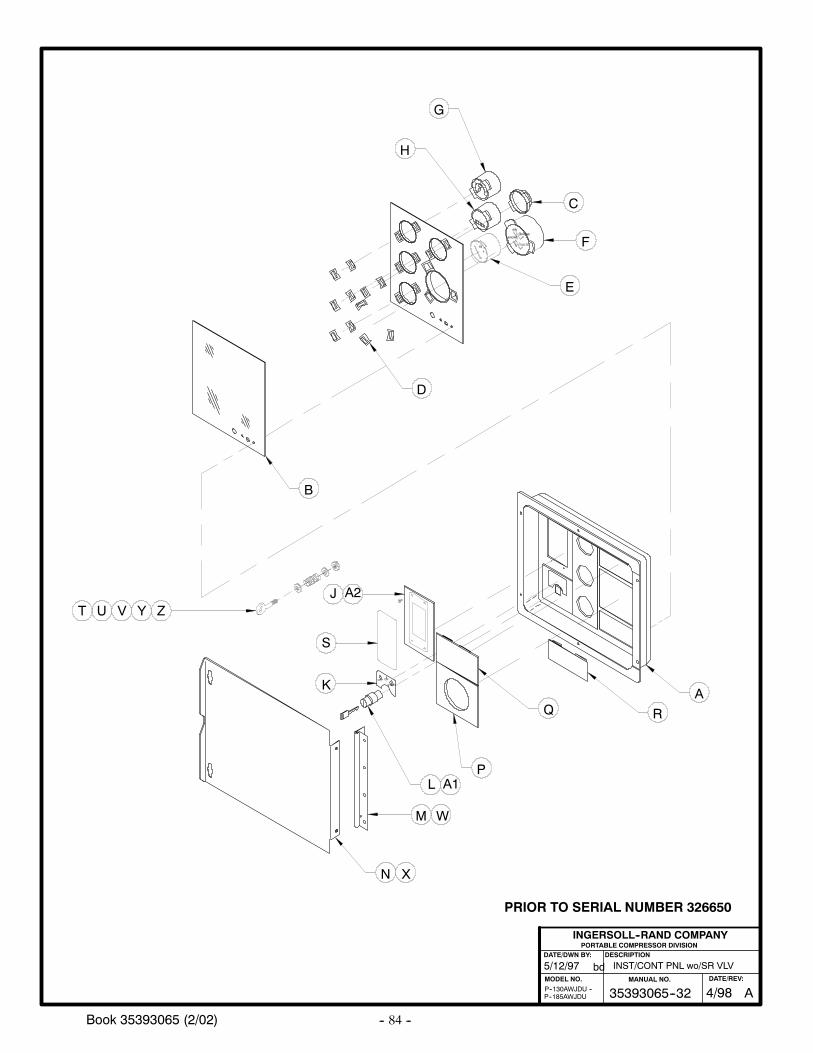
-- 84 --Book 35393065 (2/02)
OFF ON
START
F
E
B
D
P
G
H
C
ENGINEENGINE
VOLTS
AIR
1/2
1
A
R
INST/CONT PNL wo/SR VLV
PORTABLE COMPRESSOR DIVISIONDESCRIPTION
MODEL NO.
INGERSOLL--RAND COMPANY
DATE/DWN BY:
bd
L A1
5/12/97
P--185AWJDUP--130AWJDU --
M
N
A2
X
ZYVUT
K
S
J
Q
W
A35393065--32MANUAL NO.
4/98DATE/REV:
PRIOR TO SERIAL NUMBER 326650
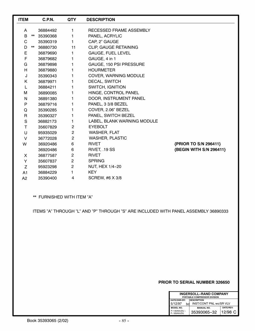
-- 85 --Book 35393065 (2/02)
ITEM C.P.N. QTY DESCRIPTION
ABCDEFGHJKLMNPQRSTUVW
X
3688449235390368
3688073036879690368796823687989836879880
3688421136879971
36879716
35390327
1111111111111
111
RECESSED FRAME ASSEMBLYPANEL, ACRYLIC
CLIP, GAUGE RETAININGGAUGE, FUEL LEVELGAUGE, 4 in 1GAUGE, 150 PSI PRESSUREHOURMETER
DECAL, SWITCHSWITCH, IGNITION
PANEL, 3 3/8 BEZEL
PANEL, SWITCH BEZEL1
YZA1
INST/CONT PNL wo/SR VLV
PORTABLE COMPRESSOR DIVISIONDESCRIPTION
MODEL NO.
INGERSOLL--RAND COMPANY
DATE/DWN BY:
bd5/12/97
P--185AWJDUP--130AWJDU --
**
**
** FURNISHED WITH ITEM ”A”
ITEMS ”A” THROUGH ”L” AND ”P” THROUGH ”S” ARE INCLUDED WITH PANEL ASSEMBLY 36890333
35390319 CAP, 2” GAUGE
35390343 COVER, WARNING MODULE
36890085 HINGE, CONTROL PANEL
35390400 4 SCREW, #6 X 3/8
36891380 DOOR, INSTRUMENT PANEL1
35390285 COVER, 2.06” BEZEL
36882173 LABEL, BLANK WARNING MODULE
A2
36920486
36877587
6
2
RIVET
RIVET
356078299593502936772028
3560783795923298
222
22
EYEBOLTWASHER, FLATWASHER, PLASTIC
SPRINGNUT, HEX 1/4--20
36884229 1 KEY
36920486 6 RIVET, .19 SS BEGIN WITH S/N 296411PRIOR TO S/N 296411
C35393065--32MANUAL NO.
12/98DATE/REV:
PRIOR TO SERIAL NUMBER 326650
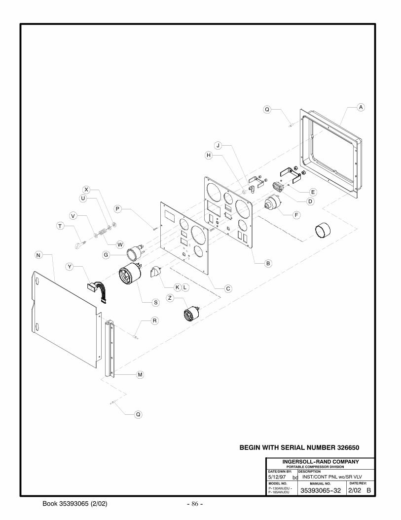
-- 86 --Book 35393065 (2/02)
INST/CONT PNL wo/SR VLV
PORTABLE COMPRESSOR DIVISIONDESCRIPTION
MODEL NO.
INGERSOLL--RAND COMPANY
DATE/DWN BY:
bd5/12/97
P--185AWJDUP--130AWJDU --
X
W
V
U
T
B35393065--32MANUAL NO.
2/02DATE/REV:
A
B
C
E
D
F
G
K
R
M
Q
Q
J
H
P
L
S
N
BEGIN WITH SERIAL NUMBER 326650
Y
Z
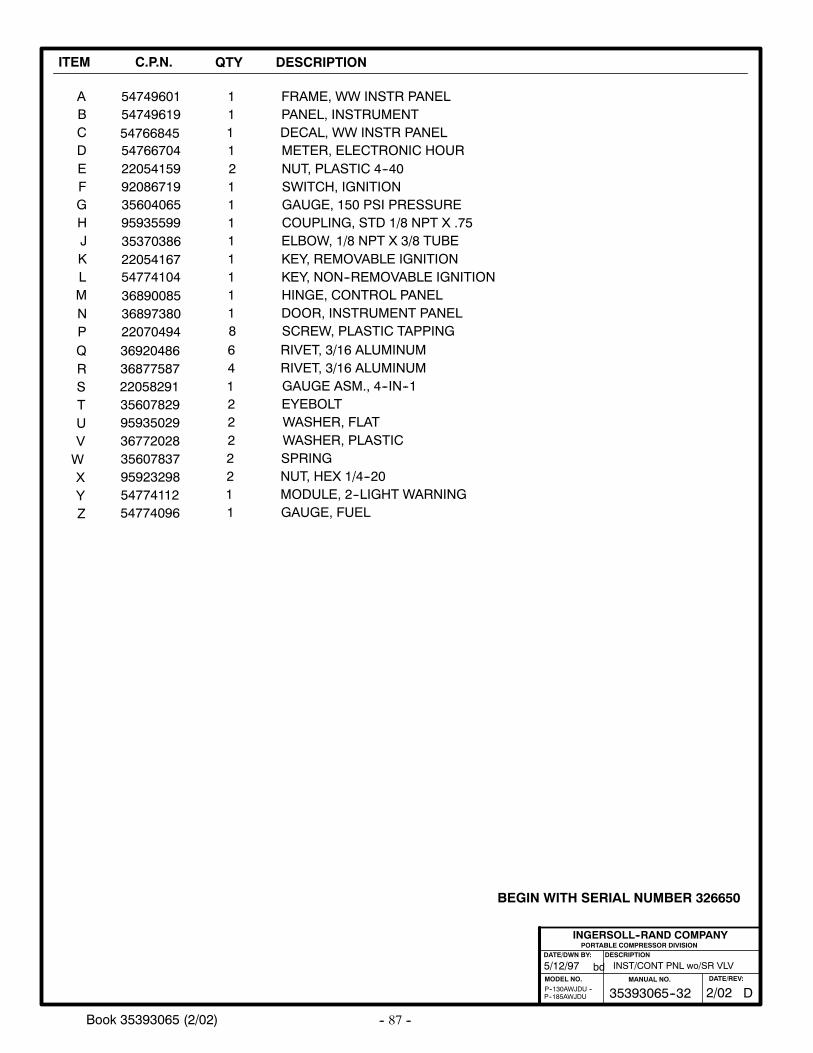
-- 87 --Book 35393065 (2/02)
ITEM C.P.N. QTY DESCRIPTION
INST/CONT PNL wo/SR VLV
PORTABLE COMPRESSOR DIVISIONDESCRIPTION
MODEL NO.
INGERSOLL--RAND COMPANY
DATE/DWN BY:
bd5/12/97
P--185AWJDUP--130AWJDU -- D35393065--32
MANUAL NO.
2/02DATE/REV:
BEGIN WITH SERIAL NUMBER 326650
ABCDEFGHJKLMNPQR
5474960154749619
5476670422054159920867193560406595935599
54774104
3537038622054167
36890085368973802207049436920486
11
121111111186
FRAME, WW INSTR PANELPANEL, INSTRUMENT
METER, ELECTRONIC HOURNUT, PLASTIC 4--40SWITCH, IGNITIONGAUGE, 150 PSI PRESSURECOUPLING, STD 1/8 NPT X .75ELBOW, 1/8 NPT X 3/8 TUBEKEY, REMOVABLE IGNITIONKEY, NON--REMOVABLE IGNITIONHINGE, CONTROL PANELDOOR, INSTRUMENT PANELSCREW, PLASTIC TAPPINGRIVET, 3/16 ALUMINUM
54766845 1 DECAL, WW INSTR PANEL
36877587 4 RIVET, 3/16 ALUMINUMSTUVWX
1
YZ 54774096 1 GAUGE, FUEL
22058291 GAUGE ASM., 4--IN--13560782995935029367720283560783795923298
22222
EYEBOLTWASHER, FLATWASHER, PLASTICSPRINGNUT, HEX 1/4--20
54774112 1 MODULE, 2--LIGHT WARNING
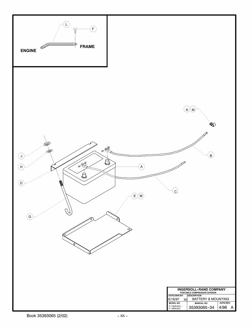
-- 88 --Book 35393065 (2/02)
ENGINEFRAME
FL
E
AH
J
D
G
6/16/97
P--185WJDUP--130WJDU --
B
C
M
BATTERY & MOUNTING
PORTABLE COMPRESSOR DIVISIONDESCRIPTION
MODEL NO.
INGERSOLL--RAND COMPANY
DATE/DWN BY:
bd
M
K
A35393065--34MANUAL NO.
4/98DATE/REV:
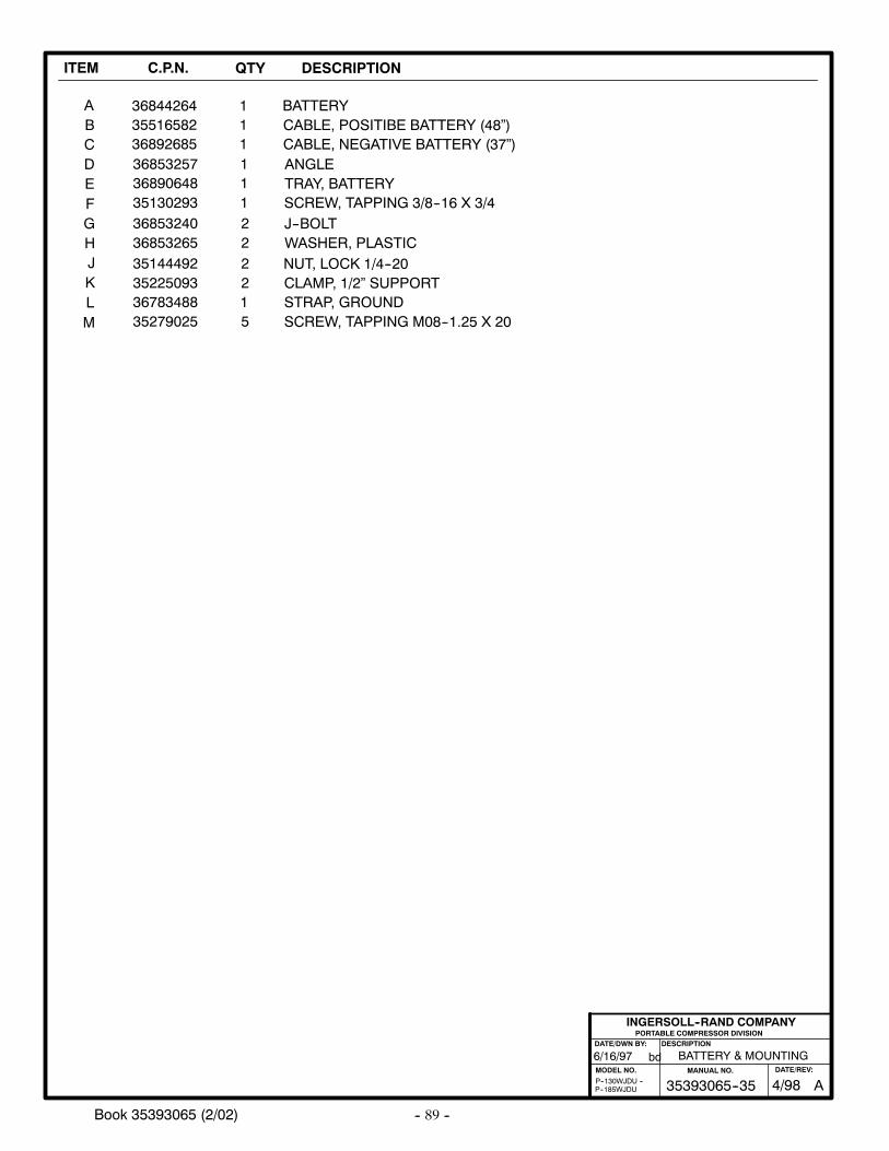
-- 89 --Book 35393065 (2/02)
ITEM C.P.N. QTY DESCRIPTION
ABCDEFGHJKL
3684426435516582368926853685325736890648
3685324036853265351444923522509336783488
35130293
11111
22221
1
BATTERYCABLE, POSITIBE BATTERY (48”)CABLE, NEGATIVE BATTERY (37”)ANGLETRAY, BATTERY
J--BOLTWASHER, PLASTICNUT, LOCK 1/4--20CLAMP, 1/2” SUPPORTSTRAP, GROUND
SCREW, TAPPING 3/8--16 X 3/4
BATTERY & MOUNTING
PORTABLE COMPRESSOR DIVISIONDESCRIPTION
MODEL NO.
INGERSOLL--RAND COMPANY
DATE/DWN BY:
bd6/16/97
P--185WJDUP--130WJDU --
M 35279025 5 SCREW, TAPPING M08--1.25 X 20
A35393065--35MANUAL NO.
4/98DATE/REV:
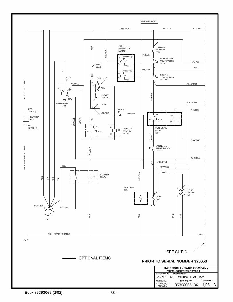
-- 90 --Book 35393065 (2/02)
6/19/97
P--185WJDUP--130WJDU --
WIRING DIAGRAM
PORTABLE COMPRESSOR DIVISIONDESCRIPTION
MODEL NO.
INGERSOLL--RAND COMPANY
DATE/DWN BY:
bd
YEL/GRY
VIO/YEL
ORN/BLK
RED
RED
RED
RED
RED
RED/YEL
RED
STARTERRELAYK1
STARTERPROTECTRELAY
YEL/RED
DIODED1
GRY/RED
ALTERNATORG1
VIO/YEL
VIO/YEL
R/W
(+)
(--)
GRY/RED
BRN
D+
ENGINETEMP SWITCHS4 N.C.
COMPRESSORTEMP SWITCHS2 N.C.
LT BLU/ORG
RED/BLK
RED/BLK
LT BLU
12
87
GRY/BLU
86
BATTERYCABLE
--BLA
CK
30
START
RUN
OFF
BATTERYCABLE
--RED
RED
RED
GRY
FUELSOLL1
THERMALSENSORTS1
NEG12VDC (--)
POS12VDC (+)
YEL
PNK/VIO
PNK/GRN
STARTERB1
HOURMETERM5
STARTSW S1
K2
85
S
S
IB
87A
BATTB+
BATTERYBT1
PNK/BLU
PNK/BLK
LT BLU/RED
ORN/BLK
RED/BLKRED/BLK
BRN -- 12VDC NEGATIVE
AIR
AIR
GENERATOR OPT.
START/RUNSOLL2
RED/ORN
PNK/BLK
86
85
87A
30
87
ENGINE OILPRESS SWITCHS3 N.O.
FUEL LEVELRELAYK3
AIR/GENERATORLOAD S8
LT BLU/RED
GRY/WHT
BRN
BRN
BRN
BRN
WARMUP(T)
WARMUP(T)
GEN(B)
GEN(B)
LFT
(C)
RT
(C)
FUSE30A F1
SEE SHT. 3
OPTIONAL ITEMS
A35393065--36MANUAL NO.
4/98DATE/REV:
PRIOR TO SERIAL NUMBER 326650
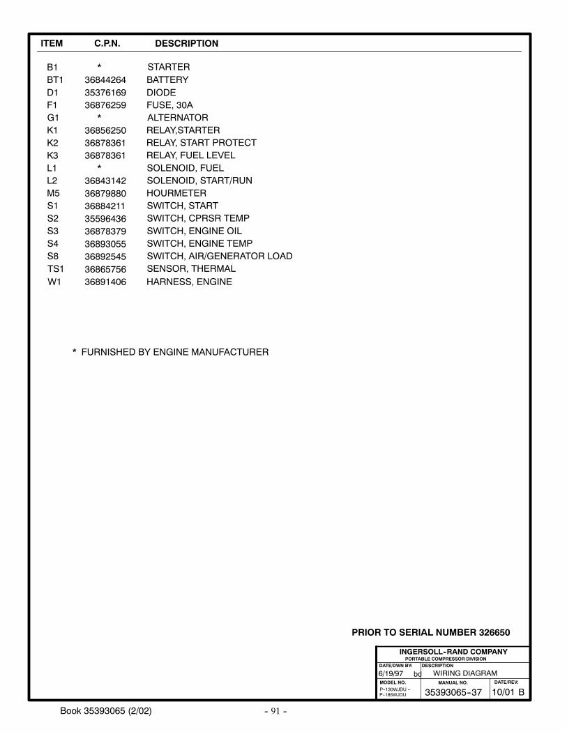
-- 91 --Book 35393065 (2/02)
ITEM C.P.N. DESCRIPTION
B1 STARTERBT1D1F1G1K1K2
L1
M5S1S2S3S4
TS1
BATTERYDIODEFUSE, 30AALTERNATORRELAY,STARTERRELAY, START PROTECT
SOLENOID, FUEL
HOURMETERSWITCH, STARTSWITCH, CPRSR TEMPSWITCH, ENGINE OILSWITCH, ENGINE TEMP
SENSOR, THERMALW1 HARNESS, ENGINE
*
*
*
* FURNISHED BY ENGINE MANUFACTURER
36891406
35596436
36893055
3687836136856250
3688421136879880
368442643537616936876259
36878379
36865756
PORTABLE COMPRESSOR DIVISIONDESCRIPTION
MODEL NO.
INGERSOLL--RAND COMPANY
DATE/DWN BY:
bd6/19/97
P--185WJDUP--130WJDU --
WIRING DIAGRAM
S8 SWITCH, AIR/GENERATOR LOAD36892545
K3
L2
RELAY, FUEL LEVEL
SOLENOID, START/RUN36843142
36878361
B35393065--37MANUAL NO.
10/01DATE/REV:
PRIOR TO SERIAL NUMBER 326650
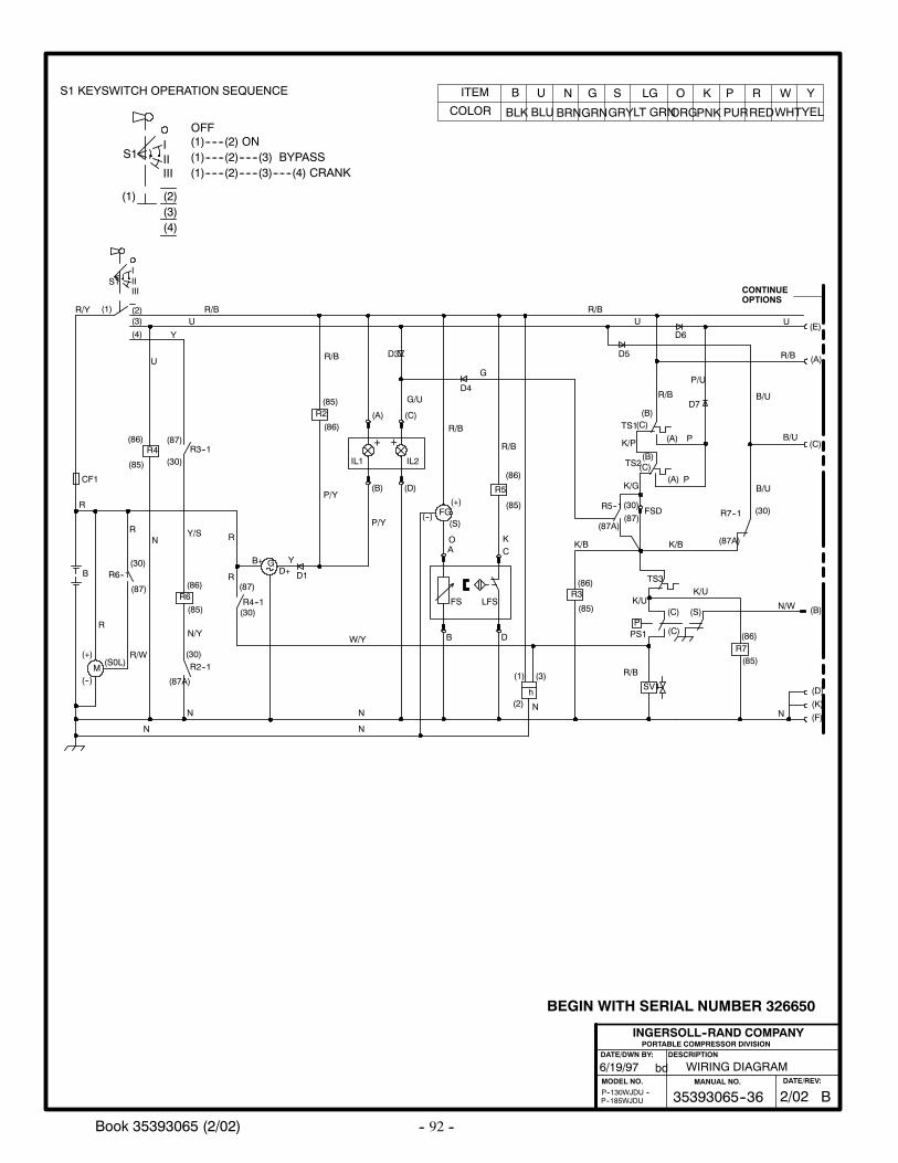
-- 92 --Book 35393065 (2/02)
6/19/97
P--185WJDUP--130WJDU --
WIRING DIAGRAM
PORTABLE COMPRESSOR DIVISIONDESCRIPTION
MODEL NO.
INGERSOLL--RAND COMPANY
DATE/DWN BY:
bd
B35393065--36MANUAL NO.
2/02DATE/REV:
BEGIN WITH SERIAL NUMBER 326650
ITEM
COLOR
B
BLK
U
BLU
N
BRN
G
GRN
S
GRY
LG
LT GRN
O
ORG
K
PNK
P
PUR
R
RED
W
WHT
Y
YEL
M
(2)(3)
(4)
B
(+)
(--)
R6--1
(S0L)
CF1
R3--1
G
S1
(1)
R
B+D+
(87)
(30)
(87)
(30)
(86)
(85)
R4--1
(87)
(30)
R6(86)
(85)
(30)R2--1
(87A)
R4
R/Y
U
Y
UR/B
R
R
R/W
NY/S
N/Y
N
N
R
R
IIIIII
N
N
W/Y
UR/B
D1
P/Y
P/Y
SV1
TS1
TS3
R2
h
(3)
(86)
(85)
TS2
P
(85)
(86)R3
PS1
R/B
N
R/B
K/P
K/G
K/UN/W
G
P
U
(B)(C)
(B)(C)
(A)
(A)
(C)
(C)
(S)
D3
D4
(F)N
(B)
K/U
P
(1) R/B
(C)
(2)
R/B (A)
(E)
CONTINUEOPTIONS
K/B
FSD
Y
(A)
(B)
IL1
+
IL2
+
(C)
(D)
LFS
R5
B
(86)
(85)
D
FS
FG(+)
(--)(S)
A CO K
R/B
R/B
(85)
(86)R7
G/U
D5
D6
D7
R5--1(30)
(87A)(87)
B/U
(30)R7--1
(87A)K/B
(K)
(D)
P/U
B/U
B/U
OFF
(1) (2)(3)(4)
(1)------(2) ON
(1)------(2)------(3)------(4) CRANK(1)------(2)------(3) BYPASSS1
IIIIII
S1 KEYSWITCH OPERATION SEQUENCE
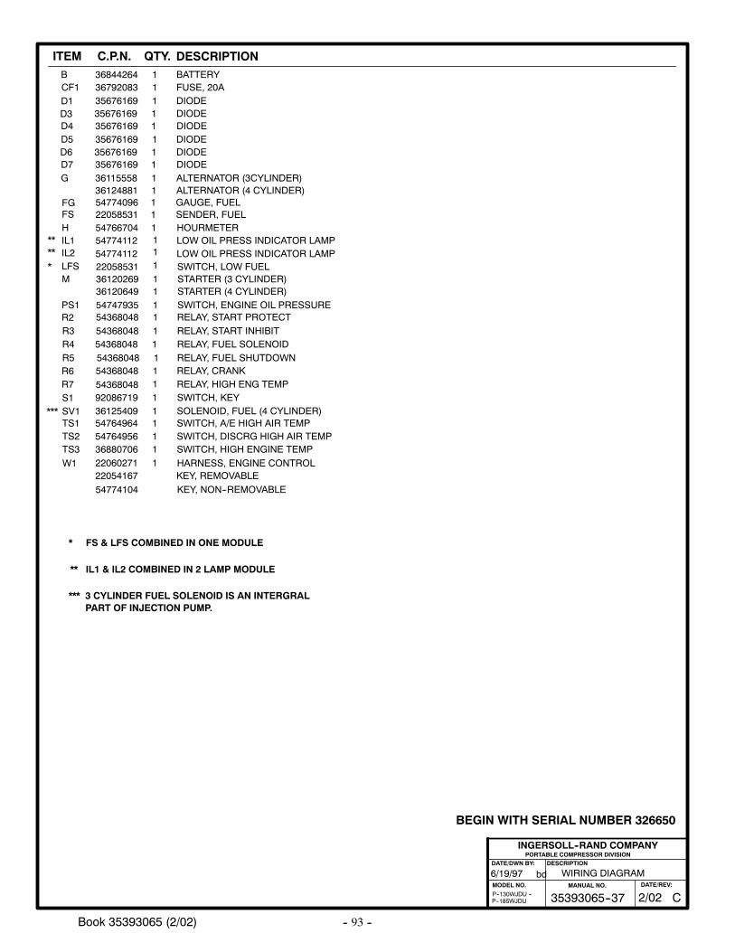
-- 93 --Book 35393065 (2/02)
PORTABLE COMPRESSOR DIVISIONDESCRIPTION
MODEL NO.
INGERSOLL--RAND COMPANY
DATE/DWN BY:
bd6/19/97
P--185WJDUP--130WJDU --
WIRING DIAGRAM
C35393065--37MANUAL NO.
2/02DATE/REV:
BEGIN WITH SERIAL NUMBER 326650
CF1 36792083 1 FUSE, 20A
36115558 1 ALTERNATOR (3CYLINDER)G
B 36844264 1 BATTERY
35676169 1 DIODED135676169 135676169 1 DIODE
D3D4
DIODE
36124881 1 ALTERNATOR (4 CYLINDER)
35676169 1 DIODED535676169 135676169 1 DIODE
D6D7
DIODE
36120269 1 STARTER (3 CYLINDER)M
54368048 1 RELAY, START PROTECTR254747935 1 SWITCH, ENGINE OIL PRESSUREPS1
54766704 1 HOURMETERH
36120649 1 STARTER (4 CYLINDER)
IL1IL2
FS
LFS
54774112 LOW OIL PRESS INDICATOR LAMP54774112 LOW OIL PRESS INDICATOR LAMP
22058531 SENDER, FUEL
22058531 SWITCH, LOW FUEL*
****
1
11
1
92086719 1 SWITCH, KEY
R6
S1
54368048 1 RELAY, CRANK
22060271 1 HARNESS, ENGINE CONTROLW1
3612540954764964
11
SOLENOID, FUEL (4 CYLINDER)SWITCH, A/E HIGH AIR TEMP
SV1TS1
5476495636880706
11
SWITCH, DISCRG HIGH AIR TEMPSWITCH, HIGH ENGINE TEMP
TS2TS3
***
54368048 1RELAY, FUEL SHUTDOWNR5
R7 54368048 RELAY, HIGH ENG TEMP1
FG 54774096 GAUGE, FUEL1
54368048 1RELAY, FUEL SOLENOIDR4
54368048 1 RELAY, START INHIBITR3
54774104 KEY, NON--REMOVABLE22054167 KEY, REMOVABLE
PART OF INJECTION PUMP.*** 3 CYLINDER FUEL SOLENOID IS AN INTERGRAL
** IL1 & IL2 COMBINED IN 2 LAMP MODULE
* FS & LFS COMBINED IN ONE MODULE
ITEM C.P.N. DESCRIPTIONQTY.
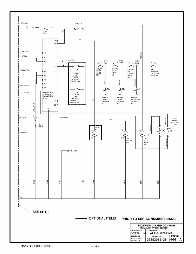
-- 94 --Book 35393065 (2/02)
6/19/97
P--185WJDUP--130WJDU --
WIRING DIAGRAM
PORTABLE COMPRESSOR DIVISIONDESCRIPTION
MODEL NO.
INGERSOLL--RAND COMPANY
DATE/DWN BY:
bd
(+)
ORN/BLK
PRS
ORN/RED
BRN
COMPRAIR
FILTERRESTRICTSWITCH S7
ENGINEAIR
FILTERRESTRICTSWITCH S6
LT BLU/ORG
LT BLU
VIO/YEL
VIO
ENGINEOILPRESSGAGEM2
AIRDISCHARGEPRESSUREGAGE M1
FUELLEVELGAGEM3
ENGINETEMPGAGEM2
COMPRTEMPGAGEM2
FUELLEVEL
MODULEU2
LT BLU/YEL
GND
G
(+)
(--)
G
(+)
(--)
ORN/YEL
ORN/BLU
ORN/W
HT
TMP
VOLTMETERM2
ENGINETEMPSENDERRT2
COMPRTEMPSENDERRT1
TACHM4
ENGTMP
ENGINEOIL PRESSSENDERRP1
LT BLU/RED
VIO
RED/BLK
RED/BLK
VIO
RED/BLK
VIO
VIO
RED/BLK
FUSE5A F2
B3
A2
A3
B5
A4
A5
A6
A7
A8
B1
B2
B8
DIAGNOSTICMODULE U1(CONNECTORP10)
A1
B4
PNK/BLK
GRY/W
HT
LT.BLU
/WHT
PNK/BLK
R1
P1
GRY/WHT GRY/WHT
BRN
BRN
BRN
BRN
BRN
BRN
BRN
DRY
BRN
P1
+12V
A C
B D
GND
ENGCPR
150 Ω
SEE SHT. 1
OPTIONAL ITEMS
A35393065--38MANUAL NO.
4/98DATE/REV:
PRIOR TO SERIAL NUMBER 326650
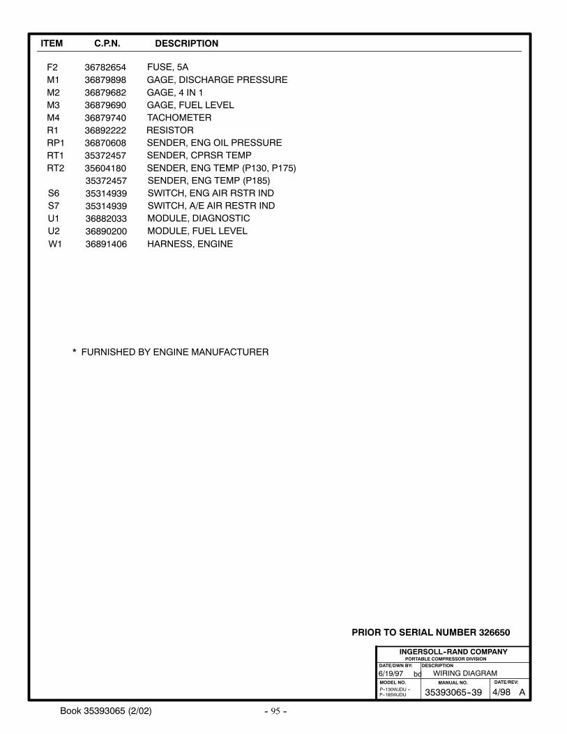
-- 95 --Book 35393065 (2/02)
ITEM C.P.N. DESCRIPTION
F2 FUSE, 5AM1M2M3M4R1RP1
RT2
S7U1U2
GAGE, DISCHARGE PRESSUREGAGE, 4 IN 1GAGE, FUEL LEVELTACHOMETERRESISTORSENDER, ENG OIL PRESSURE
SENDER, ENG TEMP (P130, P175)
SWITCH, A/E AIR RESTR INDMODULE, DIAGNOSTICMODULE, FUEL LEVEL
W1 HARNESS, ENGINE
36782654
36879740
* FURNISHED BY ENGINE MANUFACTURER
3689140636890200
3689222236870608
3688203335314939
368798983687968236879690
PORTABLE COMPRESSOR DIVISIONDESCRIPTION
MODEL NO.
INGERSOLL--RAND COMPANY
DATE/DWN BY:
bd6/19/97
P--185WJDUP--130WJDU --
WIRING DIAGRAM
RT1
S6
SENDER, CPRSR TEMP
SWITCH, ENG AIR RSTR IND35314939
3537245735604180
SENDER, ENG TEMP (P185)35372457
A35393065--39MANUAL NO.
4/98DATE/REV:
PRIOR TO SERIAL NUMBER 326650
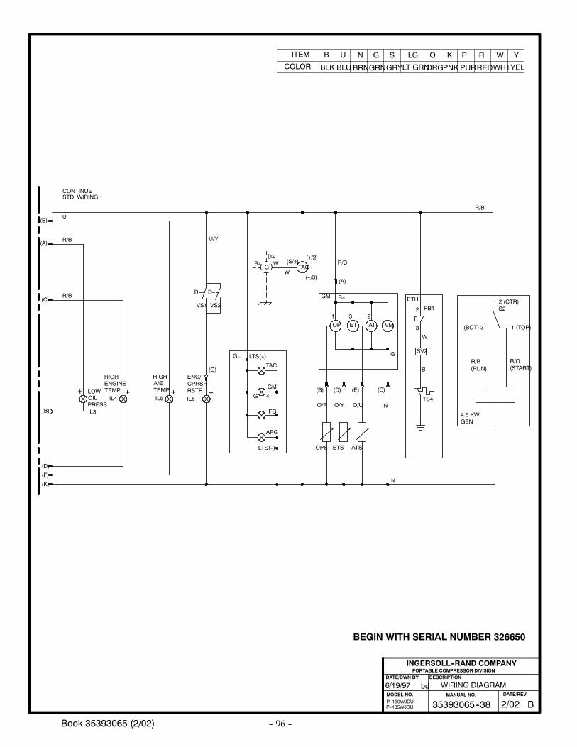
-- 96 --Book 35393065 (2/02)
6/19/97
P--185WJDUP--130WJDU --
WIRING DIAGRAM
PORTABLE COMPRESSOR DIVISIONDESCRIPTION
MODEL NO.
INGERSOLL--RAND COMPANY
DATE/DWN BY:
bd
B35393065--38MANUAL NO.
2/02DATE/REV:
BEGIN WITH SERIAL NUMBER 326650
ITEM
COLOR
B
BLK
U
BLU
N
BRN
G
GRN
S
GRY
LG
LT GRN
O
ORG
K
PNK
P
PUR
R
RED
W
WHT
Y
YEL
IL5
IL3
IL4
(B)
(A)
(E)
R/B
U
LTS(+)
OPS
OP
(B)
GM
O/R
ETS
ET
(D)
O/Y
ATS
AT
(E)
O/U
VM
R/B
(C)
N
(A)
TAC
(+/2)
(--/3)
(S/4)
APG
FG
GM
TAC
R/B
(K)
GL
TEMP
HIGHA/E
PRESS
LOWOIL
TEMP
HIGHENGINE
+ + +
W
3
2 PB1
ETH
N
LTS(--)
(F)
IL6
(G)
RSTRCPRSR
+
D D
VS1 VS2
ENG/
CONTINUESTD. WIRING
U/Y
4G
B+
G
1 3 2
GW
D+B+
SV2
B
TS4
W
(D)
R/B(C)
4.5 KWGEN
(BOT) 3
R/B(RUN)
R/O(START)
2 (CTR)S2
1 (TOP)
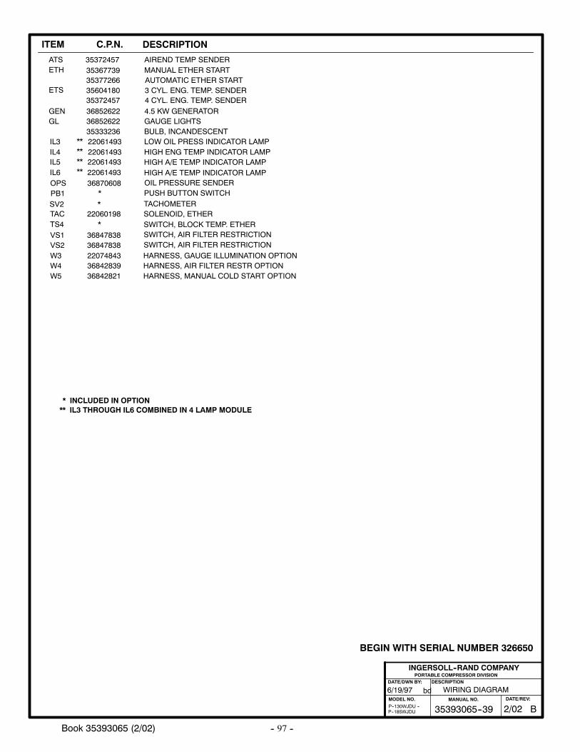
-- 97 --Book 35393065 (2/02)
PORTABLE COMPRESSOR DIVISIONDESCRIPTION
MODEL NO.
INGERSOLL--RAND COMPANY
DATE/DWN BY:
bd6/19/97
P--185WJDUP--130WJDU --
WIRING DIAGRAM
B35393065--39MANUAL NO.
2/02DATE/REV:
BEGIN WITH SERIAL NUMBER 326650
ITEM C.P.N. DESCRIPTION
36852622 GAUGE LIGHTSGL
ETS 35604180 3 CYL. ENG. TEMP. SENDER
35372457 AIREND TEMP SENDERATS
35333236 BULB, INCANDESCENT
35372457 4 CYL. ENG. TEMP. SENDER
ETH 35367739 MANUAL ETHER START35377266 AUTOMATIC ETHER START
36852622 4.5 KW GENERATORGEN
* PUSH BUTTON SWITCHPB1
22061493 HIGH A/E TEMP INDICATOR LAMP
36870608 OIL PRESSURE SENDER
IL5
OPS
22061493 HIGH ENG TEMP INDICATOR LAMPIL422061493 LOW OIL PRESS INDICATOR LAMPIL3
22061493 HIGH A/E TEMP INDICATOR LAMPIL6
********
36847838 SWITCH, AIR FILTER RESTRICTIONVS136847838 SWITCH, AIR FILTER RESTRICTIONVS222074843W3 HARNESS, GAUGE ILLUMINATION OPTION36842839W4 HARNESS, AIR FILTER RESTR OPTION36842821W5 HARNESS, MANUAL COLD START OPTION
* SWITCH, BLOCK TEMP. ETHERTS422060198
TACHOMETERTAC
*SOLENOID, ETHER
SV2
** IL3 THROUGH IL6 COMBINED IN 4 LAMP MODULE* INCLUDED IN OPTION
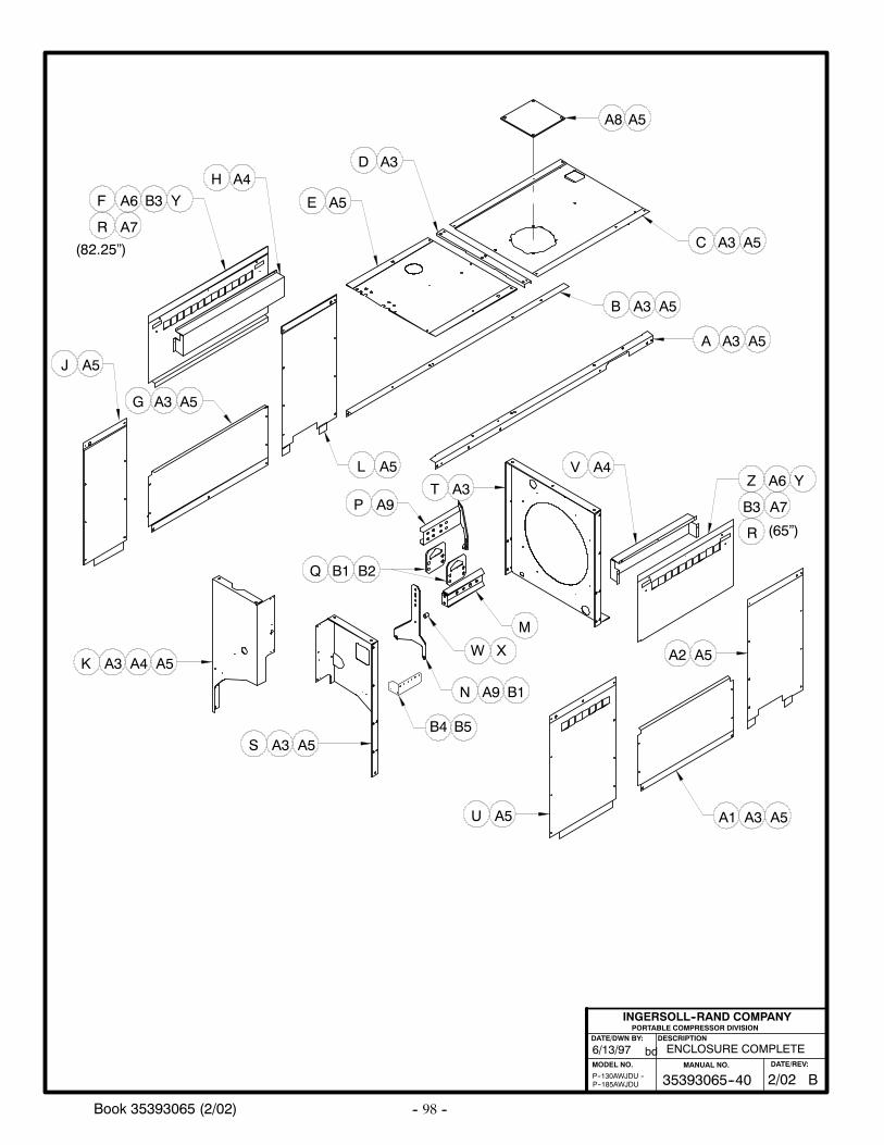
-- 98 --Book 35393065 (2/02)
ENCLOSURE COMPLETE6/13/97
PORTABLE COMPRESSOR DIVISIONDESCRIPTION
MODEL NO.
INGERSOLL--RAND COMPANY
DATE/DWN BY:
bd
P--130AWJDU --P--185AWJDU
A
B
C
A3
A5
A5
A4
A5
A5
L
M
N
P
B2
A5
A3
A5
A4Z
A1
A5
D
EA6
A3
H
J
T
G
A4
A3
U
V
A2A3
S
K
A3
A3
A5A6
A3
A5
A5
A5
A3
F
B1Q
B1A9
A9 B3
A8 A5
B3
R (65”)
(82.25”)
Y
A7R
Y
A7
A5
W X
B35393065--40MANUAL NO.
2/02DATE/REV:
B4 B5
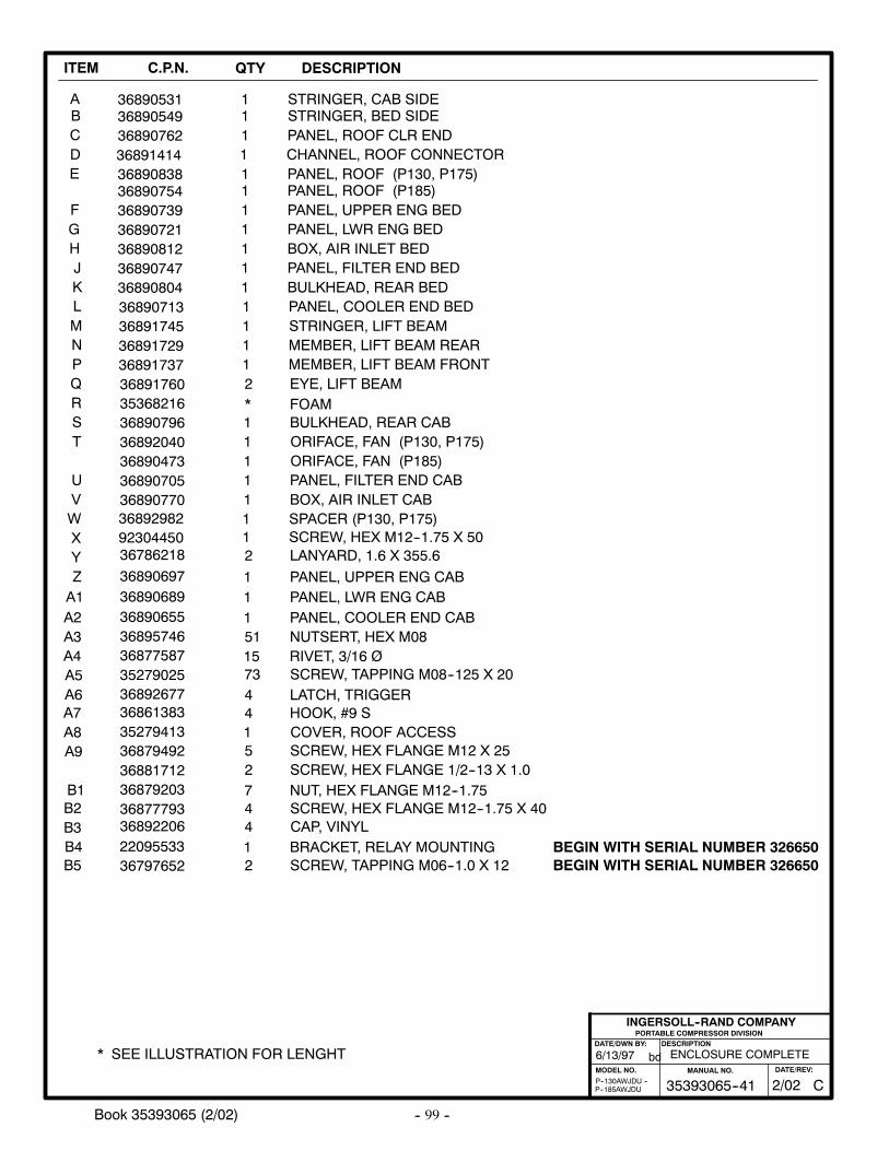
-- 99 --Book 35393065 (2/02)
ITEM C.P.N. QTY DESCRIPTION
ABCDE
368905493689076236891414
111
STRINGER, BED SIDEPANEL, ROOF CLR ENDCHANNEL, ROOF CONNECTOR
36890838 1 PANEL, ROOF (P130, P175)
36890531 1 STRINGER, CAB SIDE
FGHJKLMNPQRST
UVWXYZA1A2A3A4
36890739
3689081236890747
36890713
36891729
36891760
36890721
36892040
3689070536890770
36890697
36877587
36892677
368906893689065536895746
1
11
1
1
2
1
1
11
1
15
4
1151
PANEL, UPPER ENG BED
BOX, AIR INLET BEDPANEL, FILTER END BED
PANEL, COOLER END BED
MEMBER, LIFT BEAM REAR
EYE, LIFT BEAM
PANEL, LWR ENG BED
ORIFACE, FAN (P130, P175)
PANEL, FILTER END CABBOX, AIR INLET CAB
PANEL, UPPER ENG CAB
RIVET, 3/16 Ø
LATCH, TRIGGER
PANEL, LWR ENG CABPANEL, COOLER END CABNUTSERT, HEX M08
36890796 1 BULKHEAD, REAR CAB
36890804
36891745
36891737
1
1
1
BULKHEAD, REAR BED
STRINGER, LIFT BEAM
MEMBER, LIFT BEAM FRONT
A5A6A7
PORTABLE COMPRESSOR DIVISIONDESCRIPTION
MODEL NO.
INGERSOLL--RAND COMPANY
DATE/DWN BY:
bd
P--185AWJDUP--130AWJDU --
A8
ENCLOSURE COMPLETE6/13/97
35279025 73 SCREW, TAPPING M08--125 X 20
36890754 1 PANEL, ROOF (P185)
36890473 1 ORIFACE, FAN (P185)
36879203 7 NUT, HEX FLANGE M12--1.75
A9
B1B2 36877793 4 SCREW, HEX FLANGE M12--1.75 X 40B3
36879492 5 SCREW, HEX FLANGE M12 X 25
36892206 4 CAP, VINYL
35279413 1 COVER, ROOF ACCESS
35368216 * FOAM
* SEE ILLUSTRATION FOR LENGHT
36786218 2 LANYARD, 1.6 X 355.6
36861383 4 HOOK, #9 S
36881712 2 SCREW, HEX FLANGE 1/2--13 X 1.0
36892982 1 SPACER (P130, P175)92304450 1 SCREW, HEX M12--1.75 X 50
C35393065--41MANUAL NO.
2/02DATE/REV:
22095533 1 BRACKET, RELAY MOUNTINGB4B5 36797652 2 SCREW, TAPPING M06--1.0 X 12
BEGIN WITH SERIAL NUMBER 326650BEGIN WITH SERIAL NUMBER 326650
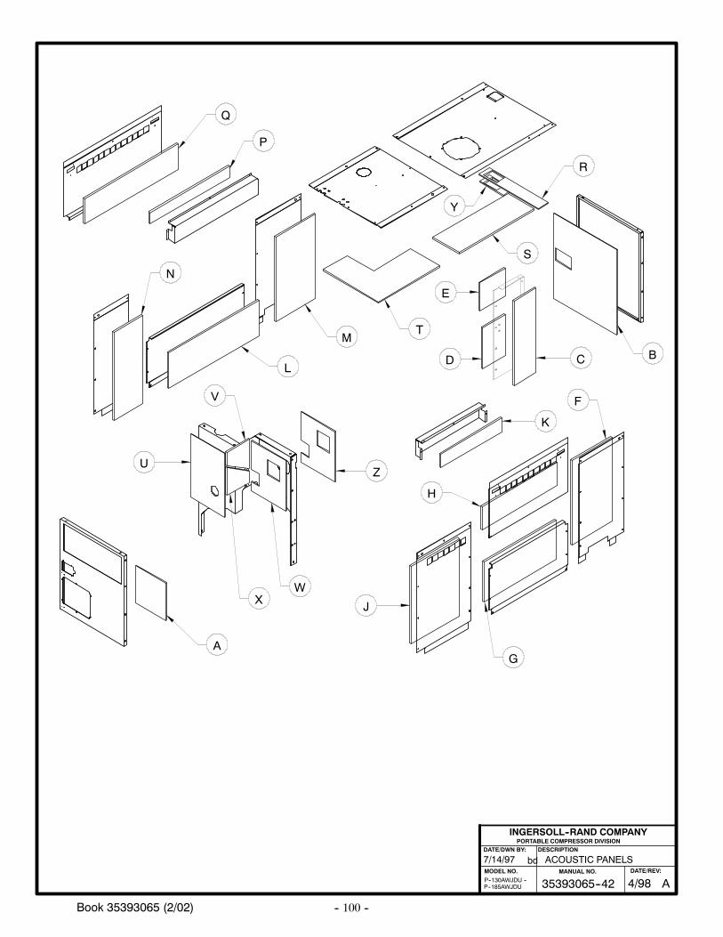
-- 100 --Book 35393065 (2/02)
ACOUSTIC PANELS7/14/97
P--185AWJDUP--130AWJDU --
PORTABLE COMPRESSOR DIVISIONDESCRIPTION
MODEL NO.
INGERSOLL--RAND COMPANY
DATE/DWN BY:
bd
A
BC
K
T
S
R
Q
P
M
N
Z
Y
D
U
J
H
E
L
V
XW
G
F
A35393065--42MANUAL NO.
4/98DATE/REV:
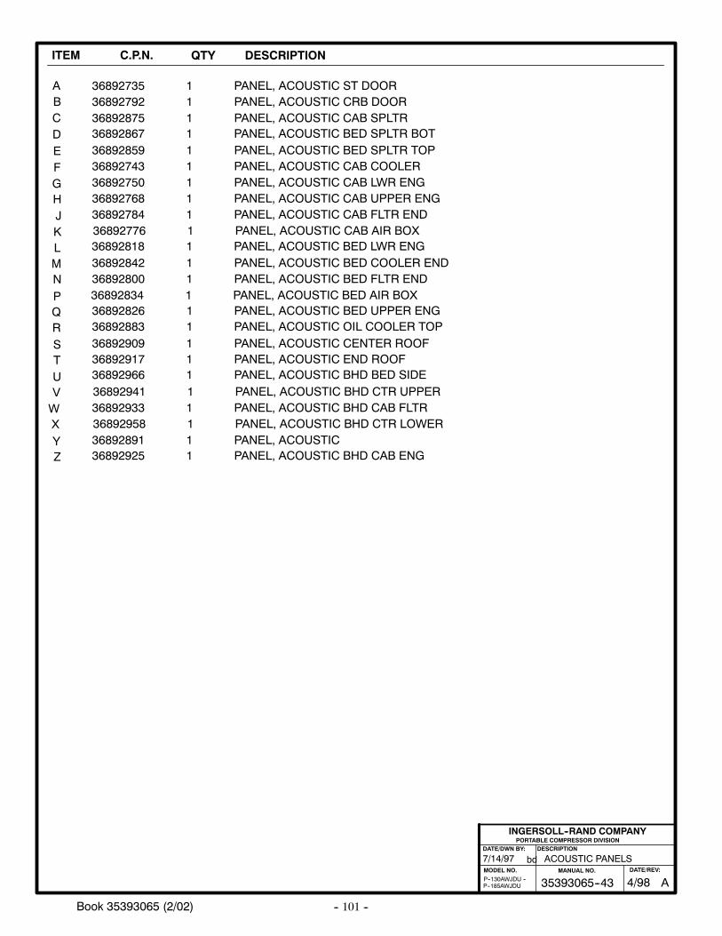
-- 101 --Book 35393065 (2/02)
ITEM C.P.N. QTY DESCRIPTION
ABCDE
3689279236892875
36892859
11
1
PANEL, ACOUSTIC CRB DOORPANEL, ACOUSTIC CAB SPLTR
PANEL, ACOUSTIC BED SPLTR TOP
36892784 1 PANEL, ACOUSTIC CAB FLTR END
36892735 1 PANEL, ACOUSTIC ST DOOR
FGHJKLMNPQRSTUVWXYZ
36892776
3689284236892800
36892909
36892941
36892818
3689289136892925
1
11
1
1
1
11
PANEL, ACOUSTIC CAB AIR BOX
PANEL, ACOUSTIC BED COOLER ENDPANEL, ACOUSTIC BED FLTR END
PANEL, ACOUSTIC CENTER ROOF
PANEL, ACOUSTIC BHD CTR UPPER
PANEL, ACOUSTIC BED LWR ENG
PANEL, ACOUSTICPANEL, ACOUSTIC BHD CAB ENG
36892958 1 PANEL, ACOUSTIC BHD CTR LOWER
3689283436892826
36892966
11
1
PANEL, ACOUSTIC BED AIR BOXPANEL, ACOUSTIC BED UPPER ENG
PANEL, ACOUSTIC BHD BED SIDE36892917 1 PANEL, ACOUSTIC END ROOF
PORTABLE COMPRESSOR DIVISIONDESCRIPTION
MODEL NO.
INGERSOLL--RAND COMPANY
DATE/DWN BY:
bd
P--185AWJDUP--130AWJDU --
36892883 1 PANEL, ACOUSTIC OIL COOLER TOP
36892743 1 PANEL, ACOUSTIC CAB COOLER
36892867 1 PANEL, ACOUSTIC BED SPLTR BOT
36892750 1 PANEL, ACOUSTIC CAB LWR ENG36892768 1 PANEL, ACOUSTIC CAB UPPER ENG
36892933 1 PANEL, ACOUSTIC BHD CAB FLTR
ACOUSTIC PANELS7/14/97
A35393065--43MANUAL NO.
4/98DATE/REV:
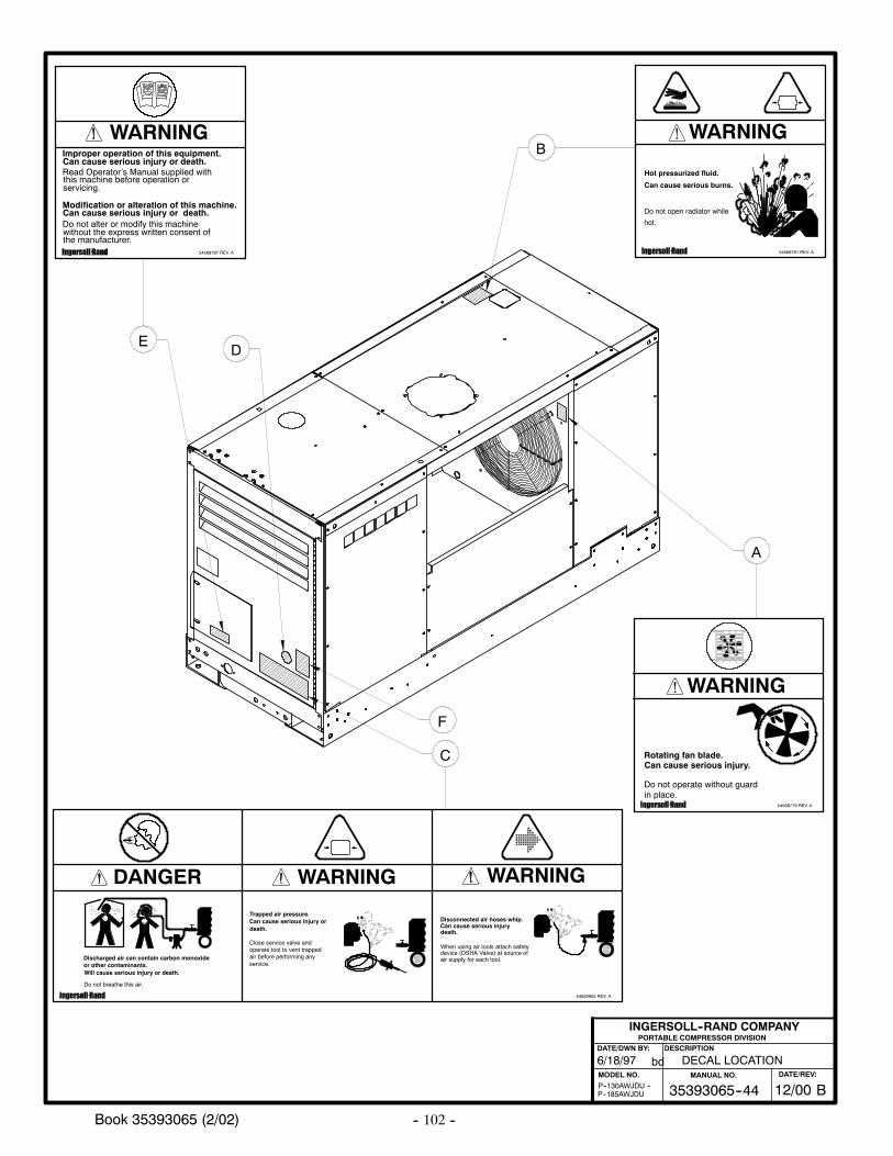
-- 102 --Book 35393065 (2/02)
PORTABLE COMPRESSOR DIVISIONDESCRIPTION
MODEL NO.
INGERSOLL--RAND COMPANY
DATE/DWN BY:
bd6/18/97
P--185AWJDUP--130AWJDU --
DECAL LOCATION
B
F
C
ED
A
B35393065--44MANUAL NO.
12/00DATE/REV:
54568779 REV. A
Rotating fan blade.Can cause serious injury.
Do not operate without guardin place.
WARNING
Discharged air can contain carbon monoxideor other contaminants.
Do not breathe this air.
Will cause serious injury or death.
Can cause serious injury ordeath.
Trapped air pressure.
Close service valve andoperate tool to vent trappedair before performing anyservice.
54629902 REV. A
device (OSHA Valve) at source ofair supply for each tool.
When using air tools attach safety
Disconnected air hoses whip.Can cause serious injurydeath.
DANGER WARNING WARNING
54568787 REV. A
Improper operation of this equipment.Can cause serious injury or death.
this machine before operation orservicing.
Read Operator’s Manual supplied with
Modification or alteration of this machine.Can cause serious injury or death.Do not alter or modify this machinewithout the express written consent ofthe manufacturer.
WARNING
54568761 REV. A
Hot pressurized fluid.
Can cause serious burns.
Do not open radiator while
hot.
WARNING
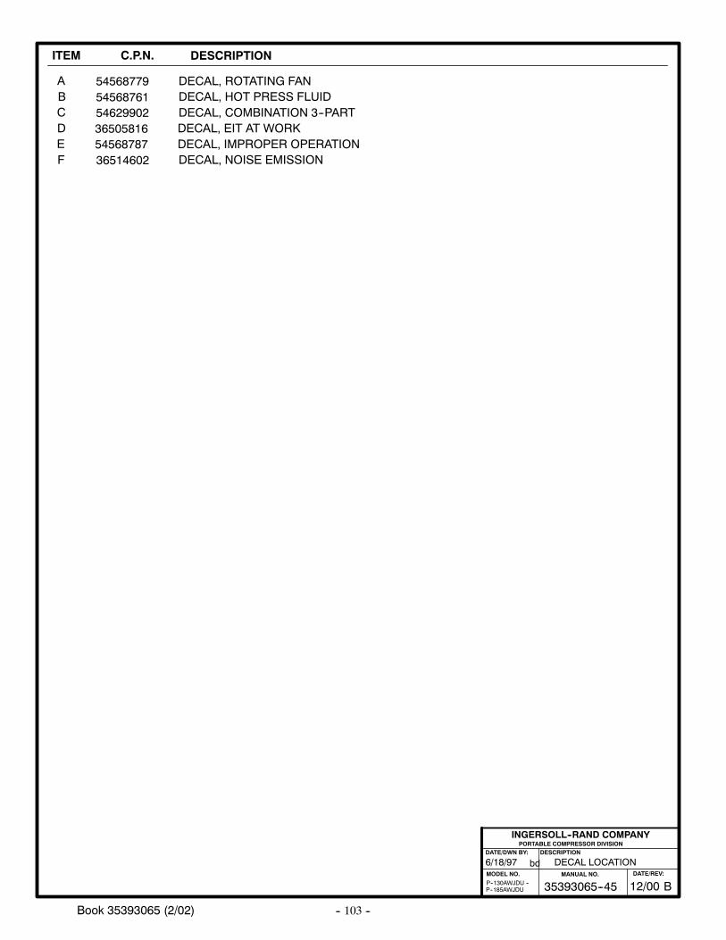
-- 103 --Book 35393065 (2/02)
ITEM C.P.N. DESCRIPTION
ABCDE
54568761
54568787
DECAL, ROTATING FANDECAL, HOT PRESS FLUID
DECAL, IMPROPER OPERATION36514602 DECAL, NOISE EMISSION
54568779
F
5462990236505816
DECAL, COMBINATION 3--PARTDECAL, EIT AT WORK
PORTABLE COMPRESSOR DIVISIONDESCRIPTION
MODEL NO.
INGERSOLL--RAND COMPANY
DATE/DWN BY:
bd
P--185AWJDUP--130AWJDU --
6/18/97 DECAL LOCATION
B35393065--45MANUAL NO.
12/00DATE/REV:
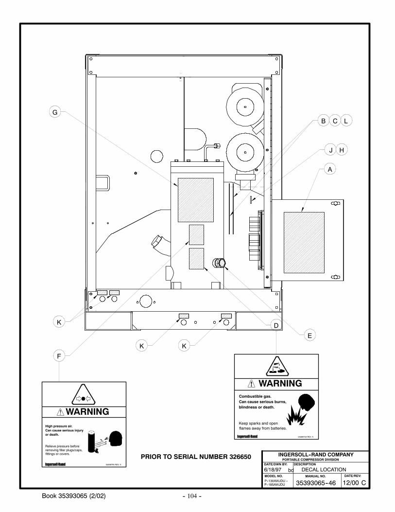
-- 104 --Book 35393065 (2/02)
PORTABLE COMPRESSOR DIVISIONDESCRIPTION
MODEL NO.
INGERSOLL--RAND COMPANY
DATE/DWN BY:
bd6/18/97
P--185AWJDUP--130AWJDU --
DECAL LOCATION
A
B
D
E
F
GC
K
K
L
J H
C35393065--46MANUAL NO.
12/00DATE/REV:
K
54568753 REV. A
Combustible gas.Can cause serious burns,blindness or death.
Keep sparks and openflames away from batteries.
WARNING
+
54568795 REV. A
High pressure air.Can cause serious injury
Relieve pressure beforeremoving filler plugs/caps,fittings or covers.
or death.
WARNING
PRIOR TO SERIAL NUMBER 326650
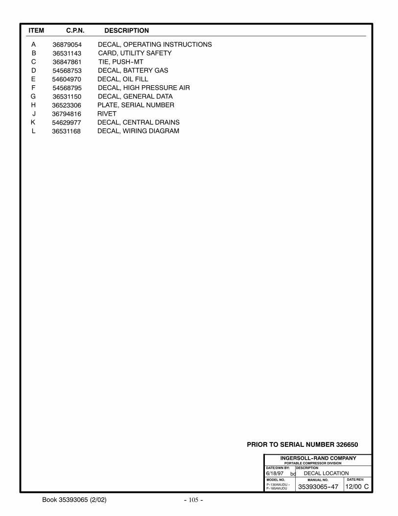
-- 105 --Book 35393065 (2/02)
ITEM C.P.N. DESCRIPTION
ABCDE
36531143368478615456875354604970
CARD, UTILITY SAFETYDECAL, OPERATING INSTRUCTIONS
DECAL, BATTERY GASDECAL, OIL FILL
54568795 DECAL, HIGH PRESSURE AIR
36879054
TIE, PUSH--MT
FGH
3653115036523306
DECAL, GENERAL DATAPLATE, SERIAL NUMBER
PORTABLE COMPRESSOR DIVISIONDESCRIPTION
MODEL NO.
INGERSOLL--RAND COMPANY
DATE/DWN BY:
bd
P--185AWJDUP--130AWJDU --
6/18/97 DECAL LOCATION
J 36794816 RIVETK 54629977 DECAL, CENTRAL DRAINSL 36531168 DECAL, WIRING DIAGRAM
C35393065--47MANUAL NO.
12/00DATE/REV:
PRIOR TO SERIAL NUMBER 326650

-- 106 --Book 35393065 (2/02)
PORTABLE COMPRESSOR DIVISIONDESCRIPTION
MODEL NO.
INGERSOLL--RAND COMPANY
DATE/DWN BY:
bd6/18/97
P--185AWJDUP--130AWJDU --
DECAL LOCATION
A
B
D
E
F
C
G
G
J H
D35393065--46MANUAL NO.
2/02DATE/REV:
G
54568753 REV. A
Combustible gas.Can cause serious burns,blindness or death.
Keep sparks and openflames away from batteries.
WARNING
+
54568795 REV. A
High pressure air.Can cause serious injury
Relieve pressure beforeremoving filler plugs/caps,fittings or covers.
or death.
WARNING
BEGIN WITH SERIAL NUMBER 326650
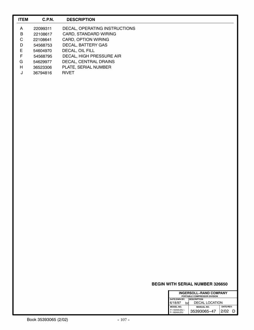
-- 107 --Book 35393065 (2/02)
ITEM C.P.N. DESCRIPTION
ABCDE
22108617
5456875354604970
CARD, STANDARD WIRINGDECAL, OPERATING INSTRUCTIONS
DECAL, BATTERY GASDECAL, OIL FILL
54568795 DECAL, HIGH PRESSURE AIR
22099311
FGH 36523306 PLATE, SERIAL NUMBER
PORTABLE COMPRESSOR DIVISIONDESCRIPTION
MODEL NO.
INGERSOLL--RAND COMPANY
DATE/DWN BY:
bd
P--185AWJDUP--130AWJDU --
6/18/97 DECAL LOCATION
J 36794816 RIVET
54629977 DECAL, CENTRAL DRAINS
22108641 CARD, OPTION WIRING
D35393065--47MANUAL NO.
2/02DATE/REV:
BEGIN WITH SERIAL NUMBER 326650
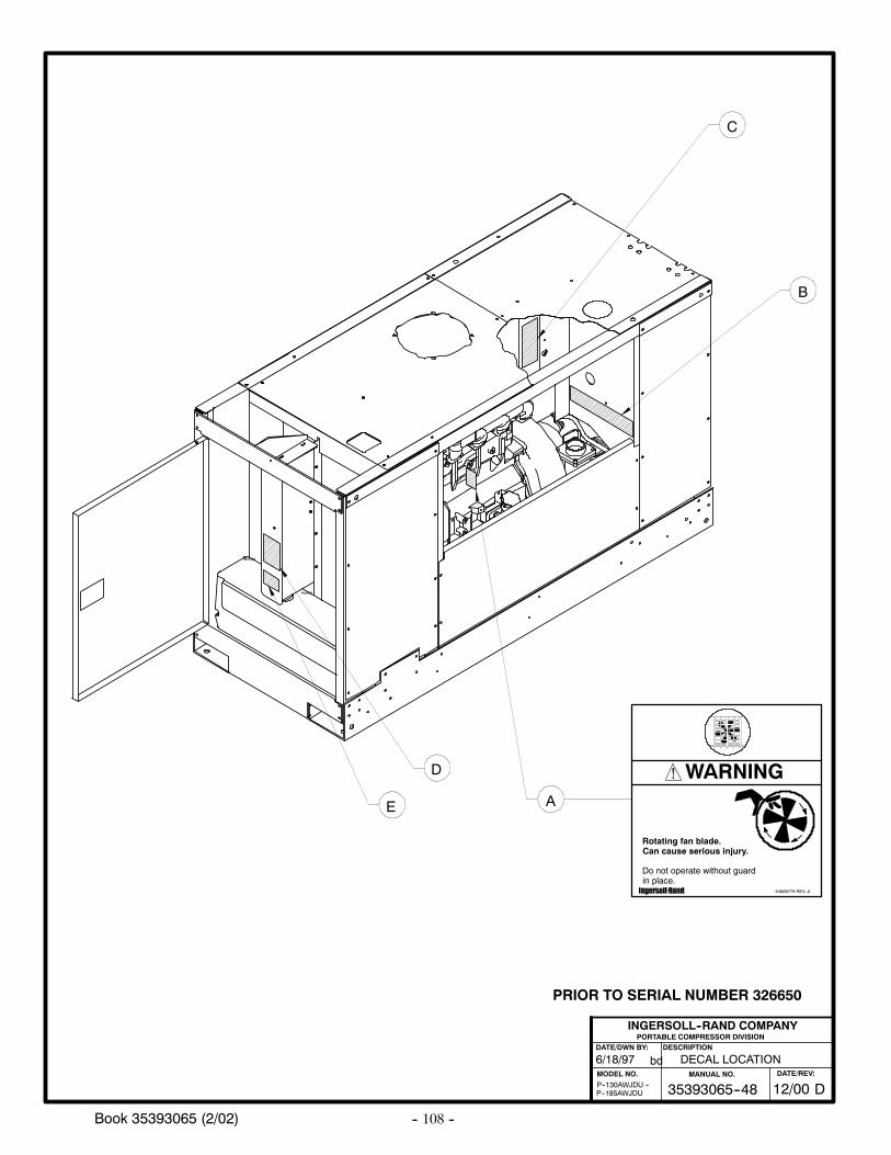
-- 108 --Book 35393065 (2/02)
PORTABLE COMPRESSOR DIVISIONDESCRIPTION
MODEL NO.
INGERSOLL--RAND COMPANY
DATE/DWN BY:
bd6/18/97
P--185AWJDUP--130AWJDU --
DECAL LOCATION
A
B
C
RETURN
PICKUP
D
E
D35393065--48MANUAL NO.
12/00DATE/REV:
54568779 REV. A
Rotating fan blade.Can cause serious injury.
Do not operate without guardin place.
WARNING
PRIOR TO SERIAL NUMBER 326650
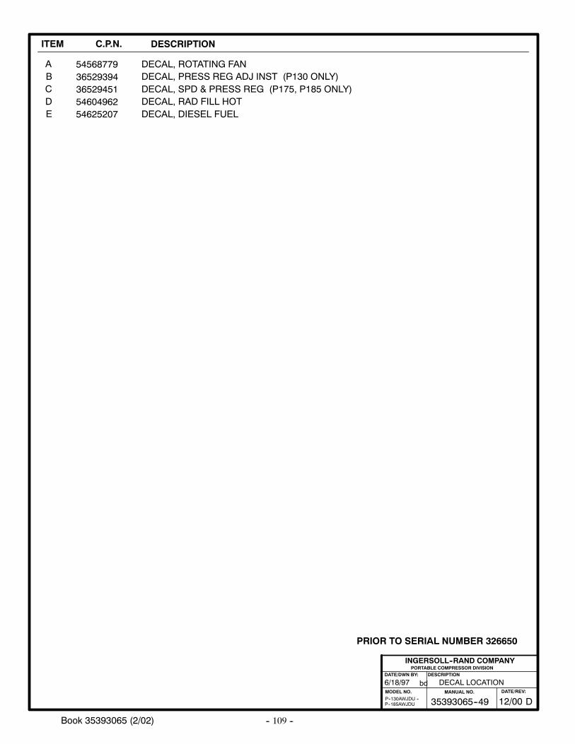
-- 109 --Book 35393065 (2/02)
ITEM C.P.N. DESCRIPTION
ABC
3652939436529451
DECAL, PRESS REG ADJ INST (P130 ONLY)DECAL, ROTATING FAN54568779
DECAL, SPD & PRESS REG (P175, P185 ONLY)
PORTABLE COMPRESSOR DIVISIONDESCRIPTION
MODEL NO.
INGERSOLL--RAND COMPANY
DATE/DWN BY:
bd
P--185AWJDUP--130AWJDU --
6/18/97 DECAL LOCATION
DE
5460496254625207
DECAL, RAD FILL HOTDECAL, DIESEL FUEL
D35393065--49MANUAL NO.
12/00DATE/REV:
PRIOR TO SERIAL NUMBER 326650
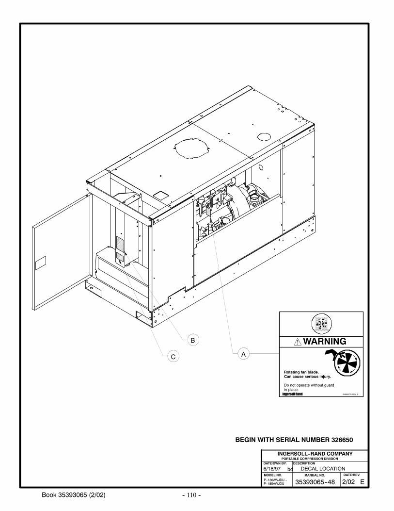
-- 110 --Book 35393065 (2/02)
PORTABLE COMPRESSOR DIVISIONDESCRIPTION
MODEL NO.
INGERSOLL--RAND COMPANY
DATE/DWN BY:
bd6/18/97
P--185AWJDUP--130AWJDU --
DECAL LOCATION
A
RETURN
PICKUP
B
C
E35393065--48MANUAL NO.
2/02DATE/REV:
54568779 REV. A
Rotating fan blade.Can cause serious injury.
Do not operate without guardin place.
WARNING
BEGIN WITH SERIAL NUMBER 326650
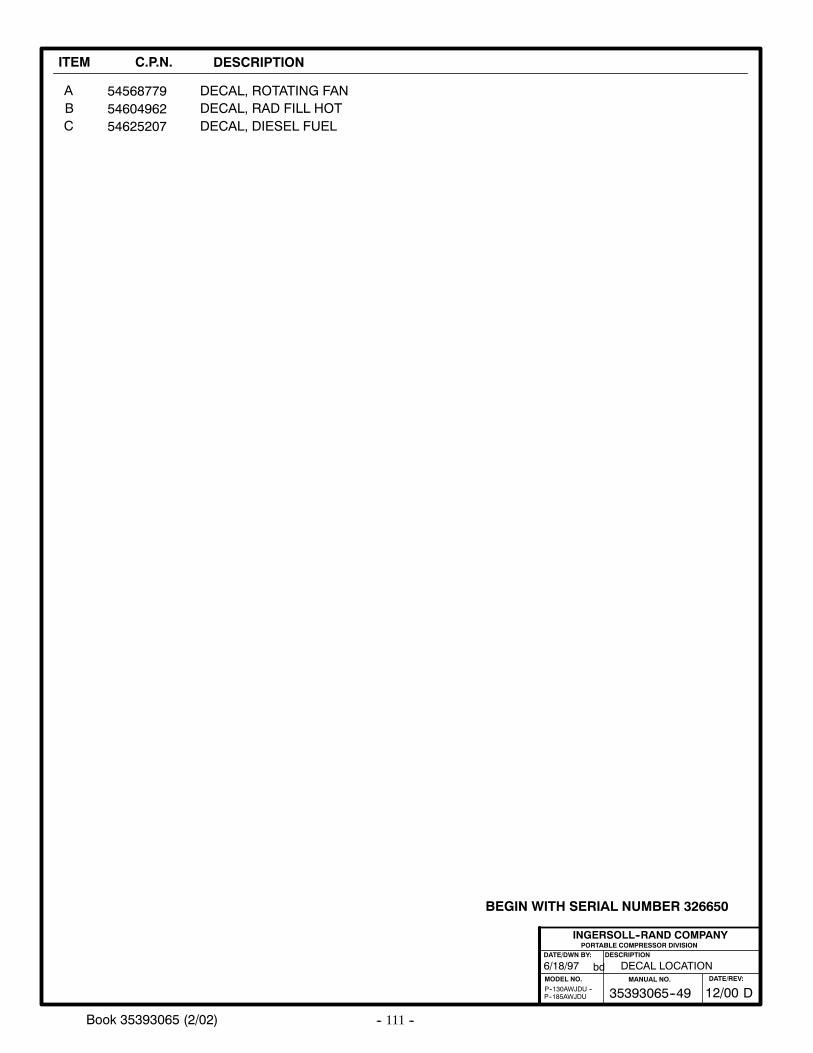
-- 111 --Book 35393065 (2/02)
ITEM C.P.N. DESCRIPTION
ABC
DECAL, ROTATING FAN54568779
PORTABLE COMPRESSOR DIVISIONDESCRIPTION
MODEL NO.
INGERSOLL--RAND COMPANY
DATE/DWN BY:
bd
P--185AWJDUP--130AWJDU --
6/18/97 DECAL LOCATION
5460496254625207
DECAL, RAD FILL HOTDECAL, DIESEL FUEL
D35393065--49MANUAL NO.
12/00DATE/REV:
BEGIN WITH SERIAL NUMBER 326650
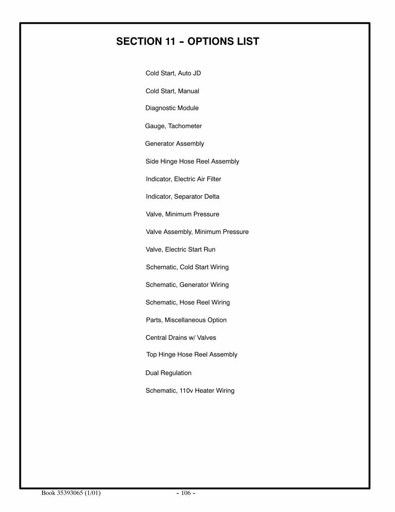
-- 106 --Book 35393065 (1/01)
SECTION 11 -- OPTIONS LIST
Cold Start, Auto JD
Diagnostic Module
Cold Start, Manual
Indicator, Electric Air Filter
Side Hinge Hose Reel Assembly
Gauge, Tachometer
Schematic, Cold Start Wiring
Parts, Miscellaneous Option
Valve, Electric Start Run
Valve, Minimum Pressure
Valve Assembly, Minimum Pressure
Indicator, Separator Delta
Schematic, Generator Wiring
Schematic, Hose Reel Wiring
Generator Assembly
Central Drains w/ Valves
Top Hinge Hose Reel Assembly
Dual Regulation
Schematic, 110v Heater Wiring
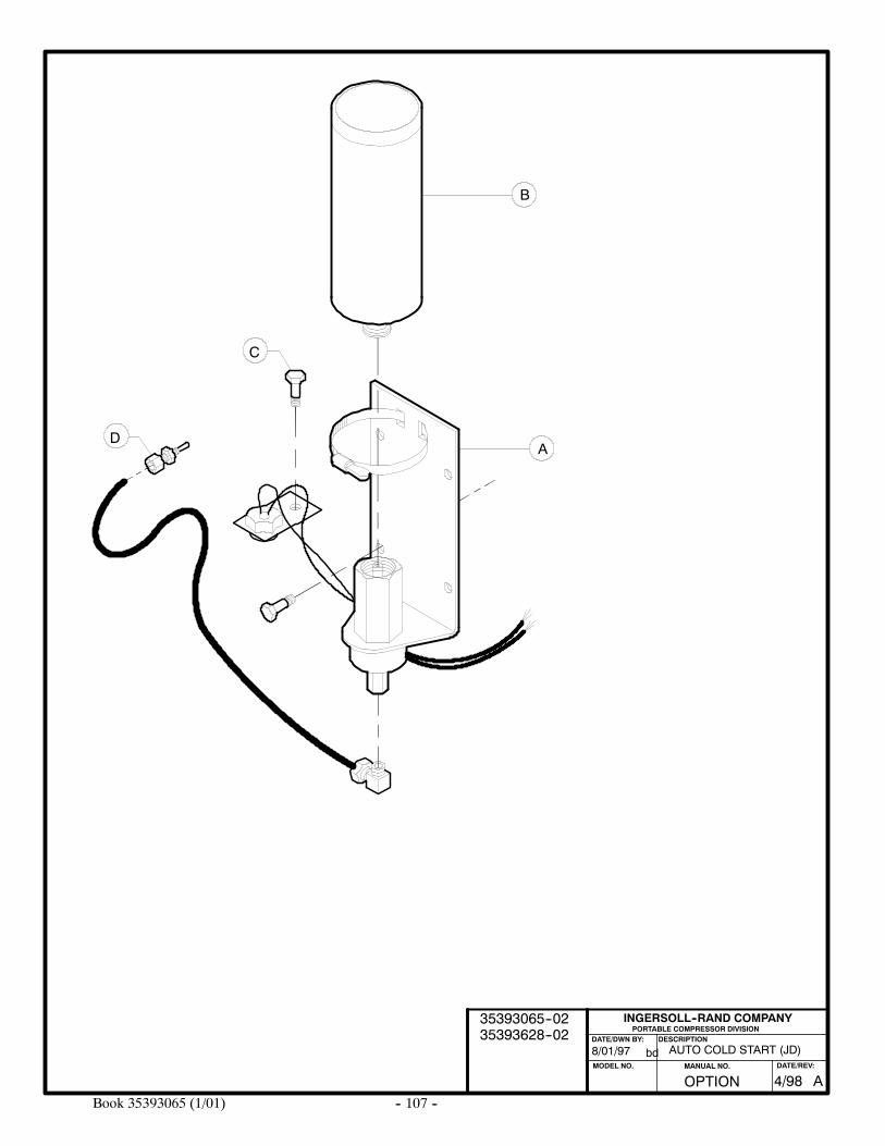
-- 107 --Book 35393065 (1/01)
PORTABLE COMPRESSOR DIVISIONDESCRIPTION
MODEL NO.
INGERSOLL--RAND COMPANY
DATE/DWN BY:
bd
C
AD
B
8/01/97 AUTO COLD START (JD)
OPTION AMANUAL NO. DATE/REV:
4/98
35393065--0235393628--02
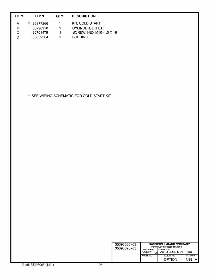
-- 108 --Book 35393065 (1/01)
ITEM C.P.N. QTY DESCRIPTION
PORTABLE COMPRESSOR DIVISIONDESCRIPTION
MODEL NO.
INGERSOLL--RAND COMPANY
DATE/DWN BY:
bd
ABCD
35377266 KIT, COLD START136796910 CYLINDER, ETHER196701479 SCREW, HEX M10--1.5 X 16136889384 BUSHING1
AUTO COLD START (JD)
*
* SEE WIRING SCHEMATIC FOR COLD START KIT
8/01/97
OPTION AMANUAL NO. DATE/REV:
4/98
35393065--0335393628--03
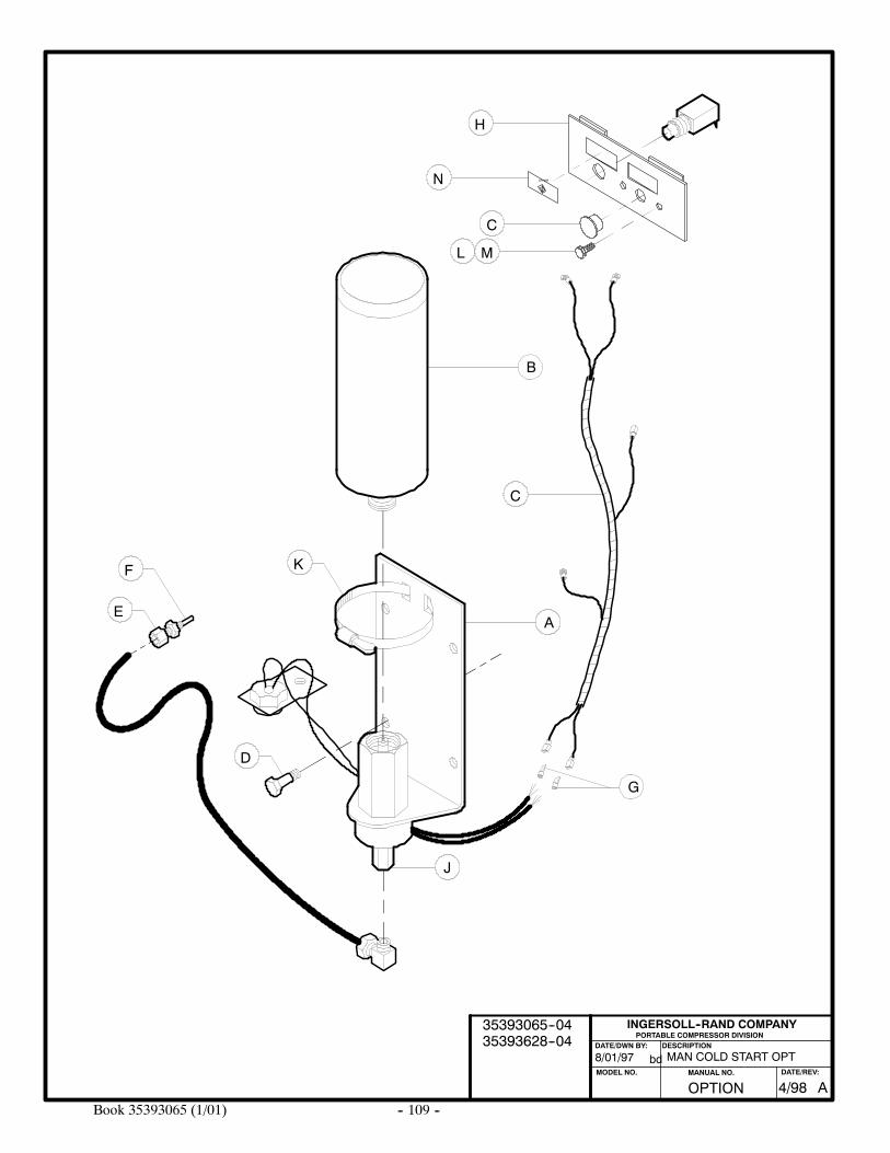
-- 109 --Book 35393065 (1/01)
PORTABLE COMPRESSOR DIVISIONDESCRIPTION
MODEL NO.
INGERSOLL--RAND COMPANY
DATE/DWN BY:
bd
D
C
A
F
E
B
G
K
J
MAN COLD START OPT
ETHERN
H
C
M
8/01/97
L
OPTION AMANUAL NO. DATE/REV:
4/98
35393065--0435393628--04
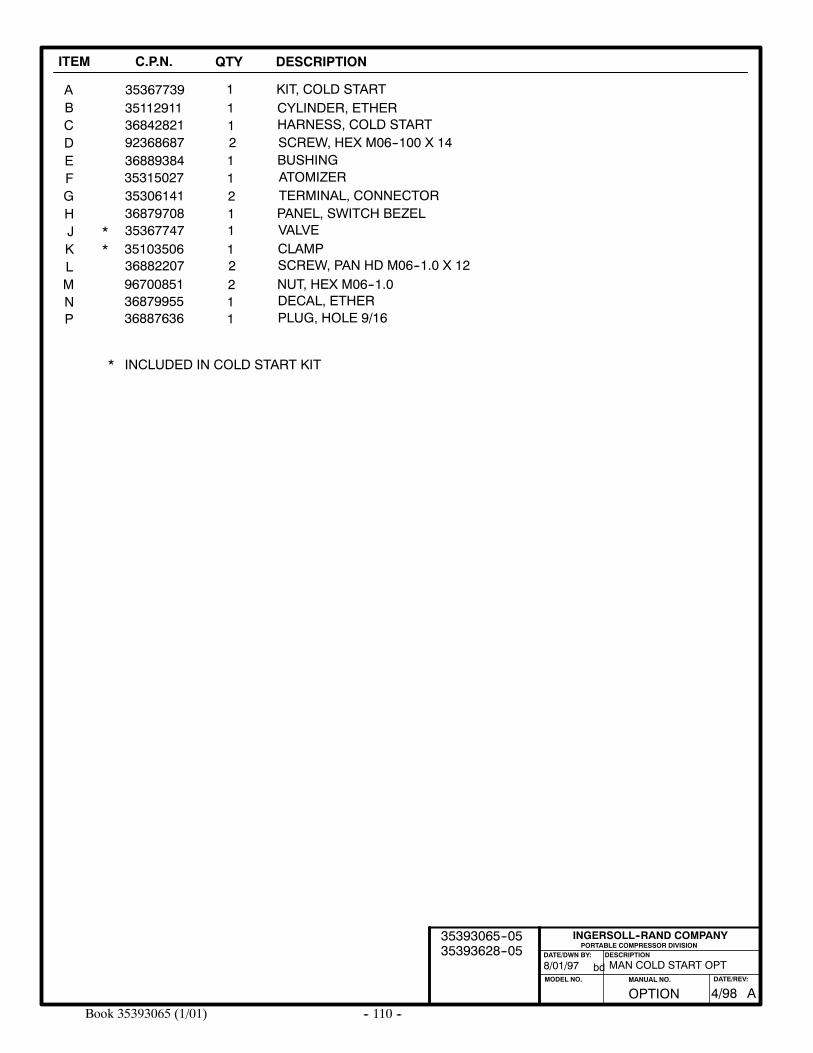
-- 110 --Book 35393065 (1/01)
ITEM C.P.N. QTY DESCRIPTION
PORTABLE COMPRESSOR DIVISIONDESCRIPTION
MODEL NO.
INGERSOLL--RAND COMPANY
DATE/DWN BY:
bd
ABCDEFGHJK
35367739 KIT, COLD START135112911 CYLINDER, ETHER136842821 HARNESS, COLD START192368687 SCREW, HEX M06--100 X 14236889384 BUSHING135315027 ATOMIZER135306141 TERMINAL, CONNECTOR236879708 PANEL, SWITCH BEZEL135367747 VALVE135103506 CLAMP1
MAN COLD START OPT
LM
36882207 SCREW, PAN HD M06--1.0 X 12296700851 NUT, HEX M06--1.02
**
* INCLUDED IN COLD START KIT
8/01/97
N 36879955 DECAL, ETHER1P 36887636 PLUG, HOLE 9/161
OPTION AMANUAL NO. DATE/REV:
4/98
35393065--0535393628--05
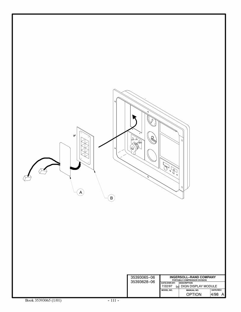
-- 111 --Book 35393065 (1/01)
OFF ON
START
00000
DIGN DISPLAY MODULE7/22/97
PORTABLE COMPRESSOR DIVISIONDESCRIPTION
MODEL NO.
INGERSOLL--RAND COMPANY
DATE/DWN BY:
bd
BA
OPTION AMANUAL NO. DATE/REV:
4/98
35393065--0635393628--06
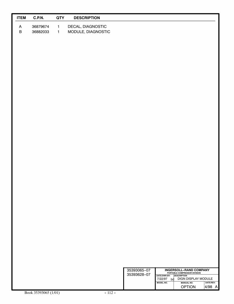
-- 112 --Book 35393065 (1/01)
ITEM C.P.N. QTY DESCRIPTION
AB 36882033
3687967411
MODULE, DIAGNOSTICDECAL, DIAGNOSTIC
DIGN DISPLAY MODULE
PORTABLE COMPRESSOR DIVISIONDESCRIPTION
MODEL NO.
INGERSOLL--RAND COMPANY
DATE/DWN BY:
bd7/22/97
OPTION AMANUAL NO. DATE/REV:
4/98
35393065--0735393628--07
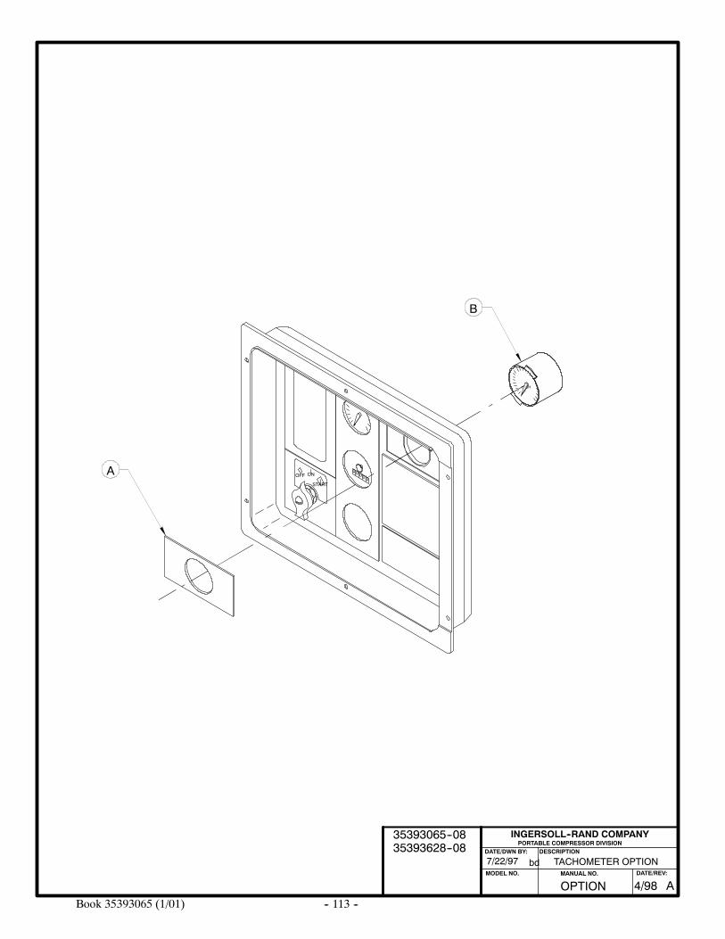
-- 113 --Book 35393065 (1/01)
OFF ON
START
00000
TACHOMETER OPTION
CHT
B
A
PORTABLE COMPRESSOR DIVISIONDESCRIPTION
MODEL NO.
INGERSOLL--RAND COMPANY
DATE/DWN BY:
bd7/22/97
OPTION AMANUAL NO. DATE/REV:
4/98
35393065--0835393628--08
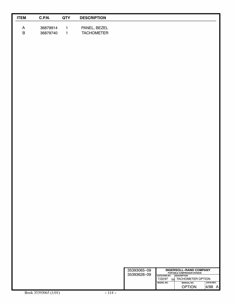
-- 114 --Book 35393065 (1/01)
ITEM C.P.N. QTY DESCRIPTION
AB
368799141
PANEL, BEZEL136879740 TACHOMETER
TACHOMETER OPTION
PORTABLE COMPRESSOR DIVISIONDESCRIPTION
MODEL NO.
INGERSOLL--RAND COMPANY
DATE/DWN BY:
bd7/22/97
OPTION AMANUAL NO. DATE/REV:
4/98
35393065--0935393628--09
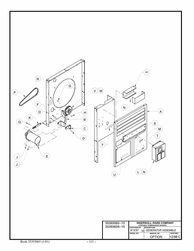
-- 115 --Book 35393065 (1/01)
GENERATOR ASSEMBLE8/12/97
PORTABLE COMPRESSOR DIVISIONDESCRIPTION
MODEL NO.
INGERSOLL--RAND COMPANY
DATE/DWN BY:
bd
VOLTMETER
A
B
C
E
D
Q
D
K
P
F
J
R
T
NL
T
H
V
**
W
N
S
M
U
J
G
OPTION CMANUAL NO. DATE/REV:
12/98
35393065--1035393628--10
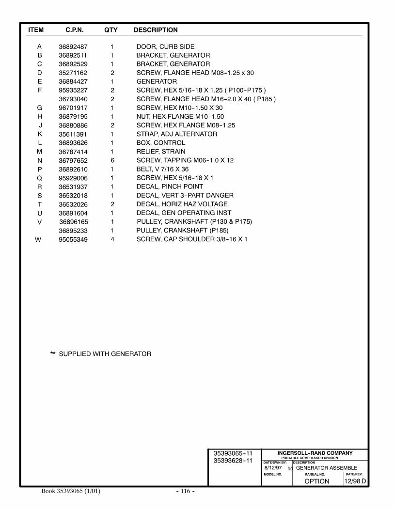
-- 116 --Book 35393065 (1/01)
ITEM C.P.N. QTY DESCRIPTION
AB
368924871
DOOR, CURB SIDE136892511 BRACKET, GENERATOR
PORTABLE COMPRESSOR DIVISIONDESCRIPTION
MODEL NO.
INGERSOLL--RAND COMPANY
DATE/DWN BY:
bd
CDEF
GHJKLMNPQRSTUV
W
36892529352711623688442795935227
9670191736879195
36893626
3688088635611391
3678741436797652368926109592900636531937
1212
1121116111
BRACKET, GENERATORSCREW, FLANGE HEAD M08--1.25 x 30GENERATORSCREW, HEX 5/16--18 X 1.25 ( P100--P175 )
SCREW, HEX M10--1.50 X 30NUT, HEX FLANGE M10--1.50SCREW, HEX FLANGE M08--1.25STRAP, ADJ ALTERNATORBOX, CONTROLRELIEF, STRAINSCREW, TAPPING M06--1.0 X 12BELT, V 7/16 X 36SCREW, HEX 5/16--18 X 1DECAL, PINCH POINT
36532018
36896165
3653202636891604
1
121
PULLEY, CRANKSHAFT (P130 & P175)
DECAL, VERT 3--PART DANGERDECAL, HORIZ HAZ VOLTAGEDECAL, GEN OPERATING INST
95055349 4 SCREW, CAP SHOULDER 3/8--16 X 136895233 1 PULLEY, CRANKSHAFT (P185)
** SUPPLIED WITH GENERATOR
GENERATOR ASSEMBLE8/12/97
36793040 2 SCREW, FLANGE HEAD M16--2.0 X 40 ( P185 )
OPTION DMANUAL NO. DATE/REV:
12/98
35393065--1135393628--11
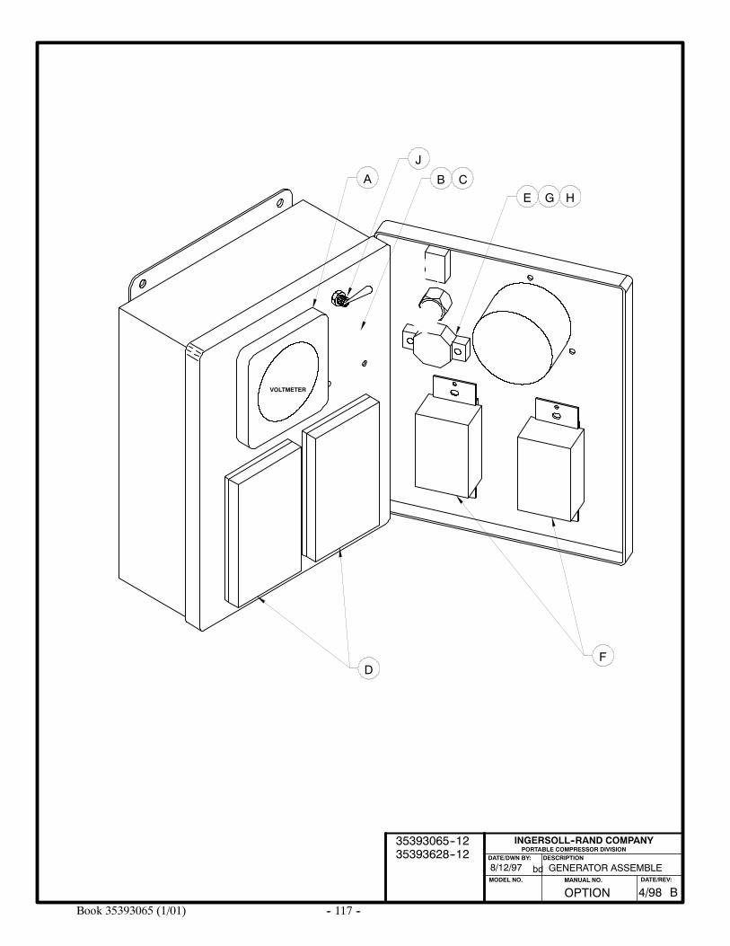
-- 117 --Book 35393065 (1/01)
GENERATOR ASSEMBLE8/12/97
PORTABLE COMPRESSOR DIVISIONDESCRIPTION
MODEL NO.
INGERSOLL--RAND COMPANY
DATE/DWN BY:
bd
VOLTMETER
A B
D
C
E
F
J
G H
OPTION BMANUAL NO. DATE/REV:
4/98
35393065--1235393628--12
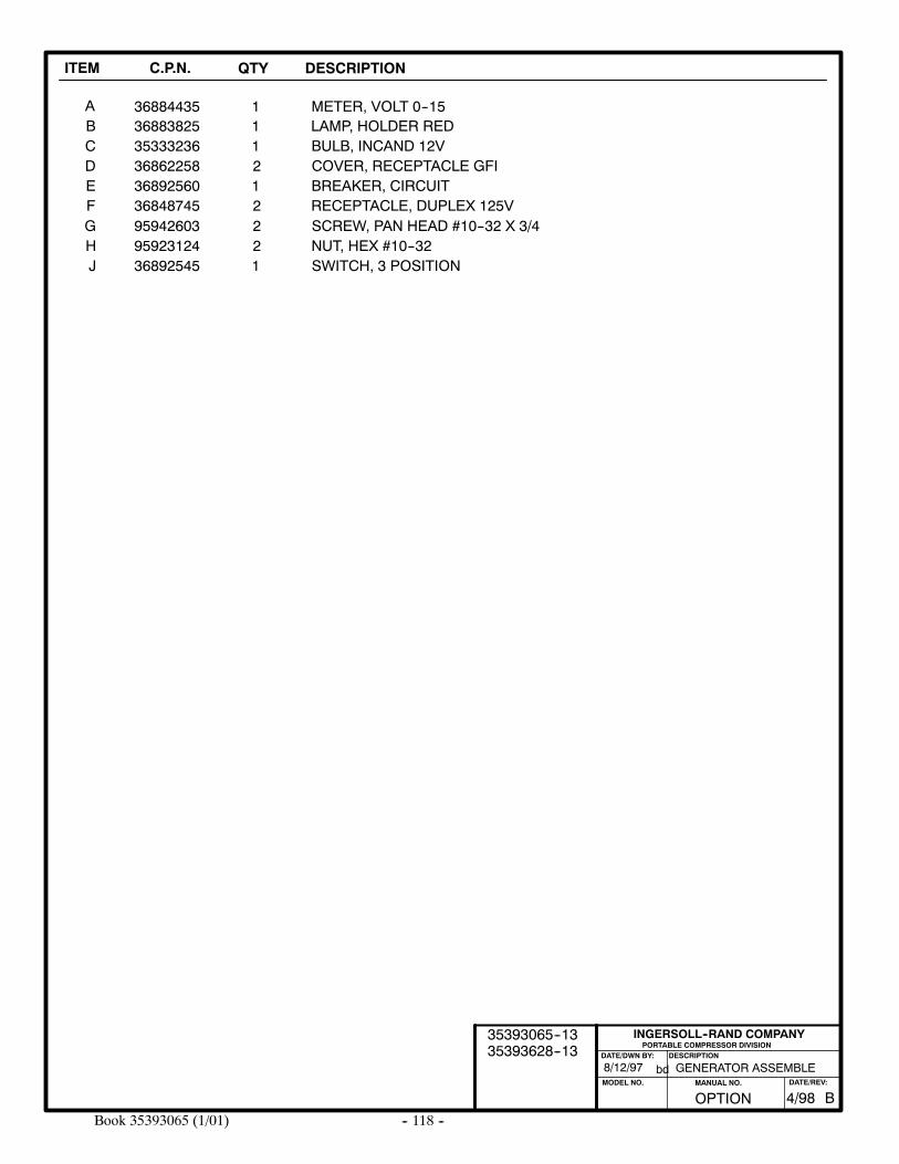
-- 118 --Book 35393065 (1/01)
ITEM C.P.N. QTY DESCRIPTION
AB
368844351
METER, VOLT 0--15136883825 LAMP, HOLDER RED
PORTABLE COMPRESSOR DIVISIONDESCRIPTION
MODEL NO.
INGERSOLL--RAND COMPANY
DATE/DWN BY:
bd
CDEF
35333236368622583689256036848745
1212
BULB, INCAND 12VCOVER, RECEPTACLE GFIBREAKER, CIRCUITRECEPTACLE, DUPLEX 125V
GENERATOR ASSEMBLE8/12/97
GHJ
959426039592312436892545
221
SCREW, PAN HEAD #10--32 X 3/4NUT, HEX #10--32SWITCH, 3 POSITION
OPTION BMANUAL NO. DATE/REV:
4/98
35393065--1335393628--13
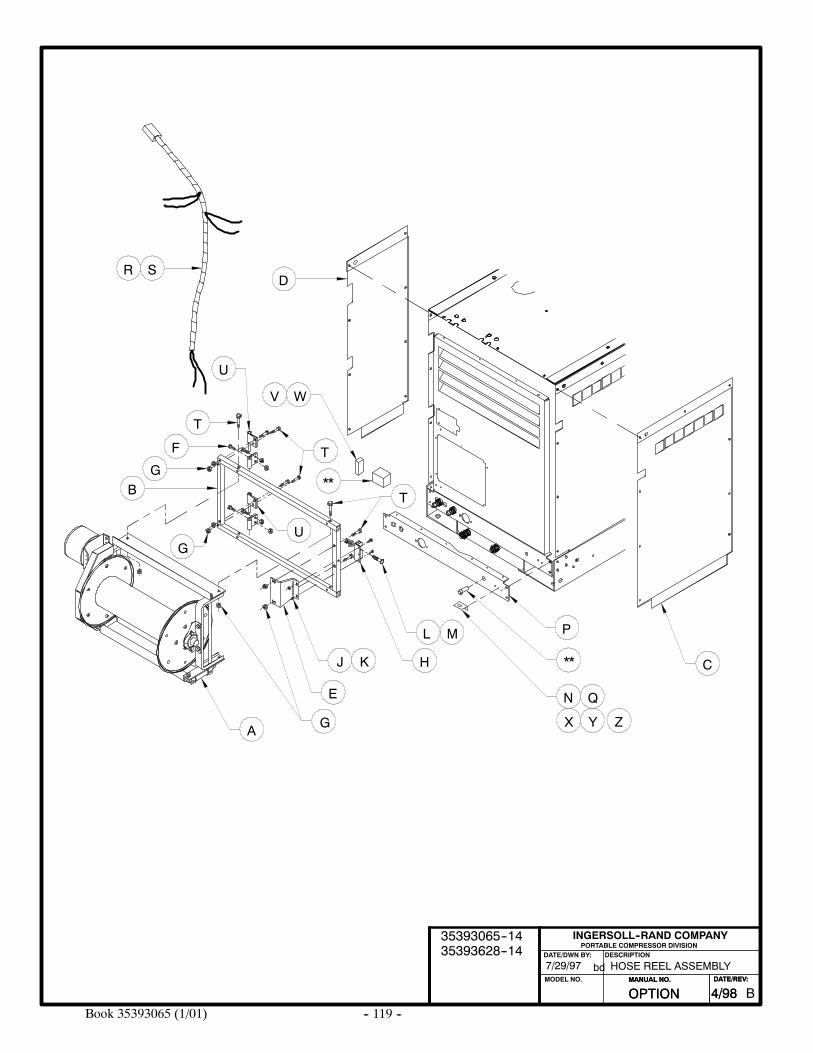
-- 119 --Book 35393065 (1/01)
HOSE REEL ASSEMBLY7/29/97
PORTABLE COMPRESSOR DIVISIONDESCRIPTION
MODEL NO.
INGERSOLL--RAND COMPANY
DATE/DWN BY:
bd
A
C
E
G
H
L P
**
N
T
T
J
B
D
T
U
W
**
F
U
M
Q
K
G
G
S
V
X Y Z
R
OPTION BMANUAL NO. DATE/REV:
4/98
35393065--1435393628--14
OPTIONMANUAL NO. DATE/REV:
4/98
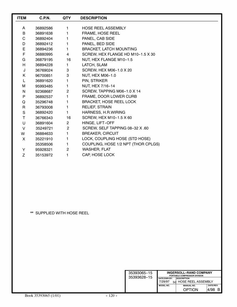
-- 120 --Book 35393065 (1/01)
ITEM C.P.N. QTY DESCRIPTION
AB
368925861
HOSE REEL ASSEMBLY136891638 FRAME, HOSE REEL
PORTABLE COMPRESSOR DIVISIONDESCRIPTION
MODEL NO.
INGERSOLL--RAND COMPANY
DATE/DWN BY:
bd
CDEFGHJKLMNPQRSTUVWX
368924043689241236894236368809953687919536894228
36891620
3676902496700851
9599348592368687368925373529674836793008
95928321
111416133112111
2
PANEL, CAB SIDEPANEL, BED SIDEBRACKET, LATCH MOUNTINGSCREW, HEX FLANGE HD M10--1.5 X 30NUT, HEX FLANGE M10--1.5LATCH, SLAMSCREW, HEX M06--1.0 X 20NUT, HEX M06--1.0PIN, STRIKERNUT, HEX 7/16--14SCREW, TAPPING M06--1.0 X 14FRAME, DOOR LOWER CURBBRACKET, HOSE REEL LOCKRELIEF, STRAIN
WASHER, FLAT
36892420
35249721
3676634336891604
2
1162
SCREW, SELF TAPPING 08--32 X .60
HARNESS, H.R.WIRINGSCREW, HEX M10--1.5 X 60HINGE, LIFT--OFF
35221910 1 LOCK, COUPLING HOSE (STD HOSE)
Y1 CAP, HOSE LOCK35153972
36884633 1 BREAKER, CIRCUIT
** SUPPLIED WITH HOSE REEL
Z
35358506 1 COUPLING, HOSE 1/2 NPT (THOR CPLGS)
HOSE REEL ASSEMBLY7/29/97
OPTION BMANUAL NO. DATE/REV:
4/98
35393065--1535393628--15
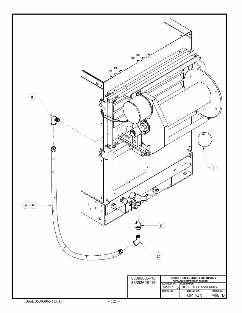
-- 121 --Book 35393065 (1/01)
HOSE REEL ASSEMBLY7/29/97
PORTABLE COMPRESSOR DIVISIONDESCRIPTION
MODEL NO.
INGERSOLL--RAND COMPANY
DATE/DWN BY:
bd
F
B
C
E
D
A
OPTION BMANUAL NO. DATE/REV:
4/98
35393065--1635393628--16
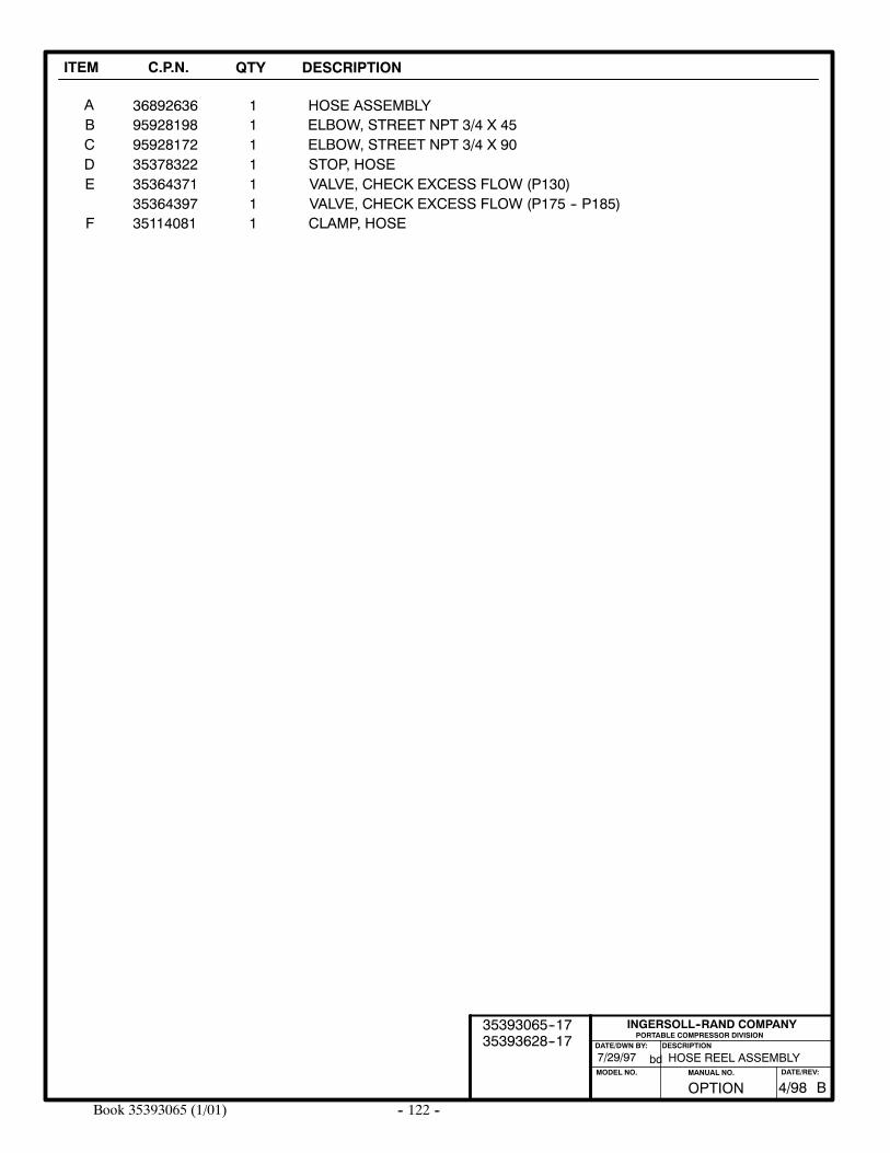
-- 122 --Book 35393065 (1/01)
ITEM C.P.N. QTY DESCRIPTION
AB
368926361
HOSE ASSEMBLY195928198 ELBOW, STREET NPT 3/4 X 45
PORTABLE COMPRESSOR DIVISIONDESCRIPTION
MODEL NO.
INGERSOLL--RAND COMPANY
DATE/DWN BY:
bd
CDE
95928172353783223536437135364397
1111
ELBOW, STREET NPT 3/4 X 90STOP, HOSEVALVE, CHECK EXCESS FLOW (P130)VALVE, CHECK EXCESS FLOW (P175 -- P185)
HOSE REEL ASSEMBLY7/29/97
F 35114081 1 CLAMP, HOSE
OPTION BMANUAL NO. DATE/REV:
4/98
35393065--1735393628--17
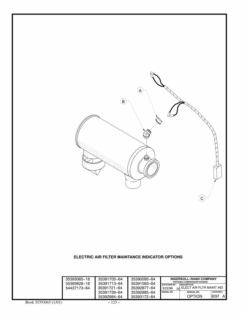
-- 123 --Book 35393065 (1/01)
A
B
ELECT AIR FLTR MAINT IND3/22/96
ELECTRIC AIR FILTER MAINTANCE INDICATOR OPTIONS
PORTABLE COMPRESSOR DIVISIONDESCRIPTION
MODEL NO.
INGERSOLL--RAND COMPANY
DATE/DWN BY:
bd
C
35393628--1835393065--18
35391713--6435391705--64
35391739--6435391721--64
35392984--64
35392877--6435392885--6435393172--64
35390095--6435391093--64
OPTION AMANUAL NO. DATE/REV:
8/97
54437173--64
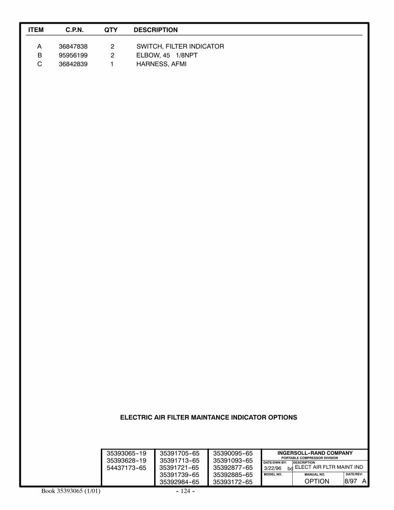
-- 124 --Book 35393065 (1/01)
ITEM C.P.N. QTY DESCRIPTION
A 36847838 2 SWITCH, FILTER INDICATORB 95956199 2 ELBOW, 45 1/8NPTC 36842839 1 HARNESS, AFMI
ELECT AIR FLTR MAINT IND3/22/96
PORTABLE COMPRESSOR DIVISIONDESCRIPTION
MODEL NO.
INGERSOLL--RAND COMPANY
DATE/DWN BY:
bd
ELECTRIC AIR FILTER MAINTANCE INDICATOR OPTIONS
35393628--1935393065--19
35391713--6535391705--65
35391739--6535391721--65
35392984--65
35392877--6535392885--6535393172--65
35390095--6535391093--65
OPTION AMANUAL NO. DATE/REV:
8/97
54437173--65
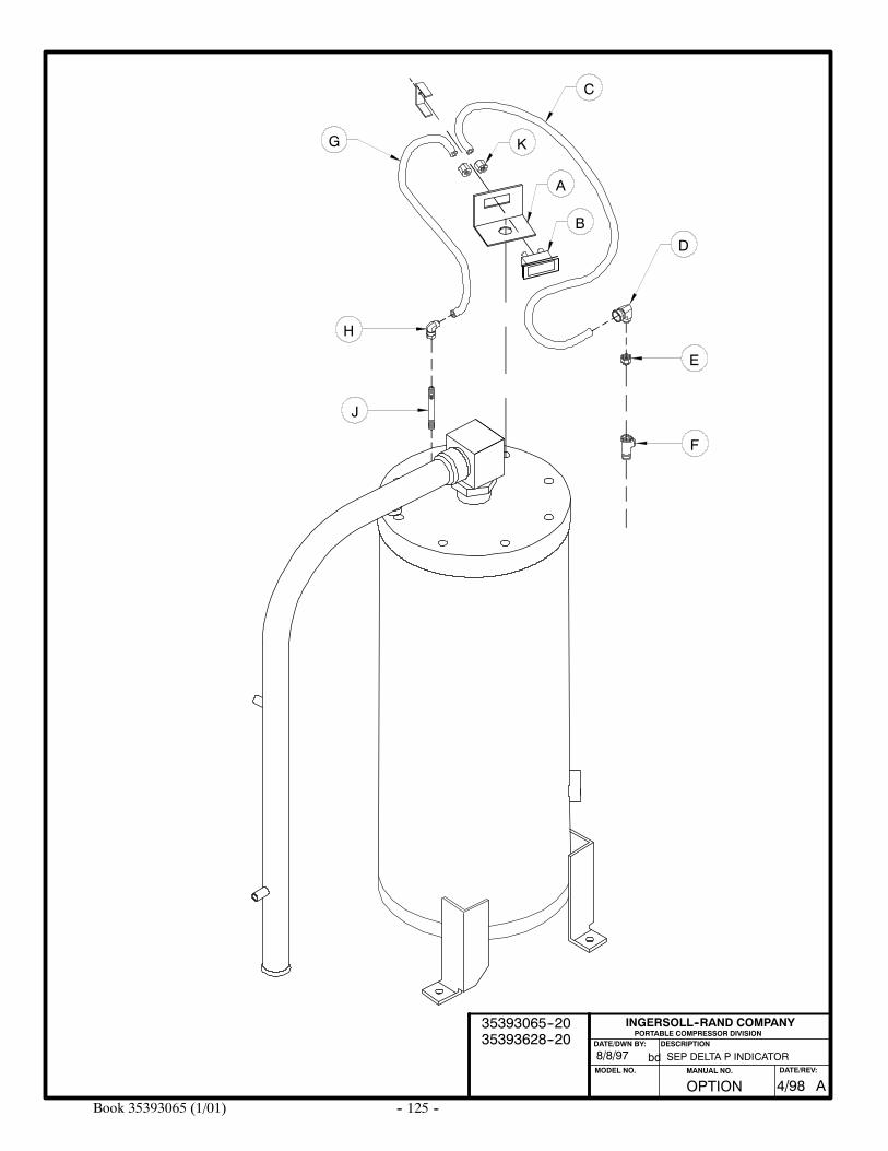
-- 125 --Book 35393065 (1/01)
SEP DELTA P INDICATOR8/8/97
PORTABLE COMPRESSOR DIVISIONDESCRIPTION
INGERSOLL--RAND COMPANY
DATE/DWN BY:
bd
A
B
C
D
E
F
G
H
J
K
OPTION AMANUAL NO. DATE/REV:
4/98
35393065--2035393628--20
MODEL NO.
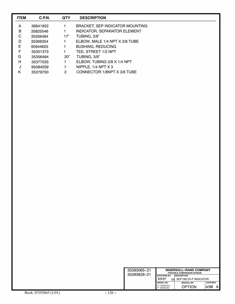
-- 126 --Book 35393065 (1/01)
ITEM C.P.N. QTY DESCRIPTION
ABCDE
35825546 1 INDICATOR, SEPARATOR ELEMENT1
FGH
3535648435369354 1 ELBOW, MALE 1/4 NPT X 3/8 TUBE
35377035 1 ELBOW, TUBING 3/8 X 1/4 NPT
PORTABLE COMPRESSOR DIVISIONDESCRIPTION
MODEL NO.
INGERSOLL--RAND COMPANY
DATE/DWN BY:
bd
P--185AWJDUP--130AWJDU --
35356484 20” TUBING, 3/8”
17” TUBING, 3/8”
36841922 BRACKET, SEP INDICATOR MOUNTING
95944625 1 BUSHING, REDUCING35301373 1 TEE, STREET 1/2 NPT
J 95084059 1 NIPPLE, 1/4 NPT X 3
SEP DELTA P INDICATOR8/8/97
K 35379700 2 CONNECTOR 1/8NPT X 3/8 TUBE
OPTION AMANUAL NO. DATE/REV:
4/98
35393065--2135393628--21
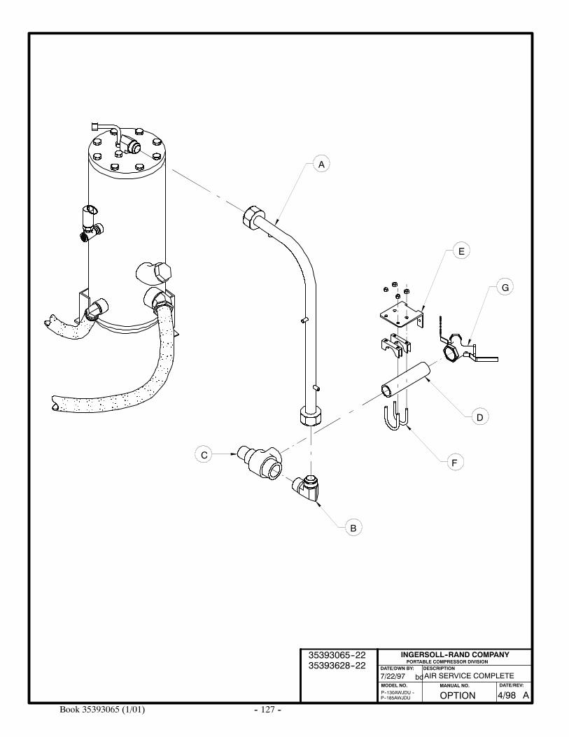
-- 127 --Book 35393065 (1/01)
AIR SERVICE COMPLETE
PORTABLE COMPRESSOR DIVISIONDESCRIPTION
MODEL NO.
INGERSOLL--RAND COMPANY
DATE/DWN BY:
bd7/22/97
P--185AWJDUP--130AWJDU --
A
E
G
D
F
B
C
OPTION AMANUAL NO. DATE/REV:
4/98
35393065--2235393628--22
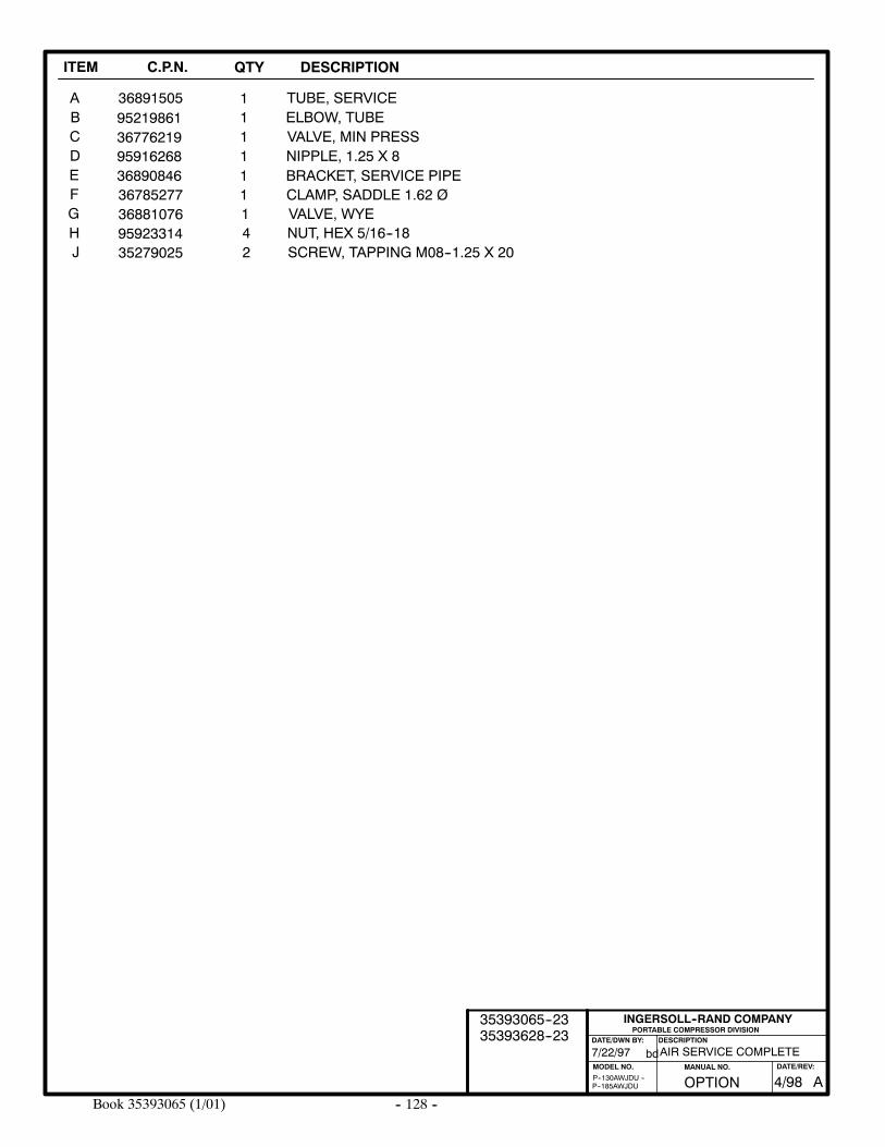
-- 128 --Book 35393065 (1/01)
ITEM C.P.N. QTY DESCRIPTION
ABCDE
95219861 1 ELBOW, TUBE1
FGH
3677621995916268 1 NIPPLE, 1.25 X 8
95923314 4 NUT, HEX 5/16--18
PORTABLE COMPRESSOR DIVISIONDESCRIPTION
MODEL NO.
INGERSOLL--RAND COMPANY
DATE/DWN BY:
bd
P--185AWJDUP--130AWJDU --
36881076 1 VALVE, WYE
AIR SERVICE COMPLETE
1 VALVE, MIN PRESS
7/22/97
36891505 TUBE, SERVICE
36890846 1 BRACKET, SERVICE PIPE36785277 1 CLAMP, SADDLE 1.62 Ø
J 35279025 2 SCREW, TAPPING M08--1.25 X 20
OPTION AMANUAL NO. DATE/REV:
4/98
35393065--2335393628--23
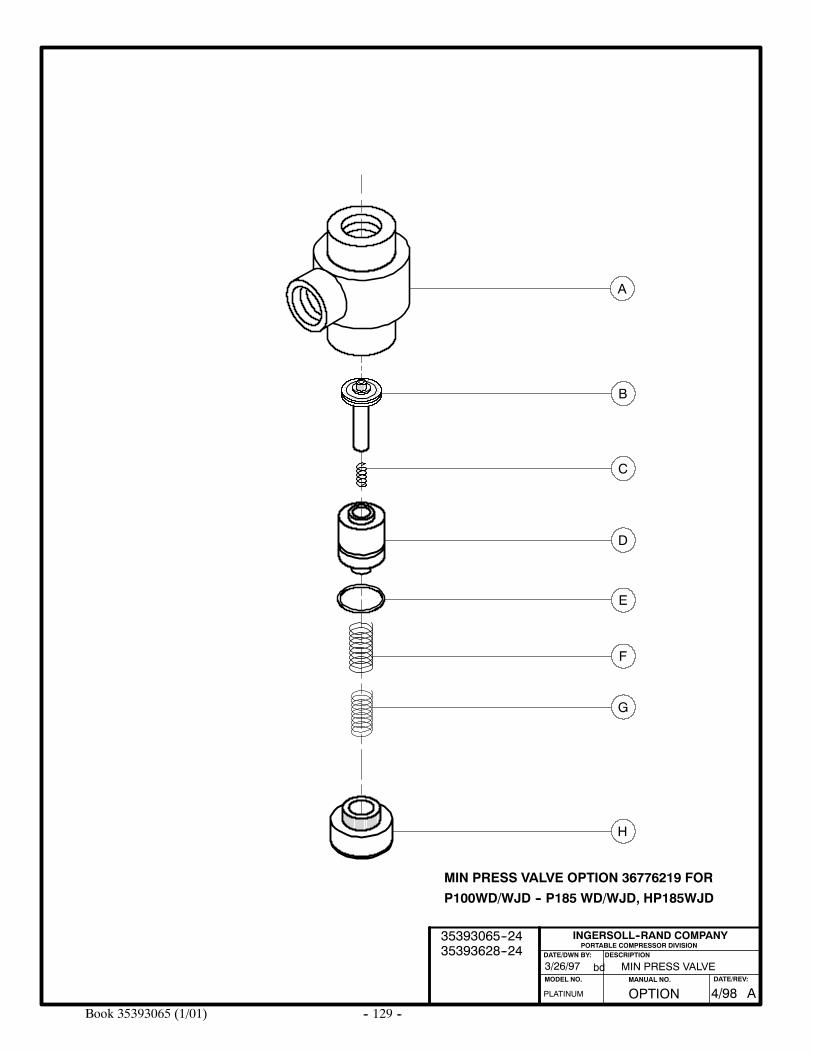
-- 129 --Book 35393065 (1/01)
A
B
C
D
E
F
MIN PRESS VALVE3/26/97
H
G
PLATINUM
PORTABLE COMPRESSOR DIVISIONDESCRIPTION
MODEL NO.
INGERSOLL--RAND COMPANY
DATE/DWN BY:
bd
MIN PRESS VALVE OPTION 36776219 FOR
P100WD/WJD -- P185 WD/WJD, HP185WJD
OPTION AMANUAL NO. DATE/REV:
4/98
35393065--2435393628--24
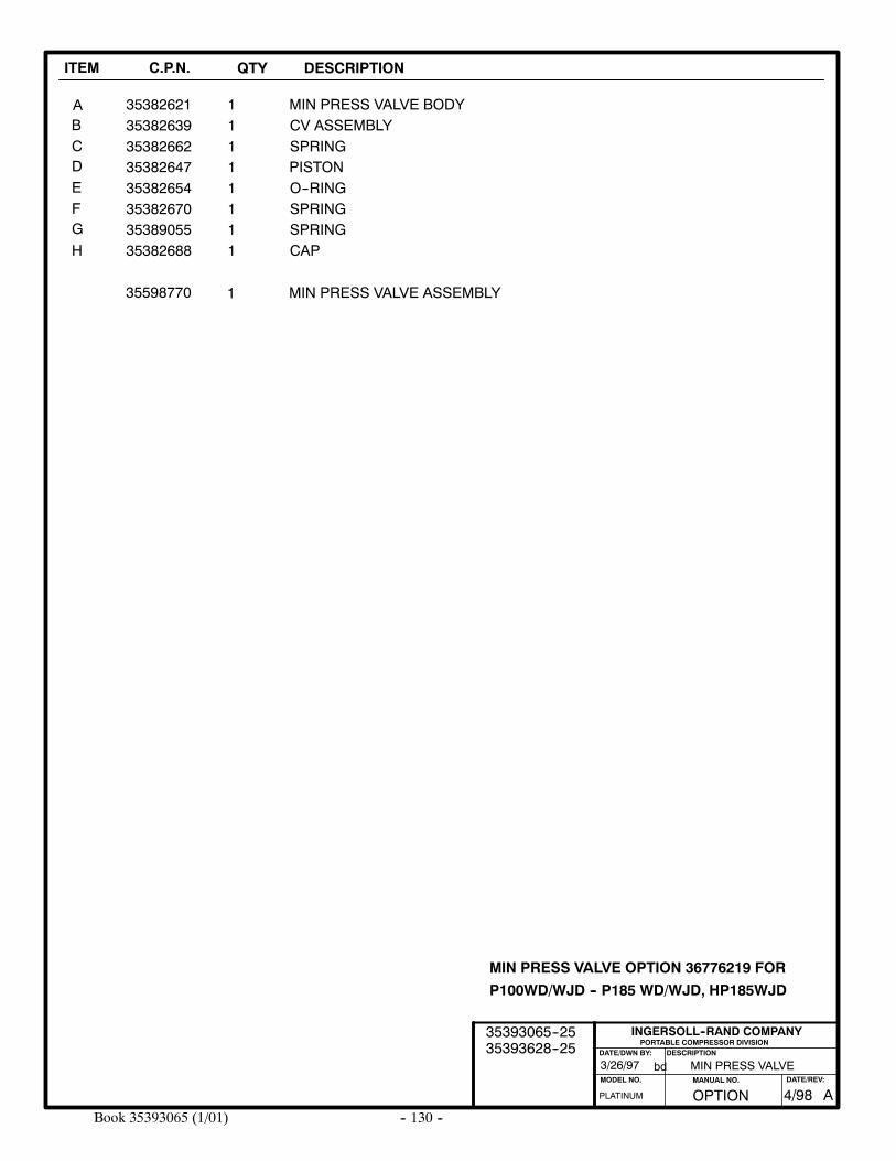
-- 130 --Book 35393065 (1/01)
ITEM C.P.N. QTY DESCRIPTION
MIN PRESS VALVE
ABCDEFG
3538262135382639
3538264735382654
35382662
35382670
111111
MIN PRESS VALVE BODYCV ASSEMBLYSPRINGPISTONO--RINGSPRING
35598770 1 MIN PRESS VALVE ASSEMBLY
H3538905535382688
11
SPRINGCAP
PORTABLE COMPRESSOR DIVISIONDESCRIPTION
MODEL NO.
INGERSOLL--RAND COMPANY
DATE/DWN BY:
bd3/26/97
PLATINUM
MIN PRESS VALVE OPTION 36776219 FOR
P100WD/WJD -- P185 WD/WJD, HP185WJD
OPTION AMANUAL NO. DATE/REV:
4/98
35393065--2535393628--25
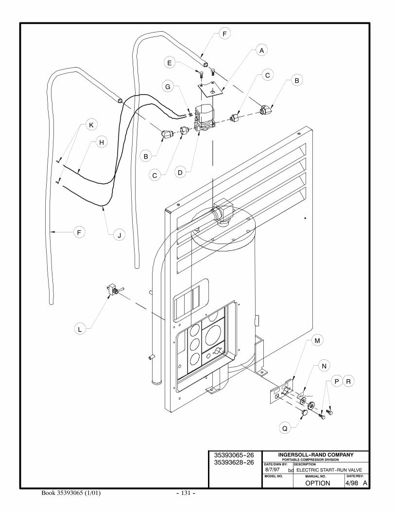
-- 131 --Book 35393065 (1/01)
ELECTRIC START--RUN VALVE8/7/97
PORTABLE COMPRESSOR DIVISIONDESCRIPTION
MODEL NO.
INGERSOLL--RAND COMPANY
DATE/DWN BY:
bd
A
BC
F
D
B
C
E
G
L
H
K
JF
M
PUSH AFTER WARM--UP
N
P
Q
R
OPTION AMANUAL NO. DATE/REV:
4/98
35393065--2635393628--26
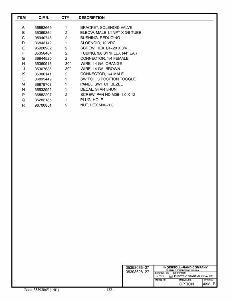
-- 132 --Book 35393065 (1/01)
ITEM C.P.N. QTY DESCRIPTION
AB
368926692
BRACKET, SOLENOID VALVE135369354 ELBOW, MALE 1/4NPT X 3/8 TUBE
PORTABLE COMPRESSOR DIVISIONDESCRIPTION
MODEL NO.
INGERSOLL--RAND COMPANY
DATE/DWN BY:
bd
CDEFGHJKLMNPQ
959407483684314295928982353564843684452035360916
36895449
3530768535306141
36879708365329923688220735282185
2122230”30”211121
BUSHING, REDUCINGSLOENOID, 12 VDCSCREW, HEX 1/4--20 X 3/4TUBING, 3/8 SYNFLEX (44” EA.)CONNECTOR, 1/4 FEMALEWIRE, 14 GA. ORANGEWIRE, 14 GA. BROWNCONNECTOR, 1/4 MALESWITCH, 3 POSITION TOGGLEPANEL, SWITCH BEZELDECAL, START/RUNSCREW, PAN HD M06--1.0 X 12PLUG, HOLE
ELECTRIC START--RUN VALVE8/7/97
R 96700851 2 NUT, HEX M06--1.0
OPTION BMANUAL NO. DATE/REV:
4/98
35393065--2735393628--27
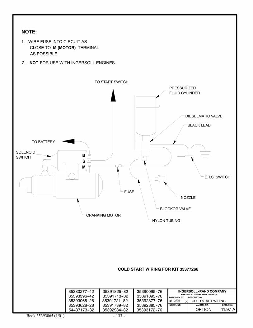
-- 133 --Book 35393065 (1/01)
COLD START WIRING
COLD START WIRING FOR KIT 35377266
BSM
BLACK LEAD
E.T.S. SWITCH
NOZZLE
DIESELMATIC VALVE
PRESSURIZEDFLUID CYLINDER
BLOCKOR VALVE
NYLON TUBING
FUSE
CRANKING MOTOR
TO BATTERY
TO START SWITCH
SOLENOIDSWITCH
NOTE:
1. WIRE FUSE INTO CIRCUIT ASCLOSE TO M (MOTOR) TERMINALAS POSSIBLE.
PORTABLE COMPRESSOR DIVISIONDESCRIPTION
MODEL NO.
INGERSOLL--RAND COMPANY
DATE/DWN BY:
bd4/12/9635393065--2835393396--4235380277--42
35391713--8235391825--82
35391739--8235391721--82
35392984--82
35392877--7635392885--7635393172--76
35390095--7635391093--76
OPTION AMANUAL NO. DATE/REV:
11/9735393628--28
2. NOT FOR USE WITH INGERSOLL ENGINES.
54437173--82
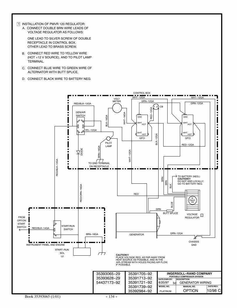
-- 134 --Book 35393065 (1/01)
GENERATOR WIRING
PORTABLE COMPRESSOR DIVISIONDESCRIPTION
MODEL NO.
INGERSOLL--RAND COMPANY
DATE/DWN BY:
bd8/20/97
1 INSTALLATION OF PMVR 120 REGULATOR:A. CONNECT DOUBLE BRN WIRE LEADS OF
VOLTAGE REGULATOR AS FOLLOWS:
ONE LEAD TO SILVER SCREW OF DOUBLERECEPTACLE IN CONTROL BOX.OTHER LEAD TO BRASS SCREW.
B.
C.
D.
CONNECT RED WIRE TO YELLOW WIRE(HOT +12 V SOURCE), AND TO PILOT LAMPTERMINAL.
CONNECT BLUE WIRE TO GREEN WIRE OFALTERNATOR WITH BUTT SPLICE.
CONNECT BLACK WIRE TO BATTERY NEG.
WHT--16G
A
BLK
--16G
A
BRN--16G
A
DIODE
1
INSTRUMENT PANEL AND ENGINE
RED/BLK--14GA
START--RUNSOLL2
BRN--16GA
RED/ORN--16G
A
START/RUNSWITCH
RED/BLK
--12G
A
GEN/AIRSWITCH
RED/BLK--12GA
YEL--12GA
VOLTMETER
PILOTLAMP
TO GND TERMINALON RECEPTACLE
WHT--12G
A
RED
GFCI
HOTWHT
HOTWHT
GND
CONTROL BOX
WHT--12GA
GRN--12GA
RED--12G
A 1 2 CB
BLK
--12G
A
BRN
BLK
BRN
BLU
E
GRN
BUTT SPLICE
GFCI
HOTWHT
HOTWHT
GND
RED--12GA
VOLTAGEREGULATOR
MPMVR120
TO BATTERY (NEG.)CAUTION!!!DO NOT GND LOCALLY,GO TO BATTERY NEG.
GENERATOR GRN--12GA
CHASSISGND
CAUTION!!!PLACE VOLTAGE REG. AS FAR AWAY FROMHEAT SOURCE AS POSSIBLE, AND IN THEAIR--STREAM WITH HOLES FACING AIR FLOW,IF POSSIBLE.
WHT--12GA
GRN--12GA
FROMOFF/ONSTARTSWITCH
PLATINUM
35391721--9235391739--9235392984--92
35391705--9235391713--92
OPTIONMANUAL NO. DATE/REV:
C10/98
35393065--2935393628--2954437173--92
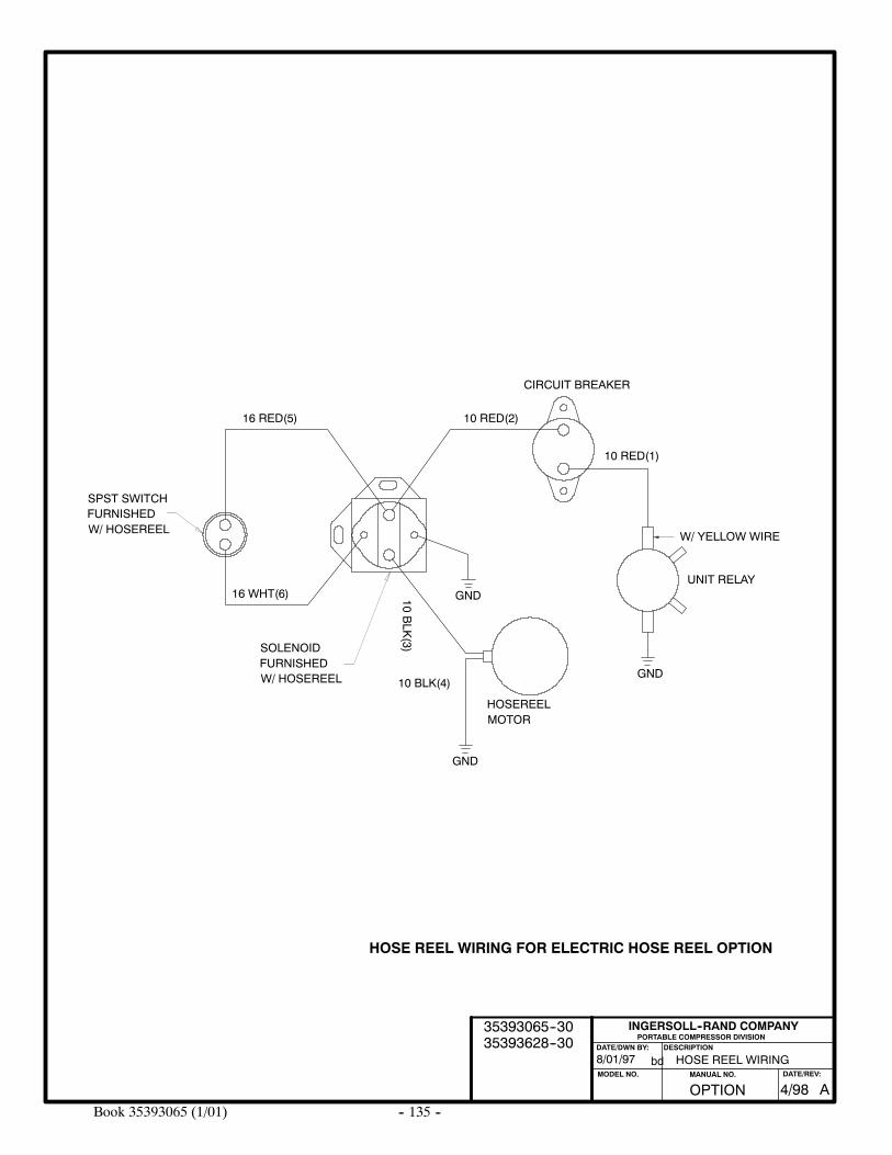
-- 135 --Book 35393065 (1/01)
HOSE REEL WIRING
HOSE REEL WIRING FOR ELECTRIC HOSE REEL OPTION
PORTABLE COMPRESSOR DIVISIONDESCRIPTION
MODEL NO.
INGERSOLL--RAND COMPANY
DATE/DWN BY:
bd8/01/97
GND
GND
GND
CIRCUIT BREAKER
HOSEREEL
16 WHT(6)
16 RED(5)
10BLK
(3)
10 BLK(4)
10 RED(2)
10 RED(1)
UNIT RELAY
W/ YELLOW WIRE
SOLENOIDFURNISHEDW/ HOSEREEL
SPST SWITCHFURNISHEDW/ HOSEREEL
MOTOR
OPTION AMANUAL NO. DATE/REV:
4/98
35393065--3035393628--30
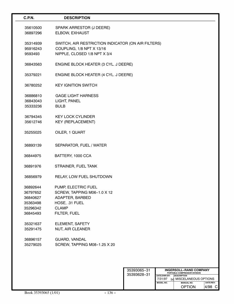
-- 136 --Book 35393065 (1/01)
7/31/97 MISCELANEOUS OPTIONS
C.P.N. DESCRIPTION
35610500
35314939 SWITCH, AIR RESTRICTION INDICATOR (ON AIR FILTERS)
36843563 ENGINE BLOCK HEATER (3 CYL. J DEERE)
35379221 ENGINE BLOCK HEATER (4 CYL. J DEERE)
36780252 KEY IGNITION SWITCH
3688681036843043
GAGE LIGHT HARNESSLIGHT, PANEL
3679434535612746
KEY LOCK CYLINDERKEY (REPLACEMENT)
35255025
36893139
OILER, 1 QUART
SEPARATOR, FUEL / WATER
36844975 BATTERY, 1000 CCA
36856979 RELAY, LOW FUEL SHUTDOWN
36892644 PUMP, ELECTRIC FUEL
PORTABLE COMPRESSOR DIVISIONDESCRIPTION
MODEL NO.
INGERSOLL--RAND COMPANY
DATE/DWN BY:
bd
ELBOW, EXHAUST36897296SPARK ARRESTOR (J DEERE)
36891976 STRAINER, FUEL TANK
35333236 BULB
3532163735291475
ELEMENT, SAFETYNUT, AIR CLEANER
95916243 COUPLING, 1/8 NPT X 13/169593493 NIPPLE, CLOSED 1/8 NPT X 3/4
36797652 SCREW, TAPPING M06--1.0 X 1236840627 ADAPTER, BARBED35363498 HOSE, .31 FUEL35296342 CLAMP36845493 FILTER, FUEL
3689615735279025
GUARD, VANDALSCREW, TAPPING M08--1.25 X 20
OPTION CMANUAL NO. DATE/REV:
4/98
35393065--3135393628--31
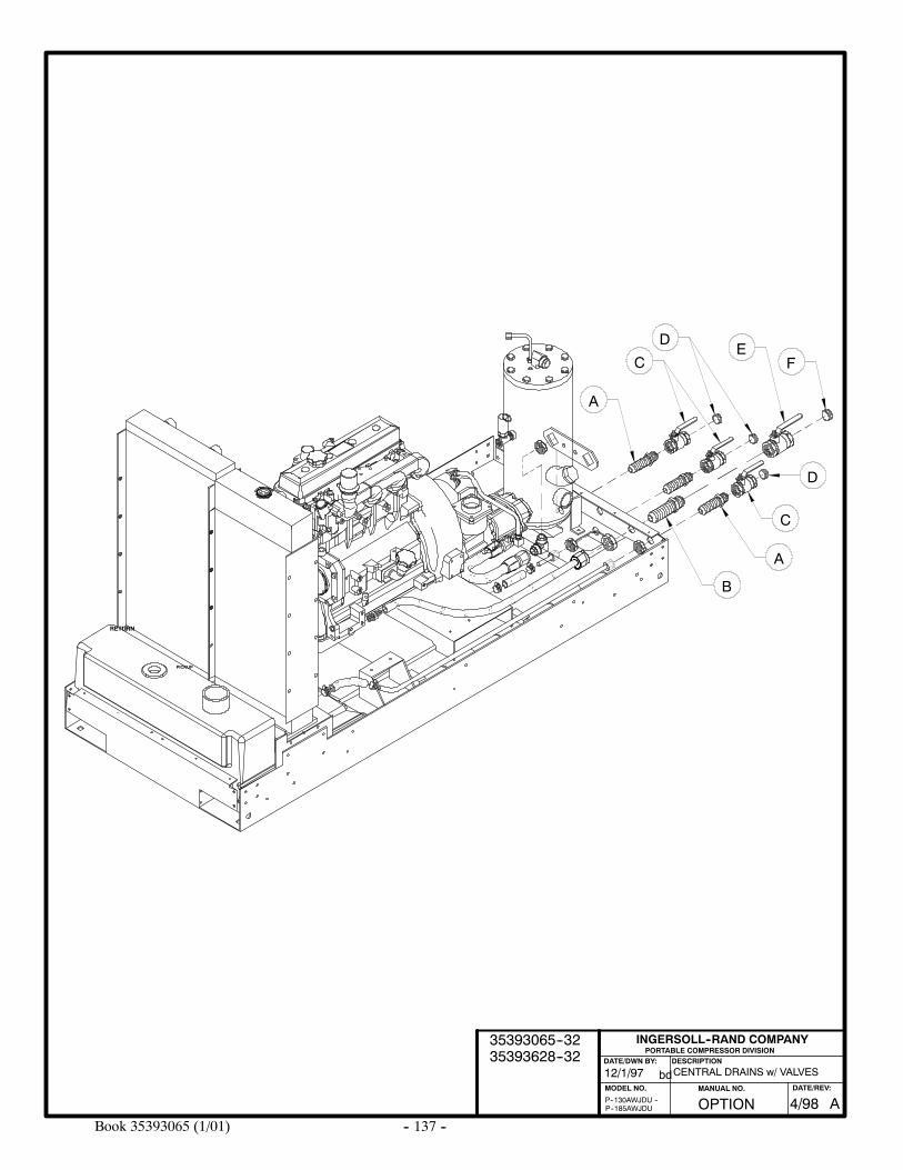
-- 137 --Book 35393065 (1/01)
CENTRAL DRAINS w/ VALVES12/1/97
P--130AWJDU --P--185AWJDU
PORTABLE COMPRESSOR DIVISIONDESCRIPTION
MODEL NO.
INGERSOLL--RAND COMPANY
DATE/DWN BY:
bd
RETURN
PICKUP
A
B
C
D
A
CE
D
F
OPTION AMANUAL NO. DATE/REV:
4/98
35393065--3235393628--32
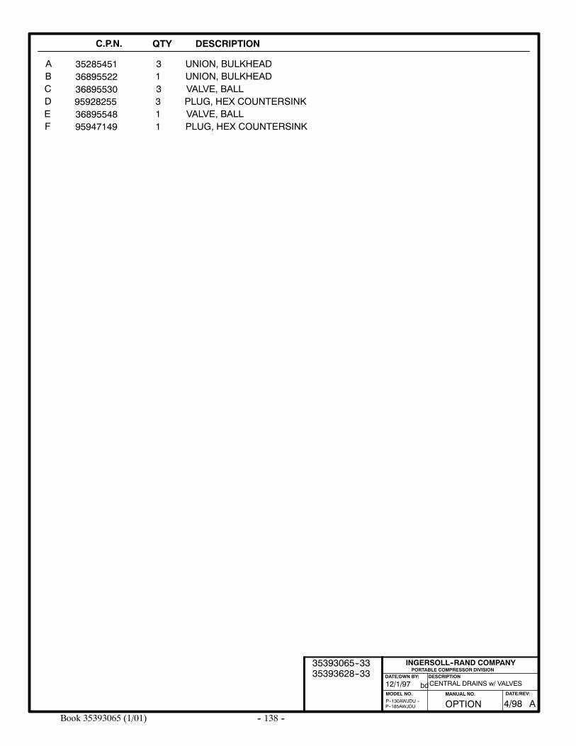
-- 138 --Book 35393065 (1/01)
C.P.N. QTY DESCRIPTION
ABCDEF
36895522 1 UNION, BULKHEAD35285451 3 UNION, BULKHEAD
PORTABLE COMPRESSOR DIVISIONDESCRIPTION
MODEL NO.
INGERSOLL--RAND COMPANY
DATE/DWN BY:
bd
P--185AWJDUP--130AWJDU --
36895530 3 VALVE, BALL
95947149 1 PLUG, HEX COUNTERSINK36895548 1 VALVE, BALL
CENTRAL DRAINS w/ VALVES12/1/97
95928255 3 PLUG, HEX COUNTERSINK
OPTION AMANUAL NO. DATE/REV:
4/98
35393065--3335393628--33
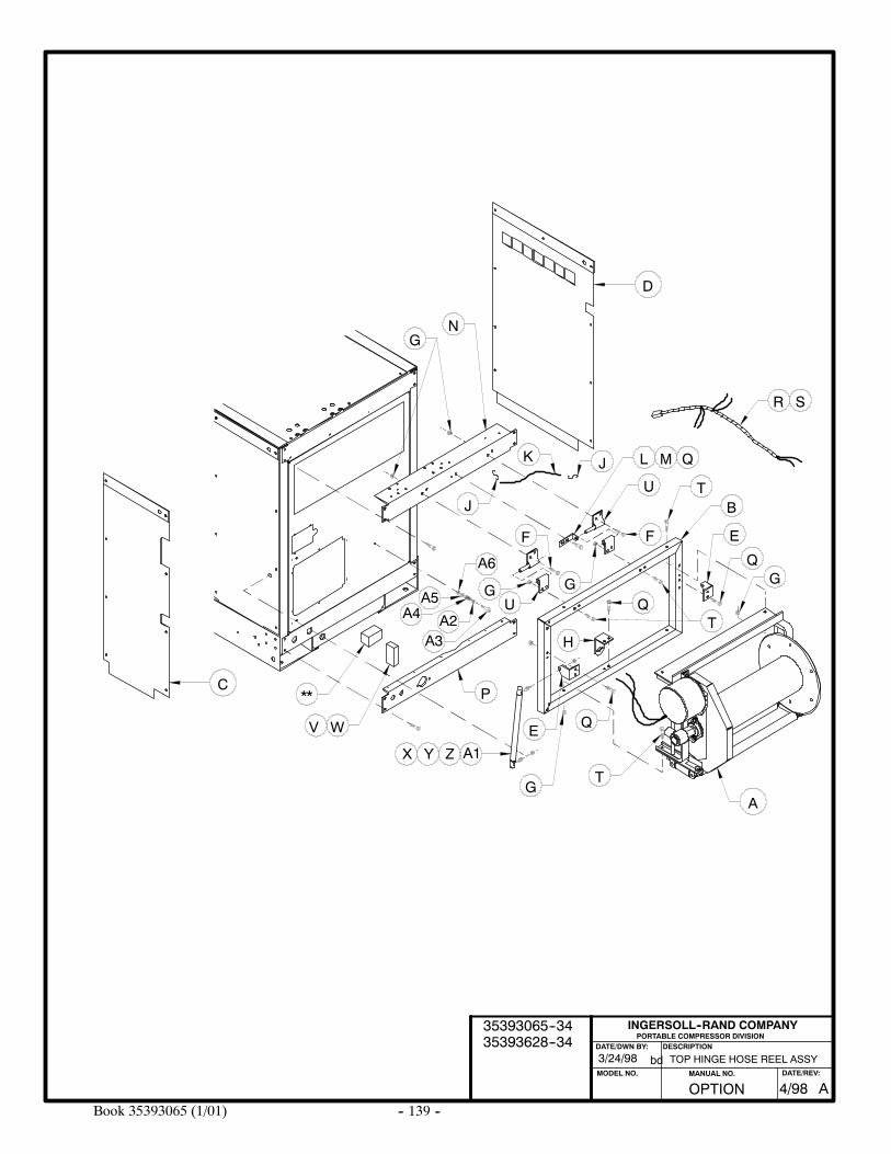
-- 139 --Book 35393065 (1/01)
PORTABLE COMPRESSOR DIVISIONDESCRIPTION
MODEL NO.
INGERSOLL--RAND COMPANY
DATE/DWN BY:
bd TOP HINGE HOSE REEL ASSY3/24/98
A
C
D
A6
R
TB
E
Q
QG
P
JK
NG
S
Q
T
H
A1
E
ZYX
GU
T
J
G
M
A5A4
A3A2
WV
F
U
L
F
Q
**
G
OPTION AMANUAL NO. DATE/REV:
4/98
35393065--3435393628--34
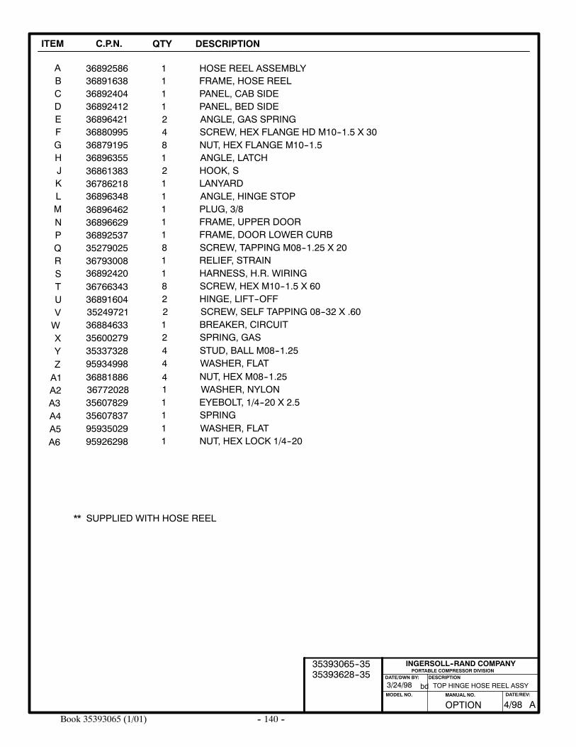
-- 140 --Book 35393065 (1/01)
ITEM C.P.N. QTY DESCRIPTION
AB
368925861
HOSE REEL ASSEMBLY136891638 FRAME, HOSE REEL
PORTABLE COMPRESSOR DIVISIONDESCRIPTION
MODEL NO.
INGERSOLL--RAND COMPANY
DATE/DWN BY:
bd
CDEFGHJKLMNPQRSTUVWX
368924043689241236896421368809953687919536896355
36896348
3686138336786218
3689646236896629368925373527902536793008
95934998
11248121111181
4
PANEL, CAB SIDEPANEL, BED SIDEANGLE, GAS SPRINGSCREW, HEX FLANGE HD M10--1.5 X 30NUT, HEX FLANGE M10--1.5ANGLE, LATCHHOOK, SLANYARDANGLE, HINGE STOPPLUG, 3/8FRAME, UPPER DOORFRAME, DOOR LOWER CURBSCREW, TAPPING M08--1.25 X 20RELIEF, STRAIN
WASHER, FLAT
36892420
35249721
3676634336891604
2
182
SCREW, SELF TAPPING 08--32 X .60
HARNESS, H.R. WIRINGSCREW, HEX M10--1.5 X 60HINGE, LIFT--OFF
35600279 2 SPRING, GAS
Y
4 NUT, HEX M08--1.2536881886
36884633 1 BREAKER, CIRCUIT
** SUPPLIED WITH HOSE REEL
Z35337328 4 STUD, BALL M08--1.25
TOP HINGE HOSE REEL ASSY3/24/98
A1A2A3A4
95926298 1 NUT, HEX LOCK 1/4--20
36772028 1 WASHER, NYLON
35607837 1 SPRING
A5
35607829 1 EYEBOLT, 1/4--20 X 2.5
A695935029 1 WASHER, FLAT
OPTION AMANUAL NO. DATE/REV:
4/98
35393065--3535393628--35
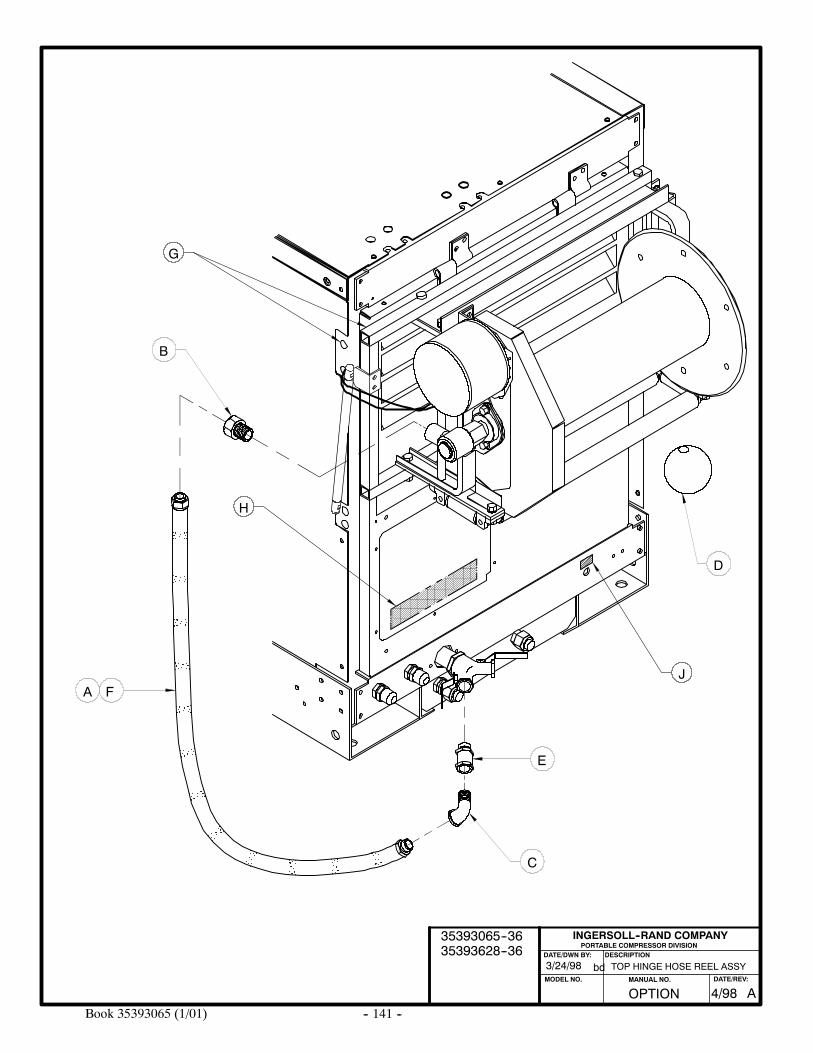
-- 141 --Book 35393065 (1/01)
PORTABLE COMPRESSOR DIVISIONDESCRIPTION
MODEL NO.
INGERSOLL--RAND COMPANY
DATE/DWN BY:
bd
F
B
C
E
D
A
TOP HINGE HOSE REEL ASSY3/24/98
H
J
G
OPTION AMANUAL NO. DATE/REV:
4/98
35393065--3635393628--36
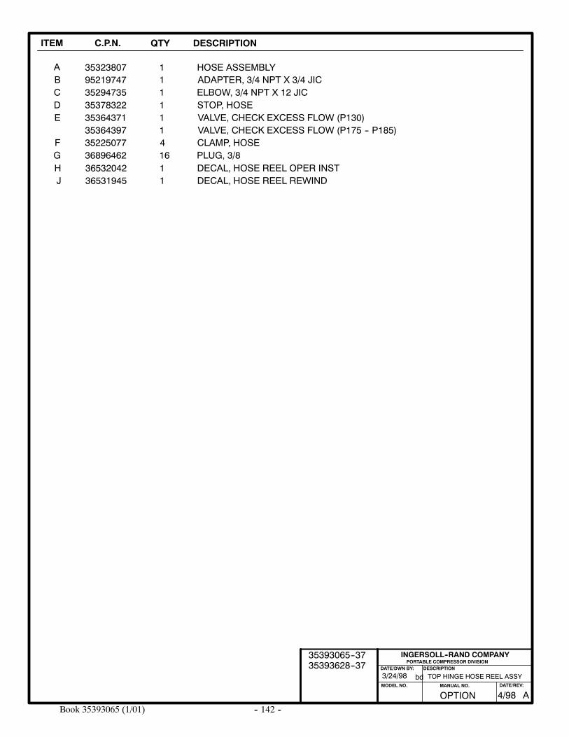
-- 142 --Book 35393065 (1/01)
ITEM C.P.N. QTY DESCRIPTION
AB
353238071
HOSE ASSEMBLY195219747 ADAPTER, 3/4 NPT X 3/4 JIC
PORTABLE COMPRESSOR DIVISIONDESCRIPTION
MODEL NO.
INGERSOLL--RAND COMPANY
DATE/DWN BY:
bd
CDE
35294735353783223536437135364397
1111
ELBOW, 3/4 NPT X 12 JICSTOP, HOSEVALVE, CHECK EXCESS FLOW (P130)VALVE, CHECK EXCESS FLOW (P175 -- P185)
F 35225077 4 CLAMP, HOSEG 36896462 16 PLUG, 3/8H 36532042 1 DECAL, HOSE REEL OPER INSTJ 36531945 1 DECAL, HOSE REEL REWIND
TOP HINGE HOSE REEL ASSY3/24/98
OPTION AMANUAL NO. DATE/REV:
4/98
35393065--3735393628--37
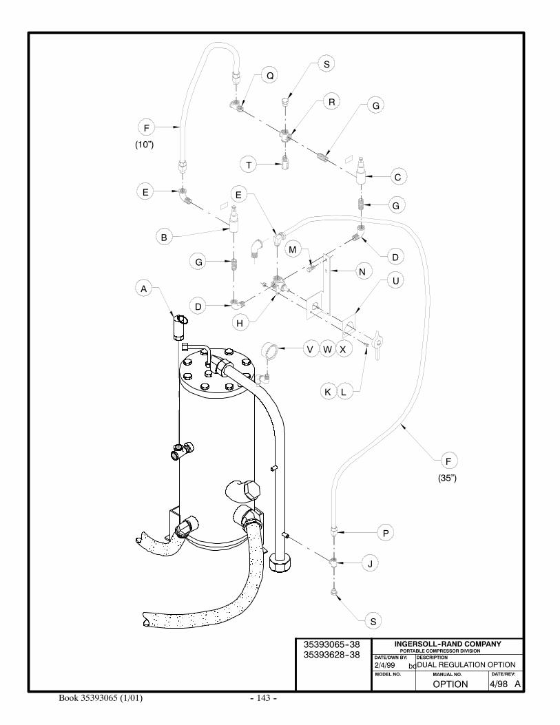
-- 143 --Book 35393065 (1/01)
DUAL REGULATION OPTION
PORTABLE COMPRESSOR DIVISIONDESCRIPTION
MODEL NO.
INGERSOLL--RAND COMPANY
DATE/DWN BY:
bd2/4/99
Q
G
D
F
S
D
J
P
H
LK
G
E
S
R
TC
GE
MB
AU
F
N
V W X
(10”)
(35”)
OPTION AMANUAL NO. DATE/REV:
4/98
35393065--3835393628--38
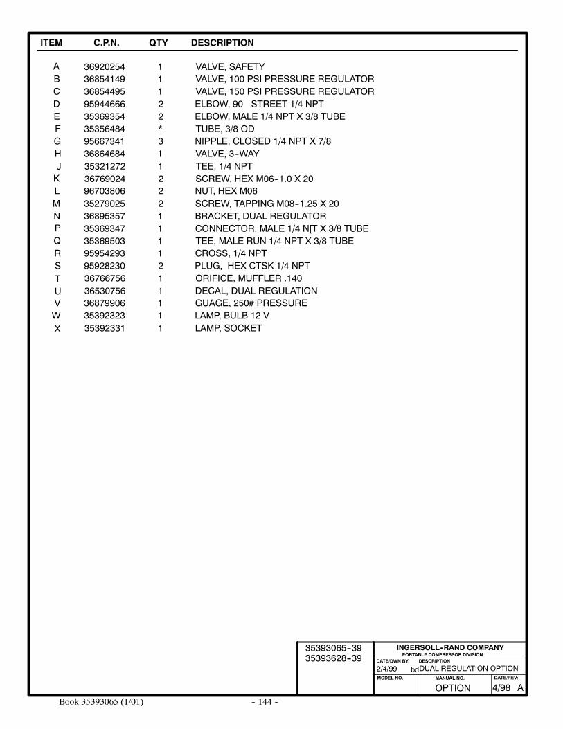
-- 144 --Book 35393065 (1/01)
ITEM C.P.N. QTY DESCRIPTION
AB
369202541
VALVE, SAFETY136854149 VALVE, 100 PSI PRESSURE REGULATOR
PORTABLE COMPRESSOR DIVISIONDESCRIPTION
MODEL NO.
INGERSOLL--RAND COMPANY
DATE/DWN BY:
bd
CDE
36854495959446663536935435356484
122*
VALVE, 150 PSI PRESSURE REGULATORELBOW, 90 STREET 1/4 NPTELBOW, MALE 1/4 NPT X 3/8 TUBETUBE, 3/8 ODF
95667341 3 NIPPLE, CLOSED 1/4 NPT X 7/8G36864684 1 VALVE, 3--WAYH35321272 1 TEE, 1/4 NPTJ36769024 2 SCREW, HEX M06--1.0 X 20K
ML
NPQRS
296703806 NUT, HEX M0635279025368953573536934735369503
2111
SCREW, TAPPING M08--1.25 X 20BRACKET, DUAL REGULATORCONNECTOR, MALE 1/4 N[T X 3/8 TUBETEE, MALE RUN 1/4 NPT X 3/8 TUBE
95954293 1 CROSS, 1/4 NPT95928230 2 PLUG, HEX CTSK 1/4 NPT36766756 1 ORIFICE, MUFFLER .14036530756 1 DECAL, DUAL REGULATION
TUVW
36879906 1 GUAGE, 250# PRESSURE35392323 1 LAMP, BULB 12 V35392331 1 LAMP, SOCKETX
DUAL REGULATION OPTION2/4/99
OPTION AMANUAL NO. DATE/REV:
4/98
35393065--3935393628--39
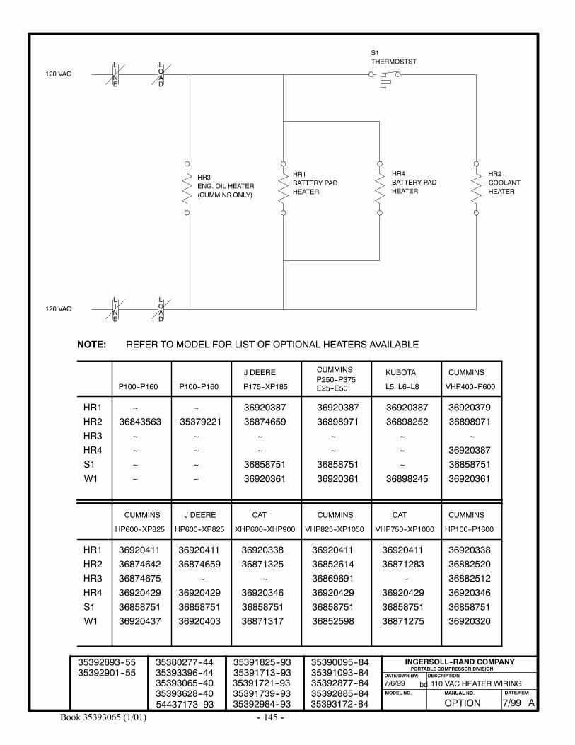
-- 145 --Book 35393065 (1/01)
110 VAC HEATER WIRING
PORTABLE COMPRESSOR DIVISIONDESCRIPTION
MODEL NO.
INGERSOLL--RAND COMPANY
DATE/DWN BY:
bd7/6/9935393065--4035393396--4435380277--44
35391713--9335391825--93
35391739--9335391721--93
35392984--93
35392877--8435392885--8435393172--84
35390095--8435391093--84
OPTION AMANUAL NO. DATE/REV:
7/9935393628--40
LINE
LOAD
120 VAC
120 VAC
ENG. OIL HEATER(CUMMINS ONLY)
BATTERY PADHEATER
BATTERY PADHEATER
COOLANTHEATER
S1THERMOSTST
HR3 HR2HR1 HR4
LINE
LOAD
35392901--5535392893--55
HR1
HR2
HR3
HR4
S1
W1
36920387
36920411
P100--P160 P100--P160 P175--XP185 E25--E50 L5; L6--L8 VHP400--P600
J DEERE CUMMINS KUBOTA CUMMINS
CUMMINS
HP600--XP825
J DEERE
HP600--XP825
CAT
XHP600--XHP900
CUMMINS
VHP825--XP1050
CAT
VHP750--XP1000
CUMMINS
HP100--P1600
P250--P375
~
~
~
~
~ ~
~
~
~
~
~
~ ~
~
~
~
~
~
~ ~ ~
36920411 3692041136920411 36920338 36920338
36920387
36843563 35379221 36874659 36898971 36898252 36898971
36920361 36920361 36898245
36858751 36858751 36858751
36858751 3685875136858751 36858751 36858751 36858751
36920437 36852598 36871275 36920320
36920429 36920429 36920429 36920346
36874675 36869691 36882512
36874642 36852614 36871283 36882520
36920429 36920346
36920361
36920403 36871317
36874659 36871325
REFER TO MODEL FOR LIST OF OPTIONAL HEATERS AVAILABLENOTE:
HR1
HR2
HR3
HR4
S1
W1
3692037936920387
36920387
54437173--93