operating instructions - vegabar 17
TRANSCRIPT

Operating InstructionsVEGABAR 17
Document ID:27636
Process pressure

Contents
1 About this document
1.1 Function. . . . . . . . . . . . . . . . . . . . . . . . . . . . . . . . . . 4
1.2 Target group . . . . . . . . . . . . . . . . . . . . . . . . . . . . . . 4
1.3 Symbolism used. . . . . . . . . . . . . . . . . . . . . . . . . . . . 4
2 For your safety
2.1 Authorised personnel . . . . . . . . . . . . . . . . . . . . . . . . 5
2.2 Appropriate use . . . . . . . . . . . . . . . . . . . . . . . . . . . . 5
2.3 Warning about misuse . . . . . . . . . . . . . . . . . . . . . . . 5
2.4 General safety instructions . . . . . . . . . . . . . . . . . . . . 5
2.5 Safety label on the instrument . . . . . . . . . . . . . . . . . . 6
2.6 CE conformity . . . . . . . . . . . . . . . . . . . . . . . . . . . . . 6
2.7 Measuring range - permissible process pressure . . . . 6
2.8 Safety instructions for Ex areas . . . . . . . . . . . . . . . . . 6
2.9 Environmental instructions. . . . . . . . . . . . . . . . . . . . . 6
3 Product description
3.1 Structure . . . . . . . . . . . . . . . . . . . . . . . . . . . . . . . . . 7
3.2 Principle of operation . . . . . . . . . . . . . . . . . . . . . . . . 8
3.3 Operation. . . . . . . . . . . . . . . . . . . . . . . . . . . . . . . . . 8
3.4 Packaging, transport and storage . . . . . . . . . . . . . . . 8
4 Mounting
4.1 General instructions . . . . . . . . . . . . . . . . . . . . . . . . . 10
4.2 Instructions for installation . . . . . . . . . . . . . . . . . . . . . 10
4.3 Mounting steps. . . . . . . . . . . . . . . . . . . . . . . . . . . . . 10
5 Connecting to power supply
5.1 Preparing the connection . . . . . . . . . . . . . . . . . . . . . 12
5.2 Connection procedure. . . . . . . . . . . . . . . . . . . . . . . . 13
5.3 Wiring plan. . . . . . . . . . . . . . . . . . . . . . . . . . . . . . . . 16
6 Set up
6.1 Setup steps . . . . . . . . . . . . . . . . . . . . . . . . . . . . . . . 18
6.2 Recalibration . . . . . . . . . . . . . . . . . . . . . . . . . . . . . . 18
7 Maintenance and fault rectification
7.1 Maintenance . . . . . . . . . . . . . . . . . . . . . . . . . . . . . . 22
7.2 Remove interferences . . . . . . . . . . . . . . . . . . . . . . . . 22
7.3 Instrument repair . . . . . . . . . . . . . . . . . . . . . . . . . . . 23
8 Dismounting
8.1 Dismounting steps . . . . . . . . . . . . . . . . . . . . . . . . . . 24
8.2 Disposal . . . . . . . . . . . . . . . . . . . . . . . . . . . . . . . . . 24
9 Supplement
9.1 Technical data . . . . . . . . . . . . . . . . . . . . . . . . . . . . . 25
9.2 Dimensions . . . . . . . . . . . . . . . . . . . . . . . . . . . . . . . 31
2 VEGABAR 17
Contents27636-EN-110921

Supplementary documentation
Information:
Supplementary documents appropriate to the ordered version comewith the delivery. You can find them listed in chapter "Productdescription".
Instructions manuals for accessories and replacement parts
Tip:
To ensure reliable setup and operation of your VEGABAR 17, we offeraccessories and replacement parts. The corresponding documenta-tions are:
l 32036 - Welded socket and seals
Editing status: 2011-09-16
VEGABAR 17 3
Contents27636-EN-110921

1 About this document
1.1 Function
This operating instructions manual provides all the information youneed for mounting, connection and setup as well as importantinstructions for maintenance and fault rectification. Please read thisinformation before putting the instrument into operation and keep thismanual accessible in the immediate vicinity of the device.
1.2 Target group
This operating instructions manual is directed to trained qualifiedpersonnel. The contents of this manual should be made available tothese personnel and put into practice by them.
1.3 Symbolism used
Information, tip, note
This symbol indicates helpful additional information.
Caution: If this warning is ignored, faults or malfunctions canresult.Warning: If this warning is ignored, injury to persons and/or seriousdamage to the instrument can result.Danger: If this warning is ignored, serious injury to persons and/ordestruction of the instrument can result.
Ex applications
This symbol indicates special instructions for Ex applications.
l List
The dot set in front indicates a list with no implied sequence.
à Action
This arrow indicates a single action.
1 Sequence
Numbers set in front indicate successive steps in a procedure.
4 VEGABAR 17
1 About this document27636-EN-110921

2 For your safety
2.1 Authorised personnel
All operations described in this operating instructions manual must becarried out only by trained specialist personnel authorised by the plantoperator.
During work on and with the device the required personal protectiveequipment must always be worn.
2.2 Appropriate use
VEGABAR 17 is a pressure transmitter for measurement of gaugepressure, absolute pressure and vacuum.
You can find detailed information on the application range in chapter"Product description".
Operational reliability is ensured only if the instrument is properly usedaccording to the specifications in the operating instructions manual aswell as possible supplementary instructions.
For safety and warranty reasons, any invasive work on the devicebeyond that described in the operating instructions manual may becarried out only by personnel authorised by the manufacturer. Arbitraryconversions or modifications are explicitly forbidden.
2.3 Warning about misuse
Inappropriate or incorrect use of the instrument can give rise toapplication-specific hazards, e.g. vessel overfill or damage to systemcomponents through incorrect mounting or adjustment.
2.4 General safety instructions
This is a high-tech instrument requiring the strict observance ofstandard regulations and guidelines. The user must take note of thesafety instructions in this operating instructions manual, the country-specific installation standards as well as all prevailing safetyregulations and accident prevention rules.
The instrument must only be operated in a technically flawless andreliable condition. The operator is responsible for trouble-freeoperation of the instrument.
During the entire duration of use, the user is obliged to determine thecompliance of the necessary occupational safety measures with thecurrent valid rules and regulations and also take note of newregulations.
VEGABAR 17 5
2 For your safety27636-EN-110921

2.5 Safety label on the instrument
The safety approval markings and safety tips on the device must beobserved.
2.6 CE conformity
This device fulfills the legal requirements of the applicable EC
guidelines. By attaching the CE mark, VEGA provides a confirmationof successful testing. You can find the CE conformity declaration in thedownload area of www.vega.com.
The instrument is designed for use in an industrial environment.Nevertheless, electromagnetic interference from electrical conductorsand radiated emissions must be taken into account, as is usual with aclass A instrument according to EN 61326. If the instrument is used ina different environment, the electromagnetic compatibility to otherinstruments must be ensured by suitable measures.
2.7 Measuring range - permissible process pres-
sure
Due to the application, a measuring cell with a measuring range higherthan the permissible pressure range of the process fitting may havebeen integrated. The permissible process pressure is stated with"Process pressure" on the type label, see chapter 3.1 "Configuration".
For safety reasons, this range must not be exceeded.
2.8 Safety instructions for Ex areas
Please note the Ex-specific safety information for installation andoperation in Ex areas. These safety instructions are part of theoperating instructions manual and come with the Ex-approvedinstruments.
2.9 Environmental instructions
Protection of the environment is one of our most important duties. Thatis why we have introduced an environment management system withthe goal of continuously improving company environmental protection.The environment management system is certified according to DIN
EN ISO 14001.
Please help us fulfil this obligation by observing the environmentalinstructions in this manual:
l Chapter "Packaging, transport and storage"
l Chapter "Disposal"
6 VEGABAR 17
2 For your safety27636-EN-110921

3 Product description
3.1 Structure
The scope of delivery encompasses:
l VEGABAR 17 process pressure transmitterl Depending on the version, with plug connector, connection cable
or terminal housingl Documentation
- this operating instructions manual- Ex-specific "Safety instructions" (with Ex versions)- if necessary, further certificates
4
3
2
1
Fig. 1: VEGABAR 17 with plug connector according to ISO 4400
1 Process fitting
2 Housing with electronics
3 Pressure compensantion (beneath the knurled nut)
4 Plug connector
The type label contains the most important data for identification anduse of the instrument:
l Article numberl Serial numberl Technical datal Article numbers, documentation
With the serial number, you can access the delivery data of theinstrument via www.vega.com, "VEGA Tools" and "serial number
search". In addition to the type label outside, you can also find theserial number on the inside of the instrument.
Scope of delivery
Structure
Type label
VEGABAR 17 7
3 Product description27636-EN-110921

3.2 Principle of operation
VEGABAR 17 is a pressure transmitter for measurement of gaugepressure, absolute pressure or vacuum. Measured products aregases, vapours and liquids. The front flush versions are also suitablefor use in viscous or contaminated products.
The process pressure acts on the sensor element via the stainlesssteel diaphragm. The process pressure causes a resistance changewhich is converted into a corresponding output signal and outputted asmeasured value.1)
Two-wire electronics 4 … 20 mA for power supply and measuredvalue transmission over the same cable.
3.3 Operation
VEGABAR 17 has no adjustment options. However, two potentiom-
eters are integrated for the recalibration of zero and span.
3.4 Packaging, transport and storage
The device was protected by packaging during transport. Its capacityto handle normal loads during transport is assured by a test accordingto DIN EN 24180.
The packaging of standard instruments consists of environment-friendly, recyclable cardboard. For special versions, PE foam or PE foilis also used. Dispose of the packaging material via specialisedrecycling companies.
Transport must be carried out under consideration of the notes on thetransport packaging. Nonobservance of these instructions can causedamage to the device.
The delivery must be checked for completeness and possible transitdamage immediately at receipt. Ascertained transit damage orconcealed defects must be appropriately dealt with.
Up to the time of installation, the packages must be left closed andstored according to the orientation and storage markings on theoutside.
Unless otherwise indicated, the packages must be stored only underthe following conditions:
l Not in the openl Dry and dust free
1) Measuring ranges up to 16 bar: piezoresistive sensor element with internaltransmission liquid. Measuring ranges up to 25 bar: strain gauge (DMS)
sensor element on the rear of the stainless steel diaphragm (dry).
Application area
Functional principle
Voltage supply
Packaging
Transport
Transport inspection
Storage
8 VEGABAR 17
3 Product description27636-EN-110921

l Not exposed to corrosive medial Protected against solar radiationl Avoiding mechanical shock and vibration
l Storage and transport temperature see chapter "Supplement -
Technical data - Ambient conditions"
l Relative humidity 20 … 85 %
Storage and transport
temperature
VEGABAR 17 9
3 Product description27636-EN-110921

4 Mounting
4.1 General instructions
Make sure that all parts of the instrument exposed to the process, inparticular the sensor element, process seal and process fitting, aresuitable for the existing process conditions. These include above allthe process pressure, process temperature as well as the chemicalproperties of the medium.
You can find the specifications in chapter "Technical data" or on thetype label.
To protect the diaphragm, the process fitting is covered by a protectivecap.
Remove the protective cap just before installation so that thediaphragm will not get damaged. It is recommended to keep the capand use it again later for storage or transport.
4.2 Instructions for installation
Please check the diaphragm optically for damage and leaking fluidbefore mounting and setup of the instrument. Make sure that thediaphragm doesn't get damaged during installation.
Caution:
The instrument must only be used with undamaged diaphragm and ina technically flawless condition.
VEGABAR 17 functions in any installation position. It is mountedaccording to the same directives as a manometer (DIN EN 839-2).
Information:
We recommend using lock fittings, measuring instrument holders andsiphons from our line of accessories.
4.3 Mounting steps
For mounting VEGABAR 17, a welded socket is required. You can findthese components in the supplementary instructions manual "Welded
socket and seals".
For the following process fittings use the O-ring seal that belongs tothe respective instrument.
- or -
Suitability for the pro-
cess conditions
Diaphragm protection
Checking the diaphragm
Mounting position
Welding the socket
Sealing/Screwing in
10 VEGABAR 17
4 Mounting27636-EN-110921

With the following process fittings, seal the thread with teflon, hemp ora similar seal material:
l Process fitting ½ NPT
l Process fitting ¼ NPT
à Screw VEGABAR 17 into the welded socket. Tighten the hexagonon the process fitting with a wrench. Wrench size, see chapter"Dimensions".
Fig. 2: Installation of VEGABAR 17
VEGABAR 17 11
4 Mounting27636-EN-110921

5 Connecting to power supply
5.1 Preparing the connection
Always keep in mind the following safety instructions:
l Connect only in the complete absence of line voltagel If overvoltage surges are expected, overvoltage arresters should
be installed
Tip:
We recommend VEGA overvoltage arrester ÜSB 62-36G.X.
In hazardous areas you must take note of the respective regulations,conformity and type approval certificates of the sensors and powersupply units.
The supply voltage and the current signal are carried on the same two-wire connection cable.
Provide a reliable separation between the supply circuit and the mainscircuits according to DIN VDE 0106 part 101.
VEGA power supply units VEGATRENN 149AEx, VEGASTAB 690,
VEGADIS 371 as well as all VEGAMETs meet this requirement. Whenusing one of these instruments, protection class III is ensured forVEGABAR 17.
Keep in mind the following additional factors that influence theoperating voltage:
l Output voltage of the power supply unit can be lower undernominal load (with a sensor current of 20.5mA or 22mA in case offault message)
l Influence of additional instruments in the circuit (see load values inchapter "Technical data")
The instrument is connected with standard two-wire cable withoutscreen. If electromagnetic interference is expected which is above thetest values of EN 61326 for industrial areas, screened cable should beused.
Use cable with roundcross-section.A cable outer diameter of 5… 9mm(0.2 … 0.35 in) ensures the seal effect of the cable gland. If you areusing cable with a different diameter or cross-section, exchange theseal or use a suitable cable gland.
For the version with round plug connector M12 x 1, the suitableconfectioned connection cable (article no. ASL.1S.) is available fromthe line of VEGA accessory with 5 m, 10 m or 25 m length.
Note safety instructions
Take note of sa-
fety instructions
for Ex applica-
tions
Select power supply
Select connection cable
12 VEGABAR 17
5 Connecting to power supply27636-EN-110921

Connect the cable screen on both ends to ground potential.
If potential equalisation currents are expected, the connection on theprocessing side must be made via a ceramic capacitor (e. g. 1 nF,1500 V). The low frequency potential equalisation currents are thussuppressed, but the protective effect against high frequency interfer-ence signals remains.
Warning:
Within galvanic plants as well as vessels with cathodic corrosionprotection there are considerable potential differences. Considerablyequalisation currents can be caused via the cable scrren when thescreen is earthed on both ends. To avoid this, the cable screen mustonly connected to ground potential on one side of the switchingcabinet in such applications. The cable screen must not be connectedto the internal ground terminal in the sensor and the outer groundterminal on the housing not to the potential equalisation!
Information:
The metal parts of the instrument (antenna, transmitter, concentrictube, etc.) are conductive connected with the inner and outer groundterminal on the housing. This connection exists either directly metallicor with instruments with external electronics via the screen of thespecial connection cable. You can find specifications to the potentialconnections within the instrument in chapter "Technical data".
Take note of the corresponding installation regulations for Exapplications.
5.2 Connection procedure
Proceed as follows:
1 Loosen the screw on the rear of the plug connector
2 Remove the plug connector and seal from VEGABAR 17
3 Remove the plug insert out of the plug housing
1
2
3
Fig. 3: Loosen the plug insert
1 Cable gland
2 Plug insert
3 Plug housing
Cable screening and
grounding
Select connec-
tion cable for Ex
applications
Connection via angle
plug connector
VEGABAR 17 13
5 Connecting to power supply27636-EN-110921

4 Remove approx. 5 cm of the cable mantle, strip approx. 1 cminsulation from the individual wires
5 Lead the cable through the cable gland into the plug housing
6 Connect the wire ends to the screw terminals according to thewiring plan
2
3
1
4
Fig. 4: Connection to the screw terminals
1 Cable gland
2 Plug housing
3 Plug insert
4 Plug seal
7 Snap the plug insert into the plug housing and insert the sensorseal
8 Plug the plug insert with seal to VEGABAR 17 and tighten thescrew
The electrical connection is finished.
Proceed as follows:
1 Loosen the screw in the cover of the plug connector
2 Open the cover and remove it
3 Press the plug insert downwards
4 Loosen the screws of the strain relief and cable entry
Connection via angle
plug connector with hin-
ged cover
14 VEGABAR 17
5 Connecting to power supply27636-EN-110921
4
321
3
2
1
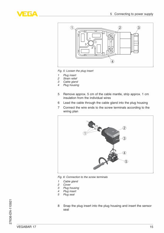
Fig. 5: Loosen the plug insert
1 Plug insert
2 Strain relief
3 Cable gland
4 Plug housing
5 Remove approx. 5 cm of the cable mantle, strip approx. 1 cminsulation from the individual wires
6 Lead the cable through the cable gland into the plug housing
7 Connect the wire ends to the screw terminals according to thewiring plan
1
5
2
3
4
Fig. 6: Connection to the screw terminals
1 Cable gland
2 Cover
3 Plug housing
4 Plug insert
5 Plug seal
8 Snap the plug insert into the plug housing and insert the sensorseal
VEGABAR 17 15
5 Connecting to power supply27636-EN-110921

Information:
Note the correct arrangement, see illustration
9 Tighten the screws on the strain relief and cable entry
10 Hook in the cover and push onto the plug connection, tightencover screw
11 Plug the plug insert with seal to VEGABAR 17 and tighten thescrew
The electrical connection is finished.
5.3 Wiring plan
1
2
3
+
-
1
Fig. 7: Wiring plan, angle plug connector according to ISO 4400, top view to
VEGABAR 17
1 Voltage supply and signal output
3
+
-
13
2
4
1
Fig. 8: Wiring plan, round plug connector M12 x 1, top view to VEGABAR 17
1 Voltage supply and signal output
Connection via confectioned cable with 4-pole socket M12 x 1
Angled plug connector
according to ISO 4400
Round plug connector
M12 x 1
16 VEGABAR 17
5 Connecting to power supply27636-EN-110921

Wire colour Connector
Brown 1
White 2
Blue 3
Black 4
1
2
3
Fig. 9: Wiring plan cable outlet
1 brown (+) power supply and signal output
2 green (-) power supply and signal output
3 blue = cable screen
321
–
+
–+
4 5
1
2
Fig. 10: Wiring plan, terminal housing
1 To power supply or the processing system
2 Control instrument (4 … 20 mA measurement)
Cable outlet
Terminal housing
VEGABAR 17 17
5 Connecting to power supply27636-EN-110921
6 Set up
6.1 Setup steps
After mounting and electrical connection, VEGABAR 17 is ready foroperation.
VEGABAR 17 delivers a current of 4 … 20 mA corresponding to theactual process pressure.
Further settings are not necessary.
6.2 Recalibration
On instruments with screwed ring or field housing, the zero and spancan be readjusted via the integrated potentiometers. An installationposition deviating from the reference installation position can thus becompensated for.
A shifting of zero shifts span also respectively.
Note:
The potentiometer for span should only be used if you have adequatecalibration equipment (at least 3 times more precise than the deviationof VEGABAR 17).
Recommended recalibration cycle: 1 year.
Proceed as follows:
1 Loosen the plug connector and screw the screwed ring inconnected status
2 Place the plug connector onto the instrument place and pull bothcarefully out of the instrument
Instruments with plug
connector or cable out-
let
18 VEGABAR 17
6 Set up27636-EN-110921

1
2
3
4
5
6
Fig. 11: Open the instrument
1 Plug connector
2 Plug seal
3 Screwed ring
4 Instrument plug
5 Plug seal
6 Housing
3 Set zero in unpressurized status, check 4 mA signal in the circuit
4 Set span with exact reference pressure
5 Check zero
VEGABAR 17 19
6 Set up27636-EN-110921

2 1
Fig. 12: Adjustment of zero and span
1 zero (Z)
2 span (S)
6 Assemble the instrument and connect it.
Proceed as follows:
1 Screw on the housing cover in connected status
4
5
Fig. 13: Adjustment of zero and span
1 zero (Z)
2 span (S)
2 Set zero in unpressurized status, check 4 mA signal in the circuit
3 Set a span with a sufficiently precise reference pressure
Instruments with termi-
nal housing
20 VEGABAR 17
6 Set up27636-EN-110921
4 Check zero
5 Screw the housing cover on
VEGABAR 17 21
6 Set up27636-EN-110921

7 Maintenance and fault rectification
7.1 Maintenance
If the instrument is used properly, no special maintenance is requiredin normal operation.
7.2 Remove interferences
The operator of the system is responsible for taking suitable measuresto rectify faults.
VEGABAR 17 offers maximum reliability. Nevertheless, faults canoccur during operation. These may be caused by the following, e.g.:
l Sensorl Processl Voltage supplyl Signal processing
The first measure to be taken is to check the output signal. In manycases, the causes can be determined this way and the faults rectified.
Should these measures not be successful, please call in urgent casesthe VEGA service hotline under the phone no. +49 1805 858550.
The hotline is available to you 7 days a week round-the-clock. Sincewe offer this service world-wide, the support is only available in theEnglish language. The service is free of charge, only the standardtelephone costs will be charged.
? No 4 … 20 mA signal
l Connection to voltage supply wrong
à Check connection according to chapter "Connection steps"
and if necessary, correct according to chapter "Wiring plan"
l No voltage supply
à Check cables for breaks; repair if necessary
l Operating voltage too low or load resistance too high
à Check, adapt if necessary
? Steady output signal with pressure change
l electronics module or measuring cell defective
à Exchange the instrument or send it in for repair
In Ex applications, the regulations for the wiring of intrinsically safecircuits must be observed.
Reaction when malfunc-
tions occur
Failure reasons
Fault rectification
24 hour service hotline
Checking the 4 … 20 mA
signal
22 VEGABAR 17
7 Maintenance and fault rectification27636-EN-110921
Depending on the failure reason and measures taken, the stepsdescribed in chapter "Set up" must be carried out again, if necessary.
7.3 Instrument repair
If a repair is necessary, please proceed as follows:
You can download a return form (23 KB) from our Internet homepagewww.vega.com under: "Downloads - Forms and certificates - Repair
form".
By doing this you help us carry out the repair quickly and withouthaving to call back for needed information.
l Print and fill out one form per instrumentl Clean the instrument and pack it damage-proofl Attach the completed form and, if need be, also a safety data
sheet outside on the packagingl Please ask the agency serving you for the address of your return
shipment. You can find the respective agency on our websitewww.vega.com under: "Company - VEGA worldwide"
Reaction after fault rec-
tification
VEGABAR 17 23
7 Maintenance and fault rectification27636-EN-110921

8 Dismounting
8.1 Dismounting steps
Warning:
Before dismounting, be aware of dangerous process conditions suchas e.g. pressure in the vessel, high temperatures, corrosive or toxicproducts etc.
Take note of chapters "Mounting" and "Connecting to power supply"
and carry out the listed steps in reverse order.
8.2 Disposal
The instrument consists of materials which can be recycled byspecialised recycling companies. We use recyclable materials andhave designed the electronics to be easily separable.
WEEE directive 2002/96/EG
This instrument is not subject to the WEEE directive 2002/96/EG andthe respective national laws. Pass the instrument directly on to aspecialised recycling company and do not use the municipal collectingpoints. These may be used only for privately used products accordingto the WEEE directive.
Correct disposal avoids negative effects on humans and the environ-ment and ensures recycling of useful raw materials.
Materials: see chapter "Technical data"
If you have no way to dispose of the old instrument properly, pleasecontact us concerning return and disposal.
24 VEGABAR 17
8 Dismounting27636-EN-110921

9 Supplement
9.1 Technical data
General data
Parameter, pressure Gauge pressure, absolute pressure, vacuum
Measuring principle Piezoresistive/Thin film DMS
Communication interface None
Materials and weights
Materials, wetted parts- Process fitting 316Ti
- Diaphragm 316Ti
- Diaphragm with front flush version 316Ti, Hastelloy C4
- Seal, O-ring FKM, EPDM, NBR
Materials, non-wetted parts- Internal transmission liquid Synthetic oil, Halocarbon oil2)3)
- Housing 316Ti
- Terminal housing 316Ti
- Ground terminal 316Ti
- Plug PA
- Cable gland PA, 316Ti
- Plug seal Silicone
- Connection cable PUR
Available cable length max. 40 m
Weight approx.- Version with plug connector, cable outlet 0.2 kg (0.441 lbs)
- Version with terminal housing 0.35 kg (0.772 lbs)
Output variable
Output signal 4 … 20 mA
Zero and span adjustable via potentiometer ±5 %
Dead time ≤ 1 ms
Step response time (10 … 90 %)
- Standard version ≤ 1 ms
- Version for medium temperature < -30 °C
(-22 °F)
≤ 10 ms
2) Synthetic oil: For measuring ranges up to 16 bar, FDA listed for the foodprocessing industry. For measuring ranges up to 25 bar not available.
3) Halocarbon oil: With version oil and greasefree, not with vacuummeasuringranges, not with absolute measuring ranges < 1 barabs.
VEGABAR 17 25
9 Supplement27636-EN-110921

- Version for measuring ranges > 25 bar ≤ 10 ms
- Version with front-flush diaphragm ≤ 10 ms
Reference conditions and actuating variables (similar to DIN EN 60770-1)
Reference conditions according to DIN EN 61298-1
- Temperature +15 … +25 °C (+59 … +77 °F)
- Relative humidity 45 … 75 %
- Air pressure 860 … 1060 mbar/86 … 106 kPa (12.5 … 15.4 psi)
Determination of characteristics Limit point adjustment according to IEC 61298-2
Reference installation position upright, diaphragm points downward
Influence of the installation position depending on the chemical seal version
Input variable
The availability of the respective measuring range depends on the corresponding process fitting.
The overload specifications are only an overview and refer to the measuring cell. Limitations bymaterial and process fitting version are possible. The specifications on the type label areapplicable.
Nominal range Overload capacity, max.
pressure
Overload capacity, min.
pressure
Gauge pressure
-0.1 … 0 bar/-10 … 0 kPa 1 bar/100 kPa -1 bar/-100 kPa
-0.16 … 0 bar/-16 … 0 kPa 1.5 bar/150 kPa -1 bar/-100 kPa
-0.25 … 0 bar/-25 … 0 kPa 2 bar/200 kPa -1 bar/-100 kPa
-0.4 … 0 bar/-40 … 0 kPa 2 bar/200 kPa -1 bar/-100 kPa
-0.6 … 0 bar/-60 … 0 kPa 4 bar/400 kPa -1 bar/-100 kPa
-1 … 0 bar/-100 … 0 kPa 5 bar/500 kPa -1 bar/-100 kPa
-1 … 3 bar/-100 … 300 kPa 10 bar/1000 kPa -1 bar/-100 kPa
0 … 0.1 bar/0 … 10 kPa 1 bar/100 kPa -1 bar/-100 kPa
0 … 0.16 bar/0 … 16 kPa 1.5 bar/150 kPa -1 bar/-100 kPa
0 … 0.25 bar/0 … 25 kPa 2 bar/200 kPa -1 bar/-100 kPa
0 … 0.4 bar/0 … 40 kPa 2 bar/200 kPa -1 bar/-100 kPa
0 … 0.6 bar/0 … 60 kPa 4 bar/400 kPa -1 bar/-100 kPa
0 … 1 bar/0 … 100 kPa 5 bar/500 kPa -1 bar/-100 kPa
0 … 1.6 bar/0 … 160 kPa 10 bar/1000 kPa -1 bar/-100 kPa
0 … 2.5 bar/0 … 250 kPa 10 bar/1000 kPa -1 bar/-100 kPa
0 … 4 bar/0 … 40 kPa 17 bar/1700 kPa -1 bar/-100 kPa
0 … 6 bar/0 … 600 kPa 35 bar/3500 kPa -1 bar/-100 kPa
0 … 10 bar/0 … 1000 kPa 35 bar/3500 kPa -1 bar/-100 kPa
0 … 16 bar/0 … 1600 kPa 80 bar/8000 kPa -1 bar/-100 kPa
0 … 25 bar/0 … 2500 kPa 50 bar/5000 kPa -1 bar/-100 kPa
26 VEGABAR 17
9 Supplement27636-EN-110921

Nominal range Overload capacity, max.
pressure
Overload capacity, min.
pressure
0 … 40 bar/0 … 4000 kPa 80 bar/8000 kPa -1 bar/-100 kPa
0 … 60 bar/0 … 6000 kPa 120 bar/12 MPa -1 bar/-100 kPa
0 … 100 bar/0 … 10 MPa 200 bar/20 MPa -1 bar/-100 kPa
0 … 160 bar/0 … 16 MPa 320 bar/32 MPa -1 bar/-100 kPa
0 … 250 bar/0 … 25 MPa 500 bar/50 MPa -1 bar/-100 kPa
0 … 400 bar/0 … 40 MPa 800 bar/80 MPa -1 bar/-100 kPa
0 … 600 bar/0 … 60 MPa 1200 bar/120 MPa -1 bar/-100 kPa
0 … 1000 bar/0 … 100 MPa 1500 bar/150 MPa -1 bar/-100 kPa
Absolute pressure
0 … 0.25 bar/0 … 25 kPa 2 bar/200 kPa
0 … 0.4 bar/0 … 40 kPa 2 bar/200 kPa
0 … 0.6 bar/0 … 60 kPa 4 bar/400 kPa
0 … 1 bar/0 … 100 kPa 5 bar/500 kPa
0 … 1.6 bar/0 … 160 kPa 10 bar/1000 kPa
0 … 2.5 bar/0 … 250 kPa 10 bar/1000 kPa
0 … 4 bar/0 … 400 kPa 17 bar/1700 kPa
0 … 6 bar/0 … 600 kPa 35 bar/3500 kPa
0 … 10 bar/0 … 1000 kPa 35 bar/3500 kPa
0 … 16 bar/0 … 1600 kPa 80 bar/8 MPa
Deviation4)
Deviation ≤ 0.5 %
Influence of the product or ambient temperature5)
The following specifications apply to values within the compensated temperature range, i.e.0 … 80 °C (176 °F), reference temperature 20 °C (68 °F).
Average temperature coefficient of the zero signal- Standard < 0.2 %/10 K
- Meas. ranges 0 … 0.1 and 0 … 0.16 bar < 0.4 %/10 K
Average temperature coefficient of the span < 0.2 %/10 K
The following specifications are valid for values not within the compensated temperature range.
Average temperature coefficient of the zero signal- Standard typ. < 0.2 %/10 K
- Meas. ranges 0 … 0.1 and 0 … 0.16 bar typ. < 0.4 %/10 K
Average temperature coefficient of the span typ. < 0.2 %/10 K
4) Relating to the adjusted span, incl. non-linearity, hysteresis and non-repro-ducibility.
5) Relating to the set span, incl. hysteresis and repeatability.
VEGABAR 17 27
9 Supplement27636-EN-110921

Long-term stability (similar to DIN 16086, DINV 19259-1 and IEC 60770-1)
Long-term drift of the zero signal6) < 0.2 %/year
Ambient conditions
Ambient temperature (note temperature derating!)- Cable outlet -20 … +80 °C (-4 … +176 °F)
- Round plug connector M12 x 1 -25 … +80 °C (-13 … +176 °F)
- Angled plug connector according toISO 4400
-40 … +80 °C (-40 … +176 °F)
- Terminal housing -50 … +80 °C (-58 … +176 °F)
1
2
55°C(131°F)
80°C(176°F)
130°C(266°F)
150°C(302°F)
Fig. 14: Temperature derating VEGABAR 17
1 Process temperature
2 Ambient temperature
Storage and transport temperature -30 … +105 °C (-22 … +221 °F)
Process conditions
Product temperature- Standard -30 … +100 °C (-22 … +212 °F)
- additional -40 … +125 °C (-40 … +257 °F)
- with cooling element -20 … +150 °C (-4 … +302 °F)
Shock resistance- Version with terminal housing 600 g according to IEC 60068-2-27 (mechanical
shock)
- Version with plug connector or cableoutlet
1000 g according to IEC 60068-2-27 (mechanicalshock)
Vibration resistance- Version with terminal housing 10 g according to IEC 60068-2-6 (vibration at
resonance)
6) Under reference conditions, relating to the adjusted span.
28 VEGABAR 17
9 Supplement27636-EN-110921

- Version with plug connector or cableoutlet
20 g according to IEC 60068-2-6 (vibration atresonance)
Electromechanical data
Angled plug connector- Version 4-pole according to ISO 4400
- Outer cable diameter 6 … 8 mm
Circular plug connector- Version 4-pole M12 x 1
Cable outlet- Diameter 6.8 mm
Terminal housing- Cable entry for cable outer diameter 6 … 8 mm
- Spring-loaded terminals for wire cross-section up to
2.5 mm² (AWG 14)
Voltage supply
Operating voltage- Version with plug or cable outlet 10 … 30 V DC
- Version with terminal housing 11 … 30 V DC
Load- Version with cable outlet RA ≤ (U-10V)/0,02 A- (length of the cable version in
m x 0.14 Ω)
- Version with plug see diagram
- Version with terminal housing see diagram
950
750
500
250
10 161412 18 20 22 24 26 28 30 32 3634
Ω
V
2
1
3
Fig. 15: Voltage diagram VEGABAR 17 with plug
1 Voltage limit
2 Operating voltage
3 Max. load
VEGABAR 17 29
9 Supplement27636-EN-110921

950
750
500
250
11 161412 18 20 22 24 26 28 30 32 3634
Ω
V
2
1
3
Fig. 16: Voltage diagram VEGABAR 17 with terminal housing
1 Voltage limit
2 Operating voltage
3 Max. load
Electrical protective measures
Protection rating7)
- with angled plug connector IP 65
- with round plug connection IP 65
- with cable outlet IP 67, IP 68, 0.5 bar
- with terminal housing IP 67
Voltage resistance Insulation according to EN 50020, 6.4, 12
Interference resistance- HF 10 V/m
- Burst 2 kV
Other protective measures Interpolation and shortcircuit protection
Approvals
Instruments with approvals can have different technical data depending on the version.
That's why the associated approval documents have to be noted with these instruments. They arepart of the delivery or can be downloaded under www.vega.com via "VEGA Tools" and "serial
number search" as well as via "Downloads" and "Approvals".
7) According to EN 60529/IEC 529.
30 VEGABAR 17
9 Supplement27636-EN-110921

9.2 Dimensions
VEGABAR 17 - standard housing
SW27
G1/2B G1B
G1/4B
G1/2B
1/4NPT 1/2NPT
G1B
20
,5m
m
(13/ 1
6")
1
0m
m
(25/ 6
4")
~1
16
mm
(4
9/ 1
6")
~1
16
mm
(4
9/ 1
6")
~1
23
mm
(4
27/ 3
2")
~1
26
mm
(4
61/ 6
4")
ø 27mm
(1 1/16")
SW41
G1B
28
mm
(1 7
/ 64")
~1
35
mm
(5
5/ 1
6")
ø 30mm
(1 3/16")
13
mm
(33/ 6
4")
2m
m
(5/ 6
4")
3m
m
(1/ 8
")
3m
m
(1/ 8
")
3m
m 2
0m
m
(25/ 3
2")
27
,5m
m
(1 5
/ 64")
13
,5m
m
(17/ 3
2")
12
mm
(15/ 3
2")
~1
23
mm
(4
27/ 3
2")
19
mm
(3/ 4
")
13
mm
(33/ 6
4")
2m
m
ø 5mm
(13/64")
ø 6mm
(15/64")
ø 9,5mm
(3/8")
ø 17,5mm
(11/16")
G1/2B
G¼B
~1
23
mm
(4
27/ 3
2")
20
mm
(25/ 3
2")
ø 17,5mm
(11/16")
~48mm
(1 57/64")
ø 30mm
(1 3/16")
G1/2B
20
,5m
m
(13/ 1
6")
10
mm
(25/ 6
4")
~1
26
mm
(4
61/ 6
4")
ø 18mm
(45/64")
~ 1
7,5
~ 1
7,5
1 2 3 4 5
GBX
NBX NDX
84L/84B
GDX
TBX 851/85L/85B 861/86L/86B
Fig. 17: VEGABAR 17 - dimensions with * in brackets apply to Ex versions, GDX = G½ B manometer connection,
TBX = G½ B, innerG¼ B, 84L/84B = G1 B front-flush max. 25 bar, 851/85L/85B = G1 B front-flush withO-ring up to
1.6 bar, 861/86L/86B = G½ B front-flush with O-ting > 1.6 bar, GBX = G¼ B manometer connection, NBX = ¼ NPT
thread, NDX = ½ NPT thread
1 Cooling element G½ B
2 Cooling element G1 B
3 Plug according to ISO 4400
4 Cable outlet
5 M12 x 1 plug
VEGABAR 17 31
9 Supplement27636-EN-110921

VEGABAR 17 - terminal housing
SW27
G1/2B G1B
G1/4B
G1/2B
1/4NPT 1/2NPT
G1BG1/2B
20
,5 m
m
(13/ 1
6")
20
,5 m
m
(13/ 1
6")
10
mm
(25/ 6
4")
10
mm
(25/ 6
4")
~1
28
mm
(5
3/ 6
4")
~1
28
mm
(5
3/ 6
4")
~1
35
mm
(5
5/ 1
6")
~1
34
mm
(5
9/ 3
2")
13
8 m
m (
5 7
/ 16")
13
8 m
m (
5 7
/ 16")
SW41
G1B
28
mm
(1 7
/ 64")
14
2 m
m (
5 1
9/ 3
2")
ø 27 mm
(1 1/16")
ø 30 mm
(1 3/16")
max. 90mm (3 35/64")
ø 61 mm
(2 13/32 ")
13
mm
(33/ 6
4")
2 m
m
(5/ 6
4")
3 m
m
(1/ 8
")3
mm
20
mm
(25/ 3
2")
19
mm
(3/ 4
")
13
mm
(33/ 6
4")
2 m
m
ø 5 mm
(13/64")
ø 6 mm
(15/64")
ø 9,5 mm
(3/8")
ø 17,5 mm
(11/16")
~1
35
mm
(5
5/ 1
6")
3 m
m
(1/ 8
")
20
mm
(25/ 3
2")
ø 17,5 mm
(11/16")
ø 30 mm
(1 3/16")
ø 18 mm
(45/64")
G1/2B
G¼B
~ 1
7,5
~ 1
7,5
1 2
GDX
GBX
NBX NDX
861/86L/86B 851/85L/85B
84L/84B
TBX
Fig. 18: VEGABAR 17 - terminal housing, GDX = G½ B manometer connection, TBX = G½ B, inner G¼ B, 84L/84B
= G1 B front-flush max. 25 bar, 851/85L/85B = G1 B front-flush withO-ring up to 1.6 bar, 861/86L/86B = G½ B front-
flush with O-ring > 1.6 bar, GBX = G¼ B manometer connection, NBX = ¼ NPT thread, NDX = ½ NPT thread
1 Cooling element G½ B
2 Cooling element G1 B
32 VEGABAR 17
9 Supplement27636-EN-110921
VEGABAR 17 33
9 Supplement27636-EN-110921

34 VEGABAR 17
9 Supplement27636-EN-110921

VEGABAR 17 35
9 Supplement27636-EN-110921

VEGA Grieshaber KGAm Hohenstein 11377761 SchiltachGermanyPhone +49 7836 50-0Fax +49 7836 50-201E-mail: [email protected]
Printing date:
ISO 9001
All statements concerning scope of delivery, application,practical use and operating conditions of the sensors andprocessing systems correspond to the information avail-
able at the time of printing.
© VEGA Grieshaber KG, Schiltach/Germany 2011
Subject to change without prior notice 27636-EN-110921