operating instructions ultromat atr - prominent · ultromat® atr flow system operating...
TRANSCRIPT
Ultromat® ATRFlow System
Operating instructions
Part no. 986365 BA UL 013 05/09 GB
Please carefully read these operating instructions before use! · Do not discard!The operator shall be liable for any damage caused by installation or operating errors!
Technical changes reserved.

986365, 1, en_GB
© 2009
ProMinent Dosiertechnik GmbHIm Schuhmachergewann 5-1169123 HeidelbergTelephone: +49 6221 842-0Fax: +49 6221 842-419email: [email protected]: www.prominent.com
2

Table of contents1 Product Identification - Ultromat®.......................................... 5
1.1 Product Identification - Ultromat®.................................. 51.2 Front View of Ultromat® ATR........................................ 61.3 Plan View of Ultromat® ATR......................................... 71.4 About This Product....................................................... 8
2 Safety Chapter...................................................................... 92.1 Explanation of the safety information............................ 92.2 Users' Qualifications................................................... 102.3 Information in the Event of an Emergency.................. 112.4 Description and Testing of Safety Equipment............. 122.5 Ultromat® Safety Information...................................... 132.6 Sound Pressure Level................................................ 14
3 Transport and Storage of the System................................. 153.1 Transport and Storage of the System......................... 15
4 Information on the System.................................................. 164.1 Application.................................................................. 164.2 Design......................................................................... 164.3 System Dimensions.................................................... 16
5 Design and Function........................................................... 185.1 Description of the Component Assemblies................. 185.1.1 Three-Chamber Reservoir....................................... 185.1.2 Dry Material Feeder................................................. 185.1.3 Agitators................................................................... 185.1.4 Switching Cabinet.................................................... 185.1.5 Power Socket for the Connection of a Conveyor
Unit.......................................................................... 185.1.6 Remote Operation................................................... 195.1.7 Crane Lifting Lugs.................................................... 195.1.8 Analysis of Insufficient Water for the Redilution
Unit.......................................................................... 195.2 Operating Modes........................................................ 195.2.1 Automatic Mode....................................................... 195.2.2 Calibration Mode...................................................... 195.3 Ultromat® Options....................................................... 195.3.1 Agitator for Reservoir 3 (Agitator 3)......................... 205.3.2 Overflow Protection for Reservoir 3......................... 205.3.3 Vibrator ................................................................... 205.4 Ultromat® Accessories................................................ 205.4.1 Powder Storage Container...................................... 205.4.2 Powder Storage Container with Sack Tilting
Device...................................................................... 205.4.3 Redilution Unit......................................................... 205.4.4 50 l, 75 l and 100 l Add-On Hopper (with / without
Adapter Connection for Powder Conveyor Unit)...... 205.4.5 Powder Conveyor Unit for Automatic Refilling......... 21
Table of contents
3
6 Assembly and Installation................................................... 226.1 Assembly.................................................................... 226.2 Hydraulic Installation................................................... 226.3 Electrical Installation................................................... 236.3.1 Mains Power Connection......................................... 23
7 Controller............................................................................ 247.1 Design and Function................................................... 247.1.1 Display and Operating Elements............................. 247.1.2 Calibration................................................................ 247.1.3 Mode: Prepare "0"................................................... 257.1.4 Mode: Prepare "Auto".............................................. 257.1.5 Mode: Prepare "Remote Control Mode".................. 257.1.6 Setting Control Parameters..................................... 267.1.7 Fault Messages....................................................... 28
8 Commissioning................................................................... 318.1 Assembly, Preparatory Work...................................... 318.2 Settings for Commissioning........................................ 318.2.1 Water Supply Setting............................................... 328.2.2 Calibrating the Dry Material Feeder......................... 328.2.3 Adjusting the Capacitive Sensor.............................. 338.3 Setting the Altivar 11 Frequency Inverter................... 348.3.1 Operating Element Functions.................................. 348.3.2 Parameter Settings.................................................. 348.4 Operation of the System............................................. 37
9 Operation of the System..................................................... 389.1 Normal Mode.............................................................. 389.1.1 Prerequisites for Correct and Proper Operation...... 389.1.2 Feeding the Storage Hopper with Powdered Pol‐
ymer......................................................................... 389.2 Behaviour When Switching on Mains Power and in
the Event of Mains Power Failure............................... 389.3 Decommissioning....................................................... 399.4 Disposal...................................................................... 39
10 Incorrect Operation of the System...................................... 40
11 Troubleshooting.................................................................. 41
12 Maintenance....................................................................... 4212.1 Inspecting the Dry Material Feeder........................... 4212.2 Cleaning the Screen Insert in the Pressure
Reducer.................................................................... 4212.3 Dismantling the Cover of an Inspection Opening..... 4212.4 Cleaning the Surface of the Ultromat® ..................... 42
13 Spare Parts and Accessories.............................................. 4313.1 Spare Parts............................................................... 4313.2 Accessories.............................................................. 43
14 Declaration of Conformity................................................... 44
15 Commissioning Report........................................................ 45
Table of contents
4

1 Product Identification - Ultromat®
1.1 Product Identification - Ultromat®
Ultromat® ATR 1033810 1033811 1033812
Type ATR 400 ATR 1000 ATR 2000
Reservoir contents 400 l 1000 l 2000 l
Product Identification - Ultromat®
5
1.2 Front View of Ultromat® ATR
12
34
5 67
8
9
10111213
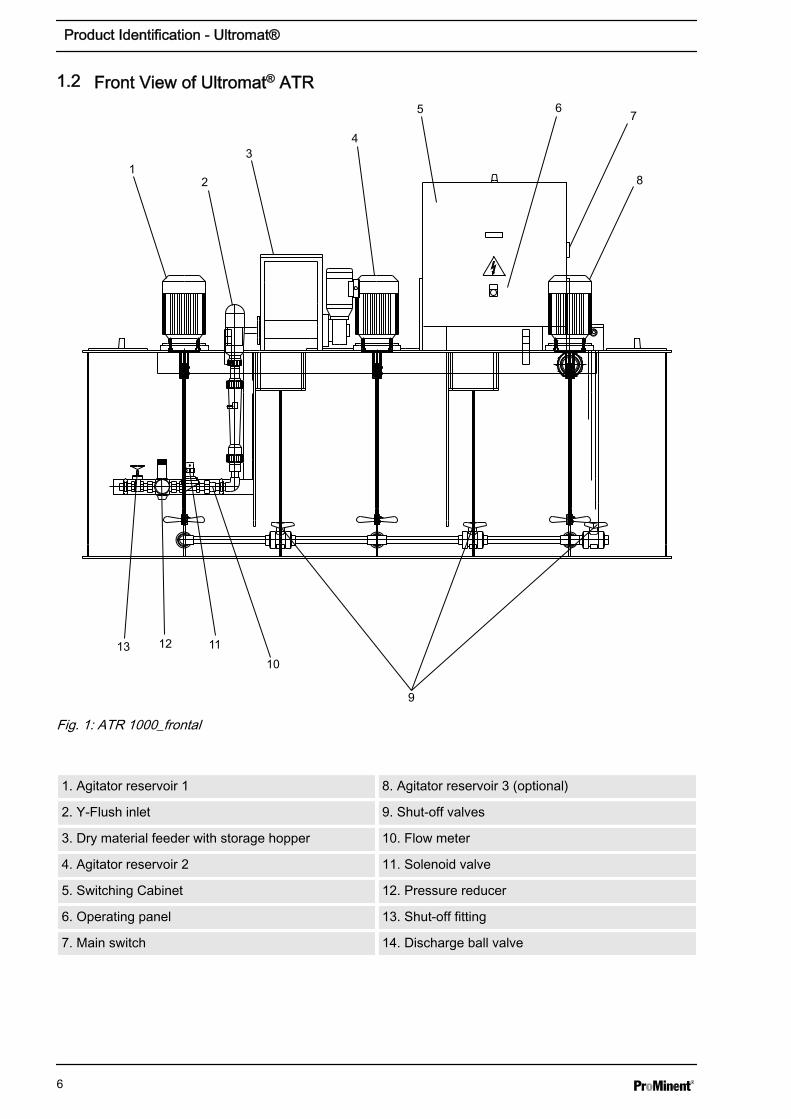
Fig. 1: ATR 1000_frontal
1. Agitator reservoir 1 8. Agitator reservoir 3 (optional)
2. Y-Flush inlet 9. Shut-off valves
3. Dry material feeder with storage hopper 10. Flow meter
4. Agitator reservoir 2 11. Solenoid valve
5. Switching Cabinet 12. Pressure reducer
6. Operating panel 13. Shut-off fitting
7. Main switch 14. Discharge ball valve
Product Identification - Ultromat®
6
1.3 Plan View of Ultromat® ATR
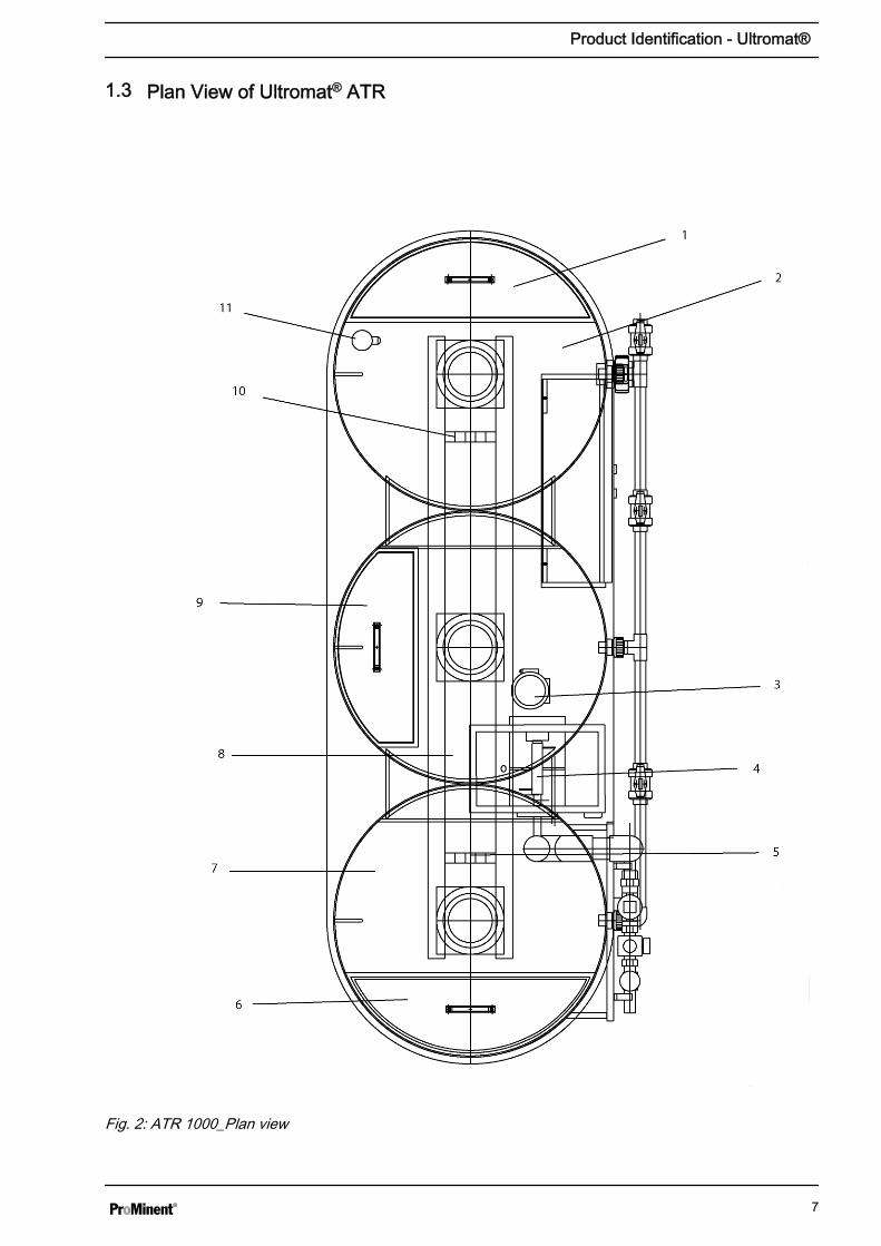
Fig. 2: ATR 1000_Plan view
Product Identification - Ultromat®
7
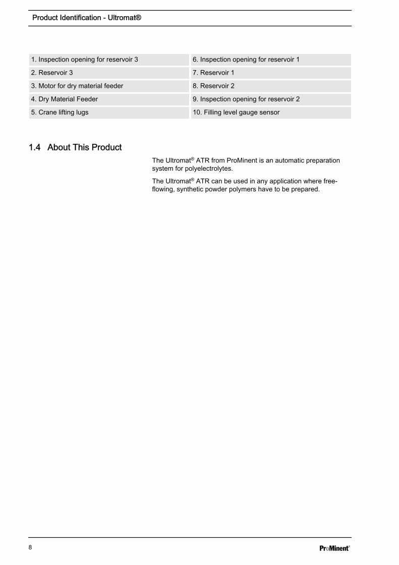
1. Inspection opening for reservoir 3 6. Inspection opening for reservoir 1
2. Reservoir 3 7. Reservoir 1
3. Motor for dry material feeder 8. Reservoir 2
4. Dry Material Feeder 9. Inspection opening for reservoir 2
5. Crane lifting lugs 10. Filling level gauge sensor
1.4 About This ProductThe Ultromat® ATR from ProMinent is an automatic preparationsystem for polyelectrolytes.
The Ultromat® ATR can be used in any application where free-flowing, synthetic powder polymers have to be prepared.
Product Identification - Ultromat®
8
2 Safety Chapter
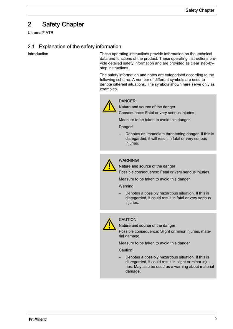
2.1 Explanation of the safety informationThese operating instructions provide information on the technicaldata and functions of the product. These operating instructions pro‐vide detailed safety information and are provided as clear step-by-step instructions.
The safety information and notes are categorised according to thefollowing scheme. A number of different symbols are used todenote different situations. The symbols shown here serve only asexamples.
DANGER!Nature and source of the dangerConsequence: Fatal or very serious injuries.
Measure to be taken to avoid this danger
Danger!
– Denotes an immediate threatening danger. If this isdisregarded, it will result in fatal or very seriousinjuries.
WARNING!Nature and source of the dangerPossible consequence: Fatal or very serious injuries.
Measure to be taken to avoid this danger
Warning!
– Denotes a possibly hazardous situation. If this isdisregarded, it could result in fatal or very seriousinjuries.
CAUTION!Nature and source of the dangerPossible consequence: Slight or minor injuries, mate‐rial damage.
Measure to be taken to avoid this danger
Caution!
– Denotes a possibly hazardous situation. If this isdisregarded, it could result in slight or minor inju‐ries. May also be used as a warning about materialdamage.
Ultromat® ATR
Introduction
Safety Chapter
9

NOTICE!Nature and source of the dangerDamage to the product or its surroundings
Measure to be taken to avoid this danger
Note!
– Denotes a possibly damaging situation. If this isdisregarded, the product or an object in its vicinitycould be damaged.
Type of informationHints on use and additional informationSource of the information, additional measuresInformation!– Denotes hints on use and other useful information.
It does not indicate a hazardous or damaging sit‐uation.
2.2 Users' Qualifications
WARNING!Danger of injury with inadequately qualified personnel!If inadequately qualified personnel work on the unit orloiter in the hazard zone of the unit, this could result indangers that could cause serious injuries and materialdamage.
– All work on the unit should therefore only be con‐ducted by qualified personnel.
– Unqualified personnel should be kept away fromthe hazard zone.
Activity Training
Assembly / Installation trained qualified personnel
Commissioning technical experts
Operation instructed personnel
Maintenance / Repair Customer service department
Decommissioning / Disposal technical experts
Troubleshooting instructed personnel
Explanation of the terms:
Safety Chapter
10

n A technical expert is deemed to be a person who is able toassess the tasks assigned to him and recognise possible haz‐ards based on his/her technical training and experience, aswell as knowledge of pertinent regulations.Note: A technical qualification is typically proven by therequired completion of a technical training course. The assess‐ment of a person's technical training can also be based on sev‐eral years of work in the relevant field.
n A qualified employee is deemed to be a person who is able toassess the tasks assigned to him and recognise possible haz‐ards based on his/her technical training, knowledge and experi‐ence, as well as knowledge of pertinent regulations.Note: The assessment of a person's technical training can alsobe based on several years of work in the relevant field.
n An instructed person is deemed to be a person who has beeninstructed and, if required, trained in the tasks assigned to him/her and possible dangers that could result from improperbehaviour, as well as having been instructed in the requiredprotective equipment and protective measures.
n Customer service department refers to service technicians,who have received proven training and have been authorisedby ProMinent to work on the system.
Note for the system operatorThe pertinent accident prevention regulations, as wellas all other generally acknowledged safety regulations,must be adhered to!
2.3 Information in the Event of an Emergency
WARNING!Information in the Event of an EmergencyPossible consequence: Fatal or very serious injuries
Switch off the system with the red-yellow main switch.
Red-yellow main switch is located on the right-handside of the switching cabinet!
Safety Chapter
11
2.4 Description and Testing of Safety Equipment
3 4
3
2
1
3
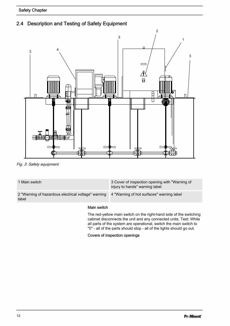
Fig. 3: Safety equipment
1 Main switch 3 Cover of inspection opening with "Warning ofinjury to hands" warning label
2 "Warning of hazardous electrical voltage" warninglabel
4 "Warning of hot surfaces" warning label
Main switch
The red-yellow main switch on the right-hand side of the switchingcabinet disconnects the unit and any connected units. Test: Whileall parts of the system are operational, switch the main switch to"0" - all of the parts should stop - all of the lights should go out.
Covers of inspection openings
Safety Chapter
12

The screw covers of the inspection openings prevent personsinjuring themselves on the rotating propellers of the agitators. Test:Check that the covers of the inspection openings are being usedand are secured with screws.
Warning labels
Warning of hazardous electrical voltage
Warning of injury to hands
Warning of hot surfaces
Test: Check whether the labels are still affixed and legible.
2.5 Ultromat® Safety Information
WARNING!Qualification of personnelDanger due to incorrect operation of the system
The operating personnel must be instructed by aProMinent service technician" (When the system is firstoperated)
The operating instructions must be available by thesystem!
WARNING!Danger of electric shock!Possible consequence: Fatal or very serious injuries
The control cabinet must always be closed during ope‐ration.
The mains switch must be set to "0" and securedagainst restart before any installation or maintenancework can begin.
Safety Chapter
13

CAUTION!Propellers are rotating in the reservoirs!Slight or minor injuries.
Switch off the system and only then remove thescrewed cover of an inspection opening!
CAUTION!A screw conveyor and a loosening wheel are locatedunder the safety guard of the dry material feeder.Slight or minor injuries. Material damage.
Do not reach into the dry material feeder.
CAUTION!Hot surface!Incorrectly set heating on the metering pipe maybecome hot!
Ensure that the metering pipe heating is correctly set!
2.6 Sound Pressure LevelThe sound pressure level is < 70 dB (A) for powdered polymer,according to EN ISO 11202:1997 (Acoustics - Noise emission frommachinery and equipment)
Safety Chapter
14

3 Transport and Storage of the System3.1 Transport and Storage of the System
CAUTION!Fractures in plastic material may result from incorrectloading– Only move the Ultromat® system when empty– The reservoir wall may not be subjected to point
loads– Avoid heavy vibrations and impact loads– Only move the system with suitable hoisting and
lifting equipment– When using forklift trucks, use long forks, which
extend across the entire depth of the three-chamber reservoir
– If a crane is used, fit the transport belts such thatshear stress is avoided, even if lifting lugs exist
– The support must be able to carry the weight of thesystem
Ambient conditions for storage and transport
Permissible ambient temperature: -5 °C to +50 °C
Humidity: none
Other: No dust, no direct sunlight
Transport and Storage of the System
15

4 Information on the System4.1 Application
The Ultromat® ATR from ProMinent is an automatic preparationsystem for polyelectrolytes.
The Ultromat® ATR can be used in any application where free-flowing, synthetic powder polymers have to be prepared.
4.2 DesignAlmost all commercially available polymers can be used.
Concentrations of 0.05 to 0.5 % can be set. The viscosity of thepolymer solution produced may not exceed 1500 mPas. Pleaserefer to the application data sheets of the polymer suppliers forinformation about the viscosity of the different polymer solutions.
Adjust the flow rate of the preparation water to make full use of thepreparation chamber. Concentrations of greater than 0.5 % canreduce the capacity of the preparation performance.
The maturing time available for the production of a polymer solu‐tion depends on the discharge quantity and the volumetric capacityof the Ultromat® and is approximately 60 minutes at a maximumdischarge rate.
4.3 System Dimensions
Ultromat® ATR 1033810 1033811 1033812
Type ATR 400 ATR 1000 ATR 2000
Reservoir contents 400 l 1000 l 2000 l
Solution concentration 0,05 - 0,5 % 0,05 - 0,5 % 0,05 - 0,5 %
Dimensions LxWxH(mm)
2164x883x1216 2464x983x1566 2950x1157x1716
Weight when empty 130 kg 150 kg 180 kg
Total weight 530 kg 1150 kg 2180 kg
Overflow connection DN 40 DN 50 DN 50
Discharge connection DN 25 DN 25 DN 32
Water supply for redilu‐tion
1" 1" 1"
Recommended watersupply rate
1,500 l/h 1,500 l/h 3000 l/h
Electrical rating 1.5 kW 2.6 kW 3.2 kW
Ultromat® ATR
Information on the System
16

Ultromat® ATR 1033810 1033811 1033812
External fuse 20 A 20 A 20 A
Controller Siemens logo Siemens logo Siemens logo
Agitators: 1031374 1031375 1031376
Agitator output 0.18 kW 0.55 kW 0.75 kW
Agitator speed (50 Hz) 750 rpm 750 rpm 750 rpm
Propellers 1 1 1
Propeller diameter 120 mm 170 mm 200 mm
Length of agitator shaft 430 mm 720 mm 790 mm
Voltage 400 VAC 400 VAC 400 VAC
Nominal current 0.84 A 2.3 A 3.1 A
Weight 12 kg 21 kg 26 kg
Powder feeder: 1020800 1020800 1020800
Type TGD 18.13 TGD 18.13 TGD 18.13
Maximum meteringpower (100 Hz)
18 kg/h 18 kg/h 18 kg/h
Drive unit power 0.18 kW 0.18 kW 0.18 kW
Voltage 230 VAC 230 VAC 230 VAC
Nominal current 1.10 A 1.10 A 1.10 A
Speed of conveyingscrew at 100 Hz
200 rpm 200 rpm 200 rpm
Weight 15 kg 15 kg 15 kg
Information on the System
17

5 Design and Function5.1 Description of the Component Assemblies
5.1.1 Three-Chamber ReservoirThe PP reservoir is divided into three separate chambers, so that asufficient maturing time for the polymer solution can be ensured.The division of the reservoir largely prevents the matured andfreshly prepared solution from mixing and ensures continuous dis‐charge.
The fill level of reservoir 3 is monitored by a fill level gauge. Thesystem is equipped with a minimum and maximum contact to startor stop the automatic preparation process, as well as an emptycontact to prevent it from running dry.
5.1.2 Dry Material FeederPlease refer to the separate operating instructions entitled "DryMaterial Feeder" for detailed information about the design andfunction of this equipment. The heating for the metering pipe andthe minimum fill level sensor for the dry material hopper are fittedas standard. The dry material feeder is activated by a frequencyinverter to meter the powdered polymer into the preparation water.
A loosening wheel is fitted directly above the feeder screw for thecontinuous discharge of the powdered polymer. A metering pipeheating system also removes any moisture that has penetrated theunit and thus prevents any caking of the powdered polymer.
5.1.3 AgitatorsThe Ultromat® ATR is fitted as standard with two electrical agita‐tors. A third agitator for reservoir 3 can be supplied as an option.The agitators ensure that the solution is gently agitated in the res‐ervoir chambers. The agitators can start up suddenly as soon asthey are supplied with mains power!
5.1.4 Switching CabinetAll of the electrical control and command devices required tooperate the system are accommodated in the switching cabinet.
5.1.5 Power Socket for the Connection of a Conveyor UnitThe Ultromat® is fitted with a power socket to connect a conveyorunit. The power socket is fitted to the side of the switching cabinetand is secured electrically by a circuit breaker.
Design and Function
18
5.1.6 Remote OperationThis function enables the system to be remote controlled ifrequired. The Ultromat® can be switched to Automatic or "0" modevia an external switch.
5.1.7 Crane Lifting LugsA suitable hoisting device can be attached to the two crane liftinglugs.
5.1.8 Analysis of Insufficient Water for the Redilution UnitThe redilution unit is used to redilute the prepared polymer solu‐tion. To do so, a transfer pump (the transfer pump is not includedas standard with the Ultromat® ATR ) conveys the polymer solutionfrom reservoir 3 of the Ultromat® to the redilution unit.
The dilution water is fed into the redilution unit via a solenoid valve.A flow meter float with a minimum contact monitors the dilutionwater. The minimum contact of the rotameter is monitored by the"Analyse Redilution Unit" function. Should the minimum contactdisplay insufficient water, the Ultromat® goes into fault mode andthe transfer pump stops the polymer solution.
The Ultromat® switches the transfer pump off when the level of thepolymer solution in reservoir 3 drops below the dry run level.
5.2 Operating Modes5.2.1 Automatic Mode
Once it has reached the minimum level in reservoir 3, theUltromat® starts up the preparation process. The solenoid valve onthe water supply opens and the dry material feeder begins to feedin the powdered polymer once the time delay has elapsed. Oncethe maximum level has been reached, the control unit firstlyswitches off the dry material feeder and closes the solenoid valveon the water supply once the run-on time has been completed.
5.2.2 Calibration ModeWhen calibrating the dry material feeder, the solenoid valve on thewater supply remains closed and the dry material feeder is enabledand activated independently of the water supply. When the watersupply stops, the dry material feeder remains switched off.
5.3 Ultromat® OptionsThe following additional accessories are available for theUltromat® :
Design and Function
19
5.3.1 Agitator for Reservoir 3 (Agitator 3)The Ultromat® is fitted as standard with two electrical agitators. Athird agitator for reservoir 3 can be supplied as an option.
5.3.2 Overflow Protection for Reservoir 3The overflow protection reports an overflow in reservoir 3 of theUltromat® and triggers a collective alarm.
5.3.3 VibratorThe vibrator helps to prevent bridging in the dry material feeder sothat the powdered polymer matures better.
5.4 Ultromat® AccessoriesThe following additional accessories are available for theUltromat® :
5.4.1 Powder Storage ContainerThe powder storage container serves as intermediate storage forpowdered polymers, which are delivered in a Big Bag container.
5.4.2 Powder Storage Container with Sack Tilting DeviceThe powder storage container with sack tilting device acts as inter‐mediate storage for powdered polymers, which are delivered in 25kg containers.
5.4.3 Redilution UnitUltromat® units can be operated with high concentrations. Thus it isan option in many cases to prepare a higher concentration of pol‐ymer solution and subsequently redilute it. Polymer solutions withhigher concentrations last longer and the downstream dilutionprocess increases the discharge capacity of the entire system. Theviscosity of the polymer solution may not exceed 1500 mPas.
5.4.4 50 l, 75 l and 100 l Add-On Hopper (with / without Adapter Connection for PowderConveyor Unit)
Should an extended supply of metered material be required, add-on hoppers with an additional volumetric capacity of 50, 75 and100 litres are available.
Design and Function
20

5.4.5 Powder Conveyor Unit for Automatic RefillingA powder conveyor unit can be used for the automatic filling of thepowder hopper with powdered polymer. A powder conveyor unitcan be mounted directly onto the dry material feeder by means ofan adapter plate.
The installation of a 50 l add-on hopper with an adapter connectionis recommended to bypass short periods of service work on thepowder conveyor or where there is a high consumption of powder.
Design and Function
21

6 Assembly and InstallationThe system is fully factory pre-assembled. The cabling betweenthe switching cabinet and the electrical power units is fullyinstalled.
6.1 Assembly
WARNING!– High fill weight in the system - the system can be
damaged! The system must stand on a level, hori‐zontal and load-bearing surface appropriate to thedimensions and high operational weight of thesystem
– The system must be easily accessible at all timesfor operation, maintenance and filling
Ambient conditions– Permissible ambient temperature: 5 ℃ to 40 ℃– The system may not be exposed to condensation
or rain– The system may not be exposed to direct sunlight
6.2 Hydraulic Installation
Prerequisites– The preparation water must be of drinking water
quality and must be free of solids and suspendedparticles
– Entering water pressure: 3 - 5 bar– The preparation water, overflow and discharge
lines must have the correct dimensions
CAUTION!Damage to the environment by the polymer solution ispossible!Observe the safety data sheet for the polymer, as wellas statutory regulations for disposal when draining thedischarge lines and the overflow line!
Assembly and Installation
22

NOTICE!The overflow and discharge lines must be laid on agradient and be operable without counter-pressure!– Connect the preparation water line to the water fit‐
ting– Connect the feed pump to the discharge line– Connect up the discharge lines and lead into a
suitable drain– Connect the overflow line to the overflow union
and lead into a suitable drain
6.3 Electrical Installation
WARNING!– The electrical installation may only be performed
by a qualified electrician!– Always disconnect the system from the mains
power supply and prevent it from being re-con‐nected before undertaking any work on the elec‐trical connections!
6.3.1 Mains Power Connection
WARNING!Ensure that the terminals are assigned correctly whenconnecting the units
CAUTION!Danger of malfunction!– Ensure that the motors are rotating in the right
direction when connecting the agitators, dry mate‐rial and motor pumps!
Pass the mains power cable through the relevant opening in theswitching cabinet to the system and wire it to the terminal strip pro‐vided for this, as per the terminal wiring diagram.
Assembly and Installation
23
7 ControllerThe Ultromat® ATR controller is located in the switching cabinet ofthe Ultromat® ATR.
7.1 Design and FunctionThe Ultromat® ATR control unit consists of a Siemens LOGO 24,an Altivar 11 frequency inverter, a potentiometer for setting the drymaterial feeder and the operating elements on the door of theswitching cabinet.
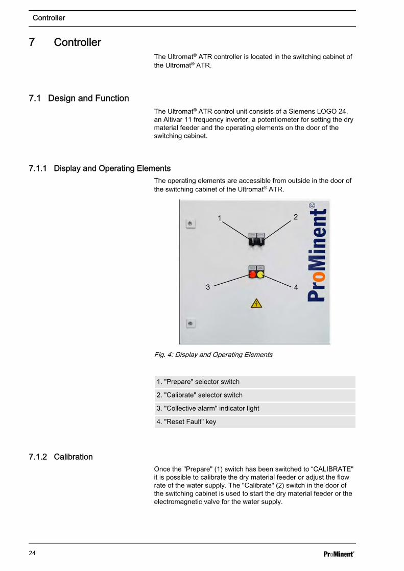
7.1.1 Display and Operating ElementsThe operating elements are accessible from outside in the door ofthe switching cabinet of the Ultromat® ATR.
1 2
3 4
Fig. 4: Display and Operating Elements
1. "Prepare" selector switch
2. "Calibrate" selector switch
3. "Collective alarm" indicator light
4. "Reset Fault" key
7.1.2 CalibrationOnce the "Prepare" (1) switch has been switched to “CALIBRATE"it is possible to calibrate the dry material feeder or adjust the flowrate of the water supply. The "Calibrate" (2) switch in the door ofthe switching cabinet is used to start the dry material feeder or theelectromagnetic valve for the water supply.
Controller
24

7.1.2.1 "CALIBRATE POWDER – 0 – WATER"
Once the "Calibrate" switch has been switched over to "CALI‐BRATE-POWDER", the frequency inverter on the dry materialfeeder starts up. The frequency can be adjusted between 0 - 100Hz by means of a potentiometer in the switching cabinet.
Once the "Calibrate" switch has been switched to "CALIBRATEWATER", the electromagnetic valve at the inlet opens up the watersupply.
7.1.3 Mode: Prepare "0"Once the "Prepare" switch has been switched to Prepare "0", theelectrical heating in the metering pipe continues to be active.
The agitators continue to be active.
The preparation of the polymer solution is stopped.
It is still possible to remove the polymer solution from reservoir 3,even when the switch is set to "0", providing that there is still pol‐ymer solution in reservoir 3.
7.1.4 Mode: Prepare "Auto"When the level falls below the minimum level (LSL) in reservoir 3,the controller starts up the preparation operation. The electro valveon the water supply opens and the dry material feeder starts to dis‐charge the powder once the delay time has expired.
The following screen appears in the display of the Siemens LOGO24 controller:
‘"MAKING UP STOCK"’Once the maximum level (LSH) in reservoir 3 has been reached,the controller firstly switches off the dry material feeder and, oncethe run-on time has finished, closes the solenoid valve in the watersupply.
The following screen appears in the display of the Siemens LOGO24 controller:
‘"DISCHARGE STOCK"’
7.1.5 Mode: Prepare "Remote Control Mode"Material preparation can be switched on and off by a potential-freecontact when the system is in "PREPARE - AUTO" mode. Thestatus display of the "PREPARE - AUTO" switch is provided on theterminal strip in the switching cabinet. The metering process is fullyautomatically controlled, even when the system is remotely con‐trolled by the Siemens LOGO 24 controller.
Controller
25
7.1.6 Setting Control Parameters7.1.6.1 Output Screen
All of the parameters needed to operate the system are enteredinto the controller in PREPARE - "0" mode.
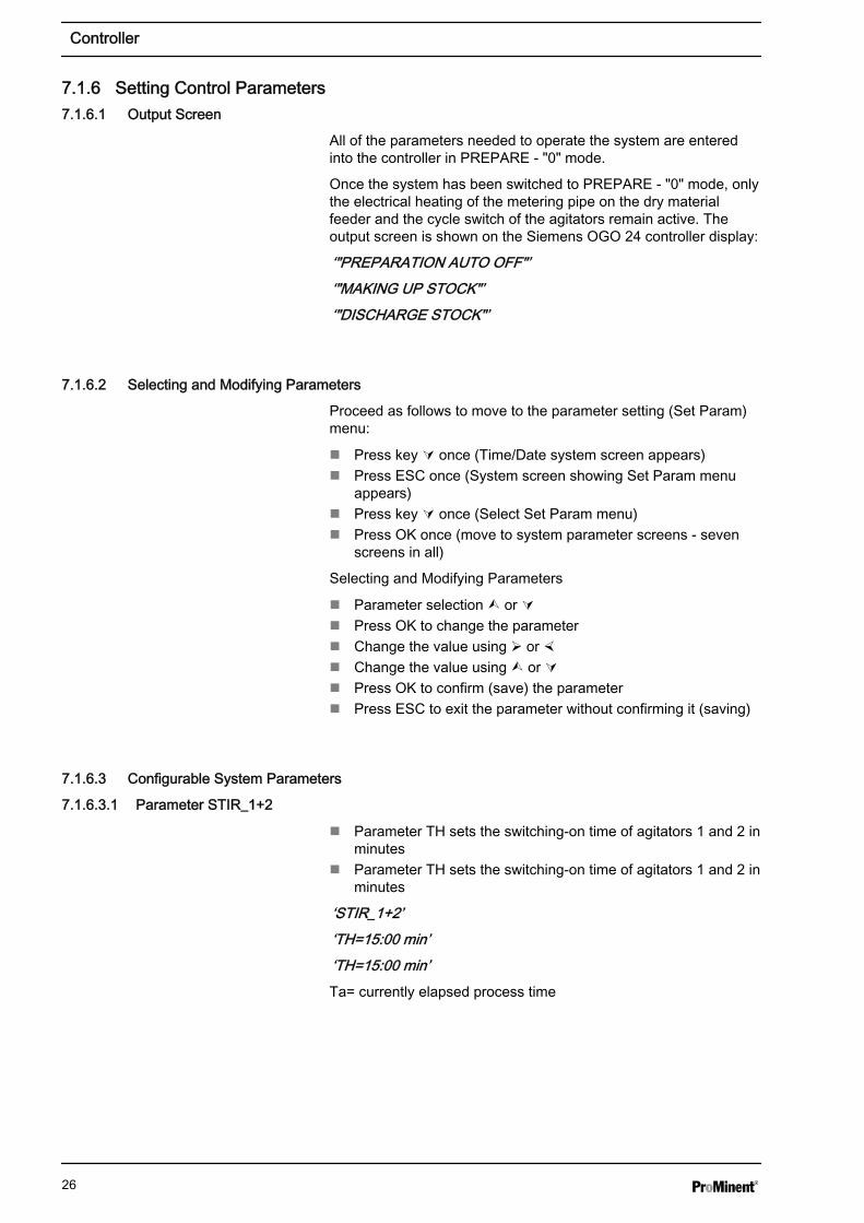
Once the system has been switched to PREPARE - "0" mode, onlythe electrical heating of the metering pipe on the dry materialfeeder and the cycle switch of the agitators remain active. Theoutput screen is shown on the Siemens OGO 24 controller display:
‘"PREPARATION AUTO OFF"’‘"MAKING UP STOCK"’‘"DISCHARGE STOCK"’
7.1.6.2 Selecting and Modifying Parameters
Proceed as follows to move to the parameter setting (Set Param)menu:
n Press key Ú once (Time/Date system screen appears)n Press ESC once (System screen showing Set Param menu
appears)n Press key Ú once (Select Set Param menu)n Press OK once (move to system parameter screens - seven
screens in all)
Selecting and Modifying Parameters
n Parameter selection Ù or Ún Press OK to change the parametern Change the value using Ø or ×n Change the value using Ù or Ún Press OK to confirm (save) the parametern Press ESC to exit the parameter without confirming it (saving)
7.1.6.3 Configurable System Parameters
7.1.6.3.1 Parameter STIR_1+2
n Parameter TH sets the switching-on time of agitators 1 and 2 inminutes
n Parameter TH sets the switching-on time of agitators 1 and 2 inminutes
‘STIR_1+2’‘TH=15:00 min’‘TH=15:00 min’Ta= currently elapsed process time
Controller
26
7.1.6.3.2 Parameter PRE_RINS
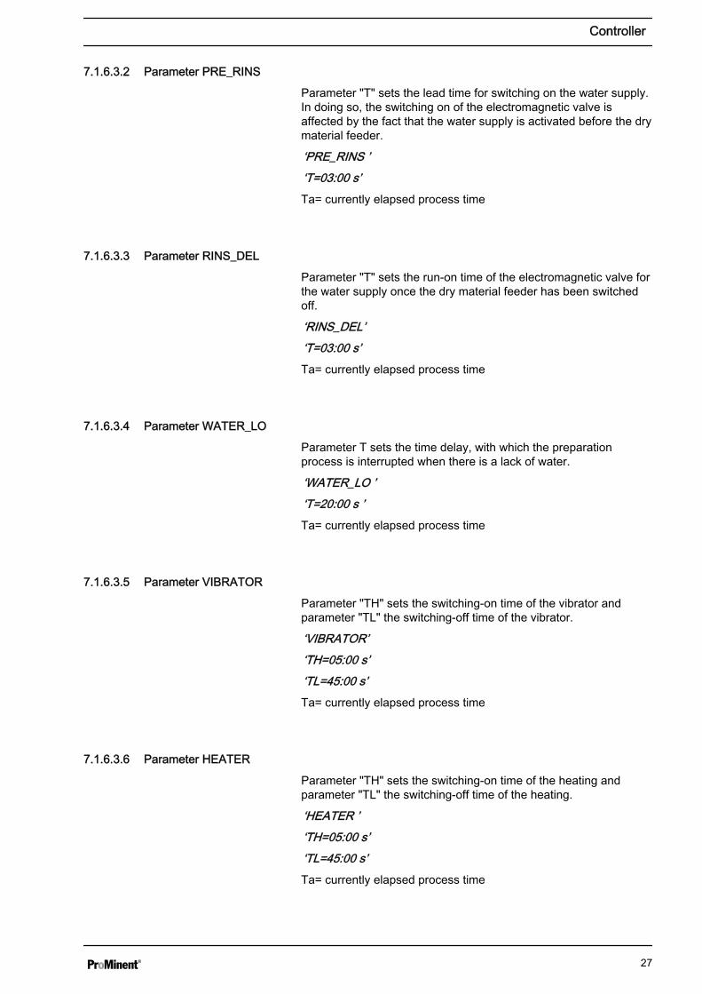
Parameter "T" sets the lead time for switching on the water supply.In doing so, the switching on of the electromagnetic valve isaffected by the fact that the water supply is activated before the drymaterial feeder.
‘PRE_RINS ’‘T=03:00 s’Ta= currently elapsed process time
7.1.6.3.3 Parameter RINS_DEL
Parameter "T" sets the run-on time of the electromagnetic valve forthe water supply once the dry material feeder has been switchedoff.
‘RINS_DEL’‘T=03:00 s’Ta= currently elapsed process time
7.1.6.3.4 Parameter WATER_LO
Parameter T sets the time delay, with which the preparationprocess is interrupted when there is a lack of water.
‘WATER_LO ’‘T=20:00 s ’Ta= currently elapsed process time
7.1.6.3.5 Parameter VIBRATOR
Parameter "TH" sets the switching-on time of the vibrator andparameter "TL" the switching-off time of the vibrator.
‘VIBRATOR’‘TH=05:00 s’‘TL=45:00 s’Ta= currently elapsed process time
7.1.6.3.6 Parameter HEATER
Parameter "TH" sets the switching-on time of the heating andparameter "TL" the switching-off time of the heating.
‘HEATER ’‘TH=05:00 s’‘TL=45:00 s’Ta= currently elapsed process time
Controller
27

7.1.6.3.7 Parameter STIR_3
Parameter TH sets the switching-on time and parameter TL theswitching-off time of agitator 3.
‘STIR_3’‘TH=05:00 min’‘TL=10:00 min’Ta= currently elapsed process time
To return from the parameter setting menu (Set Param) to theoutput screen (if the cursor is not flashing):
n Press ESC twice (Time/Date system screen appears)n Press key × once (Output screen appears)
7.1.7 Fault MessagesShould a fault occur during preparation or discharge of flocculants,the "COLLECTIVE ALARM" indicator will light up on the switchingcabinet and the collective alarm relay will open. The nature of thefault will be displayed on the LOGO controller display in theswitching cabinet.
Once the fault has been eliminated, it can be acknowledged usingthe "RESET FAULT" key.
7.1.7.1 LOGO Controller Fault Messages
7.1.7.1.1 "STIRRERS FAULT" Fault Message
Probable cause:
n Defective motorn Phase failuren Motor protection switch set incorrectly
Delay: 1 s
Remedial measures:
n Check motor and replace if necessaryn Check that all phases are presentn Check power setting on motor protection switch
7.1.7.1.2 "INVERTER FAULT" Fault Message
Probable cause:
n Voltage failure on frequency invertern Internal frequency inverter fault
Delay: 5 s
Remedial measures:
n Check voltage supply to frequency invertern In the event of a fault with the frequency inverter, identify the
cause based on the frequency inverter fault messagen Check and possibly replace dry material feeder drive
"STIRRERS FAULT!"
"INVERTER FAULT"
Controller
28

7.1.7.1.3 "LACK OF POWDER" Fault Message
Probable cause:
n Lack of powder in the storage reservoirn Defective filling level gauge
Delay: 3 s
Remedial measures:
n Add powder to storage containern Check filling level gauge is working correctly - and possibly
replace
7.1.7.1.4 "WATER FLOW LOW" Fault Message
Probable cause:
n Pressure fluctuations in the water supply linen Defective limit flow rate sensorn Electromagnetic valve on water supply not open
Settable delay – Parameter WATER_LO: 20 sec after electromag‐netic valve has been opened
Remedial measures:
n Check pressure of supply watern Check electromagnetic valve and limit flow rate sensor - and
possibly replace
7.1.7.1.5 "STOCK OVERFILL" Fault Message (Optional)
Probable cause:
n Defective LSH level measurement in the Ultromat reservoirn Parameter RINS_DEL too highn Supply water electromagnetic valve has not closedn Water flow rate too high
Delay: 1 s
Remedial measures:
n Check LSH level measurement in reservoir 3n Reduce parameter RINS_DELn Check electromagnetic valven Check water flow rate
7.1.7.1.6 "STOCK LEVELS FAULT" Fault Message
Probable cause:
n Defective level measurement in reservoir 3
Delay: 5 s
Remedial measures:
n Check level measurements in reservoir 3
"LACK OF POWDER"
"WATER FLOW LOW"
"STOCK OVERFILL"
"STOCK LEVELS FAULT"
Controller
29

7.1.7.1.7 "DILUTION FAULT" Fault Message
Probable cause:
n Defective limit switch for water supply to the redilution unitn Electromagnetic valve in the water supply to the redilution unit
not openn Water flow rate in the redilution unit too low
Delay: 3 s
Remedial measures:
n Check limit gauge (the limit switch is closed if water is flowingin)
n Check electromagnetic valve for the water supply to the redilu‐tion unit
n Check and possibly reset water supply flow rate to the redilu‐tion unit
"DILUTION FAULT"
Controller
30

8 Commissioning8.1 Assembly, Preparatory Work
WARNING!– It is essential that the mechanical and electrical
connections are checked to ensure that they arecorrect prior to initial commissioning
– Ensure that the voltage, frequency and currenttype applied in the switching cabinet match thedata on the specification label
– Observe the handling and set-up informationdescribed in Ä Chapter 3.1 ‘Transport and Storageof the System’ on page 15 and Ä Chapter 6‘Assembly and Installation’ on page 22 duringinstallation
NOTICE!– Preparation water, discharge and overflow lines
must be fitted and checked for leakage and correctoperation
– Provide adequate resources in the aforementionedquality
8.2 Settings for CommissioningWhen the unit is delivered, the parameters have the followingdefault settings:
Parameter Default value Range
Heating switch-on time 5 s 1 - 10 s
Heating switch-off time 35 s 30 - 100 s
Supply lead-in time 7 s 0 - 30 s
Supply run-on time 5 min 0 - 30 min
Agitator 1 and 2 Switch-on time 15 min 5 - 50 min
Agitator 1 and 2 Switch-off time 15 min 5 - 50 min
Agitator 3 Switch-on time 5 min 0 - 20 min
Agitator 3 Switch-off time 10 min 5 - 50 min
The parameters can be adapted to the process during commissioning.
Commissioning
31
8.2.1 Water Supply Setting
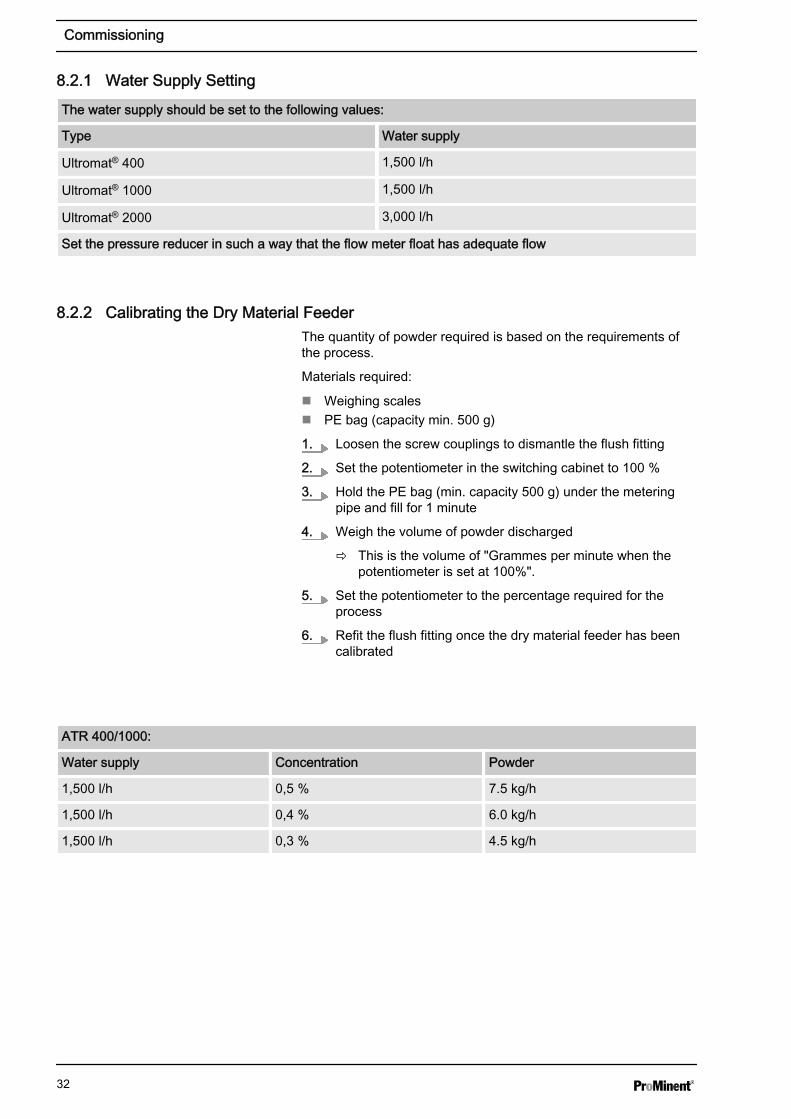
The water supply should be set to the following values:
Type Water supply
Ultromat® 400 1,500 l/h
Ultromat® 1000 1,500 l/h
Ultromat® 2000 3,000 l/h
Set the pressure reducer in such a way that the flow meter float has adequate flow
8.2.2 Calibrating the Dry Material FeederThe quantity of powder required is based on the requirements ofthe process.
Materials required:
n Weighing scalesn PE bag (capacity min. 500 g)
1. Loosen the screw couplings to dismantle the flush fitting
2. Set the potentiometer in the switching cabinet to 100 %
3. Hold the PE bag (min. capacity 500 g) under the meteringpipe and fill for 1 minute
4. Weigh the volume of powder discharged
ð This is the volume of "Grammes per minute when thepotentiometer is set at 100%".
5. Set the potentiometer to the percentage required for theprocess
6. Refit the flush fitting once the dry material feeder has beencalibrated
ATR 400/1000:
Water supply Concentration Powder
1,500 l/h 0,5 % 7.5 kg/h
1,500 l/h 0,4 % 6.0 kg/h
1,500 l/h 0,3 % 4.5 kg/h
Commissioning
32

ATR 400/1000:
Water supply Concentration Powder
1,500 l/h 0,2 % 3.0 kg/h
1,500 l/h 0,1 % 1.5 kg/h
ATR 2000
Water supply Concentration Powder
3000 l/h 0,5 % 15.0 kg/h
3000 l/h 0,4 % 12.0 kg/h
3000 l/h 0,3 % 9.0 kg/h
3000 l/h 0,2 % 6.0 kg/h
3000 l/h 0,1 % 3.0 kg/h
8.2.3 Adjusting the Capacitive SensorThe capacitive sensor for reporting a shortage of powder in the drymaterial feeder must be checked and possibly adjusted:
The sensor has a yellow LED at its cable end to indicate theswitching state and also a sunken adjustment screw to adjust itssensitivity.
Materials required:
n 1 small screwdriver
The sensor is checked and adjusted in 2 steps:
With an empty dry material feeder:
1. If the yellow LED on the sensor is not illuminated - the settingis correct
2. If the yellow LED on the sensor is illuminated:
ð Reduce the sensitivity on the adjustment screw (turn anti-clockwise) until the LED goes out
With a filled dry material feeder:
1. The yellow LED on the sensor is illuminated - the setting iscorrect
2. If the yellow LED on the sensor is not illuminated:
ð Increase the sensitivity on the adjustment screw (turnclockwise) until the LED is illuminated
Commissioning
33
8.3 Setting the Altivar 11 Frequency Inverter8.3.1 Operating Element Functions
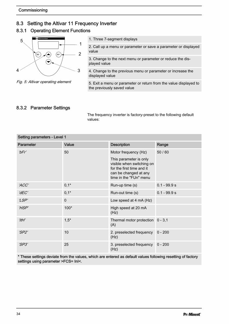
1. Three 7-segment displays
2. Call up a menu or parameter or save a parameter or displayedvalue
3. Change to the next menu or parameter or reduce the dis‐played value
4. Change to the previous menu or parameter or increase thedisplayed value
5. Exit a menu or parameter or return from the value displayed tothe previously saved value
8.3.2 Parameter SettingsThe frequency inverter is factory-preset to the following defaultvalues:
Setting parameters - Level 1
Parameter Value Description Range
‘bFr’ 50 Motor frequency (Hz)
This parameter is onlyvisible when switching onfor the first time and itcan be changed at anytime in the "FUn" menu
50 / 60
‘ACC’ 0,1* Run-up time (s) 0.1 - 99.9 s
‘dEC’ 0,1* Run-out time (s) 0.1 - 99.9 s
‘LSP’ 0 Low speed at 4 mA (Hz)
‘HSP’ 100* High speed at 20 mA(Hz)
‘ItH’ 1,5* Thermal motor protection(A)
0 - 3,1
‘SP2’ 10 2. preselected frequency(Hz)
0 - 200
‘SP3’ 25 3. preselected frequency(Hz)
0 - 200
* These settings deviate from the values, which are entered as default values following resetting of factorysettings using parameter >FCS= InI<.
ESC ENT
1
2
34
5
Fig. 5: Altivar operating element
Commissioning
34

Setting parameters - Level 1
Parameter Value Description Range
‘SP4’ 50 4. preselected frequency(Hz)
0 - 200
‘AIt / ACT’ 4A* Configuration of ana‐logue input (4-20 mA)
* These settings deviate from the values, which are entered as default values following resetting of factorysettings using parameter >FCS= InI<.
"drC" Menu
Parameter Value Description Range
‘UnS’ 230 Nominal voltage of motor(specification label) (V)
100 - 500
‘FrS’ 50 Nominal frequency ofmotor (specificationlabel) (Hz)
40 - 200
‘StA’ 20 Stability of frequencyinverter (%)
0 – 100
‘FLG’ 20 Strength of frequencyregulator (%)
0 – 100
‘UFr 5’ 0 Ri compensation (%) 0 – 200
‘nC’ r 1,5* Nominal current of motorread off rating plate
0,5 – 3,1
‘CLI’ 1,5* Motor limit current 1,0 – 3,1
‘nSL’ 0* Nominal slip rate ofmotor (Hz)
0 - 10
‘SLP’ 0* Slip compensation (%) 0 – 150
‘COS’ 0,78* Cos Phi of motor (specifi‐cation label)
0,50 – 1,00
* These settings deviate from the values, which are entered as default values following resetting of factorysettings using parameter >FCS= InI<.
"FUn" Menu
Parameter Sub-menu Value Description
‘tCC’ Type of control
‘ACt’ ‘2C’ 2-wire control
‘tCt’ ‘LEL*’ Type of 2-wire control
‘rrS’ ‘no*’ Anti-clockwise rotation
‘PS2’ Preselected frequencies
* These settings deviate from the values, which are entered as default values following resetting of factorysettings using parameter >FCS= InI<.
Commissioning
35

"FUn" Menu
Parameter Sub-menu Value Description
‘LiA’ ‘no’ Assignment of input LIA
‘LIb’ ‘no’ Assignment of input LIb
‘tLS’ ‘0,0’
‘PI’ ‘no’
‘rSF’ ‘no’ Switch on again in theevent of a fault
‘rP2’ Second ramp
‘LI’ ‘no’ Assignment of the inputfor controlling the secondramp
‘LC2’ 2. Power limitation
‘LI1’ ‘no’
‘nSt’ ‘no’
‘StP’ ‘no’ Managed run-out in theevent of power failure
‘brA’ ‘no*’ Adjustment of run-outramp
‘AdC’ Automatic infeed directcurrent
‘ACt’ ‘yes’ Operating mode
‘tdC’ ‘0,5’ Infeed time
‘SdC’ ‘1,4’ Infeed current
‘SFt’ Pulse frequency
‘ACt’ ‘LF’ Frequency range
‘SFr’ ‘4’ Pulse frequency (kHz)
‘FLr’ ‘no’ Alignment in operation
‘d0’ Analogue output
‘ACt’ ‘no*’ Assignment
‘Atr’ ‘yes*’ Automatic restart
‘bFr’ ‘50’ Motor frequency (Hz)
‘SCS’ ‘yes’ Save configuration
‘FCS’ Call up configuration
‘no’ Function inactive
* These settings deviate from the values, which are entered as default values following resetting of factorysettings using parameter >FCS= InI<.
Commissioning
36
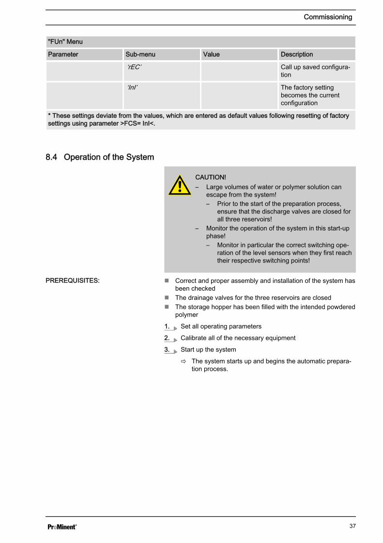
"FUn" Menu
Parameter Sub-menu Value Description
‘rEC’ Call up saved configura‐tion
‘InI’ The factory settingbecomes the currentconfiguration
* These settings deviate from the values, which are entered as default values following resetting of factorysettings using parameter >FCS= InI<.
8.4 Operation of the System
CAUTION!– Large volumes of water or polymer solution can
escape from the system!– Prior to the start of the preparation process,
ensure that the discharge valves are closed forall three reservoirs!
– Monitor the operation of the system in this start-upphase!– Monitor in particular the correct switching ope‐
ration of the level sensors when they first reachtheir respective switching points!
n Correct and proper assembly and installation of the system hasbeen checked
n The drainage valves for the three reservoirs are closedn The storage hopper has been filled with the intended powdered
polymer
1. Set all operating parameters
2. Calibrate all of the necessary equipment
3. Start up the system
ð The system starts up and begins the automatic prepara‐tion process.
PREREQUISITES:
Commissioning
37
9 Operation of the System9.1 Normal Mode9.1.1 Prerequisites for Correct and Proper Operation
Prerequisites:
n Correct setting of operating parametersn No unauthorised parameter changes on frequency inverter
WARNING!The system may only be operated by instructed per‐sonnel!
– The system can in principle be stopped andrestarted in every operating phase
– As a rule, the cause of a fault should be eliminatedbefore the relevant fault message has beenacknowledged
9.1.2 Feeding the Storage Hopper with Powdered Polymer
CAUTION!Danger of slipping!Mixtures of polymer and water are slippery!
– Ensure that you have a secure foothold when fillingthe powder hopper!
– Immediately remove any spilled powdered polymeror leaked polymer solution!
If the storage hopper is not automatically filled, the supply of pow‐dered polymer has to be continuously checked and refilled in time.This can be done while the system is operational. To do so,remove the lid of the storage hopper and carefully add in powderedpolymer.
9.2 Behaviour When Switching on Mains Power and in the Event of Mains PowerFailure
a) Switching on mains power
n Each time mains power is switched on, the agitators start upwithout regard to the system status measured
n In contrast, the system only starts up with preparation once theminimum switching-on point in reservoir 3 has been reached
b) Switching off mains power
n Following power failure, which results in the controller beingrestarted, the controller will unrestrictedly continue with theoperation of the system based on the status measured
n If the level of the storage container is within the regular range,no preparation operation will be started even if a preparationprocess was running prior to the interruption
Operation of the System
38
9.3 Decommissioning
WARNING!It is imperative that the following is noted should thesystem have to be moved or stored: Ä Chapter 3‘Transport and Storage of the System’ on page 15 .
Switch to Prepare "0"
1. Set the main switch to "0"
2. Lock the main switch to prevent the system from beingswitched on accidentally
1. Set the main switch to "0"
2. Lock the main switch to prevent the system from beingswitched on accidentally
3. Disconnect the mains supply
4. Completely empty the dry material feeder
5. Empty the three-chamber reservoir through the connectionson the individual reservoirs provided for this
6. Carefully flush the reservoirs with water
7. Additionally flush fittings (hopper and mixing equipment)
8. Carefully flush the line between the shut-off fitting on reser‐voir 3 and the feed pump
9.4 Disposal
CAUTION!– Please observe the currently applicable local regu‐
lations (specifically with regard to electronicwaste)!
– Please also read the operating instructions for theother equipment (dry material feeder, pumps ...)!
For Germany: The cleaned used parts can be disposed of atmunicipal waste collection points.
For a short period
For a longer period
For more than two days
Operation of the System
39
10 Incorrect Operation of the Systemn The incorrect position of the discharge valves can result in mal‐
functionn The incorrect position of the shut-off valves in the water supply
line can result in malfunctionn Unauthorised persons must be prevented from entering or
changing operating parametersn The preset parameter values for the frequency inverter may not
be changed as they are factory-set on the dry material feedern When setting the concentration, the maximum viscosity limit of
1500 mPas may not be exceededn Failure to refill the polymer storage container will stop the
systemn Further more serious faults may occur should the system be
operated without the original faults having been eliminated
Incorrect Operation of the System
40

11 Troubleshooting
CAUTION!Danger of sudden start-up!
– The agitators and propellers may start up suddenly
NOTICE!The operating instructions for additional parts shouldbe read when eliminating functional faults!
Collective alarm
A system fault/malfunction (collective alarm) is acousticallyreported with a warning sound and visually by the red warning lighton the switching cabinet. The controller also displays a fault mes‐sage. The activation of the downstream feed pump (polymer solu‐tion) remains unaffected by the collective alarm.
Acknowledgement
The error message has to be acknowledged with the Quit key oncethe cause of the fault has been eliminated so that the system canrestart its operation following the fault.
Unspecified malfunctions
Should a problem occur, which is not included in this list or shoulda listed fault not be remedied by the suggested troubleshootingmeasures, please contact ProMinent Customer Services withoutdelay.
Troubleshooting
41

12 Maintenance12.1 Inspecting the Dry Material Feeder
Dry Material Feeder
n Inspect the dry material feeder regularly during operation toensure that it is working correctly
n Check whether the powdered polymer is being metered cor‐rectly
12.2 Cleaning the Screen Insert in the Pressure ReducerClean the screen insert at the latest when 2/3 of the throughputsurface of the screen insert is dirty.
1. Switch the "Prepare" switch to "0" to dismantle the screeninsert
2. Manually close the shut-off valve upstream of the pressurereducer
3. Please refer to the manufacturer's instructions in theAppendix for further steps
12.3 Dismantling the Cover of an Inspection Opening
WARNING!Propellers are rotating in the reservoirs!– Set the main switch to "0"and ensure that it cannot
be switched on again– Remove the screwed cover of an inspection
opening
The system must only be operated in principle whenthe inspection openings are tightly screwed. Thecovers may only be removed temporarily. After theinspection work, replace all covers and screw closed!
12.4 Cleaning the Surface of the Ultromat®
If necessary, clean the surfaces of the Ultromat® , as a slippery filmcan build up on them in time.
Maintenance
42

13 Spare Parts and Accessories13.1 Spare Parts
Spare parts can be purchased from our Customer Service depart‐ment.
13.2 AccessoriesAccessories can be purchased from our Customer Service depart‐ment.
Spare Parts and Accessories
43

14 Declaration of Conformity
Fig. 6: EC Declaration of Conformity
Declaration of Conformity
44

15 Commissioning Report
Commissioning Report
45