operating instructions - tsi | precision measurement …€¦ · · 2018-02-23working pressure of...
TRANSCRIPT

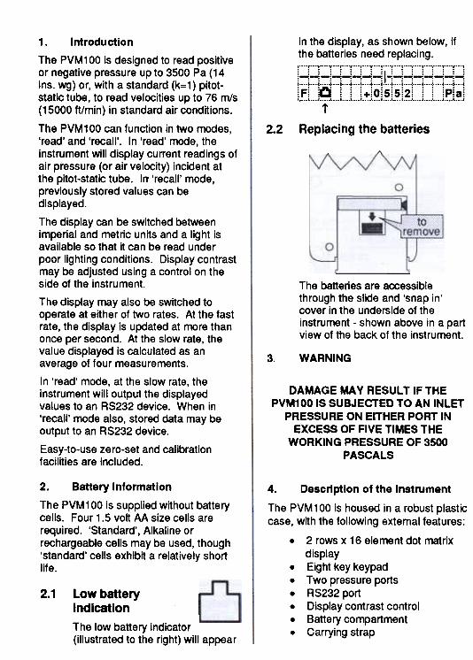
Operating Instructions
Pr9$Ure
~ ports
r +b tj-" ""'
I ;
Display
RS232 port
(on side ) AIRr=lOW-PVMloom"'
Display rate key
Velocity/Pressure key
Display contrastcontrol (on side )
Imperial/Metric key
\' On/off I(S'f-faat
a..
on .
Display light keyI~
-,\'---'
Instrument mode key
~
--Memory store keyZero key
\
Carrying strap
Please read these instructions carefully before using the instrument.Shortform instructions are on the back of the instrument.
in the display, as shown below, if
the batteries need replacing., v...,...v...,...v...,...v...,...v..., , , ,...,, , , ., , ., ., , , .
'"...,..." ' , , ' , , ,..., ,...,
i
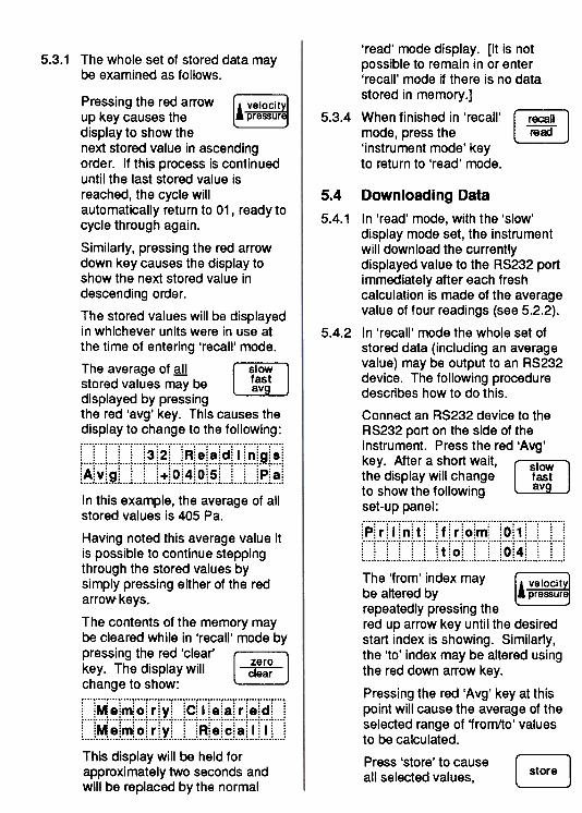
Replacing the batteries2.2
1\
0
p
0
.
The batteries are accessiblethrough the slide and 'snap in'cover in the underside of theinstrument -shown above in a partview of the back of the instrument.
3. WARNING
DAMAGE MA y RESULT IF THEPVM100 IS SUBJECTED TO AN INLET
PRESSURE ON EITHER PORT INEXCESS OF FIVE TIMES THE
WORKING PRESSURE OF 3500PASCALS
1. Introduction
The PVM1 00 is designed to read positiveor negative pressure up to 3500 Pa (14ins. wg) or, with a standard (k=1) pitot-static tube, to read velocities up to 76 m/s(15000 ft/min) in standard air conditions,
The PVM 100 can function in two modes,'read' and 'recall'. In 'read' mode, theinstrument will display current readings ofair pressure (or air velocity) incident atthe pitot-static tube. Irr 'recall' mode,previously stored values can be
displayed.
The display can be switched betweenimperial and metric units and a light isavailable so that it can be read underpoor lighting conditions. Display contrastmay be adjusted using a control on theside of the instrument.
The display may also be switched tooperate at either of two rates. At the fastrate, the display is updated at more thanonce per second. At the slow rate, thevalue displayed is calculated as anaverage of four measurements.
In 'read' mode, at the slow rate, theinstrument will output the displayedvalues to an RS232 device. When in'recall' mode also, stored data may beoutput to an RS232 device.
Easy-to-use zero-set and calibrationfacilities are included.
2. Battery Information
The PVM 100 is supplied without batterycells. Four 1.5 volt M size cells arerequired. 'Standard', Alkaline orrechargeable cells may be used, though'standard' cells exhibit a relatively shortlife.
2.1
4. Description of the Instrument
The PVM100 is housed in a robust plastic
case, with the following external features:
.2 rows x 16 element dot matrix
display
.Eight key keypad
.Two pressure ports
.RS232 port
.Display contrast control
.Battery compartment
.Carrying strap
Low battery
indication
The low battery indicator(illustrated to the right) will appear

4.2 Keypad functions
Keypad keys are marked in twocolours. The white colour denotescommands which apply to the'read' mode. The red colourdenotes commands which apply tothe 'recall' mode.
4.2.1 Press the 'on/off' key. ~The display will come L~on within a second orso. On start-up, the instrumentwill enter 'read' mode with thedisplay at the 'fast' rate (an 'F'appears in the bottom left corner ofthe display). The display units willbe the same as those in use thelast time the instrument was used.Pressing the key a second time willswitch the instrument off.
4.2.2 When pressed, the ~'Display light' key will ~light the display forapproximately 6 seconds. It is notnecessary to hold the key down.
4.2.3 The 'instrument mode' r-~ 1key toggles the L ~ J
instrument between'read' and 'recall' modes.
4.2.4 The 'Memory store' r ~.~.~ 1key, when pressed, ~causes the datacurrently being displayed to bestored in memory.
4.2.5 In 'read' mode, the r ~~O!f 1'Display rate' key ~toggles between 'slow'and 'fast' display rates. In 'recall'mode, the key causes the averageof stored data to be displayed.
4.2.6 In 'read' mode, the r~-;;;;y]
'velocity/pressure' key L.priiSijriiJtoggles the displaybetween velocity and pressuredata. In 'recall' mode, the key
Items supplied with the PVM 100 but notforming part of the instrument itself are:
.Carrying case
.Mating RS232 connector (mini 8pin plug, Airflow Part No.
9040180).2.Smm to Smm tube adaptors (for
connecting to standard pitot-static
tubes).2.Smm I.D. x 2m lengths of red
and blue plastic tubing.Smm I.D. x 1S0mm lengths of red
and blue plastic tubing
NOTE: Connect adaptors and tubingas shown in diagram in Section 7.1.
4.1 The Display
The display in 'read' mode isshown above. The top rowprovides a simple linear bar graphof the incoming pressure. The bargraph has a centre zero and showspositive values as a line extendingto the right and negative to the left.
The bottom row shows Displayrate ('F' or'S') in the left mostelement, the 'light' symbol(whenever the display light is on -
see paragraph 4.2.2) in the secondelement along and the 'low battery'symbol (when applicable) in thethird element along.
i.~l.~j l...l...l...l~l.~l~.l.~j.~l...l...L..l~L~j
1 l~.~.l~.~.l.~j.y.l...i...l~i~.l.~i~.l.!.i.~.l...j
In 'recall' mode, as illustratedabove, the top row of the display isused to indicate each stored valueand the bottom row the legend'Memory Recall' or the average ofthe stored values, if socommanded (see paragraph 5.3).

The Display Contrast Control4.4enables a sequence of storeddata to be displayed inascending order.
4.2.7 In 'read' mode, the ~ . 1,. .., m erls
Impenal/metrlc key' me rlc
toggles the displaybetween imperialand metric units.
In 'recall' mode, the key enablesa sequence of stored data to bedisplayed in descending order.
4.2.8 In 'read' mode, the r ~ 1
'Zero' key enables ~
the instrument to setits own offset to zero, with nodifferential pressure applied tothe instrument. It is notnecessary to hold the key down.
In 'recall' mode, the key causesthe memory to be cleared.
) .i ~
DISPLAY CONTRASTCONTRa.
Also located on the side of theinstrument, this control may beused to vary the display contrast.This control should not normallyneed any adjustment but if thedisplay contrast is not optimum forany reason, a small screwdrivermay be used to make an adjust-ment.
4.3 The RS232 Port
\>t: (
RS232 PORT
5. OperatLon
Before making any pressure connectionsit is wise to press the 'zero' ~ ; .zero ,
key to reset the Instrument's clear !
offsets.
Connect the instrument to a remotepressure source. Positive pressurereadings will be obtained if the pressure(relative to atmospheric pressure)connection is made to the left-hand porton the top of the instrument, negative tothe right-hand port -see illustration whichfollows.
5.1 Switch On
Press the 'on/off' key. r-;;-The display will show ~the current computedvelocity or pressure value.
Located on the side of theinstrument, the RS232 port is amini 8 pin DIN female socket.
It may be used to connect theinstrument to any RS232compatible device such as aprinter or data-Iogger.
The RS232 interface is suitablefor driving a SEIKO Model No.DPU201 GS (obtainable throughAirflow Ltd) or any other RS232
co~atible printer.
Connection details and dataformat are given in Section 10 atthe end of this booklet.

'store' key. The display r ~ 1
will change (for four ~
seconds) to show thevalue being stored, as follows:
, ,..., , ,..., , ,...'"...,...'"...,..., ,;0;1: : ; : ;+;0;5;5:2: : ; ;P:a;f...i !...f...f...f...!...i f...i f...f..-!...f...f...f...i;F; ; ; : : ;+:0;5;5;2: : : ;P;a:;...; ,...; ,...; ,...; i...; ,...; ,...; i...; ;
Up to 60 values may be stored.
Note that the reading is stored as avelocity or pressure value in theunits currently in use. Thus, whenstoring a series of readings, it isimportant that neither thevelocitv/Bressure nor theimDerial/metric kevs should beBressed. If such a change is madeimmediately prior to recalling thestored data, all stored values willbe displayed in the new units(rather than the units in which theywere originally recorded).
5.2.4 Note that due to the high sensitivityof the instrument, low pressurefluctuations such as noise, arefiltered out. Hence, for inputsbelow the levels specified in thefollowing table, the display willshow zero:
5.3 Recalling Stored Data
Press the 'Instrument ~
mode' key to switch to l~J
the 'recall' mode. The
display will change to show the
first item of stored data on the top
row with the legend 'Memory
Recall' on the bottom row -as
shown in the following illustration:
iOi1 i i: i i+iO:SiSi2: i i :P:ai
;...; ;...; ;...; ;...; ;...; ;...; ;...; ;...; j
L. .1. ~ .~ ~ ~ 1..~ .l ~ j. ..1. ..1.~!~1.~1.~1. ! l.~.l.. .!
5.2 'Read' Mode Measurements
5.2.1 The instrument will enter 'fast'mode automatically on switch-onand will display either velocity orpressure values -depending onwhich mode it was in when lastused.; ' ' ' '...' ' '...' ,..., , ,
In the above example, the top rowis the linear bar graph of thepressure as described earlier, the'F' confirms that the instrument isin 'fast' mode and the currentreading is a pressure of 552 Pa.
Press the r, velocltyl
'velocity/pressure' key lAPf9SSUf8jto toggle between'velocity' and 'pressure' values.
Press the ~ Im erlal'imperial/metric' key to l' miffii:ltoggle between imperialor metric units on the display.
5.2.2 With the instrument set to displayat the 'fast' rate, the display will beupdated at a rate slightly higherthan once per second (and willdisplay an 'F' in the lower leftcomer of the display).
If the 'display rate' key r ~~~ 1is pressed, the display ~will show an average offour readings, updatedapproximately once every threeseconds (and will display an'S' inthe lower left corner of the display).
In the 'slow' mode, the data beingdisplayed is output to the RS232
port.
5.2.3 At any time while readings arebeing taken, it is possible to storeany reading (currently showing inthe display) in the instrument'smemory. To do this, press the
5.3.1 The whole set of stored data maybe examined as follows.
'read' mode display. [It is notpossible to remain in or enter'recall' mode if there is no datastored in memory.]
5.3.4 When finished in 'recall' r ~ 1mode, press the l-~-J'instrument mode' keyto return to 'read' mode.
5.4 Downloading Data
5.4.1 In 'read' mode, with the 'slow'
display mode set, the instrument
will download the currently
displayed value to the RS232 port
immediately after each fresh
calculation is made of the average
value of four readings (see 5.2.2).
5.4.2 In 'recall' mode the whole set of
stored data (including an average
value) may be output to an RS232
device. The following procedure
describes how to do this.
Connect an RS232 device to the
RS232 port on the side of the
instrument. Press the red 'Avg'
key. After a short wait, OOIOW the display will change fast
to show the following av
set-up panel:
!.~[.~j..I..[~j.~.l...j..~.l.~j..C?[~L..j.~.l.~.j L.j j
! l...j l...j l...l~.l.~j l L..L~.l~j L..j !
The 'from' index may r & velocityl
be altered by l.1ifi-ssimiJ
repeatedly pressing the
red up arrow key until the desired
start index is showing. Similarly,
the 'to' index may be altered using
the red down arrow key.
Pressing the red 'Avg' key at this
point will cause the average of the
selected range of 'from/to' values
to be calculated.
Press 'store' to cause r ~.~.~ 1
all selected values, ~
Pressing the red arrow r~~;;~l
up key causes the l~
display to show the
next stored value in ascending
order. If this process is continued
until the last stored value is
reached, the cycle will
automatically retum to 01, ready to
cycle through again.
Similarly, pressing the red arrow
down key causes the display to
show the next stored value in
descending order.
The stored values will be displayed
in whichever units were in use at
the time of entering 'recall' mode.
The average of all r ~~o~v:' 1
stored values m-ay be ~
displayed by pressingthe red 'avg' key. This causes the
display to change to the following:
In this example, the average of all
stored values is 405 Pa.
Having noted this average value it
is possible to continue stepping
through the stored values by
simply pressing either of the red
arrow keys.
The contents of the memory may
be cleared while in 'recall' mode by
pressing the red 'clear' r ~ 1
key. The display will ~
change to show:, , , ~ ,...,...~..., ,..., ,...,
L.l~.~j~j.~.l.~.J.y.l...j.~l.~.J.~.l~j.~.l~j.~.L.j
~..j.~.~!.~J.~.l.~j.y.i...j ~~J.~.i.~j.~.L~.j..I..L.j
This display will be held for
approximately two seconds and
will be replaced by the normal

plus the average of these values,to be output to the RS232 device.Once the output sequence iscomplete, the display will return tothe normal 'Memory Recall' one.
'velocity/pressure''imperial/metric'
Each correct entry will be indicatedbya '*' on the display.
If1here is an incorrect entry, thePVM 100 will start-up again but inthe normal 'read' mode. If thishappens, press the 'on/off' key andstart again from switch on asdescribed in paragraph 6.1.2.
Once the code is entered correctly,the display will show:
f...1.~f.~1.~!...+X!.~.~~! f~!.~.~.~.!.~.f...j.~.f...i:Y:=:z:e:r:o: : :N:=:I:I: 9 :h:t: ::...; :...; : :...: ,...: :...: ,...:. .:...: :...;
~ Press 'zero' toB~ continue or 'light' light
to quit.
6. Calibration
Given that a calibrated pressure source(with a range of zero to 3500 Paminimum) is available, re-calibration ofthe PVM100 using its built-in calibrationfacility is a very simple process.
To ensure accuracy, the pressure sourceshould be traceable to a NationalStandard.
WARNING: Altering the calibration willINVALIDATE Airflow's warranty. Notethat the PVM 100 will monitor each timethe calibration is affected.
If the calibration routine isINADVERTENTL Y entered then SWITCHOFF immediately and re-start.
6.2 Calibration Procedure
Calibration of the PVM 100 is
highly simplified and involves no
internal adjustments. The
procedure merely requires the user
to select the correct pressure and
proceed through a series of
instructions displayed on the
PVM1 OO's display.
The PVM1 00 is calibrated by
selecting four different pressure
points, firstly on the positive
pressure port and secondly on the
negative pressure port. The
calibration instructions are
prompted by the PVM 100 at each
step, as follows:
6.2.1 Prompt:, , y y y , l~j.~.l.~j...j.~.L~.L~.l~j.~ .[~j.~.l~L~.[~j.~l.~j
[!).~.L~).~j l~j.~.:.~j.~.L.j.~.:.~j.~.l~! L.j
With the positive pressure port
connected to the pressure source,
set the pressure to 0000 Pa.
Press the 'zero' key on the
PVM100's keypad.
6.1 Set-up
6.1.1 Connect the positive port of the
PVM100 to the pressure source.
6.1.2 Switch on the PVM 100, wJlj]g
holdina down an~ other ke~ on the
kemad. The display should show:
, ,, ... V 1 ., .. N.'
N L...l...l..l.~l.~j..S:l...l~.l~L..l...j.:..l...l...l...l...i
~.~l~j l l...L..l..J l...L..l...L...l..J l...j ~
where N.N is the current software
issue, and XX is the value of the
calibration counter (for Airflow use
only).
If the display does not show this,
switch off and repeat the switch-on
step again.
6.1.3 Press the keys listed in the
following (and in the order listed)
to enter the calibration routine
code:
'slow/fast/avg''zero/clear'

6.2.2 Prompt:
~~j. ~.~ .~ .j.. ..j.~~. ~.1. ~ .~ ~ j. .8: .~=j. ~.~~ j. ~ .~~ j .~. ~ ~ j
l!l ~ l.~ 1!:'.1..1 ~J. ~ .l ~ j. ~ .L ..J. ~.l ~ j. ~l ~ J. ..1. .j
Increase the pressure to 3500 Pa
and, when stable, press the Izero'
key on the keypad.
6.2.3 Prompt:
keypad and the following prompt
will appear:
,...v..., ,..., ,..., ,..., ,..., ,..., , ,. V . / . p D ..~~. I ... d .:::::=::+:::o:":n::o:a::
r...t...t...!...t...r..t...r...t...r..t...i.t...~ t...1 ::1:/:M :=: :-: :Do:w:n:l:o:a:d:; ;...; , L..; : ; L..; : ; ;...; : ; 1
If the positive port has
just been calibrated, r~l
then press 'velocity/ l~~
pressure' (or r. imperiall
'imperial/metric' if the ~
negative port has just
been calibrated).
NB Take care at this point to press
the correct key, otherwise
calIbration wIll have to be done
again for both sides of the
transducer.
At this point, the PVM 100 will be
storing the calibration data.
6.2.7 Once it has stored the calibration
data, the PVM 100 will display the
following prompt:
,..., ,...v...v...,..., ,...,...y...,...y...,...y...v...,
:S:e:t: :P:r:e:s:s:-:O:O:O:O:P:a:! !...j ! !...j ;...!...~...j.:7+...j...~...j...+...j !
i.!. L~j.~. L ~ .L. j .~.1. ~ j .~.l~ i. ..J.~j .~ .L ~j. ~ .L. j. ..J
Connect the negative port to the
pressure source and repeat steps
6.2.1 through 6.2.6.
6.2.8 On completion of this negative
calibration process, switch off the
PVM 100 and then switch on again
normally. The display should show:
,..., ,...v...v..y...v..y...,...y...,...v...,...y...v...,
i !...i ! f...!...+...! f...!...+...! f...!...+...i i
L .L. j. ...L... L. j ..,,:.l ~j .~.l ~ j. ~ .1. ~i.~.L. j. ...L.J. ...i
---and should respond to changes
in pressure upon its ports. Try the
range of pressures described in
paragraph 6.2.5. If an accurate
zero cannot be achieved, press the
'zero' key, and then try again.
~ ~~.~.~ .~.~. ...1.~~ .~~.~.~~ 1.~.~=1.! .~! j. ~ .~~ 1. ~. ~~ ~
l!!.~.l~j.~j l~j.':.J.l~j.~.L..L~.l~j.~.l~j L.J
Decrease the pressure until slightly
below 1750 Pa and then increase
up to 1750 Pa. When stable,
press the 'zero' key on the keypad.
6.2.4 Repeat step 6.2.3 for 875 Pa.
6.2.5 The display will now show:
,..., ,..., ,...y..., ,".., ,..., ,..., ,..., ,...,
iC:ail:l;biriaitilioin;;iiii
!...i !...i ! !...!...+...! !...! ~...! !...! !...i
Lj Lj...j.~.[~j.!.[~j.~.[~J...l..j L.J Lj
The PVM100 is now calibrated in
the positive direction, and will
operate normally (but in the
~ositive direction onl~). The
calibration should now be checked
as follows.
Set the pressure source to the
settings listed below. The PVM100
will measure the pressure as it
changes and display the new
value(s). Check that the PVM 100
readings now correspond to the
pressure source (or are within an
accuracy of :t1% of reading) at
each of the following range of
values:
0 Pa100 Pa
1000 Pa2000 Pa
6.2.6 Once the calibrationhas been checked,press 'zero' on the
r~l
~
7.2 Air Filter Pressure Loss
In a similar manner, the instrumentmay be used in 'pressure' mode tomeasure the static pressure eitherside of an air filter in a duct.
In this case, a single measurementonly is required on the upstreamand downstream sides of the filter.The difference between the twopressure readings is an indicationof the state of the filter.
Measure the cross-sectional areaof the duct (using metres or feetunits as appropriate to the velocityunits used).
Calculate the volume flow rate as:
Flow rate = (Avg vel) x (area)
The units for the flow rate answerwill be either m3/sec or ft3/min,depending on whether metric orimperial units were used.
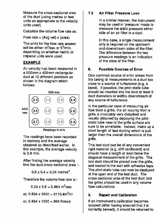
EXAMPLE
Air velocity has been measured ina 600mm x 400mm rectangularduct at 12 different positions asshown in the diagram whichfollows:
600 mm
§
@
@
@
@
e
400nm
Readings in mls
The readings have been recordedin memory and the averageobtained as described earlier. Inthis example, the average velocityis 3.6 m/s.
After finding the average velocity
find the duct cross-sectional area :-
20.6 X 0.4 = 0.24 metres .
8. Possible Sources of Error
One common source of error arises fromthe taking of measurements in a duct tooclose to a source of turbulence (e.g, abend). If possible, the pitot-static tubeshould be inserted into the duct at least 6duct diameters or widths downstream ofany source of turbulence.
In the particular case of measuring airflow from a grille, the air issuing from agrille is invariably very disturbed andresults obtained by deploying the pitot-static tube near to the grille surface aresure to be unreliable. Instead, make up ashort length of test ducting which is justlarger than the overall dimensions of the
grille.
This test duct can be of any convenientrigid material (e.g, stiff cardboard) andshould have a length at least twice thediagonal measurement of the grille. Thetest duct should be placed over the grille,and sealed to the wall with adhesive tape.The pitot-static tube can now be deployedat the open end of the test duct. Thecross-sectional area of the test duct (notthe grille) should be used in any volumeflow calculations.
Therefore the volume flow rate is:-
0.24 x 3.6 = 0.864 m3/sec
or, 0.864 x 3600 = 311 0.4m3/hr 9. Repair and CalIbration
If an instrument's calibration becomessuspect (after having ensured that it iscorrectly zeroed), it should be returned to
or, 0.864 X 1000 = 864 litres/s

Wiring details for the SEIKO printer(Model No. DPU201 GS) are shown in thefollowing illustration:
~ PVM100
DATA -3 E-= 3- TX..
SG -5 L 5 -SG..
BUSY -8 ; 8 -CTS
Wiring details for other typical printerswith an RS232 port (on a 9 pin O-typeconnector) are shown in the followingillustration :
TYPICAL
PRINTER
RD -2 SG -5 DTR -4
Airflow Developments for recalibration tooriginal standards. In any event, it isgood practice to have the instrumentchecked at least once a year.
If an instrument is not working correctly,or requires recalibration, contact yournearest Airflow Agent or UK ServiceDepartment on (01494) 525252.
In the UK, Airflow Ventilation Supplies(AVS) operates an instrument hire servicefor the convenience of customers havingequipment repaired or recalibrated. Touse this facility, contact AVS, telephone(01494) 463490, facsimile (01494)471507, to make arrangements prior toreturning your instrument. PVM100
, 3 -TX,~ 5 -SG,
C-'° 8 -CTS
10. RS232 Connections
A mating RS232 connector (mini DIN 8pin plug, Airflow Part No.9040180 issupplied with the PVM100. The pinidentification for this plug is shown in theillustration which follows:
EXTERNAL VIEW
As indicated, in both cases multicorecable should be used.
The data format for the RS232 outputfrom the PVM100 is as follows:
BAUD 1200
PARITY NONE
DATA BITS 8
STOP BIT 1

11. Specification
I Parameter
I Velocity rangel
i Pressure rangel,
Pressure resolution
Storage temperature
Operating temperature
Accuracy at 20°C
Output
Max. overload pressure
Memory size
Instrument dimensions
Instrument weight (less
battery cells)
Battery cells
Metric mode
O -76 m/s
0 -3500 Pa
1 Pa
-10°C to +50°C
-5°C to +50°C
Imperial mode
0 -15000 ftlmin
0 -14 in wg
0.001 in wg
14°F to 122°F
23°F to 122°F
:t1 % of reading :t 1 digit in +ye and -ye mode
I RS232 (1200,N,8,1 )
17.5 kPa I 70 in wg
60 concurrent velocity or pressure readings
17.28x3.62x1.18ins185 X 92 x 30mm
290 gms 10.3 oz
Four type AA 1.5 volt cells, Rechargeable, Alkalineor Standard (zinc carbon)
Battery life Approximately 35 hours using Alkaline battery cells(in 'read' mode with no backlight or RS232 output)
t Velocity and pressure ranges quoted apply to measurements made on airat a density of 1.2Kg/m3 and using an ellipsoidal nose pitot-static tube toISO 3966 -1977 (BS1042 Section 2.1)
QUALITY ASSURED TO ISO 9001
Airflow Developments Umited, LBncaster Road, AIRfLOW WFmOCHNIK ""'"'" -'208. D530.9. --Cr8SSeX Business Park. High Wycombe. T-~ T-~".Buckinghamshire HP12 3QP. England AIRfLOW TECHNK;AL PR)OlJCTS ""'.23 -A -NJ 07..7 us..Telephone. (014Q4) 525252/443821 T-20'...' F",,20,...,-47mF~knile. (01494) 461073 ..RFLOWUJFTtECtN."",",.0 520.'~00 '0--.C E-mail: infoOairflow.co.uk T-..Iax~-7722,",
WWW. http://www.airflow.couk