operating instructions - | stepcraft - cnc-fräsen für ... · always ensure you understand the...
TRANSCRIPT

1
Operating
instructions
Original operating instructions
Date of: July 18th
2016
Desktop CNC-/3D-System
STEPCRAFT 2 – 210/300/420/600/840


3
NOTICE All instructions, warranties and other collateral documents are subject to change at the sole discretion of STEPCRAFT, Inc. For up-to date product literature, visit www.stepcraft-systems.com for customers from Europe or www.stepcraft.us for customers from US / Canada and click on the service & support tab for this product.
Meaning of Special Language The following terms are used throughout the product literature to indicate various levels of potential harm when operating this product: The purpose of safety symbols is to attract your attention to possible dangers. The safety symbols, and their explanations, deserve your careful attention and understanding. The safety warnings do not by themselves eliminate any danger. The instructions or warnings they give are not substitutes for proper accident prevention measures. NOTICE: Procedures, which if not properly followed, create a possibility of physical property damage AND a little or
no possibility on injury. CAUTION: Procedures, which if not properly followed, create a probability of physical property damage AND a
possibility of serious injury. WARNING:
Procedures, which if not properly followed, create a probability of property damage, collateral damage, serious injury or death OR create a high probability of superficial injury. Safety Alert: Indicates warning or caution. Attention is required in order to avoid serious personal injury.
Warning: Read the ENTIRE instruction manual to become familiar with the features of the operating. Failure to operate the product correctly can result in damage to the product, personal property and cause serious injury.
This is a sophisticated hobby and semi-professional product for advanced craftsman with previous experience in the operation of manual guided tools such as router or computerized tools like 3D printers. It must be operated with caution and common sense and requires some basic mechanical ability. Failure to operate this product is a safe responsible manner could result in injury or damage to the product or other property. This product is not intended for use by children without direct adult supervision. Do not attempt disassembly, use with incompatible components or augment product in any way without the approval of STEPCRAFT, Inc. This manual contains instructions for safety, operation and maintenance. It is essential to read and follow all the instructions and warnings in the manual, prior to assembly, setup or use, in order to operate correctly and avoid damage or serious injury.
Age Recommendation: For advanced handcrafters ages 14 and above. This is not a toy.
General Safety Precautions and Warnings
This tool is controlled by a computer. Within operation it is outside your direct control. Missing caution or program errors can cause unexpected movement.
Always ensure you fully understand the control program on your computer and how it affects the movement of the tool.
Always operate your tool indoors on a solid horizontal table or workbench.
Always carefully follow the manufacturer directions and warning for any related equipment ( i.e. milling spindles, 3D print
heads, drag knifes, etc.).
Always keep the product, related tools, small parts and electrical components out of the reach of children.
Always keep children out of the vicinity of this product well out of the reach of children.
Always keep hair secured above your shoulders so it cannot get caught in the linear guides or the rotating tools.
Always avoid water exposure to all equipment not specifically designed and protected for the purpose. Moisture causes
damage to electronics.
Never maintain and operate this product at poor light settings.
Always ensure all clamping accessories for insertion tool, machine guided tool and work piece are secure before use.
Always store product in a dry, temperate, secure location.
Do not touch the insertion tools or motors as they can become extremely hot during use.
Do not operate this tool outside
Always ensure the emergency switch is properly set before operating.
Always ensure you understand the product and how to operate it
Only use STEPCRAFT-approved replacement parts and accessories for this product.
Never place any portion of the tool or the related accessories in your mouth as it could cause serious injury.
Never operate your desktop 3D system with a computer operated on battery.
Never connect the tool unless using or testing the tool. Do not perform maintenance with the power supply installed.
Never operate this product if you are tired, ill, taking any medications that impair judgment or are under the influence of
alcohol or drugs.
Never spray ignitable liquids or any other liquid on this product.
Always keep hair and dangling or loose items well away from the insertion tools when the power supply is connected.
NOTICE: Modification with non-STEPCRAFT-approved components may result in refusal of service by STEPCRAFT.
WARNING: This is a desktop 3D-system that can hold tools with sharp blades that spin at very high RPM or tools getting really hot. Always use extreme caution and common sense when maintaining and operating this product. If you are unsure about ANY function or procedure described in this manual, DO NOT operate. Contact STEPCRAFT product support for assistance.
WARNING: Always ensure you are operating the tool a safe distance, 3 feet (1 meter), away from yourself and others.

4
CONTENTS
1 General notes ..................................................................................................................6
1.1 Information and explanations for the operating instructions ......................................6
1.2 Additional instructions / manuals ..............................................................................6
1.3 Description of the machine .......................................................................................6
1.4 Intended use ............................................................................................................7
2 Safety ..............................................................................................................................7
2.1 General notes...........................................................................................................7
2.2 Responsibility of the operator and working safety .....................................................7
2.3 Personal protective equipment .................................................................................8
2.4 Environmental conditions .........................................................................................8
2.5 Commissioning of the system control and the system-guided tools ..........................8
2.6 Operator ...................................................................................................................9
2.7 Emergency-Stop switch ............................................................................................9
2.8 Remaining risk .........................................................................................................9
3 Structure and function .....................................................................................................9
3.1 Designation and functions of the component parts ...................................................9
4 Commissioning .............................................................................................................. 10
4.1 Installing the machine ............................................................................................. 10
4.2 Environmental conditions ....................................................................................... 10
4.3 Electrical connection of the machine ...................................................................... 11
4.4 Optional accessory ................................................................................................. 11
4.4.1 System-guided tools ........................................................................................ 11
4.4.2 Additional accessory ....................................................................................... 11
4.5 Machine table ......................................................................................................... 12
5 Machine operation ......................................................................................................... 12
5.1 Operator ................................................................................................................. 12
5.2 Work piece ............................................................................................................. 12
5.3 System-guided tools ............................................................................................... 13
5.3.1 Drilling / milling spindle .................................................................................... 13
5.3.2 Cutting knife .................................................................................................... 13
5.3.3 Hot cutter ........................................................................................................ 13
5.3.4 Engraving point / plotter pen............................................................................ 13
5.3.5 3D print head .................................................................................................. 13
5.4 Emergency-stop switch .......................................................................................... 14
5.5 Operation of the system / operating elements ........................................................ 14

5
5.6 Optional accessory ................................................................................................. 14
6 Technical data ............................................................................................................... 14
6.1 Dimensions and weight .......................................................................................... 14
6.2 Drive of the machine .............................................................................................. 15
6.3 Other specifications ................................................................................................ 15
6.4 Spare parts ............................................................................................................ 16
6.5 Pin assignment charts of unit control / optional modules ........................................ 16
6.5.1 Parallel port LPT-adapter (X1) ......................................................................... 16
6.5.2 Connector external signals / Sub-D 15 (X2) ................................................... 17
6.5.3 Connector 4th axis / Sub-D 9 (X101) ............................................................... 17
7 Transportation / storage ................................................................................................ 18
7.1 Transportation ........................................................................................................ 18
7.2 Packaging .............................................................................................................. 18
7.3 Storage .................................................................................................................. 18
8 Maintenance .................................................................................................................. 18
8.1 Safety ..................................................................................................................... 18
8.2 Maintenance works ................................................................................................ 18
9 Malfunctions .................................................................................................................. 20
9.1 Behavior in case of malfunctions ............................................................................ 20
10 Annex ............................................................................................................................ 20
10.1 Warranty and Service Contact Information ............................................................. 20
10.2 Manufacturer .......................................................................................................... 20
10.3 Type plate .............................................................................................................. 20
10.4 Copyright ................................................................................................................ 21
10.5 Limited warranty ..................................................................................................... 21
10.6 Instructions for disposal of WEEE by users of the European Union ........................ 22
10.7 RoHS, 2002/95/EG ................................................................................................ 22
10.8 EC-Declaration of conformity .................................................................................. 23

6
1 GENERAL NOTES
1.1 INFORMATION AND EXPLANATIONS FOR THE OPERATING INSTRUCTIONS
This manual serves to make you familiar with a desktop CNC-/3D-system and to impart you all necessary
information which you require in order to be able to operate the machine safely and professionally.
This manual is applicable for the desktop CNC-/3D-systems STEPCRAFT 210, STEPCRAFT 300, STEPCRAFT
420, STEPCRAFT 600 and STEPCRAFT 840, hereafter referred to as STEPCRAFT.
Please read this manual completely before the first commissioning of your machine.
CAUTION: In order to minimize the risks of injury and/or material damages please only commission the machine
and the corresponding control when you are sure that you have completely understood these instructions!
Please contact us for any further questions. Please find our contact data on item 10.3 of these instructions.
Please always keep these instructions nearby the machine. You should always have them readily to hand when
you want to look up something.
CAUTION: Please only use this machine according to its intended use (refer to item 1.4).
We cannot be held liable for persons or material damages which are caused by using the machine other than the
intended use, handling which does not comply with the common use of a CNC machine or if safety regulations
are not obeyed (refer to item 2).
In case of lacking maintenance (refer to item 8) and/or wrong operation of the individual components your
warranty claims are omitted.
We reserve the right to perform future technical enhancements on the machine and its components.
1.2 ADDITIONAL INSTRUCTIONS / MANUALS
NOTICE: Beside the operating instructions there are two additional documents available:
- Assembly manual – refer to this document if you must assemble the machine or if you need to
assemble a spare part
- First steps – refer to this document before you operate the machine the first time. The document
explains the installation process of the software and guides you to your first work piece (milling).
CAUTION: If you are not familiar with computerized tools you should go through the First steps guide step by step
BEFORE first commissioning.
1.3 DESCRIPTION OF THE MACHINE
The STEPCRAFT machines are desktop CNC-/3D-systems for machining wood, plastics or nonferrous metals.
The systems are based on a specially developed aluminum extrusion containing numerous functions (e.g.
guiding, drive, protection against dust, etc.). It is very stable and torsion-resistant due to its angular shape.
The machine has three axes which are offset by 90°. In this way it is possible to travel to any point within the
working range. Each axis is equipped with a stepper motor and a reference switch. The stepper motor precisely
drives the mobile axes elements by means of a threaded spindle. It is possible to use the control in order to adjust
the position of the axis with the help of the reference switch.
The machine table consists of a High Pressure Laminate (HPL) with a thickness of 8.0 mm. You can fix the work
piece directly on the table with the clamping system delivered.
The STEPCRAFT-System consists of different central components. In order to use a ready-to-operate CNC
machine the following additional components are required:
1. Control / main board (integrated, see connection panel on the back of the machine) with USB- or parallel
module
2. System-guided tools with a shank diameter of 43.0 mm / 1.69 inch, e.g. a milling spindle, drag knife, 3D
print head, or any other tool with a shank diameter of less than 43 mm / 1.69 inch with a suitable
clamping adapter, i.e. CNC plotter pen.

7
3. Control software with cycle direction output signals, i.e. WinPC-NC or UCCNC
4. Suitable PC
5. Connection cable
Please find further information for optional accessory under item 5.6 of these instructions.
1.4 INTENDED USE
The STEPCRAFT machine series is designed for private users (e.g. model-makers) and piece productions or
productions of small series in the industrial area. It is not suitable for the production of large series or to integrate
it in production lines
The torsion-resistant structure allows to process plastic materials, wood and non-ferrous metals. The following
manufacturing methods are possible:
- Machining, i.e. milling, plotting, cutting, engraving, scratching
- Generative manufacturing process like 3D printing
- Every type of process that requires a precise 3D positioning, i.e. measuring, dosing
2 SAFETY
Beside the general safety precautions and warnings there are additional safety notes important to consider.
2.1 GENERAL NOTES
CAUTION: Please read this manual completely before the first commissioning of your machine! Any person
operating this machine must have read these instructions! In order to minimize the risks of injury and/or material
damages only operate the machine and the corresponding control when you are sure that you have completely
understood the instructions!
Please do not hesitate to contact us for any further questions. Please find our contact data in item 10.1 of these
instructions.
Please always keep these instructions nearby the machine. You should always have them readily to hand when
you want to look up something.
WARNING: Please only use this machine according to its intended use (refer to item 1.3). If the
machine is not used as intended there is a risk for persons and of material damages!
NOTICE: It is not allowed to modify and/or retrofit the machine unless this has been expressively authorized by us
in individual cases.
The STEPCRAFT is designed and constructed according to the currently applicable state-of-the-art.
2.2 RESPONSIBILITY OF THE OPERATOR AND WORKING SAFETY
When you operate the machine you should have the minimum age of 14 years and be technically experienced.
Always keep children out of the vicinity of this product well out of the reach of children.
Being the operator you are responsible that you have read and understood all relevant operating instructions of
the machine and all relevant accessories and to keep them nearby the machine.
CAUTION: You have to make sure that you operate the machine only when it is in a technically proper status.
WARNING: The emergency-stop switch and if applicable other safety equipment must always be well
attainable and operable.
CAUTION: Being the operator you have to wear the personal protective equipment described under item 2.3
when you work on the machine.

8
WARNING:
- In particular when performing setting works on the machine or the control or on the system-guided
tools, i.e. milling spindle, 3D print head, please disconnect the machine from the mains!
- Do not touch the insertion tools or motors as they can become extremely hot during use.
- Always make sure to have sufficient clearance to the mobile parts (guiding, milling cutters, shafts)
and never grasp with your hand into the machine. This may result in severe injuries!
- Never hold the work piece (in order to measure it to process it or for any other purposes) while the
machine is running. There is a high risk of injury!
- Never hold the work piece to be processed only with the hand but always firmly clamp the work
piece. Otherwise there is a high risk of injury!
Depending on the field of application of the machine (private or industrial use) please observe the correspondingly
applicable regulations for occupational safety, safety and accident prevention as well as environmental protection.
2.3 PERSONAL PROTECTIVE EQUIPMENT
WARNING: While working with the machine, wearing of safety glasses as well as safety gloves is
prescribed and necessary!
- Safety goggles (to protect the eyes against chips flying off at high speed, etc.)
- Protective gloves (to protect the hands against cuts, abrasions, etc.)
Furthermore do not wear any clothes which might get caught in the machine (ties, scarves, shawl, wide sleeves,
etc.) and do not wear any jewelry in particular no long chains and rings.
CAUTION: Milling jobs can cause a lot of noise. Wear hear protection to protect the ears against hearing
damages!
2.4 ENVIRONMENTAL CONDITIONS
The machine is only suitable to be operated inside!
NOTICE: Position the machine on a solid plane substructure in order that is stands safely and can neither slip nor
tilt over.
Make sure that there is sufficient space around the machine in order that you can work comfortably and that the
machine can fully extend to its traveling paths. Also keep sufficient clearance to possibly nearby positioned
machines.
Provide for sufficient illumination of the machine site and the working place surrounding the machine.
Place the PC which controls the machine nearby the machine so that you can have an eye on both.
All instructions for the machine and its components must be nearby.
Always avoid water exposure to all equipment not specifically designed and protected for the purpose. Moisture
causes damage to electronics.
Store the system and all components in a dry and warm environment between 18°C to 25°C, from 64°F to 77°F
respectively.
2.5 COMMISSIONING OF THE SYSTEM CONTROL AND THE SYSTEM-GUIDED TOOLS
WARNING: In order to safely and professionally commission the electronic control of the system and
possibly additionally built-in components, please imperatively read the operating instructions of the
individual components completely before the first commissioning of the whole system.
WARNING: Always check the emergency-stop switch before operating the machine (see item 2.7)
and don´t rely on the start/stop function of the control software exclusively.
Check if the individual components are perfectly connected with each other before the first commissioning and in
regular intervals later on.

9
Furthermore, check before each use of your machine if it is supplied with current and if required if the compressed
air is working perfectly.
NOTICE: Don´t connect the machine to the computer if you don´t intend to use the machine.
CAUTION: Always ensure all clamping accessories for insertion tool, machine guided tool and work piece are
secure before use.
2.6 OPERATOR
The person operating the machine should be not less than 14 years old and technically experienced.
All persons operating the machine must have completely read and understood all relevant operating instructions.
Each operator must get familiar with the electronic control of the machine as well as with the used control
software before the first use of the machine.
WARNING: Each operator must have personal protective equipment.
Each operator must operate the machine and its components with due prudence and due expertise which is
necessary for the use of CNC controlled milling machines.
2.7 EMERGENCY-STOP SWITCH
The emergency-stop switch is located at the front side of the machine (refer to the schematics under item 3.1 of
these operating instructions).
The Emergency-Stop is released by pressing the switch. In this way the power supply of the control is interrupted.
Furthermore, the control software receives the signal to stop the working process. The machine stops
immediately.
WARNING: The emergency-stop switch can only affect the standstill of all components if they are
connected. This is ensured if you use the milling spindles and the controller made by STEPCRAFT.
CAUTION: If you use any third party products such as e.g. another controller you are responsible yourself to
connect the Emergency-Stop switch professionally with your controller. Otherwise there is a risk for persons and
material damages! Also if you would like to use a system-guided tool like a milling spindle of another supplier
which is equipped with a separate ON/OFF switch and is NOT controlled via the PC you have to make sure that it
is professionally connected to the emergency-stop switch.
WARNING: If you do not observe this it will continue running even if you actuate the emergency-stop
switch. Also here there is a risk for persons or material damages!
Please do not hesitate to contact us for any further questions!
Please find further information regarding the Emergency-Stop switch under item 5.4 of these instructions.
2.8 REMAINING RISK
CAUTION: In spite of all preventive measures there is always a remaining risk for persons and material.
Therefore, operate the machine and its components circumspectly and carefully!
Make sure that you are working concentrated and that you are not tired.
Do not operate the machine and its components if you are under the influence of medication, alcohol or drugs.
3 STRUCTURE AND FUNCTION
3.1 DESIGNATION AND FUNCTIONS OF THE COMPONENT PARTS
1= Machine table to fix work pieces on it using a suitable fixture 2 = Attachment bracket for the machine table 3 = Integrated clamping system to fix appropriate sheet material

10
4 = 43.0 mm / 1.69 inch tool seat e.g. for milling spindle, hot cutter, engraving point 5 = X-axis guiding for driving and axis guiding 6 = Y-axis guiding for driving and axis guiding, incl. inspection flap for cleaning and maintenance 7 = Z-axis guiding for driving and axis guiding 8 = Step motor X-axis to move the slide of the X-axis 9 = Step motor Z-axis to move the slide of the Z-axis 10= Emergency-Stop switch to stop the machine quickly (only in emergency situations) 11 = Cable collector to cover X- and Z-motor/limit switch cable 12 = Backside of the machine with connector block for power supply and computer
4 COMMISSIONING
4.1 INSTALLING THE MACHINE
The machine must be positioned on an absolutely level even working table so that it stands safely and can neither
slip nor tilt over.
All mobile parts of the machine must have sufficient space in order that they can be moved without collisions.
The cable duct of the system-guided tool e.g. the milling spindle must be designed in a way that the spindle cable
is not being clamped between the guide ways of the machine.
It is necessary to well attain and operate the machine.
CAUTION: It is in particular necessary to reach the Emergency-Stop switch at any time; it must not be obstructed.
Provide for sufficient illumination of the machine site and the working place surrounding the machine.
Place the PC which controls the machine nearby the machine so that you can have an eye on both.
4.2 ENVIRONMENTAL CONDITIONS
Install the machine in a closed room.
Keep the environmental temperature of the machine dust-free. Too high dust loading can cause damages on the
system.
The humidity should be within normal limits for humidity content inside. Protect the machine against wetness and
humidity.
The perfect environmental temperature for the system is from 18°C to 25°C, from 64°F to 77°F respectively.

11
In particular protect the controller against overheating by avoiding direct sun radiation or indirect heating up
nearby a radiator.
4.3 ELECTRICAL CONNECTION OF THE MACHINE
The connection of the stepping motors, the end switches and the emergency-stop switch has to processed
conform to the construction manual enclosed.
The low-voltage plug of the power supply has to be connected to the connection socket of the unit control at the
backside of the machine.
The computer will be connected to the desktop 3D-system with an USB- or parallel connection cable. The
necessary socket is located at the backside of the machine, too. Depending on the variant of interface module
there is either an USB- or a parallel socket.
The LED lights of the unit control are visible from the outside. The LED lights flash in case of:
Control light Impact
LED1 System ok / power amplifier switched on / emergency-stop switch switched off
LED2 Power on / 5V DC
4.4 OPTIONAL ACCESSORY
CAUTION: If you use any accessory which was not made or sold by STEPCRAFT please check if it is compatible
with your system before the first use.
In case of doubts please contact the corresponding manufacturer, if required.
4.4.1 SYSTEM-GUIDED TOOLS
CAUTION: Please read the operating instructions of every single system-guided tool before use!
In addition please observe the following items:
The machine is equipped with a 43 mm / 1.69 inch tool holder with a thickness of 10 to 12 mm, of 0.39 to 0.48
inch respectively. The supply line of the system-guided tool (if applicable) is fixed to the cable collector of the X-/
Z-axis and there it is forwarded by means of a "flying" guiding.
Please imperatively make sure that the supply line is long enough and won’t be clamped anywhere.
The following original system-guided tools are available today:
Accessory Description
HF-spindle Spindle for milling and engraving for a huge variety of
materials, i.e. wood, plastic or non-ferrous metals like
brass or aluminum
3D print head Head for generative manufacturing with plastic filament
like PLA or ABS. Type of process: Fused Deposition
Modeling (FDM)
Cutter holder / foil knife Tool for cutting foils and paper
Hot cutter Cutter for styrofoam. Works with a hot wire.
CNC pen Special holder for ball pens to draw on paper, fabric
etc.
Engraving point Tool is to be able to scratch minimum details in plastic,
brass, copper, aluminum, steel, high-grade steel
4.4.2 ADDITIONAL ACCESSORY
When using accessories please always make sure to have the additional operating instructions of the
corresponding products and check if the parts are compatible to the STEPCRAFT desktop 3D-system and to the
control before using them for the first time.
The following original accessories are available:

12
Accessory Description
Tool length sensor Sensor to measure the bottom edge of the end mill in a
spindle
Circular table and tailstock 4th
axis CNC milling to process cylindrical work pieces
Exhaust adapter Collector for dust and chips
Heating bed* Heated machine table for 3D printing, necessary for
ABS plastic
Vacuum table* Machine table to fix thin materials like foils, plastic
sheets
Clamping accessories Variety of clamping accessories like adapters, steel
vices, rubber work piece holder, aluminum T-slot table
*Third party supplier
4.5 MACHINE TABLE
The machine table consists of a High Pressure Laminate (HPL) with a thickness of 8.0 mm / 0.31 inch.
The machine table can be easily replaced. It is possible to pull out the table to the front by removing the
attachment bracket with the two relevant screws (see item 3.1, position 2).
Dimensions of the original machine table:
Typ of machine Length Width Thickness
STEPCRAFT 210 290 mm /
11.4 inch
222 mm /
8.3 inch
8 mm /
0.31 inch
STEPCRAFT 300 380 mm /
14.96 inch
234 mm /
9.21 inch
8 mm /
0.31 inch
STEPCRAFT 420 500 mm /
19.69 inch
324 mm /
12.76 inch
8 mm /
0.31 inch
STEPCRAFT 600 680 mm /
26.77 inch
444 mm /
17.48 inch
8 mm /
0.31 inch
STEPCRAFT 840 920 mm /
36.2 inch
624 mm /
24.57 inch
8 mm /
0.31 inch
5 MACHINE OPERATION
5.1 OPERATOR
WARNING: The improper operation of the machine and its components can result in severe injuries
or material damages. Therefore, please observe the accident prevention regulations!
CAUTION: Before the first use of the machine each operator must have read and understood the existing
instructions for the whole system (machine, system-guided tool, control, software).
5.2 WORK PIECE
The work piece can be directly fixed on the machine table by means of the integrated clamping system.
Alternatively e.g. a steel vice can be fixed on the machine table.
In case of through-milling (cutouts) it is recommended to position a MDF plate with a thickness of 6.0 mm / 0.24
inch underneath the work piece in order to avoid damages on the machine table.
NOTICE: The work piece should be sufficiently fixed in order to avoid unintentional slipping while processing it.
WARNING: Never hold the work piece only with the hand during the processing. There is a severe
risk of injury!

13
Admissible work piece size:
Type of machine Clamping length Clamping width
STEPCRAFT 210 290 mm /
11.4 inch
210 mm /
8.3 inch
STEPCRAFT 300 380 mm /
14.96 inch
222 mm /
8.74 inch
STEPCRAFT 420 500 mm /
19.69 inch
312 mm /
12.28 inch
STEPCRAFT 600 680 mm /
26.77 inch
432 mm /
17.01 inch
STEPCRAFT 840 920 mm /
24.2 inch
615 mm /
36.2 inch
5.3 SYSTEM-GUIDED TOOLS
CAUTION: Please observe the corresponding operating instructions of your individual tool!
WARNING: Never touch the tool then the system is running! There is a severe risk of injury like cuts,
abrasions, skin burns etc.
5.3.1 DRILLING / MILLING SPINDLE
CAUTION: Switch off the drilling / milling spindle by pressing the corresponding switch (if available) and secure it
against restarting. If the drilling / milling spindle is equipped with a proper mains plug please disconnect it from
the mains!
CAUTION: Always take the milling cutter out of the milling motor when working on the work piece (e.g. clamping,
replacing) otherwise there is a risk that you get injured when touching the milling cutter!
WARNING: Never touch the end mill! There is a severe risk of injury like cuts, abrasions, skin burns
etc.
5.3.2 CUTTING KNIFE
CAUTION: Always take the blade out of the cutting knife when working on the work piece (e.g. clamping,
replacing) otherwise there is a risk that you get injured when touching the blade!
NOTICE: Never touch the tool then the system is running! There is a risk of injury like cuts etc.
5.3.3 HOT CUTTER
CAUTION: Switch off the hot cutter by pressing the corresponding switch (if available). If the hot cutter is
equipped with a proper mains plug please disconnect it from the mains!
WARNING: Never touch/draw the red-hot wire! There is a severe risk of injury like skin burns etc.
5.3.4 ENGRAVING POINT / PLOTTER PEN
NOTICE: Always take the engraving point out of the tool holder when working on the work piece (e.g. clamping,
replacing) otherwise there is a risk that you get injured when touching the engraving point!
5.3.5 3D PRINT HEAD
CAUTION: Switch off the 3D print head by pressing the corresponding switch (if available) and secure it against
loosing hot filament. If the 3D print head is equipped with a proper mains plug please disconnect it from the
mains!
WARNING: Never touch/draw the 3D print head! There is a severe risk of injury like skin burns etc.

14
NOTICE: Use additional handheld tools to remove hot filament from the machine table or the print head. Never
touch/draw the hot print head there is a severe risk of injury!
5.4 EMERGENCY-STOP SWITCH
The Emergency-Stop switch is located at the front side of the machine (refer to the schematics under item 3.1 of
these instructions).
If you press the switch the Emergency-Stop is released. The machine stops immediately (imperatively refer to
item 2.7 of these instructions).
NOTICE: Only press the Emergency-Stop switch in emergency situations!
If the switch is pressed it results in an immediate machine standstill and can result in step losses and data losses.
A controlled stopping of the machine can only be performed by means of the control software.
In order to undo the Emergency-Stop status turn the Emergency-Stop switch to the right. Thus the control is
reactivated. The working process has to be restarted.
5.5 OPERATION OF THE SYSTEM / OPERATING ELEMENTS
The whole system is controlled and operated by means of a computer or laptop (PC).
The minimum requirements are:
- Processor / CPU with 1 GHz
- 32 or 64 bit operating systems Windows® XP, Vista, 7 or 8
- USB 2.0 interface (no hubs / no USB connection cable longer than 5m / 15 ft.)
- Standard PC peripheral devices (monitor, graphic card etc.)
- Deactivation of power saving function, hard disk shutdown, frequency reduction
WARNING: Please completely read the manual of your control software before the first
commissioning and make sure that you understood everything.
For any further questions regarding the control software please contact the corresponding software developer.
5.6 OPTIONAL ACCESSORY
Please find additional accessories in our online shop at www.stepcraft-systems.com or www.stepcraft.us of your
STEPCRAFT such as:
- System-guided tools, e.g. drilling / milling spindle, cutting knife, plotter pen, engraving point, hot cutter,
3D print heads
- Extension of the modular unit control e.g. the 4th axis module together with the CNC rotary table
- Grooved plate (aluminium) or systems for mounting and clamping e.g. bench vice, clamping claws
- Tools for drilling / milling and many more
6 TECHNICAL DATA
6.1 DIMENSIONS AND WEIGHT
Type of machine Overall size
(Length x Width x Height)
Travel distance Weight
STEPCRAFT 210 340 x 342 x 350 mm
13.39 x 13.47 x 13.78 inch
210 x 210 x 40 mm
8.3 x 8.3 x 1.57 inch
11,0 kg
20.5 lbs
STEPCRAFT 300 430 x 345 x 410 mm
16.93 x 13.58 x 15.75 inch
300 x 210 x 80* mm
11.81 x 8.27 x 3.15
13,0 kg
20.5 lbs

15
Type of machine Overall size
(Length x Width x Height)
Travel distance Weight
inch
STEPCRAFT 420 552 x 440 x 510 mm
21.46 x 17.13 x 15.75 inch
420 x 300 x 140* mm
16.54 x 11.81 x 3.15
inch
15,0 kg
24.5 lbs
STEPCRAFT 600 737 x 558 x 510 mm
28.74 x 21.77 x 15.75 inch
600 x 420 x 140* mm
23.62 x 16.54 x 3.15
inch
19,0 kg
35.6 lbs
STEPCRAFT 840 968 x 745 x 510 mm
38.1 x 29.3 x 20.08 inch
840 x 600 x 140* mm
11.81 x 8.27 x 3.15
inch
31,0 kg
57.66 lbs
* For constructional reasons the travel distance of the Z-axis is getting reduced at the end positions of the X-
axis by 10 mm / 0.39 inch.
6.2 DRIVE OF THE MACHINE
The axes of the machine are driven by means of bipolar stepper motors. All used motors have 1.8°/full step. They
are connected to the drive shafts via axial coupling.
The machine is equipped with round threaded spindles TR8x2 with a feed/rotation of 2.0 mm (STEPCRAFT 210)
or TR10x3 with a feed/rotation of 3.0 mm (STEPCRAFT 300 to 840).
Type of machine Thread X-axis Y-axis Z-axis
STEPCRAFT 210 8x2 mm 1,4 A 1,8 A 1,4 A
STEPCRAFT 300
to
STEPCRAFT 840
10x3 mm 1,4 A 1,8 A 1,4 A
6.3 OTHER SPECIFICATIONS
STEPCRAFT 210
STEPCRAFT 300
STEPCRAFT 420
STEPCRAFT 600
STEPCRAFT 840
Clamping surface (X Y)
222 x 290 mm 8.74 x 14.42 inch
222 x 380 mm 8.74 x 14.96 inch
312 x 500 mm 12.28 x 19.69 inch
432 x 680 mm 17.01 x 26.77 inch
612 x 920 mm 24.09 x 36.22 inch
Working space (X Y Z)
210 x 210 x 40 mm 8.27 x 8.27 x 1.57 inch
210 x 300 x 80* mm 8.27 x 11.81 x 3.15 inch
300 x 420 x 140* mm 11.81 x 16.54 x 5.51 inch
420 x 600 x 140* mm 16.54 x 23.62 x 5.51 inch
600 x 840 x 140* mm 23.62 x 33.07 x 5.51 inch
Passage height
95 mm 3.74 inch
115 mm 4.53 inch
175 mm 6.89 inch
175 mm 6.89 inch
175 mm 6.89 inch
Torsional stiffness (20N) (X Y Z)
0,07 mm – 0,12 mm
0,06 mm – 0,11 mm
0,06 mm – 0,11 mm
0,09 mm – 0,13 mm
0,10 mm – 0,14 mm
Repeatability +/- 0,04 mm +/- 0,04 mm +/- 0,04 mm +/- 0,05 mm +/- 0,05 mm
Programmable resolution
0,005 mm 0,005 mm 0,005 mm 0,005 mm 0,005 mm
Backlash approx. 0,08 mm (with software adjustable to 0,00 mm)
approx. 0,08 mm (with software adjustable to 0,00 mm)
approx. 0,08 mm (with software adjustable to 0,00 mm)
approx. 0,08 mm (with software adjustable to 0,00 mm)
approx. 0,08 mm (with software adjustable to 0,00 mm)
Maximum speed
1.800 mm/min 70.87 inch/min
3.000 mm/min 118.11 inch/min
3.000 mm/min 118.11 inch/min
3.000 mm/min 118.11 inch/min
3.000 mm/min 118.11 inch/min
Spindle Round-Thread spindle 8x2
Round-Thread spindle 10x3
Round-Thread spindle10x3
Round-Thread spindle 10x3
Round-Thread spindle 10x3
Linear guide STEPCRAFT-aluminium profile (EN AW-
STEPCRAFT-aluminium profile (EN AW-
STEPCRAFT-aluminium profile (EN AW-
STEPCRAFT-aluminium profile (EN AW-
STEPCRAFT-aluminium profile (EN AW-

16
STEPCRAFT 210
STEPCRAFT 300
STEPCRAFT 420
STEPCRAFT 600
STEPCRAFT 840
6063 T66) with roller guides
6063 T66) with roller guides
6063 T66) with roller guides
6063 T66) with roller guides
6063 T66) with roller guides
Drive Stepper motors Stepper motors Stepper motors Stepper motors Stepper motors
Tool holder Ø 43 mm / 1.69 inch (optional smaller diameters)
Ø 43 mm / 1.69 inch (optional smaller diameters)
Ø 43 mm / 1.69 inch (optional smaller diameters)
Ø 43 mm / 1.69 inch (optional smaller diameters)
Ø 43 mm / 1.69 inch (optional smaller diameters)
Overall size 340 mm x 345 mm x 350 mm 13.39 x 13.58 x 13.78 inch
430 mm x 350 mm x 410 mm 16.93 x 13.78 x 16.14inch
550 mm x 450 mm x 510 mm 21.65 x 16.93x 20.08 inch
730 mm x 570 mm x 510 mm 28.74 x 22.44 x 20.08 inch
970 mm x 750 mm x 510 mm 38.19 x 29.53 x 20.08 inch
Weight 11 kg 24.25 lbs
13 kg 28.66 lbs
15.0 kg 33.07 lbs
19,0 kg 41.89 lbs
31 kg 68.34 lbs
Machine table HPL HPL HPL HPL HPL
Color STEPCRAFT orange, Aluminum, white
STEPCRAFT orange, Aluminum, white
STEPCRAFT orange, Aluminum, white
STEPCRAFT orange, Aluminum, white
STEPCRAFT orange, Aluminum, white
Input voltage (AC)
100 – 240 V 100 – 240 V 100 – 240 V 100 – 240 V 100 – 240 V
Output voltage (DC)
19 V 30 V 30 V 30 V 30 V
Power consumption
90 W 90 W 90 W 90 W 90 W
Interface USB or parallel USB or parallel USB or parallel USB or parallel USB or parallel
* For constructional reasons the travel distance of the Z-axis is getting reduced at the end positions of the X-
axis by 10 mm / 0.39 inch.
6.4 SPARE PARTS
All parts of the machine and control can be purchased individually as spare parts.
Please contact us directly. Please find our contact data on item 10.3 of these instructions.
Please keep your machine data ready at hand when ordering spare parts.
6.5 PIN ASSIGNMENT CHARTS OF UNIT CONTROL / OPTIONAL MODULES
6.5.1 PARALLEL PORT LPT-ADAPTER (X1)
Connection of the computer to the unit control via parallel module (optional):
Signal Pin
Relay 1 1
Direction X 2
Step X 3
Direction Y 4
Step Y 5
Direction Z 6
Step Z 7
Direction 4th axis 8
Step 4th axis 9
Tool length sensor 10
Emergency stop 11
Reference switch X/Y/Z 12
Reference switch 4th axis 13
17
Signal Pin
Relay 2 14
n.a. (In) 15
Relay 3 16
n.a. (out) 17
GND 18-25
PE shed
5V / VCC
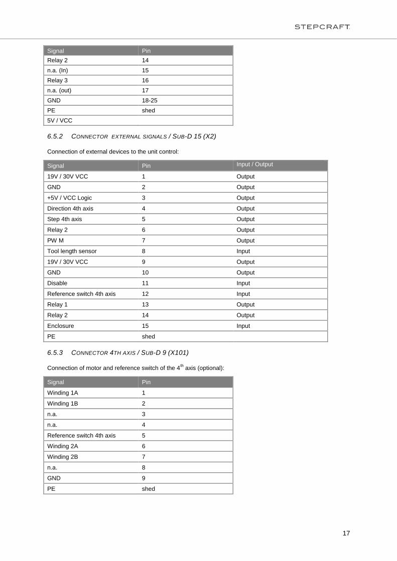
6.5.2 CONNECTOR EXTERNAL SIGNALS / SUB-D 15 (X2)
Connection of external devices to the unit control:
Signal Pin Input / Output
19V / 30V VCC 1 Output
GND 2 Output
+5V / VCC Logic 3 Output
Direction 4th axis 4 Output
Step 4th axis 5 Output
Relay 2 6 Output
PW M 7 Output
Tool length sensor 8 Input
19V / 30V VCC 9 Output
GND 10 Output
Disable 11 Input
Reference switch 4th axis 12 Input
Relay 1 13 Output
Relay 2 14 Output
Enclosure 15 Input
PE shed
6.5.3 CONNECTOR 4TH AXIS / SUB-D 9 (X101)
Connection of motor and reference switch of the 4th axis (optional):
Signal Pin
Winding 1A 1
Winding 1B 2
n.a. 3
n.a. 4
Reference switch 4th axis 5
Winding 2A 6
Winding 2B 7
n.a. 8
GND 9
PE shed

18
7 TRANSPORTATION / STORAGE
7.1 TRANSPORTATION
NOTICE: Please observe that the machine is very heavy and bulky when transporting it.
If necessary transport the machine with the help of a second person.
Please only use suitable transportation vehicles and carriers for transportation.
WARNING: Never lift heavy loads above people!
7.2 PACKAGING
When you do not want to reuse the packaging material of the machine and of its components please separate it
according to the disposal conditions on site and take it to a collection center for recycling or dispose of it.
7.3 STORAGE
If the machine or its components is not used for a longer time please note the following for the storage:
- Store the machine and the components only in closed rooms
- Protect it against humidity, wetness, cold, heat and direct sun radiation
- Store it dust-free, cover it, if required
- The storage place must not be subject to vibrations
8 MAINTENANCE
8.1 SAFETY
WARNING: Before performing maintenance works on the machine switch it off and secure it against
unintended restarting by disconnecting the mains switch of the controller!
WARNING: Before you use a system-guided tool with its own mains plug disconnect it also!
NOTICE: All maintenance works must only be performed by a technically experienced person.
WARNING: In case of improper handling of the machine there is a high risk of injury!
8.2 MAINTENANCE WORKS
NOTICE: Always thoroughly handle your STEPCRAFT in order to enjoy working with it for a long time. Regular
maintenance crucially influences the service life of your machine.
Therefore please perform the following maintenance:

19
Lubrication of linear tracks and lead screws must be carried out with supplied grease from STEPCRAFT: Klüber
Microlube GL 261 or other with similar specifications.
Apply grease on positions marked as mentioned:
1. All guide areas have to be adequately greased before the machine can be put into service
2. After 20 operating hours wipe the guide area clean and apply grease again
3. Repeat step 2 if soiled but latest every 20 hours.
Also always keep the machine clean. Any accruing chips or other soiling should be sucked off or thrown away
after each working step. Furthermore, please make sure that no chips or similar means get caught in the mobile
parts.

20
9 MALFUNCTIONS
9.1 BEHAVIOR IN CASE OF MALFUNCTIONS
CAUTION: If a malfunction occurs on the system which might cause person or material damages please
immediately stop the working process by pressing the emergency-stop switch!
In case of slight malfunctions please stop the machine as usual using the control.
If you are not able to remedy the malfunction yourself please contact us by indicating the malfunction which
occurred. Please find our contact data on item 10.3 of these instructions.
10 ANNEX
10.1 WARRANTY AND SERVICE CONTACT INFORMATION
Country of Purchase STEPCRAFT Address Phone No. / Email
Address
United States of America STEPCRAFT Inc. 733 E Main St. Unit 3
Torrington, CT, 06790
+1 203 556 1856
Germany STEPCRAFT GmbH &
Co. KG
An der Beile 2
58708 Menden
Germany
+49 2373 179 1160
info@stepcraft-
systems.com
Rest of World Local distributor
STEPCRAFT GmbH &
Co. KG
see https://www.stepcraft-
systems.com/en/retail
An der Beile 2
58708 Menden
Germany
see https://www.stepcraft-
systems.com/en/retail
+49 2373 179 1160
info@stepcraft-
systems.com
10.2 MANUFACTURER
STEPCRAFT GmbH & Co. KG
An der Beile 2
58708 Menden
Germany
Phone: +49 (0) 2373 –179 11 60
E-Mail: [email protected]
Website: www.stepcraft-systems.com
10.3 TYPE PLATE
The type plate is at the left side of the machine on the inspection flap.
Example:

21
10.4 COPYRIGHT
The contents of these operating instructions are the intellectual property of the company STEPCRAFT.
Forwarding or copying (also in excerpts) is not allowed unless we authorized it expressively in writing. Any
infringements are prosecuted.
10.5 LIMITED WARRANTY
What this Warranty Covers
STEPCRAFT GmbH & Co. KG (“STEPCRAFT”) warrants to the original purchaser that the product purchased
(the “Product”) will be free from defects in materials and workmanship at the date of purchase.
What is not covered
This warranty is not transferable and does not cover (i) cosmetic damage, (ii) damage due to acts of God,
accident, misuse, abuse, negligence, commercial use, or due to improper use, installation, operation or
maintenance, (iii) modification of or to any part of the Product, (iv) attempted service by anyone other than a
STEPCRAFT authorized service center, (v) Product not purchased from an authorized STEPCRAFT dealer, or
(vi) Product not compliant with applicable technical regulations.
OTHER THAN THE EXPRESS WARRANTY ABOVE, STEPCRAFT MAKES NO OTHER WARRANTY OR
REPRESENTATION, AND HEREBY DISCLAIMS ANY AND IMPLIED WARRANTIES, INCLUDING, WITHOUT
LIMITATION, THE IMPLIED WARRANTIES OF NON-INFRINGEMENT, MERCHANTABILITY AND FITNESS
FOR A PARICULAR PURPOSE. THE PURCHASER ACKNOWLEDGES THAT THEY ALONE HAVE
DETERMINED THAT THE PRODUCT WILL SUITABLY MEET THE REQUIREMENTS OF THE PURCHASER`S
INTENDED USE.
Purchaser´s Remedy
STEPCRAFT´s sole obligation and purchaser´s sole and exclusive remedy shall be that STEPCRAFT will, at its
option, either (i) service, or (ii) replace, any product determined by STEPCRAFT to be defective. STEPCRAFT
reserves the right to inspect any and all product(s) involved in a warranty claim.
SERVICE OR REPLACMENT AS PROVIDED UNDER THIS WARRANTY IS THE PURCHASER´S SOLE AND
EXCLUSIVE REMEDY.
Limitation of Liability
STEPCRAFT SHALL NOT BE LIABLE FOR SPECIAL, INCIDENTAL OR CONSEQUENTIAL DAMAGES, LOSS
OF PROFITIS OR PRODUCTION OR COMMERCIAL LOSS IN ANY WAY, REGARDLESS OF WHETHER
SUCH CLAIM IS BASED IN CONTRACT, WARRANTY, TORT, NEGLGENCE, STRICT LIABILITY OR ANY
OTHER THEORY OF LIABILITY, EVEN IF STEPCRAFT HAS BEEN ADVISED OT THE POSSIBILITY OF SUCH
DAMAGES. Further, in no event shall the liability of STEPCRAFT exceed the individual price of the product on
which liability is asserted. As STEPCRAFT gas no control over use, setup, final assembly, modification or misuse,
no liability shall be assumed nor accepted for any resulting damage or injury. By the act of use, setup or
assembly, the user accepts all resulting liability. If you as the purchaser is advises to return the product
immediately in new and unused condition to the place of purchase.
Law
These terms are governed by German law (without regard to conflict of law principals).
This warranty gives you specific legal right, and you may also have other rights. STEPCRAFT reserves the right
to change or modify this warranty at any time without notice.
Warranty Services
Questions, Assistance, and Service
Your local STEPCRAFT store and/or place of purchase cannot provide warranty support or service. Once
assembly, setup or use of the products has been started, you must contact your local distributor or STEPCRAFT
directly. This will enable STEPCRAFT to better answer your question and services you in the event that you may
need any assistance. For questions or assistance, please visit our website or call to speak to a product support
representative (see item 10.1).

22
Inspection or Services
If this Product needs to be inspected or serviced and is compliant in the country you live and use the product in,
please use the STEPCRAFT online service request submission process found on our website or call
STEPCRAFT. Pack the product securely using a shipping carton. Please note that original boxes may be
included, but are no designed to withstand the rigors of shipping without additional protection. Ship via a carrier
that provides tracking and insurance for lost or damaged parcels, as STEPCRAFT is not responsible for
merchandise unit it arrives and is accepted at our facility. When calling STEPCRAFT, you will be asked to provide
your complete name, street address, email address and phone number where you can be reached during
business hours. When sending product into STEPCRAFT, please include your contact details and a list of the
included items, and a brief summary of the problem. A copy of your original sales receipt must be included for
warranty consideration. Be sure your name and address are clearly written on the outside of the shipping carton.
Warranty Requirements
For Warranty consideration, you must include your original sales receipt verifying the proof-of-purchase date.
Provide warranty conditions have been met, your product will be serviced or replaced free of charge. Service or
replacement decisions are at the sole discretion of STEPCRAFT.
NON-Warranty Service
Should your service not be covered by warranty, service will be completed and payment will be required without
notification or estimate of the expense unless the expense exceeds 50% of the retail purchase cost. Provided
warranty conditions have been met, your product will be serviced or replaced free of charge. Service or
replacement decisions are at the sole discretion of STEPCRAFT.
Non-Warranty Service
Should your service not be covered by warranty, service will be completed and payment will be required without
notification or estimate of the expense unless the expense exceeds 50% of the retail purchase cost. By submitting
the item for service you are agreeing to payment of the service without notification. Service estimates are
available upon request. You must include this request with your items submitted for service. Non-warranty service
estimates will be billed a minimum of ½ hour of labor. In addition you will be billed for return freight. STEPCRAFT
accepts money orders cashier´s checks, as well as credit cards and PayPal payment. By submitting any item to
STEPCRAFT for service, you are agreeing to STEPCRAFT`s Terms and Conditions found on our website (see
item 10.1).
ATTENTION: STEPCRAFT service is limited to product compliant in the country of use and ownership. If
received, a non-compliant product will not be serviced. Further, the sender will be responsible for arranging return
shipment of the un-serviced Product, through a carrier of the sender´s choice and at the sender´s expense.
STEPCRAFT will hold non-compliant product for a period of 60 days from notification, after which it will be
discarded.
10.6 INSTRUCTIONS FOR DISPOSAL OF WEEE BY USERS OF THE EUROPEAN UNION
This product must not be disposed of with other waste. Instead, it´s the user´s responsibility to dispose of their waste equipment by handing it over to a designated collections point for he recycling of waste electrical and electronic equipment. The separate collection and recycling of your waste equipment at the time of disposal will help to conserve natural resources and ensures that it is recycled in a manner that protects human health and the environment. For more information about where you can drop off your waste equipment for recycling, please contact your local office, your house-hold waste disposal or where you purchased your product.
10.7 ROHS, 2002/95/EG
We confirm that the machines of the STEPCRAFT series comply with the RoHS, 2002/95/EC

23
10.8 EC-DECLARATION OF CONFORMITY

24
Copyright ©
STEPCRAFTTM