operating instructions - spartan controls/media/resources/ecom/u/15_ecom_en2... · ecom-en2 page 3...
TRANSCRIPT

Operating Instructions
Creative technology made by rbr

Page 2 ecom-EN2
Index Page
Important Hints 31. Instrument Design 42. Accessories ecom-EN2 53. Gas Cooler (option) / Model version ecom-EN2-P 64. Power Supply 75. Data Memory 76. Instrument Start 87. Input or Selection of combustion plants 108. Flue Gas Analysis
8.1. Gas analysis 138.2. CO measurement (gas path check) 168.3. O2 check 178.4. Draught measurement 178.5. Flow measurement (option) 188.6. Soot dot...Oil trace 198.7. Measurement record and printout 20
9. Mean Value Measurement (option) 2110. Adjustements 2311. Control 2712. Data Processing 2813. Diagnostics
13.1. Fault diagnostic 30 13.2. delta-T measurement 32 13.3. Heating check (option) 32 13.4. 4 Pa measurement (option) 36
14. Maintenance Tips 3715. Technical Data 40
ecom-EN2 Page 3
Important Hints
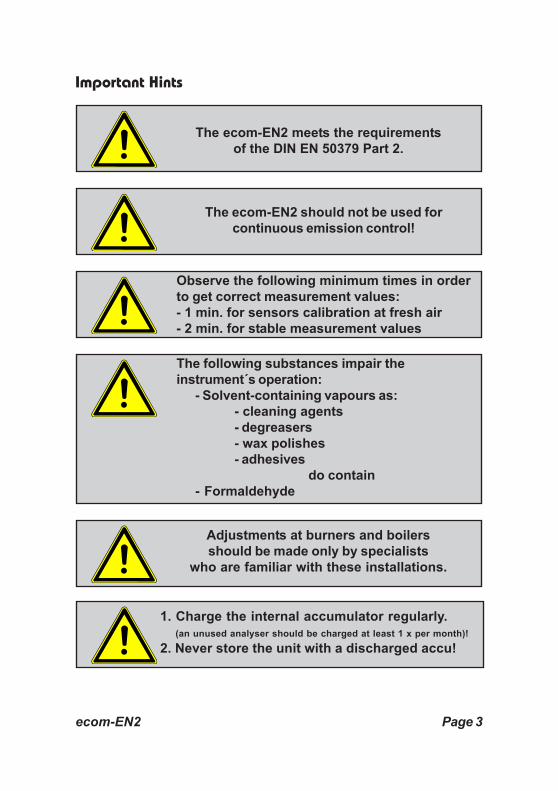
The ecom-EN2 should not be used forcontinuous emission control!
The ecom-EN2 meets the requirementsof the DIN EN 50379 Part 2.
Observe the following minimum times in orderto get correct measurement values:- 1 min. for sensors calibration at fresh air- 2 min. for stable measurement values
Adjustments at burners and boilersshould be made only by specialists
who are familiar with these installations.
The following substances impair theinstrument´s operation:
- Solvent-containing vapours as:- cleaning agents- degreasers- wax polishes- adhesives
do contain- Formaldehyde
1. Charge the internal accumulator regularly. (an unused analyser should be charged at least 1 x per month)!2. Never store the unit with a discharged accu!
Page 4 ecom-EN2
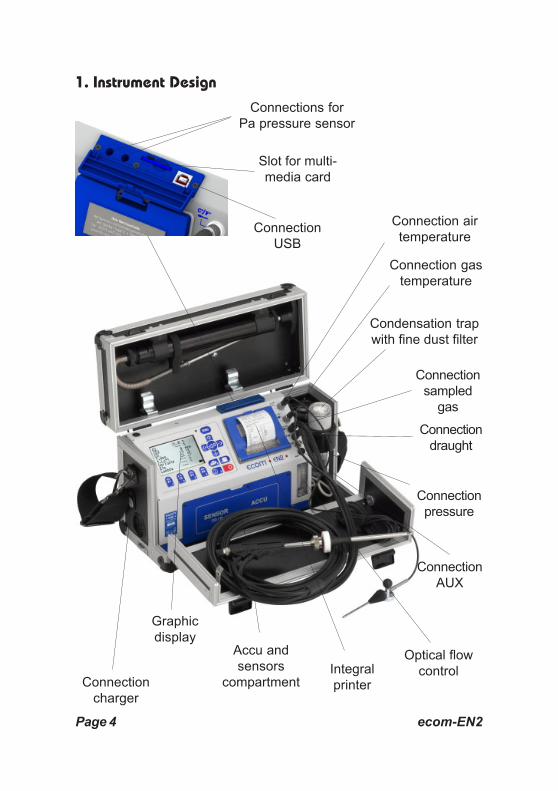
Connectionsampled
gas
Condensation trapwith fine dust filter
Optical flowcontrolIntegral
printerConnectioncharger
1. Instrument Design
ConnectionUSB
Connection gastemperature
Connection airtemperature
Connectiondraught
Connectionpressure
Accu andsensors
compartment
Slot for multi-media card
Graphicdisplay
ConnectionAUX
Connections forPa pressure sensor

ecom-EN2 Page 5
Function keys(function shown on
display)
Print key(access to
printing menu)
Enter key(confirm
selection)
ESC key(quit/
escape menu)
Cursor keys(Up/Down/Right/
Left/Scroll)
Keyboard
Valuesrecording
ON / OFFkey
Info key(access to
controlmenu)
In the input mode, the keys areused for numerical inputs
2. Accessories ecom-EN2
T-Room stickItem no.:51446
Multi-media card128 MBItem no.:53656
Filtering case forsolid fuel typesmeasurementsItem no.:55810
Filtering plate forsolid fuel typesmeasurementsItem no.:50000024

Page 6 ecom-EN2
Gas inlet
Gasoutlet
Fan
Peltierelement
Levelmonitoring
Condensateevacuation
3. Gas Cooler (option) / Model version ecom-EN2-P
Exhaust gas with a temperature over the steam dew point (35 - 65 °C) isflown spiral via a long gas path thru a surface coated metal body withgood thermal conductivity. The gas radiates its heat to this metal body.A Peltier element (semi-conductor cooling element) flown by a continuouscurrent is thermically connected with this body and with a second metalbody with cooling ribs and ventilation slots.The flow thru the Peltier element creates a heat transfer from WARM toCOLD, drains the heat of the metal body flown by gas and conveys it tothe outer cooling body. This heat is conveyed thru a vertical forcedventilation to the surrounding air.The condensation issued by the heat loss of the gas drops in a receptacleand is pumped out on request by a pediodically working hose pump.
By accumulator operation, the Peltier cooler can be switched off.In the measurement menu press hereto <Enter>, select the menu point„Peltier I/0“ and press again <Enter> (for Peltier cooler switch on, justrepeat this procedure).
The power needs of the gas cooler being high,the cooling performance shall be reduced
by accumulator operation!

ecom-EN2 Page 7
4. Power Supply
The ecom-EN2 comes with an external charger. The analyser canalso be powered via the internal accumulator for a while (6 V; 3.8 Ah).The accumulator recharge should be started when the instrumentrequires to (acoustical warning and display indication). Theaccumulator charging stand can be checked looking at the voltageindication on the display (menu "Control" - Info key). The accu warningis activated when the value „Accu“ is smaller than 5.7 V.By 5.4 V the power operation via accu is no more possible; the instrumentmust be further powered via the external charger.
5. Data Memory
The multi-media card enables the storage of punctual measurements;the gathered values are written in a text file (J2KDV.txt). Data formatinformation is to be found in the appendix. The files can be transferredto a PC via a card reader.The following conditions must be fulfilled for using a multi-media card:
- minimal card volume 32 MB - max. 2 GB- card formatted on 16 bit FAT- SD or MM card from rbr- PC with card reader from rbr
- or from the manufacturers Belkin and SanDisk
Used accumulators can either be returnedto us or brought to recycling stations of
public waste disposal companiesrespectively to stores selling accumulators!
Page 8 ecom-EN2
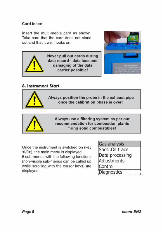
Card insert
Insert the multi-media card as shown.Take care that the card does not standout and that it well hooks on.
6. Instrument Start
Once the instrument is switched on (key<I/0>), the main menu is displayed.6 sub-menus with the following functions(non-visible sub-menus can be called upwhile scrolling with the cursor keys) aredisplayed:
Never pull out cards duringdata record - data loss and
damaging of the datacarrier possible!
Always position the probe in the exhaust pipeonce the calibration phase is over!
Always use a filtering system as per ourrecommendation for combustion plants
firing solid combustibles!
Gas analysisSoot..Oil traceData processingAdjustmentsControlDiagnostics

ecom-EN2 Page 9
- Gas analysis : Perform gas analysis- Soot...Oil trace : Input of soot measurement results- Data processing : Assign measurements / Data transfer
(only by inserted MM card)- Adjustments : Modify instrument adjustements- Control : Check operation state of instrument- Diagnostics : Read-out of firing automate
(only in connection with ecom-AK) / delta-T measurement / Heating check / 4 Pa test
To perform measurements, select with the cursor keys the sub-menu"Gas analysis" and confirm with <Enter>. The instruments starts thena 1- minute calibration phase and the fuel types selection list is displayed.The following fuel types are available:
Fuely types acc. to 1st BImSchV
Fuel oil (B)Natural gas (B)City gas (B)Coke oven gas (B)Liquid gas (B)
Use the cursor keys to select the desiredfuel type and confirm with <Enter>. Theinstrument will then enquire if you wish touse the data bank. If you want to assignthe sampled data to a specific plant, sopress <F1> (<F4> = no: measurement willbe performed without assignment).
CO2max A1 B15.4 0.50 0.007
Select: (↑↓ ↑↓ ↑↓ ↑↓ ↑↓ ↵↵↵↵↵) !
Fuel type
Fuel oil (B)
Do you wish touse the dataprocessing?Select : <↵↵↵↵↵> !
NOYES

Page 10 ecom-EN2
7. Input or selection of combustion plants
To call up plant data already recorded or to create a new file, the followingpossibilities are available:
Create new (is automatically selectedby first use of a MM card): To create anew file, a numerical number should beassigned.Select „Create new“ and confirm with<Enter>. Input a random number (max.16 figures) using the keyboard:- use the cursor keys <Up/Down/Right/Left> to select the figure (selected figure outlined by a black background)- press <Enter> to accept the figure (press <F2> to delete the last figure if needed)- repeat this procedure until the desired number is complete.
Example: "25.11.2008"
Tip: We suggest a date-related input to easily find the data record later on via the search function.
After confirming with <F1> it is possible to enter a text via the keyboard(max. 6 lines with 20 characters each) which is printed out and can beused for data processing purposes. Proceed as follows:- select text line 1 using the cursor keys <Up/Down> and confirm with <Enter>- select with <F3> the keyboard mode (4 keyboard modes are available)- select with the cursor keys <Up/Down/Right/Left> the desired character (selected character outlined by a black background)- press <Enter> to accept the character (press <F2> to delete the last character)- repeat this procedure until the desired text is complete.
Search wordRecord numberCreate new
Quit with: ESC
Selection upon:

ecom-EN2 Page 11
- proceed as follows to correct a character:- press <F4> to interrupt the character selection- use the cursor keys <Right/Left> to select the character requiring correction- activate with <F4> the character selection and correct character
- return with <F1> to character selection and call up next line for processThe input is closed with <ESC> and the next available data record isactivated. Press <ESC> to return to the gas analysis menu.
Record number: For check of the plantalready stored in the instrument, theselection upon record number is mostappropriate.
Select „Record number“ and confirmwith <Enter>. Input a random data recordnumber:
Example: "3" for data record number 3
- Press <Enter> once the input is completed to call up said data record number. The cursor keys <Up/Down> enable the check of the record numbers.- Press <F1> to select the first record number and <F2> for the last.- Press <F4> to delete the content of the selected record number.- Press <Enter> to activate the record number.- Finally press <ESC> to start the gas analysis.
Search wordRecord numberCreate new
Quit with:
Selection upon:
3
Please use thenumerical keys!
Input number

Page 12 ecom-EN2
Search word: If the plant code is known, it is possible to find the plantdata stored with help of a search machine.Select hereto "Search word" and confirm with <Enter>. Using thesoftware keyboard, input at least 3 connected figures of the plant:
Example: "25.11" for plant code 25.11.2008
After input completion, press <F1> to startthe search. All files matching this code willbe filtered. The resulting selection can bescrolled using the cursor keys (F1 forselection start, F2 for selection end). Oncefound, activate the desired data recordwith <Enter>. The last measurement onthis plant can be viewed pressing <Enter>/ „View memory“ / <Enter>. Allmeasured and calculated values can becalled up on 5 display pages, using thecursor keys to step thru.
Press <ESC> to escape the preceeding measurement data and therecording of the current data can start.
Measurement available
Record number 1
25.11.2008
Record number 1
25.11.2008
12:15:53 25.11.08
O2 3.2 %CO2 13.1 %CO 0 ppmEfficiency 92.5 %Losses 7.5 %Excess air 1.18T.Gas 184 °CT.Air 20 °C
Gas analysis 12:15:53 25.11.08Record number 1
O2 17.5 %
CO 0% 738 ppm
CO 123 ppm
Excess air 7.00CO measurement 12:15:53 25.11.08Record number 1
Oxygen check 12:15:53 25.11.08Record number 1
Oxygen test
O2 19.5 %
CO 3 ppm
Draught 00.1 hPa
T1 70.4 °C
T2 56.3 °C
dT 14.1 °C
delta-T measurement
delta T measurement 12:15:53 25.11.08Record number 1
Soot..Oil traceBoiler temp.: 65°C1.Soot meas. : 0.52.Soot meas. : 0.33.Soot meas. : 0.7Oil trace : NO
delta T measurement 12:15:53 25.11.08Record number 1

ecom-EN2 Page 13
8. Flue Gas Analysis
8.1. Gas analysis
After the 1-minute calibration phase, the instrument switches over tothe measurement mode. The gas measurement values can be viewedon 4 display pages. Use the cursor keys to scroll the pages.
Pressing <F1> enables to switch, from the values display, to a menupoint selected before or on „Standby“ (see chapter Adjustments).Possible menu points are: Soot...Oil trace, Data processing, Viewmemory, Display values, Fuel type, Efficiency (K), Internal,Adjustments. Furthermore you can switch back from any random menupoint to the values display with <F1>.Press <F2> to print out the values simultaneously to their recording inthe intermediate memory.Press <F3> to cut the CO sensor from the gas path so that it is protectedagainst too high concentrations.Pressing <F4> also enables to switch, from the values display, to amenu point selected before or on „Standby“ (see chapter Adjustments).Possible menu points are: Soot...Oil trace, Data processing, Viewmemory, Display values, Fuel type, Efficiency (K), Internal, Adjustments(back to values display with <F1>).
Switch-offCO sensorkey <F3>
Hotkeykey <F4>
Re-calibrate the instrument after eachmeasurement (after one hour at the latest)
to keep the accuracy of the results!
Store and printvalues
key <F2>
HotkeyKey <F1>
O2 3.2 %
CO2 13.1 %
T.Gas 184 °C
T.Air 20 °C
Gas analysis

Page 14 ecom-EN2
The position of the measured and calculated values (gas analysissub-menu) on the display pages is free selectable. For alteration ofthe existing succession, proceed as follows:
- Press <Enter> / „Display values“ / <Enter> to activate the function- select line with cursor keys (Up/Down)- select desired parameter with cursor keys (Right/Left)- repeat procedure until desired layout is completed
- Press <Enter> to deactivate the function
Connect the sampling tubing on the instrument to the plug „Connectiongas“. Position the sampling probe in the exhaust channel, so that thethermocouple is fully surrounded with the gas (see drawing).
Perform the measurement in the core stream of the exhaust gaschannel (probe placed in the hottest gas temperature area). A trendindication for T.Gas easies the core stream search. As long as the displayshows an arrow in upwards direction, the measured temperatureincreases, it means the probe tip moves towards the core streamcenter. If an arrow in downwards direction is displayed, it means youmove the probe away from the core stream and the temperature sinks.If no temperature change is shown for at least 3 seconds, so the trendindication will disappear.
Core stream search
O2 3.2 %CO2 13.1 %CO 0 ppmEfficiency 92.5 %Losses 7.5 %Excess air 1.18T.Gas 184 °CT.Air 20 °C
Gas analysis
Protection bowProbe tip
Gas stream

ecom-EN2 Page 15
CO2, efficiency, losses, excess air and dew point are calculated values.They can only be calculated if realistic values for the basic parameterslike O2 and the temperatures are available. It must be ascertainedthat:
O2 < 20,5 % and T.Gas - T.Air > + 5 °C
are given. The dew point can only be calculated accurately if, in themenu "Adjustments", the current barometric air pressure value hasbeen inputed. If the gas temperature falls below the dew point (between25 and 65 °C), so efficiency will be calculated with condensation gain.In this case a (K) is displayed after „Efficiency“.Correct measurement values are displayed first after a short delay,necessary for the gas transport and the build-up of a stableelectrochemical reaction to the sensors. This time period lasts approx.1 to 1.5 minute. For recording, printout and evaluation, wait until thevalues do not change anymore. If deviations higher than 2 ppm stilloccur by the gas values, they can be due to unstable pressure conditionsin the exhaust channel.
If the measurement values are stable andthe results can be printed out, press thekey <Record> (disk symbol) to transferthe values in the intermediate memory(caution: store separately gas analysis,CO, O2 check and draught measu-rements). They will be kept there for alater printout and, if need be, for a finaldata record storage.
If a printout of the values should be made simultaneously to theintermediate recording, so press <F2> (the complete content of theintermediate memory will be printed).
Measurement storedin intermediate
memory
O2 3.2 %CO2 13.1 %CO 0 ppmEfficiency 92.5 %Losses 7.5 %Excess air 1.18T.Gas 184 °CT.Air 20 °C
Gas analysis

Page 16 ecom-EN2
The CO sensor is protected against exceedings thanks to an internalprogramme. If the 4000 ppm limit value is exceeded, so a purgingpump is activated which provides the sensor with fresh air. After sufficientpurging time (X behinds CO disappears) the sensor can be reintegratedinto the measurement system with <F3> (if you choose „Yes“ at„Adjustments“ / „Internal“ / „CO-Automatic“ the CO sensor switchsto measurement automaticaly). The sensor can also be manually beexcluded from the measurement system with <F3>.
8.2. CO Measurement (gas path check)
The gas channel check, called also CO measurement, is used for thetechnical check of gas-fired plants in regards of safety aspects.Hereby the CO concentration in the gas channel is measured afterthe flow safety device and calculated on an undiluted value (oxygenrest content in flue gas = 0%). As the gas conditions after the flowsafety device are no more homogeneous because of the flow in ofsecundary air and consequently the core stream measurement can beerratic, the analysis of the exhaust gas is performed along the totality ofthe exhaust pipe diameter. A multi-hole probe (optional accessory) ishereby used as sampling probe.
The calculated value shown on the line „CO0 %“ corresponds to the measured COconcentration supposed the oxygencontent would amount 0% by the sameexhaust gas volume. It is consequentlythe undiluted CO content in exhaust gas.If the values indication is stable, press<Record> to store the result in theintermediate memory. If a printout of thevalues should occur simulataneously to therecording in the intermediate memorypress <F2> (the complete content of theintermediate memory will be printed out).
Measurement storedin intermediate
memory
O2 17.5 %
CO 0% 738 ppm
CO 123 ppm
Excess air 7.00CO measurement

ecom-EN2 Page 17
8.3. O2 check
This measurement is performed by room-independant plants like grosscalorific value plants. It is determined if exhaust gas flows into thecombustion air (O2 content drops down / CO content can be present)and herewith influence on the combustion quality.For this analysis, a special multi-hole pro-be (optional accessory) should be used.If the value indicated is stable, press<Record> to store the value in theintermediate memory. If a printout of thevalues should occur simultaneously to therecording in the intermediate memory,press <F2> (the complete content of theintermediate memory will be printed out).
8.4. Draught Measurement
A trend indication for the draught conditions in the exhaust channelcan already be viewed during the gas analysis. Nevertheless the valuefor the chimney draught will not be stored together with the gas valueswhile pressing <Record> because the differential pressure sensor tendsto drifts because of its sensibility.For an exact measurement, it is consequently advised to re-calibratethis sensor just before sampling and documenting the value.
The display shows the current value aswell as the recommendation to re-set thezero point of the sensor. Disconnect thedraught hose from the instrument for ashort moment and press <F4>. The sensoris herewith re-calibrated.
Measurement storedin intermediate
memory
O2 19.5 %
CO 3 ppm
Draught 0.01 hPa
Oxygen test
Oxygen test
Draught measurement
Recorded value: --.-- hPa
0.12 hPa

Page 18 ecom-EN2
Re-connect the draught tubing. Thedisplay shows the exact measurementvalue which can be stored while pressing<Record> and added to those resultsprevious stored in the intermediatememory. The stored value is shown onthe display. Press <ESC> to exit thedraught measurement menu.
8.5. Flow measurement (option)
This measurement can be done with a pitottube. At first the pitot factor of the pitot tubemust be entered („Adjustments“ /„Internal“ / „Pitot factor“). Afterconnecting the pitot tube to theinstrumentment, the zero point of thesensor can be set with <F4>. With <F1>the cross section of the flow channel canbe entered (needed for colculation of theflow rate). After the pitot tube iss positionedin the flow channel, the display shows thespeed (m/s) and the flow rate (Nm3/h). Ifthe value indicated is stable, press<Record> to store the value in theintermediate memory. If a printout of thevalues should occur simultaneously to therecording in the intermediate memory,press <F2> (the complete content of theintermediate memory will be printed out).
Measurement storedin intermediate
memory
Draught measurement
Recorded value: 0.12 hPa
0.12 hPa
Gas speed 0.3 m/sec
M.Flow 44 Nm3/h
Flow measurement
Gas analysis
Connections forpitot tube
Measurement storedin intermediate
memory

ecom-EN2 Page 19
8.6. Soot...Oil trace
The sub-menu "Soot...Oil trace" enablesthe input of measured results for boilertemperature, soot dots and oil trace.Select the desired line on the display andactivate the input with <Enter>. The inputfor boiler temperature and sootmeasurements 1-3 can be made one afterthe other with help of the instrumentkeyboard. Press <Enter> to store the valuein the data record of the measurement.
The result of the oil trace check will be documented as follows:
- Place cursor on line "Oil trace"- Consign the result with <Enter> ("No", "Yes" or "- - - ")
Once all inputs have been entered, press <ESC> to exit the menu. Themeasurement is now complete.
Soot..Oil traceBoiler temp. : 66°C1.Soot meas. : -.-2.Soot meas. : -.-3.Soot meas. : -.-Oil trace : ----
Select : ↑↓ ↵↵↵↵↵
Soot..Oil traceBoiler temp. : 66°C1.Soot meas. : 1.02.Soot meas. : 0.53.Soot meas. : 1.5Oil trace : NO
Select : ↑↓ ↵↵↵↵↵
Let the probe cool down before fixing it backin the fixation in the case cover!

Page 20 ecom-EN2
8.7. Measurement record and printout
Inportant: Once the gas analysis is completed, transfer the valuesrecorded in the intermediate memory on the MM card, otherwisethey would get lost by switch-off of the instrument!
Press <Print> (printer symbol) to enterthe printing menu. The sampled data canbe checked one more time („Viewmemory“, <Enter> and scroll with thecursor keys).
The software keyboard enables the inputor correction of the 6 lines text of the plantidentification. („Input text“, <Enter>, towrite text, see page 13).
All data correct? Then press „Memory -> M“ and <Enter> to transfer them in theinternal memory or on the MM card("Disk symbol" is shown in black in themeasurement mode). The inputed text istaken over into the data record only bytransfer on MM card.
Select („Start printout“ and <Enter>) toprint out the data.Press <ESC> to turn back to the gasanalysis mode.
The functions „View memory“,„Memory -> M“ and „Input text“ canalso be selected out of the measurementmode with <Enter>.
Start printoutView memoryMemory -> MInput textSelect : ↑↓ ↵↵↵↵↵
-- ECOM-EN2 --
Start printoutView memoryMemory -> MInput textSelect : ↑↓ ↵↵↵↵↵
-- ECOM-EN2 --
Start printoutView memoryMemory -> MInput textSelect : ↑↓ ↵↵↵↵↵
-- ECOM-EN2 --
Start printoutView memoryMemory -> MInput textSelect : ↑↓ ↵↵↵↵↵
-- ECOM-EN2 --

ecom-EN2 Page 21
9. Mean Value Measurement (option)
By mean value measurement function, measurements can be sampledwithin an adjustable time frame and mean values can be calculated.Should the single measurement values be stored, then a storage placemust be defined as described in chapter 7. Based on this storage place,all measurements will be written consecutively in the next storage places(observe storage capacity!).
Once the fresh air calibration iscompleted, select the menu point „Meanvalues“. Before starting, the parameters„Measurement time“, „Scanning“,„Printer“ and „Record“ should bechecked or modified if need be.The meaning is respectively:
- Measurement time = Time frame during which the mean values will be sampled- Scanning = Time interval between the measurements considered for mean value calculation- Printer = Documentation of measurements serving to the mean value calculation- Record = All measurements for mean value calculation will be stored
„Measurement time“ and „Scanning“ can be adjusted as follows:- select menu point and confirm with <Enter>- set the desired time using the numerical keys:
0.01 = 1 sec = minimal value59.59 = 59 min : 59 sec = maximal value
- confirm with <Enter>
The settings for „Printer“ can be changed as follows:- select menu point and confirm with <Enter>- select desired adjustment with cursor keys- confirm with <Enter>
Gas analysisSoot..Oil traceData processingAdjustmentsControlDiagnostics
Select : ↑↓ ↵↵↵↵↵
Mean valuesStart measurementMeasurement timeScanningPrinterRecord

Page 22 ecom-EN2
The setting for „Record“ can be changed as follows:- select menu point and confirm with <Enter>- activate memory function with <F1> or- deactivate it with <F4>
Activate „Start measurement“ / <Enter>to start the sampling of the data. On thedisplay the current measurement values(constantly updated with new values) areshown. Once the measurement time isover, a protocol with all mean values canbe printed (press <Print>).
O2 3.2 %CO2 13.1 %CO 0 ppmT.Gas 184 °CT.Air 20 °CEfficiency 92.5 %Excess air 1.18
Mean values

ecom-EN2 Page 23
10. Adjustments
Additionally to those ecom-EN2 functions described previously, variousadjustments can be made in the instrument.From the main menu, select the sub-menu "Adjustments" and confirmwith <Enter>.A selection of modifiable parameters,adjustable according to the application,is displayed.Place the cursor on the desired line andpress <Enter> to call up or modify theadjustment. The modifiable parametersare:
Unit (adjustment with cursor keys):- Calculation of gas concentrations in:
- ppm = volume concentration (parts per million)- mg/m3 = mass concentration per volume unit- mg/kWh (undiluted) = mass concentration per power unit- mg/MJ (undiluted) = mass concentration per power unit- ppm (undiluted) = volume concentration (parts per million)- mg/m3 (undiluted) = mass concentration per volume unit
Undiluted:Conversion of the gas concentration on selected reference oxygen:
- mg/kWh and mg/MJ are always calculated on 0% O2 basis
- Conversion formula
O2 reference(for ppm und mg/m3 - Input after pressing <Enter>):
- Input of O2 reference value O2 ref
Eref = Emeas *21 - O2 ref
21 - O2 meas
AdjustmentsUnitO2 referenceFuel typeAir pressure
Clock setPaper feedInternal
Select : ↑↓ ↵↵↵↵↵

Page 24 ecom-EN2
Fuel type (press <Enter> to access selection list):- Modification of adjusted fuel type (e.g. by measurements at combi-plants)
Air pressure (press <Enter> to access menu):- Input of barometric air pressure for dew point calculation
Clock set (press <Enter> to access setting menu):- Correction of internal clock with cursor keys
Paper feed (press <Enter> to activate paper feeding):- Paper feed line by line

ecom-EN2 Page 25
Internal (press <Enter> to open menu):- Further instrument settings:
Printout contraste (0..9)(press <Enter> to access input menu):- Printer contraste adjustment
Display contraste(press <Enter> to access input menu):- Display contraste adjustment with cursor keys
Key beep(<F1> for YES / <F4> for NO):- Acoustical signal by key pressing
Language: English (change with <Enter>):- Info about selected language (3 languages selectable)
F1 Hotkey (selection after pressing <Enter>):- Modification of adjusted menu the programme will open after pressing <F1>
F4 Hotkey (selection after pressing <Enter>):- Modification of adjusted menu the programme will open after pressing <F4>
Efficiency (K) (<F1> for YES / <F4> for NO):- Efficiency calculation with or without condensation gain
USB (selection after pressing <Enter>):- Adjustment of transfer speed and protocol for the USB interface (connection USB) with the cursor keys
Bluetooth (selection after pressing <Enter>):- Adjustment of protocol for the Bluetooth interface with the cursor keys
Pitot factor (selection after pressing <Enter>):- Input of Pitot factor for flow rate calculation (standard = 0.93)
InternalPrintout contrasteDisplay contrasteKey beepLanguage: English
F1 HotkeyF4 HotkeyEfficiency (K)Baud ratePitot factorPrintout
Select : ↑↓ ↵↵↵↵↵

Page 26 ecom-EN2
Printout (selection after pressing <Enter>):- Text input for printout on measurement protocol (8 x 24 characters)- Input the text of line 1 as follows:1. Activate character selection list with <F4>.2. Select keyboard type with <F3> (4 different keyboards available).3. Use the cursor keys to select the desired character (selected character is outlined by black background).4. Confirm selection while pressing <Enter>.5. Repeat procedure until desired text is complete.6. Once input for line 1 is completed, deactivate the characters selection mode with <F4> and move to the second line with the cursor key <Down>.7. Once all lines have been processed as desired, exit the menu with <ESC>.
ecom-EN2 Page 27
11. Control
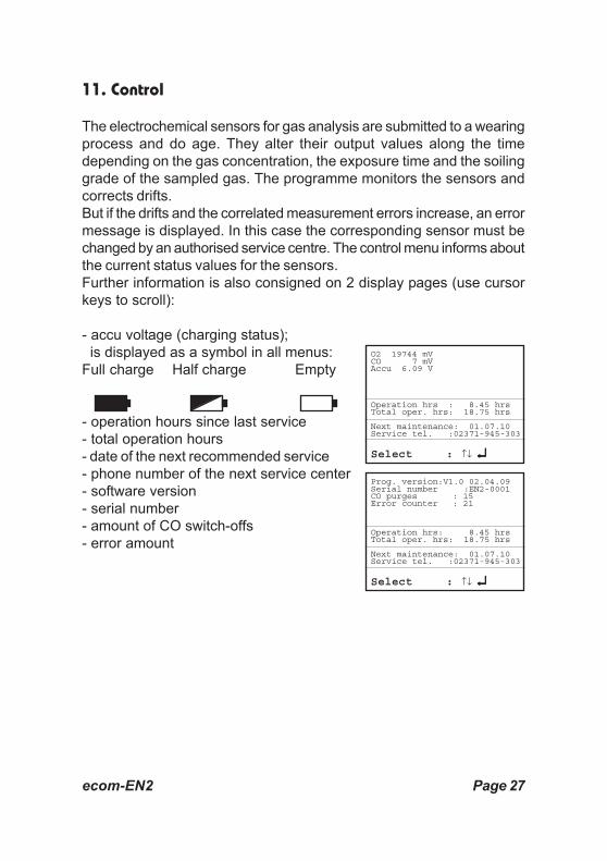
The electrochemical sensors for gas analysis are submitted to a wearingprocess and do age. They alter their output values along the timedepending on the gas concentration, the exposure time and the soilinggrade of the sampled gas. The programme monitors the sensors andcorrects drifts.But if the drifts and the correlated measurement errors increase, an errormessage is displayed. In this case the corresponding sensor must bechanged by an authorised service centre. The control menu informs aboutthe current status values for the sensors.Further information is also consigned on 2 display pages (use cursorkeys to scroll):
- accu voltage (charging status); is displayed as a symbol in all menus:Full charge Half charge Empty
- operation hours since last service- total operation hours- date of the next recommended service- phone number of the next service center- software version- serial number- amount of CO switch-offs- error amount
O2 19744 mVCO 7 mVAccu 6.09 V
Operation hrs : 8.45 hrsTotal oper. hrs: 18.75 hrs
Next maintenance: 01.07.10Service tel. :02371-945-303
Select : ↑↓ ↵↵↵↵↵
Prog. version:V1.0 02.04.09Serial number :EN2-0001CO purges : 15Error counter : 21
Operation hrs: 8.45 hrsTotal oper. hrs: 18.75 hrs
Next maintenance: 01.07.10Service tel. :02371-945-303
Select : ↑↓ ↵↵↵↵↵

Page 28 ecom-EN2
12. Data Processing
If a MM card is inserted in the slot, so itwill be used as record medium. The menu„Data processing“ offers the followingfunctions:
Select:For search or creation of plant files in the scope of assigningmeasurement values (see § 7.).
View:Recorded values of the selected plant can be viewed (see § 7.).
Memory (M):Here all stored measurements (sorted byrecord number) can be viewed. Singlemeasurement results can be called up asfollows:
- Select desired record number with the cursor keys and confirm with <Enter>- Scroll with the cursor keys- Press <ESC> to exit
Format:This function is usually needed by initial adjustment of the instrumentat our factory (preparation of MM card for data recording).Caution: All stored values will be cancelled!
Quit with: ESC
Data processingSelectViewMemory (M)Format
Date Fuel type 1 01.09.06 11:01 Fuel oil 2 01.09.06 11:02 Fuel oil 3 01.09.06 11:04 Fuel oil 4 01.09.06 11:07 Fuel oil 5 01.09.06 11:11 Fuel oil 6 01.09.06 11:23 Fuel oil 7 01.09.06 11:44 Fuel oil 8 01.09.06 11:53 Fuel oil
Select : ↑↓ ↵↵↵↵↵

ecom-EN2 Page 29
RDT <-> PC !:
Load data:Enables the data import from e.g. rbr software (available on our website„www.rbr.de“). See chapter „Technical Data“ for data format information(please observe the transfer options of your software!).
Proceed as follows:-Connect ecom-J2KN and PC via USB cable.-Select “Load data“ and confirm with <Enter>.-Answer the displayed question with YES (<F1>).-Decide if the data recorded can be cancelled (<F1> for YES / <F4> for NO).-Start the data transfer on your PC.
Send data:With this function the data records completed with measurement valuescan be transferred to the PC programme (procedure similar to chapter„Load data“).
Data logger:Here a Data logger record (“Data logger” and key <OK> / on top righton the display appears the disk symbol) can be started or finished (justavailable when using the multi media card). For each recording one filewill be written on the card. The files will be numbered consecutively (J2KDL-00.csv, J2KDL-01.csv and so on) and can be transferred to PC with acard reader. The length of a dataset is 500 byte which means that on a32 MB card 64000 measurements could be recorded.In addition to data logger recordings the data could be transferred online(with USB cable at 1200 Baud / Protocol DAS) to the software “DASNT”.The software is available free of charge from the rbr website.
Save to MMC (min. 1 second / max. 255 seconds):Adjustment of the interval time for data logger recordings.

Page 30 ecom-EN2
13. Diagnostics
13.1. Fault diagnostic
The ecom-EN2 is able to receive and toprocess information provided via cabletransfer by the ecom-AK (read-out headfor digital firing automates).Out of the main menu, select the sub-menu"Fault diagnostic" and confirm with<Enter>. The ecom-EN2 tries to establisha connection with the ecom-AK (displaymessage: „Search in process“). Bysuccessful attempt, the current burneroperation stand is displayed as a graphicon the display. The operation stand canbe recorded (max. 120 sec). Press<Enter> to initiate a new recording (reset).
Currentflame signal
Min. flamesignal
ecom-AK
Flameidentified
Engine on
Oil pre-warmer /Air pressuremonitor is on
Valve 1 is on
Ignition isactive
Valve 2 is on
Model name Recording of operationstand (max. 100 sec.):
1/0 = Continuous phaseGM = Fan motorHZ = Oil preheaterZT = IgnitionBV1 = Valve 1st stageBV2 = Valve 2nd stageFla = Flame identifiedStö = Disturbance
Reset = Starts a newrecording (confirm with<Enter>)
Operationvoltage
Cable connection toAUX connector
DKO 972 / 222.3 1.2
228AUSAUS
1/0GMHZZTBV1BV2FlaStö

ecom-EN2 Page 31
Use the cursor keys (Up/Down) to call up further data of the firingautomate. On the 2nd display page the current error and the number ofburner starts are displayed.
Ther 3rd display lists information about error history (type and volumeof information dependind on firing automat).
The 4th display page lists information about the monitoring times (typeand volume of information depending on firing automate).
Number of burnerstarts at a total resp.since reset of firingautomate
Error statistics(number oferrors)
Last 2 errors (Satronic)Last 5 errors (Siemens)(Scroll errors using<Right/Left>)
Current error
Monitoring times offiring automate
Number of startups total 677Service counter actual 142
Further pages: ↑↓
No error!Current error
Total : 46Straylight : 22Safety time : 9Loss of flame : 17FT/LW : 0
Flame signal duringstraylight check
Error history
After: 001 12 secStat : 2.2 µA 225 V
Select: ↑↓ <>
Timing valuesSafety time (TSA) 4.9 secDelay time valve 2 40.0 secPre-ignition time 17.0 secPost-ignition time 20.0 secDelay straylight sup. 11.5 secStraylight supervision 5.0 secRest time TSA (actual) 4.1 sec
Select: ↑↓

Page 32 ecom-EN2
13.2. delta-T Measurement
With the ecom-EN2 a difference temperature measurement is possible.For measurements at pipings (e.g water-in and water-out of heatingsystems), special temperature sensors are needed, available from yourauthorised rbr agency. Out of the main menu point "Diagnostics" selectthe sub-menu "delta-T measurement" and confirm with <Enter>.The instrument indicates the temperatureT1 (sensor at connection „Gastemperature“), the temperature T2(sensor at connection „Air temperature“)and the difference between bothtemperatures (T1 - T2). Press <Memory>to store the result in the intermediatememory. A printout can be started with<Print>.
13.3. Heating Check (option)
The heating check is a simple, expressive process to evaluate a completeheating plant (heat production, distribution and transfer) from the energeticpoint of view.Hereby the single plant components get inspected by the heating engineerin a combination of measurements and visual assessment and valued inregards of their energetic quality acc. to a negative point system ofmaximum 100 points.The higher the score, the farer the current plant is away from thedesirable energetic stand and the higher the energy saving potential wouldbe if modernisation measures are conducted.In combination with the special probesrequired hereto, the ecom-EN2 is able toperform the measurement of the heatingcheck parameters: gas losses, ventilationlosses and surface losses.Out of the main menu point "Diagnostics",select the sub-menu "Heating Check"and confirm with <Enter>.
Measurement stored inintermediate memory
T1 70.4 °C
T2 56.3 °C
dT 14.1 °C
delta T Messung
Select : ↑↓ ↵↵↵↵↵
Heating CheckGas lossesSurface lossesVentilation lossesResultsDelete

ecom-EN2 Page 33
The gas losses measurement is to beperformed with the instrument´s samplingprobe in the gas core stream after menucall up (see chapter 8.1.). Once themeasurement is recorded with<Memory> (disk symbol) the conversionof the measurement results in negativepoints is available under the menu point„Results“.
The surface losses measurement isperformed by a temperature sensor specificfor surfaces. The temperature differencebetween boiler surface and roomtemperature (air temperature sensor) isdetermined and the percentual loss iscalculated. Once the menu point is calledup, the boiler performance must be inputed.To easy the measurement width, depth andheight of the boiler can also be entered(dimensions will be memorized for surfacecalculation). Please proceed as follows:
- activate respective input window with <Enter>- inputs values using the keys numerical function- confirm input with <Enter>
or:- adjust values using the cursor keys <Right/Left>
If no boiler dimensions are inputed, press <F1> (Start) to activate themeasurement recording. Here the dimensions for all surfaces must beinputed.
Measurement stored inintermediate memory
O2 3.2 %CO2 13.1 %CO 0 ppmEfficiency 92.5 %Losses 7.5 %Excess air 1.18T.Gas 184 °CT.Air 20 °C
Gas analysis
Temperature sensorfor surfaces
Surface loss Boiler P 24.5 kW Width 1.20 m Height 1.20 m Depth 1.20 m
Start
Modify : ↑↓ ↵↵↵↵↵Start +

Page 34 ecom-EN2
Press <F3> (Start + ->) to start the realmeasurement. Proceed as follows:
- select surface (boiler side) to be measured with <F1> or <F2>- position surface sensor- record temperature difference with <Memory> - up to 10 values can be recorded per surface out of which a mean value will be calculated automatically- if need be, cancel measurements with <F4>- repeat this procedure for each surface
Once all surface temperatures have been determined, quit the menu with<ESC>. The surface losses get automatically calculated. The valueconversion in negative points is available in the menu point „Results“.
The ventilation loss measurement isperformed by a flow probe 30 sec. afterburner switch-off. This measurement canbe performed at the earliest 5 min. afterinstrument´s switch-on as the pressuresensor requires this period of time forstabilisation. Once the menu is called up,the values for air pressure, externaltemperature, boiler performance andexhaust gas pipe diameter must beinputed . Hereto proceed as follows:
- open respective window with <Enter>- input figures using numerical function of keys- confirm input with <Enter>
or:- adjust values using the cursor keys <Right/Left>
Surface loss Br. 1.20 m Hö. 1.20 m A 1.44 m2 T.O. 40.5 °C T.R. 21.5 °C T.O. 42.5 °C T.R. 21.5 °C
-1-
Surface Record
Surface loss Wi. --- m He. --- m A --- m2 T.S. --- °C T.A. --- °C T.S. 21.5 °C T.A. 21.5 °C
-0-
Surface Record
Flow probe

ecom-EN2 Page 35
Quit with: ESC
Heating CheckGas losses 2.9 %Points 2.6Surface loss 2.29 %Points 3.4Ventil. loss 3.11 %Points 3.0
Press <F1> (Start) prior to going thru the following steps to start themeasurement:
- release tubing of the flow probe- wait for zeroing of pressure sensor- re-connect tubing of the flow probe- position flow probe into exhaust gas pipe (observe mark for flow direction)- switch off burner and simultaneously press <F1>
or:- press <F2> to activate timer (5 sec.) and switch off burner by beep- after approx. 30 sec. the measurement value converted in negative points is available
An overview of the measurements is available under „Results“. Press<Print> to print them out.
Select : ↑↓ ↵↵↵↵↵
Heating CheckGas losses √Surface loss √Ventilation loss √ResultsDelete

Page 36 ecom-EN2
13.2. 4 Pa Measurement (option)
The simultaneous operation of room-dependent firing place and airevacuation system can lead to dangerous low pressure conditions.With the ecom-EN2 it is possible to check the low pressure limit value of4 Pa and to document in a diagramme the time course of the low pressurevalue. Once the menu point is called up, the measurement is to beperformed as follows:
- connect capillary hose for room where burner is installed to „+“- connect capillary hose for reference place (staircase or outside air to „-“- operate firing and evacuation systems with maximal performance- open window resp. connection door to burner room and check the correct evacuation of the exhaust gases- zero pressure sensor with <F4>- position capillary hose for reference location- start record pressure value course with <F1> (Start) (an acoustical signal is issued every 30 sec. which can be deactivated / re-activated pressing <F2>)- record pressure by opened window resp. connection door- close window resp. connection door after approx. 30 sec. and check low pressure- after approx. 30 sec. open window resp. connection door and check zero point- close window resp. connection after approx. 30 sec. and check low pressure- after approx. 30 sec. re-open window or connection door and check zero point- after approx. 30 sec. close window resp. connection door and check low pressure
Once the measurement time is completed, the diagramme can be viewedon the display (use <F3> to emphasize illustration 1x, 2x, 4x, 8x timesor A for automatic). Start a printout if needed with <Print>.
ecom-EN2 Page 37
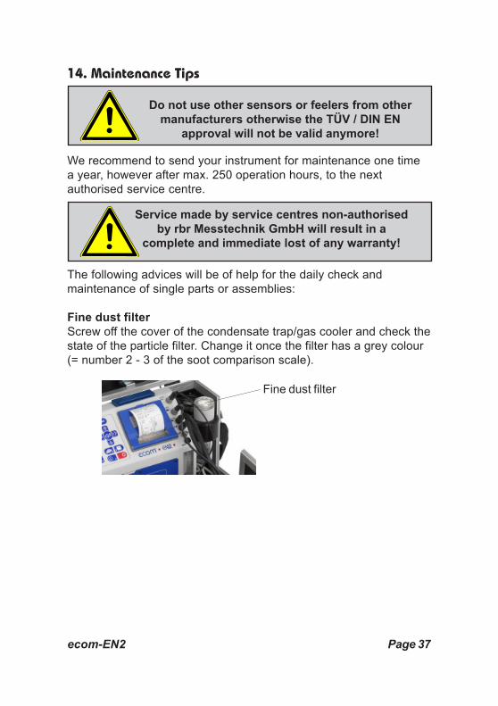
14. Maintenance Tips
We recommend to send your instrument for maintenance one timea year, however after max. 250 operation hours, to the nextauthorised service centre.
The following advices will be of help for the daily check andmaintenance of single parts or assemblies:
Fine dust filterScrew off the cover of the condensate trap/gas cooler and check thestate of the particle filter. Change it once the filter has a grey colour(= number 2 - 3 of the soot comparison scale).
Fine dust filter
Service made by service centres non-authorisedby rbr Messtechnik GmbH will result in a
complete and immediate lost of any warranty!
Do not use other sensors or feelers from othermanufacturers otherwise the TÜV / DIN EN
approval will not be valid anymore!

Page 38 ecom-EN2
PrefilterThe prefilter made of high-grade steel is within the condensate container.It should be cleaned when contamination (with warm water and dry).Unscrew condensate container and prefilter. Assemble after cleaningagain in reverse order.
SensorsThe sensors get calibrated with the reference gas fresh air by eachswitch-on. Their state is permanently checked by the instrument. Newsensors age along the operation time because of the wearing of thereagents (oxygen sensor) and due to soiling respectively exceedingconcentrations beyond the nominal measurement range (toxic sensors).The output values of the sensors are (menu "Control"):
O2 approx. 20000 mVOthers 0 mV (+/- 150)
If an error message is displayed during calibration and cannot beeliminated despite several calibration phases, so the instrument mustbe checked by a qualified and authorised service centre. The oxygensensor must show a value of >7000 mV, otherwise it must be changedby an authorised service centre.The CO sensor is protected against exceedings by the internalprogramme. If the limit value of 4000 ppm is exceeded, a second pumpswitches on and flows the sensor with fresh air. After sufficient purgingtime (X behinds CO disappears) the sensor can be reintegrated into themeasurement system with <F3> (if you choose „Yes“ at „Adjustments“/ „Internal“ / „CO-Automatic“ the CO sensor switchs to measurementautomaticaly). The sensor can also be manually be excluded from themeasurement system with <F3>.
Prefilter

ecom-EN2 Page 39
Probe and tubingDepending on the frequency of use, probe and tubing should be regularlycleaned in order to release particle deposits and to prevent early wearingdue to corrosion.- Release the connections at the instrument and at the probe grip to free the tubing.- Clean it (flow warm water in then dry respectively blow water drops out.- Slightly grease the O-rings of the tubing connections from time to time with acid-free grease.
Change printer paper roll- Release the printer cover (press lock downwards).- If necessary, extract the paper rest out of the printer. Hereto select "Adjustments"/"Paper feed"/<Enter>).- Remove the plastics tube of the previous roll.- Insert the paper end in the slot under the transport roll (paper roll inner side facing you while inserting the paper).- Convey approx. 3 cm paper thru the printer ("Adjustments"/"Paper feed"/<Enter>).- Lay the paper roll in the corresponding hollow.- Insert the paper thru the slot of the printer compartment cover and close the latest.
Lock printercover

Page 40 ecom-EN2
15. Technical Data
Parameter Range PrincipleO2 0 ... 21 vol-% ElectrochemistryCO 0 ... 4000 ppm ElectrochemistryNO (option) 0 ... 5000 ppm ElectrochemistryNO2 (option) 0 ... 1000 ppm ElectrochemistrySO2 (option) 0 ... 5000 ppm ElectrochemistryCO% (option) 4000 ... 63000 ppm ElectrochemistryCO2 0 ... CO2max CalculationT-Gas 0 ... 500 °C NiCr/NiT-Air 0 ... 99 °C Semi-conductor
Differential pressure 0 ... +/- 100 hPa DMS bridgeEfficiency 0 ... 120 % CalculationLosses 0 ... 99,9 % CalculationExcess air 1 ... ∞ CalculationCO undiluted (adjustable ref. O2) CalculatedFlue gas dew point Calculated
Power supply Charger 230 V / 50 Hz~; Accu 6 V / 3,8 AhProtocole printer integral; 58 mm paper width
Printout individually programmableIndication graphic display; backlitDim. (W x H x D) 400 mm x 260 mm x 175 mmWeight approx. 6 kg complete with sampling system
Subject to technical changesV1.1 / 07.2009
rbr Messtechnik GmbHAm Grossen Teich 2
D-58640 Iserlohn (Sümmern)Telefon: +49 (0) 2371 - 945-5Telefax: +49 (0) 2371 - 40305
Internet: http://www.rbr.deeMail: [email protected]

ecom-EN2 Page 41
Description of data record ecom-EN with Multi Media CardFormat data logger recordings: J2KDL-xx.csv (separation mark between values = comma)Format punctual measurements: J2KDV.txt (separation mark between values = comma)
Column Description Remark/ExampleA Datum DD.MM.YYYY (also by US version)B Time HH:MM:SS (also by US version)C O2 in vol.% 0,0 - 21,0D CO in ppm 0 - 4000E NO in ppm 0 - 4000F NO2 in ppm 0 - 200G SO2 in ppm 0 - 2000H CO converted *I NO converted *J NO2 converted *K NOX converted *L SO2 converted *M T.Gas in °C or °F 0 - 500 (US version with other range in °F)N T.Air in °C or °F 0 - 99 (US version with other range in °F)O Draught in hPa 0,00 - 20,00P CO2 in vol.% 0,0 - 25,0Q Eff. in % 0,0 - 100,0R Losses in % 0,0 - 100,0S Excess air > 1,00T Dew point in °C or °F 0 - 500 (US version with other range in °F)U Poisoning index > 0,0V O2 (gas channel check) in vol.% 0,0 - 21,0W CO (gas channel check) in ppm related to 0,0 vol.% O2X CO (gas channel check) in ppm Measured valueY O2 (check if O2 mixed) in vol.% 0,0 - 21,0Z T. Boiler 0 - 999AA T. Sensor 0 - 99AB O2 ref. 0,0 - 21,0AC Unit 0=ppm; 1=mg/m3; 2=mg/kWh; 3=mg/MJAD Norm N= converted to O2 ref.AE Fuel type number Index acc. to instrument tableAF Fuel type text Text acc. to instrument tableAG Soot1 0,0 - 9,9AH Soot2 0,0 - 9,9AI Soot3 0,0 - 9,9AJ Oil trace 0=no; 1=yes;AK 20 characters text AL 20 characters text AM 16 characters textAN Serial numberAO CO (check if O2 mixed) in ppmAP Draught (check if O2 mixed) in hPaAQ CxHyAR Number copy dataAS T1 (deltaT-measurement)AT T2 (deltaT-measurement)AU velocity m/sAV-AW Comma Reserve fieldAX Comment textAY Comment textAZ Comment textBA Comment textBB Oil consumption CH onlyBC Firing thermal output CH onlyBD Operation hours counter CH onlyBE Code CH onlyBF free (column 510 always 0) CH only otherwise BB = last column
CR-LF #13#10
* converted on unit (column AC) and converted on O2 ref. (column AB) when column AD = N

EN2 Manual Addendum
I. Data Logging onto Memory Card
Setup Data Processing Shortcut to F1 Hotkey
1. Turn on analyzer
2. Go to Adjustments -> Internal -> F1 Hotkey
3. Press right arrow to select Data processing and press ENTER
4. The F1 Hotkey is now set to Data Processing -> Press ESC twice to return to Main Menu
How to Log Data on a Memory Card
1. Insert memory card into slot located above the printer
2. From Gas Analysis, press F1 hotkey to go to Data Processing
3. Select Datalogger -> Save to MMC -> Input desired logging interval in seconds and press
ENTER
4. Select Datalogger -> Prompt “Start dl? Are you sure?” -> Press F1/yes
5. Analyzer is now in Datalogging mode. The blinking disk in the top right corner indicates that
datalogging is activated. Press ESC to return Gas Analysis. You are now viewing real-time
results while the analyzer is logging data.
6. Once the test is complete, press F1 hotkey to go to Data Processing
7. Select Datalogger -> Datalogger (again) -> Prompt “Finish dl? Are you sure?” -> Press
F1/yes
8. You are done! Press down on the memory card to release from the slot and insert memory
card into a card reader on a computer to view your results in Microsoft Excel.
NOTE: The file will be saved as “J2KDL-xx.csv”
II. How to Print
Quick Print
1. Enter Gas Analysis mode
2. Press F2 to print real-time readings
Print from memory:
1. While in Gas Analysis mode, press 7/Save to save snapshot to memory (disk icon
will appear in the memory box)
2. Press 6/Printer key to print data snapshot from memory
3. Press 7/Save to clear memory (disk icon will clear from memory box)
Print with text (i.e. site and equipment)
1. While in Gas Analysis mode, press ENTER to display options
2. Select Insert Text and press ENTER, then press ENTER again to select first line of
text
3. If one of the letters in the grid is not already highlighted, press F4 to toggle down
to the alphanumeric grid. Using the directional keys and ENTER, select the
alphanumeric characters to insert text. Press F3 to change grid to lower case,
numbers, or other characters. To delete a character, press F4 to toggle up then
F2 to delete. Press F1 to accept text. If you wish to insert more lines of text, select
the next line and repeat.
4. Press ESC twice to return to Gas Analysis screen -> Print when ready
5. To clear text from printout, press ENTER to display options, select Insert Text,
select text line, press F4 to toggle up, move the cursor to the right of the text,
press F2 to delete each character, then press ESC until you get back to Gas
Analysis
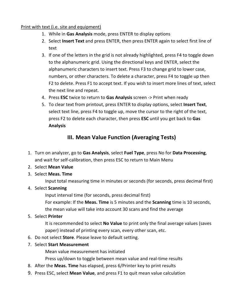
III. Mean Value Function (Averaging Tests)
1. Turn on analyzer, go to Gas Analysis, select Fuel Type, press No for Data Processing,
and wait for self-calibration, then press ESC to return to Main Menu
2. Select Mean Value
3. Select Meas. Time
Input total measuring time in minutes or seconds (for seconds, press decimal first)
4. Select Scanning
Input interval time (for seconds, press decimal first)
For example: If the Meas. Time is 5 minutes and the Scanning time is 10 seconds,
the mean value will take into account 30 scans and find the average
5. Select Printer
It is recommended to select No Value to print only the final average values (saves
paper) instead of printing every scan, every other scan, etc.
6. Do not select Store. Please leave to default setting.
7. Select Start Measurement
Mean value measurement has initiated
Press up/down to toggle between mean value and real-time results
8. After the Meas. Time has elapsed, press 6/Printer key to print results
9. Press ESC, select Mean Value, and press F1 to quit mean value calculation