operating instructions proline fieldcheck - axon...
TRANSCRIPT

BA067D/06/en/04.04
50100085
Valid as of software version
V 1.02.XX
Operating Instructions
Proline FieldcheckFlow simulator
E+
-

Proline Fieldcheck Table of contents
Endress+Hauser 3
Table of contents
1 Safety instructions . . . . . . . . . . . . . . . . 4
1.1 Designated use . . . . . . . . . . . . . . . . . . . . . . . . . . . . 4
1.2 Operational safety . . . . . . . . . . . . . . . . . . . . . . . . . . 4
1.3 Notes on operating Fieldcheck in an environment with
strong electromagnetic interference . . . . . . . . . . . . . 4
1.3.1 Radiated RF noise (EN 61326-1) . . . . . . . . . 4
1.4 Notes on safety conventions and icons . . . . . . . . . . . 5
2 Identification . . . . . . . . . . . . . . . . . . . . 6
2.1 Device designation . . . . . . . . . . . . . . . . . . . . . . . . . 6
2.1.1 Fieldcheck nameplate . . . . . . . . . . . . . . . . . 6
2.1.2 Simubox nameplate . . . . . . . . . . . . . . . . . . . 6
2.2 Scope of delivery . . . . . . . . . . . . . . . . . . . . . . . . . . . 7
2.3 CE mark, Declaration of conformity . . . . . . . . . . . . . 7
2.4 Registered trademarks . . . . . . . . . . . . . . . . . . . . . . . 7
3 Wiring . . . . . . . . . . . . . . . . . . . . . . . . . 8
3.1 Overview . . . . . . . . . . . . . . . . . . . . . . . . . . . . . . . . 8
3.2 Connecting to Promag 10 . . . . . . . . . . . . . . . . . . . . 9
3.3 Connecting to Promag 50/53 compact version . . . 10
3.4 Connecting to Promag 50/53 remote version . . . . 11
3.5 Connecting to Promass 40/80/83 compact version 12
3.6 Connecting to Promass 80/83 remote version . . . . 13
3.7 Connecting to Prowirl 72 . . . . . . . . . . . . . . . . . . . 14
3.7.1 Prowirl 72 wiring diagram . . . . . . . . . . . . . 15
3.8 Assignment of Fieldcheck connections . . . . . . . . . . 16
3.9 Post-connection check . . . . . . . . . . . . . . . . . . . . . . 16
4 Operation . . . . . . . . . . . . . . . . . . . . . . 17
4.1 Display and operating elements . . . . . . . . . . . . . . . 17
4.1.1 Display . . . . . . . . . . . . . . . . . . . . . . . . . . . 18
4.1.2 Display icons . . . . . . . . . . . . . . . . . . . . . . . 19
4.2 Brief operating instructions on the function matrix . 20
4.2.1 General notes . . . . . . . . . . . . . . . . . . . . . . 20
4.3 Communication . . . . . . . . . . . . . . . . . . . . . . . . . . 21
4.3.1 FieldTool™ operating program . . . . . . . . . 21
5 Commissioning. . . . . . . . . . . . . . . . . . 22
5.1 Function check . . . . . . . . . . . . . . . . . . . . . . . . . . . 22
5.2 Commissioning . . . . . . . . . . . . . . . . . . . . . . . . . . . 22
5.2.1 Charging the battery . . . . . . . . . . . . . . . . . 22
6 Maintenance. . . . . . . . . . . . . . . . . . . . 23
7 Accessories. . . . . . . . . . . . . . . . . . . . . 24
7.1 Software history . . . . . . . . . . . . . . . . . . . . . . . . . . 24
8 Technical data . . . . . . . . . . . . . . . . . . 25
8.1 Technical data at a glance . . . . . . . . . . . . . . . . . . . 25
8.1.1 Input . . . . . . . . . . . . . . . . . . . . . . . . . . . . . 25
8.1.2 Output . . . . . . . . . . . . . . . . . . . . . . . . . . . 25
8.1.3 Power supply . . . . . . . . . . . . . . . . . . . . . . . 25
8.1.4 Performance characteristics . . . . . . . . . . . . 25
8.1.5 Operating conditions (Environment) . . . . . . 25
8.1.6 Mechanical construction . . . . . . . . . . . . . . 26
8.1.7 Display and user interface . . . . . . . . . . . . . 26
8.1.9 Accessories . . . . . . . . . . . . . . . . . . . . . . . . 26
8.1.10 Documentation . . . . . . . . . . . . . . . . . . . . . 26
9 Description of device functions -
General section . . . . . . . . . . . . . . . . . . 27
9.1 Notes on the description of device functions . . . . . . 27
9.1.1 Using the table of contents to locate a function
description . . . . . . . . . . . . . . . . . . . . . . . . . 27
9.1.2 Using the graphic of the function matrix to
locate a function description . . . . . . . . . . . 27
9.2 Function matrix . . . . . . . . . . . . . . . . . . . . . . . . . . . 28
9.3 Block USER INTERFACE . . . . . . . . . . . . . . . . . . . . 29
9.3.1 Group CONTROL . . . . . . . . . . . . . . . . . . . 29
9.4 Block BASIC FUNCTIONS . . . . . . . . . . . . . . . . . . . 31
9.4.1 Group SENSOR PARAMETER . . . . . . . . . . 32
9.4.2 Group OUTPUTS . . . . . . . . . . . . . . . . . . . . 33
9.4.3 Group PROCESS PARAMETER . . . . . . . . . 34
9.4.4 Group READ IN PARAMETERS . . . . . . . . . 35
9.5 Block SUPERVISION . . . . . . . . . . . . . . . . . . . . . . . 36
9.5.1 Group RESULTS . . . . . . . . . . . . . . . . . . . . 36
9.5.2 Group VERSION INFO . . . . . . . . . . . . . . . 38
10 Description of device functions -
Fieldcheck and electromagnetic
measuring devices . . . . . . . . . . . . . . . . 39
10.1 Block FUNCTION . . . . . . . . . . . . . . . . . . . . . . . . . 39
10.1.1 Group SIMULATION . . . . . . . . . . . . . . . . . 40
10.1.2 Group VERIFICATION . . . . . . . . . . . . . . . 44
11 Description of device functions -
Fieldcheck and Coriolis measuring
systems . . . . . . . . . . . . . . . . . . . . . . . . 49
11.1 Block FUNCTION . . . . . . . . . . . . . . . . . . . . . . . . . 49
11.1.1 Group SIMULATION . . . . . . . . . . . . . . . . . 50
11.1.2 Group VERIFICATION . . . . . . . . . . . . . . . 53
12 Description of device functions -
Fieldcheck and vortex measuring
systems . . . . . . . . . . . . . . . . . . . . . . . . 59
12.1 Block FUNCTION . . . . . . . . . . . . . . . . . . . . . . . . . 59
12.1.1 Group SIMULATION . . . . . . . . . . . . . . . . . 60
12.1.2 Group VERIFICATION . . . . . . . . . . . . . . . 63
Index . . . . . . . . . . . . . . . . . . . . . . . . . . . . . . 68
Safety instructions Proline Fieldcheck
4 Endress+Hauser
1 Safety instructions
1.1 Designated use
The Fieldcheck flow simulation system may only be used for the simulation of sensor signals with a
flowmeter of the Proline equipment generation from Endress+Hauser. The device is normally
installed by service technicians who are familiar with the function and operating method of the
equipment. The manufacturer accepts no liability for damages resulting from incorrect use.
# Warning!
Fieldcheck may not be used in hazardous areas without corresponding safety measures.
1.2 Operational safety
• The manufacturer reserves the right to modify technical data without prior notice. Please contact
your E+H distributor for information on modifications or updates of these Operating Instructions.
• The measuring system complies with the general safety requirements in accordance with EN
61010, the EMC requirements of EN 61326/A1 and NAMUR Recommendation NE 21.
1.3 Notes on operating Fieldcheck in an environment with
strong electromagnetic interference
1.3.1 Radiated RF noise (EN 61326-1)
To operate Fieldcheck with a Proline flowmeter in the simulation and verification mode, the
electronics and connection compartments must first be opened. In this mode, the radiated RF noise
will not exceed the industrial limits (EN 61326-1).
In a heavily disturbed (EMC) environment, you must expect that the operation of both Fieldcheck
and the flowmeter may be temporarily affected. We recommend that - when using Fieldcheck - you
take care to ensure effective ESD protection for the affected measuring point and the operator.
If necessary, the measuring equipment can be reset:
• Via the local controls
• By interrupting the voltage supply
• By restarting Fieldcheck.

Proline Fieldcheck Safety instructions
Endress+Hauser 5
1.4 Notes on safety conventions and icons
The devices are designed to meet state-of-the-art safety requirements, have been tested, and left the
factory in a condition in which they are safe to operate. The devices comply with the applicable
standards and regulations in accordance with EN 61010 “Protection Measures for Electrical
Equipment for Measurement, Control, Regulation and Laboratory Procedures”. They can, however,
be a source of danger if used incorrectly or for other than the designated use.
Consequently, always pay particular attention to the safety instructions indicated in these Operating
Instructions by the following icons:
# Warning!
“Warning” indicates an action or procedure which, if not performed correctly, can result in injury
or a safety hazard. Comply strictly with the instructions and proceed with care.
" Caution!
“Caution” indicates an action or procedure which, if not performed correctly, can result in incorrect
operation or destruction of the device. Comply strictly with the instructions.
! Note!
“Note” indicates an action or procedure which, if not performed correctly, can have an indirect
effect on operation or trigger an unexpected response on the part of the device.
Identification Proline Fieldcheck
6 Endress+Hauser
2 Identification
2.1 Device designation
The Fieldcheck flow simulation system consists of the following components:
• The Fieldcheck flow simulator itself
• The Simubox for correct connection to the respective measuring device
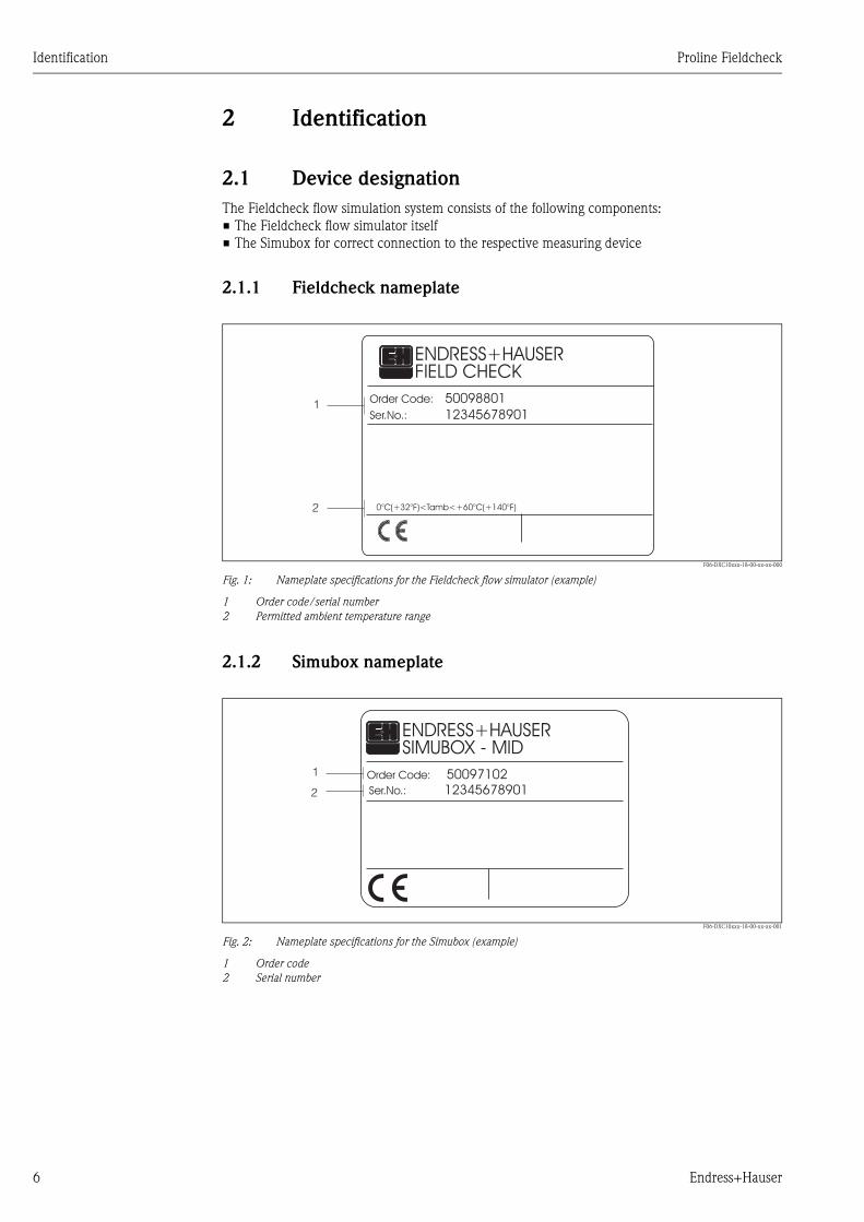
2.1.1 Fieldcheck nameplate
F06-DXC10xxx-18-00-xx-xx-000
Fig. 1: Nameplate specifications for the Fieldcheck flow simulator (example)
1 Order code/serial number
2 Permitted ambient temperature range
2.1.2 Simubox nameplate
F06-DXC10xxx-18-00-xx-xx-001
Fig. 2: Nameplate specifications for the Simubox (example)
1 Order code
2 Serial number
FIELD CHECKENDRESS+HAUSER
Order Code:
Ser.No.:
50098801
12345678901
0°C(+32°F)<Tamb<+60°C(+140°F)
1
2
4
SIMUBOX - MIDENDRESS+HAUSER
Order Code: 500971021
2 Ser.No.: 12345678901

Proline Fieldcheck Identification
Endress+Hauser 7
2.2 Scope of delivery
The equipment supplied with Fieldcheck comprises the following components:
• The Fieldcheck flow simulator with battery pack
• A connecting cable for the service interface
• A connecting cable for the Simubox
• Two connecting cables for current and frequency output
• An "RS 232" connecting cable for connecting the Fieldcheck to a computer (9-pin COM interface)
• A line adapter
• A softcase
• Operating Instructions
The Simuboxes for the respective flow measuring systems are available via separate order numbers.
2.3 CE mark, Declaration of conformity
The devices are designed to meet state-of-the-art safety requirements, have been tested, and left the
factory in a condition in which they are safe to operate. The devices comply with the applicable
standards and regulations in accordance with EN 61010 “Protection Measures for Electrical
Equipment for Measurement, Control, Regulation and Laboratory Procedures”.
The measuring system described in these Operating Instructions thus complies with the statutory
requirements of the EC Directives. Endress+Hauser confirms successful testing of the device by
affixing the CE mark.
2.4 Registered trademarks
FieldTool™, Fieldcheck™
Registration-pending or registered trademarks of Endress+Hauser Flowtec AG, Reinach,
Switzerland

Wiring Proline Fieldcheck
8 Endress+Hauser
3 Wiring
# Warning!
When connecting Ex-certified devices, see the notes and diagrams in the Ex-specific supplement to
these Operating Instructions of the relevant measuring device. Fieldcheck may not be used in
hazardous areas. Please do not hesitate to contact your E+H representative if you have any
questions.
3.1 Overview
Fieldcheck is connected to the following transmitter connections:
• Via the Simubox to the transmitter amplifier
• To the transmitter service plug
• To the current or frequency output.
For correct synchronisation with the measuring device we recommend that you abide by the
following procedure.
1. Start the device to be tested.
2. First connect the cables to the flowmeter (→ Page 9 to Page 14).
3. Next, connect the cables to the front of Fieldcheck (→ Page 16).
! Note!
Fieldcheck does not need an external power supply during operation. Power is provided by internal
storage batteries. Make sure that the storage batteries are fully charged before beginning a
simulation.

Proline Fieldcheck Wiring
Endress+Hauser 9
3.2 Connecting to Promag 10
" Caution!
Connect the ground terminals on the cables to the uninsulated housing components or to the
ground terminals in the cover of the connection compartment.
1. Remove cover of the electronics compartment (c).
2. Remove the local display (d) from the connection compartment cover.
3. Press the side latches (e) and fold down the connection compartment cover.
4. Pull the sensor signal cable plug out of the amplifier socket (f).
5. Insert Simubox cable plug into the amplifier socket (f).
6. Connect Fieldcheck to current and pulse output (g) of the transmitter.
! Note!
The configuration of the outputs is dependent on the product type and the product version of
the tested transmitter. To find out which terminal pairs are assigned to the outputs, see the
“Wiring” chapter of the flowmeter Operating Instructions.
7. Connect FieldCheck to the service plug (h).
F06-DXC10xxx-04-00-xx-xx-007
Fig. 3: Connecting Fieldcheck to Promag 5X (compact version)
a Fieldcheck flow simulator
b Simubox
c Electronics compartment cover
d Local display
e Latches
f Amplifier socket
g Terminals for current/pulse output
h Service plug-in jack
12
f
h
gEsc
a
b
d
c
e

Wiring Proline Fieldcheck
10 Endress+Hauser
3.3 Connecting to Promag 50/53 compact version
" Caution!
Connect the ground terminals on the cables to the uninsulated housing components or to the
ground terminals in the cover of the connection compartment.
1. Remove cover of the electronics compartment (e).
2. Pull local display (f) down.
3. Pull the sensor signal cable plug out of the amplifier socket (g).
4. Insert Simubox cable plug into the amplifier socket (g).
5. Remove the cover of the connection compartment (h) from the transmitter housing.
6. Connect Fieldcheck to the current and frequency outputs of the transmitter (terminal pairs
22/23, 24/25 or 26/27).
! Note!
The configuration of the outputs is dependent on the product type and the product version of
the tested transmitter. To find out which terminal pairs are assigned to the outputs, see the
“Wiring” chapter of the flowmeter Operating Instructions.
7. Connect Fieldcheck to the service plug (i).
F06-DXC10xxx-04-00-xx-xx-000
Fig. 4: Connecting Fieldcheck to Promag 5X (compact version)
a Fieldcheck flow simulator
b Simubox
c Stainless steel transmitter
d Aluminium transmitter
e Electronics compartment cover
f Local display
g Amplifier socket
h Connection compartment cover
I Service plug
27
25
23
21
21
26
24
22
20
L1 (L+)N (L-)
E- +
h
c
e
d
h
e
g
f
b
a
i
Proline Fieldcheck Wiring
Endress+Hauser 11
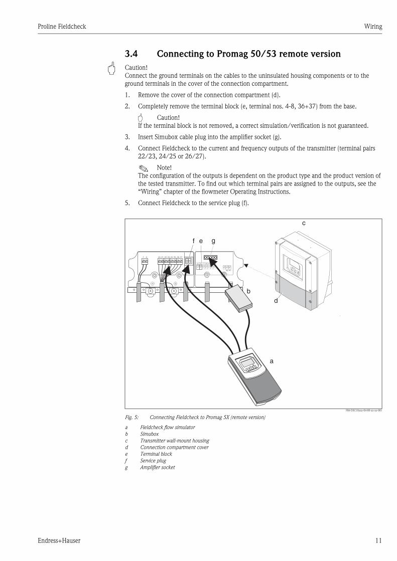
3.4 Connecting to Promag 50/53 remote version
" Caution!
Connect the ground terminals on the cables to the uninsulated housing components or to the
ground terminals in the cover of the connection compartment.
1. Remove the cover of the connection compartment (d).
2. Completely remove the terminal block (e, terminal nos. 4-8, 36+37) from the base.
" Caution!
If the terminal block is not removed, a correct simulation/verification is not guaranteed.
3. Insert Simubox cable plug into the amplifier socket (g).
4. Connect Fieldcheck to the current and frequency outputs of the transmitter (terminal pairs
22/23, 24/25 or 26/27).
! Note!
The configuration of the outputs is dependent on the product type and the product version of
the tested transmitter. To find out which terminal pairs are assigned to the outputs, see the
“Wiring” chapter of the flowmeter Operating Instructions.
5. Connect Fieldcheck to the service plug (f).
F06-DXC10xxx-04-00-xx-xx-001
Fig. 5: Connecting Fieldcheck to Promag 5X (remote version)
a Fieldcheck flow simulator
b Simubox
c Transmitter wall-mount housing
d Connection compartment cover
e Terminal block
f Service plug
g Amplifier socket
1 2 22 2320 21 24 25 26 27
4142
6 5 7 8 4 37 36
c
d
e gf
b
a
Wiring Proline Fieldcheck
12 Endress+Hauser
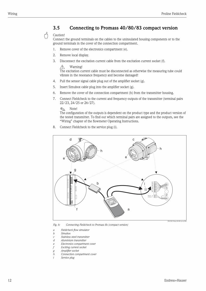
3.5 Connecting to Promass 40/80/83 compact version
" Caution!
Connect the ground terminals on the cables to the uninsulated housing components or to the
ground terminals in the cover of the connection compartment.
1. Remove cover of the electronics compartment (e).
2. Remove local display.
3. Disconnect the excitation current cable from the excitation current socket (f).
# Warning!
The excitation current cable must be disconnected as otherwise the measuring tube could
vibrate in the resonance frequency and become damaged!
4. Pull the sensor signal cable plug out of the amplifier socket (g).
5. Insert Simubox cable plug into the amplifier socket (g).
6. Remove the cover of the connection compartment (h) from the transmitter housing.
7. Connect Fieldcheck to the current and frequency outputs of the transmitter (terminal pairs
22/23, 24/25 or 26/27).
! Note!
The configuration of the outputs is dependent on the product type and the product version of
the tested transmitter. To find out which terminal pairs are assigned to the outputs, see the
“Wiring” chapter of the flowmeter Operating Instructions.
8. Connect Fieldcheck to the service plug (i).
F06-DXC10xxx-04-00-xx-xx-004
Fig. 6: Connecting Fieldcheck to Promass 8x (compact version)
a Fieldcheck flow simulator
b Simubox
c Stainless steel transmitter
d Aluminium transmitter
e Electronics compartment cover
f Exciting current socket
g Amplifier socket
h Connection compartment cover
i Service plug
27
25
23
21
21
26
24
22
20
L1 (L+)N (L-)
h
c
e
d
h
e
g
f
b
a
i

Proline Fieldcheck Wiring
Endress+Hauser 13
3.6 Connecting to Promass 80/83 remote version
" Caution!
Connect the ground terminals on the cables to the uninsulated housing components or to the
ground terminals in the cover of the connection compartment.
1. Remove the cover of the connection compartment (d).
2. Remove excitation current cable (h, terminal pair 41/42).
# Warning!
The excitation current cable must be removed as otherwise the measuring tube could vibrate
in the resonance frequency and become damaged!
3. Completely remove the terminal block (e, terminals 4-12) from the base.
" Caution!
If the terminal block is not removed, a correct simulation/verification is not guaranteed.
4. Insert Simubox cable plug into the amplifier socket (g).
5. Connect Fieldcheck to the current and frequency outputs of the transmitter (terminal pairs
22/23, 24/25 or 26/27).
! Note!
The configuration of the outputs is dependent on the product type and the product version of
the tested transmitter. To find out which terminal pairs are assigned to the outputs, see the
“Wiring” chapter of the flowmeter Operating Instructions.
6. Connect Fieldcheck to the service plug (f).
F06-DXC10xxx-04-00-xx-xx-005
Fig. 7: Connecting Fieldcheck to Promass 8X (remote version)
a Fieldcheck flow simulator
b Simubox
c Transmitter wall-mount housing
d Connection compartment cover
e Terminals for sensor signal cable
f Service plug
g Amplifier socket
h Terminals for excitation current cable
1 2 22 2320 21 24 25 26 27
41 42
65 7 84 9 10 11 12
c
d
egf
b
a
h

Wiring Proline Fieldcheck
14 Endress+Hauser
3.7 Connecting to Prowirl 72
" Caution!
Connect the ground terminals on the cables to the uninsulated housing components or to the
ground terminals in the cover of the connection compartment.
1. Remove cover of the electronics compartment (c).
2. Remove the local display module (d) from the retainer rails (e).
3. Fit the local display module (d) with its left side onto the right retainer rail (e) (this secures the
local display module).
(Continued on next page)
F06-DXC10xxx-04-00-xx-xx-006
Fig. 8: Connecting Fieldcheck to Prowirl 72
a Fieldcheck
b Simubox
c Electronics compartment cover
d Local display module
e Local display module retainer rails
f Fixing screw for cover of connection compartment
g Connection compartment cover
h Terminals for current output/power supply and pulse output (optional)
i Plastic cover
j Amplifier socket
k Service plug
b
a
e
gf
d
c
g
i
i
j
k
h
Proline Fieldcheck Wiring
Endress+Hauser 15
4. Loosen the fixing screw (f) of the cover of the connection compartment (g) and fold down the
cover.
5. Connect Fieldcheck to the current output/power supply and to the pulse output if available.
The terminals can be disconnected for this.
" Caution!
– The current output can only be tested for accuracy during the verification if it is connected
to the current input of Fieldcheck.
– The pulse output is connected to the frequency input of Fieldcheck.
6. Fold up the plastic cover (i).
7. Disconnect the signal cable plug from the amplifier socket (j).
8. Insert Simubox cable plug into the amplifier socket (j).
9. Connect Fieldcheck to the service plug (k).
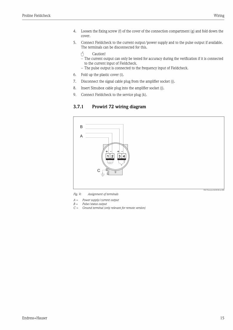
3.7.1 Prowirl 72 wiring diagram
F06-72xxxxxx-04-00-00-xx-000
Fig. 9: Assignment of terminals
A = Power supply/current output
B = Pulse/status output
C = Ground terminal (only relevant for remote version)
1 2 3 4
A
C
+ +- -
B

Wiring Proline Fieldcheck
16 Endress+Hauser
3.8 Assignment of Fieldcheck connections
F06-DXC10xxx-04-00-xx-xx-003
Fig. 10: Fieldcheck connection diagram on the front panel
1 Connection to the frequency output of the device
2 Connection to the current output of the device
3 Connection to the internal service interface of the device
4 Connection to the Simubox
5 Connection to the plug power unit
3.9 Post-connection check
• Fieldcheck can only complete the start-up procedure correctly if the simulation box and the
service cable are correctly connected.
• Current and frequency outputs which are incorrectly connected or mixed up result in an incorrect
verification result.
1 2 3 4 5
DCSIMSRVIF

Proline Fieldcheck Operation
Endress+Hauser 17
4 Operation
4.1 Display and operating elements
The local display enables you to read all important variables of the simulation and configure the
device using the function matrix.
F06-DXC10xxx-07-xx-xx-xx-000
Fig. 11: Display and operating elements
1 Liquid crystal display
The backlit, liquid crystal display shows measured values, dialog texts, fault messages and information messages.
The HOME position (operating mode) is the name given to the display during normal measuring operation.
2 Optical operating elements for "Touch Control"
3 Plus/minus keys
– Enter numerical values, select parameters
– Select different blocks, groups and function groups within the function matrix
The following functions are activated by pressing the +/- keys (X) simultaneously:
– Exit the function matrix step by step → HOME position
– Press the +/- keys longer than 3 seconds → Direct return to the HOME position
– Cancel data entry
4 Enter key
– HOME position → Enter the function matrix
– Save numerical values entered or altered settings
Esc
E+-
1
2
3 4
+7.000+7.012
dm3/mdm3/m
MP1 5 %
V
+7.000+7.012
dm3/mdm3/m
MP1 5 %
V

Operation Proline Fieldcheck
18 Endress+Hauser
4.1.1 Display
The display area consists of three to four lines; this is where measured values are displayed, and/or
status variables (sequence information of a verification.
F06-DXC10xxx-07-xx-xx-xx-001
Fig. 12: Typical display for normal operating mode (HOME position)
1 Main line: shows simulation values, e.g. volume flow in [dm3/s]
2 Additional line: shows up-to-date measured values of the tested measuring device]
3 Information line: shows the current variables for current and frequency if the corresponding outputs of the device
are connected to Fieldcheck. This is only possible in the SIMULATION operating mode
4 “Information icons” field: icons representing additional information on the measured values are shown in this field.
See figure for a full list of the icons and their meanings.
5 “Measured values” field: the current measured values appear in this field.
6 “Unit of measurement” field: the units of measure and time defined for the flow values appear in this field.
1
4 5 6
2
3
+7.000+7.012
dm3/mdm3/m
I = 17,12 mA F = 783 Hz
V

Proline Fieldcheck Operation
Endress+Hauser 19
4.1.2 Display icons
The icons which appear in the field on the left make it easier to read and recognise error messages
locally.
F06-DXC10xxx-07-xx-xx-xx-002
Fig. 13: Fieldcheck display icons
1 DC power supply
2 Charging status: battery fully charged
3 Charging status: battery 2/3 charged
4 Charging status: battery 1/3 charged (flashing in HOME position)
5 Simulation “continuous"
6 Simulation “step"
7 Simulation “profile"
8 Verification
9 Measured volume flow
10 Measured mass flow
1 2 3 4
5
9
6 7 8
V10
m

Operation Proline Fieldcheck
20 Endress+Hauser
4.2 Brief operating instructions on the function matrix
! Note!
• See the general notes on Page 20.
• Description of functions → Section 9 to Section 12
1. HOME position → F → Enter the function matrix
2. Select a block (e.g. USER INTERFACE)
3. Select a group (e.g. CONTROL)
4. Select a function group (e.g. BASIC CONFIGURATION)
5. Select a function (e.g. LANGUAGE)
Change parameter / enter numerical values:
P → Select or enter release code, parameters, numerical values
F → Save your entries
6. Exit the function matrix:
– Press Esc key (X) longer than 3 seconds → HOME position
– Repeatedly press Esc key (X) → Return step by step to HOME position
F06-x3xxxxxx-19-xx-xx-xx-000
Fig. 14: Selecting functions and configuring parameters (function matrix)
4.2.1 General notes
The function matrix comprises a multiplicity of functions which, for the sake of clarity, are arranged
on a number of menu levels (blocks, groups and function groups).
Proline Fieldcheck Operation
Endress+Hauser 21
Comply with the following instructions when configuring functions:
You select functions as described on Page 20.
! Note!
A detailed description of all the functions as well as a detailed overview of the function matrix are
provided in Sections 9 to 12.
4.3 Communication
Operation via a personal computer using the “FieldTool” operating software.
4.3.1 FieldTool™ operating program
FieldTool™ is a universal service and configuration software package designed for the Proline
measuring devices. The connection is made with a commercial serial cable (9-pole DSUB, 0-
Modem) to the underside of Fieldcheck.
FieldTool™ offers the user the following fields of application:
• Configuring the equipment functions.
• Archiving the verification data.
• Printout of a verification certificate with all measuring results and I/O parameters.
You can find more information on FieldTool™ in the following E+H document:
System Information: SI 031D/06/en “FieldTool™"
Commissioning Proline Fieldcheck
22 Endress+Hauser
5 Commissioning
5.1 Function check
Make sure that Fieldcheck is correctly connected to the measuring device that is to be simulated
(→ Page 8 ff.). The measuring device must be working free of errors in order for a simulation or
verification to be started.
5.2 Commissioning
Fieldcheck is powered via an adapter or via the storage battery included in the delivery. Before the
simulation, make sure that the storage batteries are fully charged. To ensure correct commissioning
you are advised to abide by the processes as they are described on Page 8 ff.
Fieldcheck switches itself on automatically as soon as one of the connecting cables is inserted.
Fieldcheck performs a number of self-tests after power-on. As this procedure progresses, diverse
messages which have to be acknowledged appear on the local display.
You know that Fieldcheck is ready for operation when the HOME position appears on the display.
If batteries are being used, the charge status of the battery pack also appears (Page 19 ff.).
5.2.1 Charging the battery
The battery is charged automatically as soon as the power unit or the car-adapter cable is connected
to Fieldcheck. The charging time is less than 3 hours if there is no simulation in progress. When the
battery is fully charged it is switched to conservation charging. The charging time is considerably
longer during a simulation.
The charge status is displayed in the HOME position via the charge status icon (Page 19 ff.).

Proline Fieldcheck Maintenance
Endress+Hauser 23
6 Maintenance
Fieldcheck requires no special maintenance.
" Caution!
To prevent a low discharge of the battery in case of not using Fieldcheck for a longer period it is
recommended to charge the device every quarter of a year.
Exterior cleaning
When cleaning the exterior of measuring devices, always use cleaning agents that do not attack the
surface of the housing.

Accessories Proline Fieldcheck
24 Endress+Hauser
7 Accessories
Various accessories can be supplied for Fieldcheck and they can be ordered separately from
Endress+Hauser. The E+H service organisation can provide detailed information on the order code
of your choice.
7.1 Software history
Accessory Description Order code
FieldTool™ Configuration and service software for flowmeters in the
field:
– Commissioning, maintenance analysis
– Configuring flowmeters
– Service functions
– Visualisation of process data
– Troubleshooting
– Controlling the “Fieldcheck™” tester/simulator
Contact your E+H representative for more information.
DXS10 - * * * * *
Simubox MID for FieldCheck Serves communication between FieldCheck and
electromagnetic flowmeters.
50097102
Simubox Coriolis for FieldCheck Serves communication between FieldCheck and Coriolis
mass flowmeters.
50097101
Plug-in power unit 85260 VAC Power unit for charging the battery and the operation of
FieldCheck at the mains
50095659
Car adapter 12 VDC Adapter for connecting to the car battery. 50095660
NiMH AccuPack Additional battery 50095661
Softcase Practical storage bag 50095662
Simubox/FieldCheck connecting cable For connecting the Simubox to FieldCheck 50095663
Proline measuring device/FieldCheck
interface cable
For connecting FieldCheck to the internal service
interface of the flowmeter
50097100
FieldCheckcurrent or frequency
output measuring cable
For connecting FieldCheck to the current or frequency
output of the flowmeter
50095664
FC/Tooling interface cable For connecting FieldCheck to the Tooling computer 50098800
Software version / date Changes to software Changes to documentation
V 1.00.00 - -
V 1.00.01/11.2001 Device release -
V 1.00.02/08.2002 Software adaptation -
V 1.01.00/07.2003 Software extension for Coriolis flow
measuring systems
Operating Instructions
V 1.02.00/04.2004 Software extension for Prowirl 72 Operating Instructions

Proline Fieldcheck Technical data
Endress+Hauser 25
8 Technical data
8.1 Technical data at a glance
8.1.1 Input
Measured variable Current input, frequency input
Measuring range 0...25 mA, 0...15000 Hz
8.1.2 Output
Output signal Electromagnetic: simulation voltage
Coriolis: 2 phase-shifted sinusoidal signals
Galvanic isolation Yes
8.1.3 Power supply
Electrical connections Input for power unit: 100-240 V AC (47-63 Hz) Prim., 12 V DC (2.5 A) Sec.
Supply voltage 12 V DC, internal battery 7.2 V, 3800 mAh
Power consumption 140 mA
Charging current: max. 2A (max. 350 mA for simultaneous operation)
8.1.4 Performance characteristics
Reference operating
conditions
+22 °C ± 2K
Max. measured error for
outputs
Electromagnetic measuring device
Voltage ±0.2 % of full scale (0.150 ... 20 mV)
Coriolis measuring device:
Phase difference ±0.2 % of full scale
Max. measured error for
inputs
Current
± 5 µA (0 ... 25 mA)
Frequency
< 0.5 Hz (0 ...15 kHz)
8.1.5 Operating conditions (Environment)
Ambient temperature range 0 ... 60°C
Electromagnetic compatibility
(EMC)
In accordance with EN 61326/A1 and NAMUR Recommendation NE 21
Technical data Proline Fieldcheck
26 Endress+Hauser
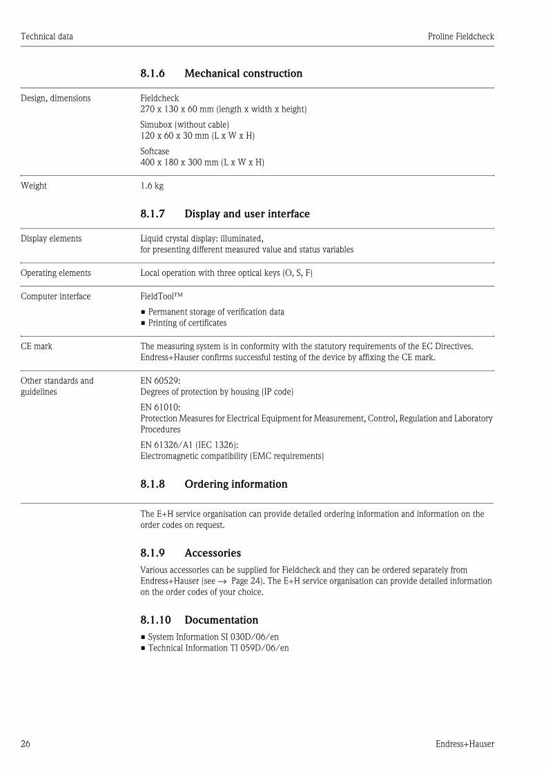
8.1.6 Mechanical construction
Design, dimensions Fieldcheck
270 x 130 x 60 mm (length x width x height)
Simubox (without cable)
120 x 60 x 30 mm (L x W x H)
Softcase
400 x 180 x 300 mm (L x W x H)
Weight 1.6 kg
8.1.7 Display and user interface
Display elements Liquid crystal display: illuminated,
for presenting different measured value and status variables
Operating elements Local operation with three optical keys (O, S, F)
Computer interface FieldTool™
• Permanent storage of verification data
• Printing of certificates
CE mark The measuring system is in conformity with the statutory requirements of the EC Directives.
Endress+Hauser confirms successful testing of the device by affixing the CE mark.
Other standards and
guidelines
EN 60529:
Degrees of protection by housing (IP code)
EN 61010:
Protection Measures for Electrical Equipment for Measurement, Control, Regulation and Laboratory
Procedures
EN 61326/A1 (IEC 1326):
Electromagnetic compatibility (EMC requirements)
8.1.8 Ordering information
The E+H service organisation can provide detailed ordering information and information on the
order codes on request.
8.1.9 Accessories
Various accessories can be supplied for Fieldcheck and they can be ordered separately from
Endress+Hauser (see → Page 24). The E+H service organisation can provide detailed information
on the order codes of your choice.
8.1.10 Documentation
• System Information SI 030D/06/en
• Technical Information TI 059D/06/en
Proline Fieldcheck Description of device functions - General section
Endress+Hauser 27
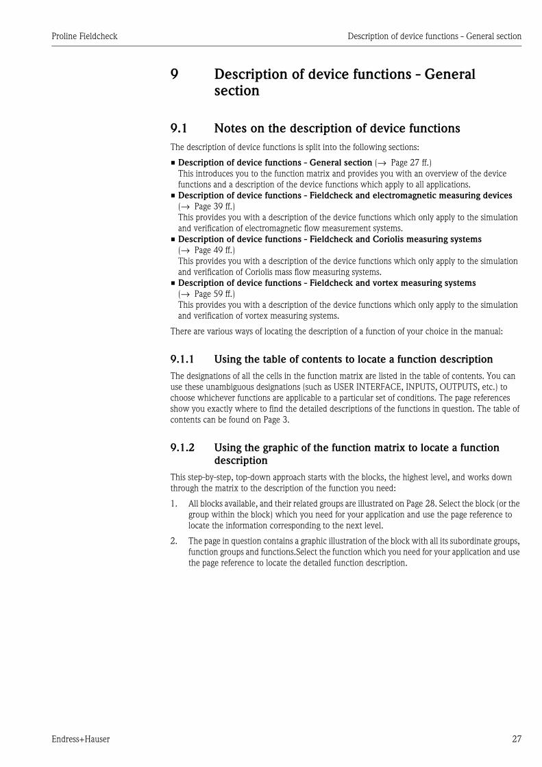
9 Description of device functions - General section
9.1 Notes on the description of device functions
The description of device functions is split into the following sections:
• Description of device functions - General section (→ Page 27 ff.)
This introduces you to the function matrix and provides you with an overview of the device
functions and a description of the device functions which apply to all applications.
• Description of device functions - Fieldcheck and electromagnetic measuring devices
(→ Page 39 ff.)
This provides you with a description of the device functions which only apply to the simulation
and verification of electromagnetic flow measurement systems.
• Description of device functions - Fieldcheck and Coriolis measuring systems
(→ Page 49 ff.)
This provides you with a description of the device functions which only apply to the simulation
and verification of Coriolis mass flow measuring systems.
• Description of device functions - Fieldcheck and vortex measuring systems
(→ Page 59 ff.)
This provides you with a description of the device functions which only apply to the simulation
and verification of vortex measuring systems.
There are various ways of locating the description of a function of your choice in the manual:
9.1.1 Using the table of contents to locate a function description
The designations of all the cells in the function matrix are listed in the table of contents. You can
use these unambiguous designations (such as USER INTERFACE, INPUTS, OUTPUTS, etc.) to
choose whichever functions are applicable to a particular set of conditions. The page references
show you exactly where to find the detailed descriptions of the functions in question. The table of
contents can be found on Page 3.
9.1.2 Using the graphic of the function matrix to locate a function
description
This step-by-step, top-down approach starts with the blocks, the highest level, and works down
through the matrix to the description of the function you need:
1. All blocks available, and their related groups are illustrated on Page 28. Select the block (or the
group within the block) which you need for your application and use the page reference to
locate the information corresponding to the next level.
2. The page in question contains a graphic illustration of the block with all its subordinate groups,
function groups and functions.Select the function which you need for your application and use
the page reference to locate the detailed function description.

Description of device functions - General section Proline Fieldcheck
28 Endress+Hauser
9.2 Function matrix
BLOCKS GROUPS FUNCTIONS
FUNCTION
Proline Promag: Page 39 ff.
Proline Promass: Page 49 ff.
Proline Vortex: Page 59 ff.
→ SIMULATION
Electromagnetic measuring devices (Proline
Promag)
→ Page 40 ff.
Coriolis measuring devices (Proline Promass) → Page 50 ff.
Vortex measuring devices (Proline Prowirl) → Page 60 ff.
↓ VERIFICATION
Electromagnetic measuring devices (Proline
Promag)
→ Page 44 ff.
Coriolis measuring devices (Proline Promass) → Page 53 ff.
Vortex measuring devices (Proline Prowirl) → Page 63 ff.
USER INTERFACE → CONTROL → Page 29 ff.
↓
BASIC FUNCTIONS → Sensor data → Page 32 ff.
OUTPUTS → Page 33 ff.
↓ PROCESS PARAMETER → Page 34
READ IN PARAMETERS → Page 35
SUPERVISION → RESULTS → Page 36 ff.
VERSION INFO → Page 38 ff.
Proline Fieldcheck Description of device functions - General section
Endress+Hauser 29
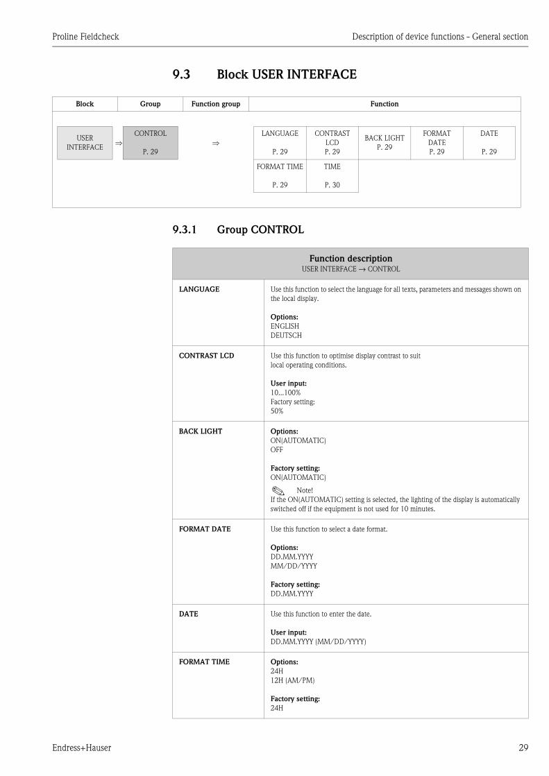
9.3 Block USER INTERFACE
9.3.1 Group CONTROL
Block Group Function group Function
USER
INTERFACE⇒
CONTROL
P. 29
⇒LANGUAGE
P. 29
CONTRAST
LCD
P. 29
BACK LIGHT
P. 29
FORMAT
DATE
P. 29
DATE
P. 29
FORMAT TIME
P. 29
TIME
P. 30
Function descriptionUSER INTERFACE → CONTROL
LANGUAGE Use this function to select the language for all texts, parameters and messages shown on
the local display.
Options:
ENGLISH
DEUTSCH
CONTRAST LCD Use this function to optimise display contrast to suit
local operating conditions.
User input:
10...100%
Factory setting:
50%
BACK LIGHT Options:
ON(AUTOMATIC)
OFF
Factory setting:
ON(AUTOMATIC)
! Note!
If the ON(AUTOMATIC) setting is selected, the lighting of the display is automatically
switched off if the equipment is not used for 10 minutes.
FORMAT DATE Use this function to select a date format.
Options:
DD.MM.YYYY
MM/DD/YYYY
Factory setting:
DD.MM.YYYY
DATE Use this function to enter the date.
User input:
DD.MM.YYYY (MM/DD/YYYY)
FORMAT TIME Options:
24H
12H (AM/PM)
Factory setting:
24H

Description of device functions - General section Proline Fieldcheck
30 Endress+Hauser
TIME Use this function to enter the time.
User input:
HH:MM
Function descriptionUSER INTERFACE → CONTROL

Proline Fieldcheck Description of device functions - General section
Endress+Hauser 31
9.4 Block BASIC FUNCTIONS
Block Group Function group Function
BASIC
FUNCTIONS⇒
SENSOR
PARAMETER
P. 32
⇒K-FACTOR
POS/NEG
P. 32
ZERO POINT
P. 32
NOMINAL
DIAMETER
P. 32
FLOW
DIRECTION
P. 32
SERIAL
NUMBER
P. 32
⇓⇑
TAG NAME.
P. 32
OUTPUTS
P. 33
⇒OUTPUT
P. 33
ASSIGN
P. 33
CURRENT
RANGE
P. 33
VALUE 0_4 mA
P. 33
VALUE 20 mA
P. 33
⇓⇑
OPERATION
MODE
P. 33
ASSIGN
P. 33
START VALUE
FREQUENCY
P. 33
END
FREQUENCY
P. 33
VALUE FLOW
P. 33
VALUE FHIGH
P. 34
PULSE VALUE
P. 34
OUTPUT
SIGNAL
P. 34
PROCESS
PARAMETER
P. 34
⇒
DENSITY
VALUE
P. 34
STANDARD
DENSITY
P. 34
OPERATING
DENSITY
P. 34
REFERENCE
DENSITY
P. 34
APPLICATION
P. 34
⇓⇑
TYPE UNIT
MEAS.
P. 34
READ IN
PARAMETERS
P. 35
⇒READ IN
PARAMETERS
P. 35
Description of device functions - General section Proline Fieldcheck
32 Endress+Hauser
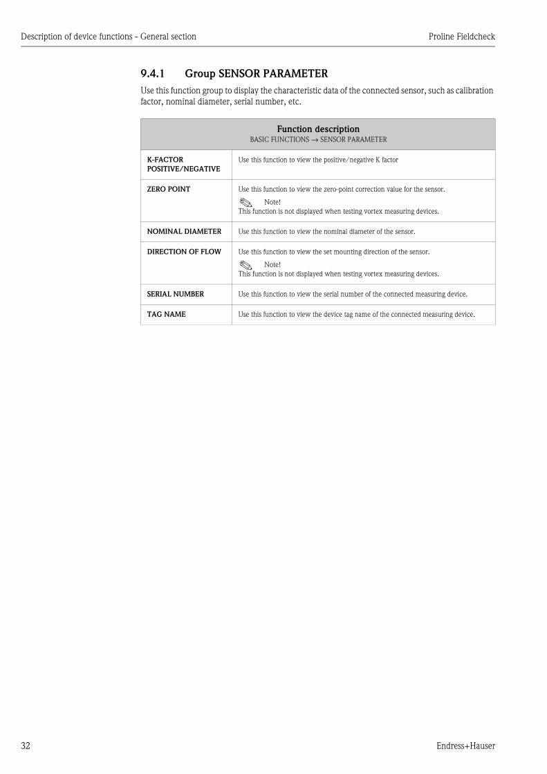
9.4.1 Group SENSOR PARAMETER
Use this function group to display the characteristic data of the connected sensor, such as calibration
factor, nominal diameter, serial number, etc.
Function descriptionBASIC FUNCTIONS → SENSOR PARAMETER
K-FACTOR
POSITIVE/NEGATIVE
Use this function to view the positive/negative K factor
ZERO POINT Use this function to view the zero-point correction value for the sensor.
! Note!
This function is not displayed when testing vortex measuring devices.
NOMINAL DIAMETER Use this function to view the nominal diameter of the sensor.
DIRECTION OF FLOW Use this function to view the set mounting direction of the sensor.
! Note!
This function is not displayed when testing vortex measuring devices.
SERIAL NUMBER Use this function to view the serial number of the connected measuring device.
TAG NAME Use this function to view the device tag name of the connected measuring device.
Proline Fieldcheck Description of device functions - General section
Endress+Hauser 33
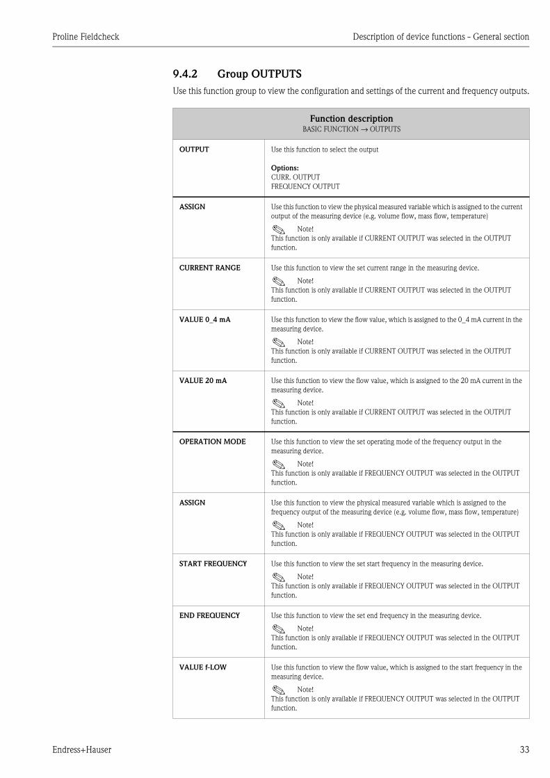
9.4.2 Group OUTPUTS
Use this function group to view the configuration and settings of the current and frequency outputs.
Function descriptionBASIC FUNCTION → OUTPUTS
OUTPUT Use this function to select the output
Options:
CURR. OUTPUT
FREQUENCY OUTPUT
ASSIGN Use this function to view the physical measured variable which is assigned to the current
output of the measuring device (e.g. volume flow, mass flow, temperature)
! Note!
This function is only available if CURRENT OUTPUT was selected in the OUTPUT
function.
CURRENT RANGE Use this function to view the set current range in the measuring device.
! Note!
This function is only available if CURRENT OUTPUT was selected in the OUTPUT
function.
VALUE 0_4 mA Use this function to view the flow value, which is assigned to the 0_4 mA current in the
measuring device.
! Note!
This function is only available if CURRENT OUTPUT was selected in the OUTPUT
function.
VALUE 20 mA Use this function to view the flow value, which is assigned to the 20 mA current in the
measuring device.
! Note!
This function is only available if CURRENT OUTPUT was selected in the OUTPUT
function.
OPERATION MODE Use this function to view the set operating mode of the frequency output in the
measuring device.
! Note!
This function is only available if FREQUENCY OUTPUT was selected in the OUTPUT
function.
ASSIGN Use this function to view the physical measured variable which is assigned to the
frequency output of the measuring device (e.g. volume flow, mass flow, temperature)
! Note!
This function is only available if FREQUENCY OUTPUT was selected in the OUTPUT
function.
START FREQUENCY Use this function to view the set start frequency in the measuring device.
! Note!
This function is only available if FREQUENCY OUTPUT was selected in the OUTPUT
function.
END FREQUENCY Use this function to view the set end frequency in the measuring device.
! Note!
This function is only available if FREQUENCY OUTPUT was selected in the OUTPUT
function.
VALUE f-LOW Use this function to view the flow value, which is assigned to the start frequency in the
measuring device.
! Note!
This function is only available if FREQUENCY OUTPUT was selected in the OUTPUT
function.

Description of device functions - General section Proline Fieldcheck
34 Endress+Hauser
9.4.3 Group PROCESS PARAMETER
VALUE f-HIGH Use this function to view the flow value, which is assigned to the end frequency in the
measuring device.
! Note!
This function is only available if FREQUENCY OUTPUT was selected in the OUTPUT
(6900) function.
PULSE VALUE Use this function to view the set pulse value in the measuring device.
! Note!
This function is only available if FREQUENCY OUTPUT was selected in the OUTPUT
(6900) function and the operating mode in the measuring device is set to PULSE.
OUTPUT SIGNAL Use this function to view the output signal settings (ACTIVE/PASSIVE,
POSITIVE/NEGATIVE).
Function descriptionBASIC FUNCTION → PROCESS PARAMETER
DENSITY VALUE ! Note!
This function only appears if a Promag 53-type electromagnetic flow measurement system
is being tested.
Use this function to view the density factor entered in the measuring device. With this
value, the volume flow is converted to a mass flow during simulation.
STANDARD DENSITY ! Note!
This function only appears if a Coriolis flow measurement system is tested.
Use this function to view the standard density entered in the measuring device. With this
value, the mass flow is converted to the corrected volume flow during simulation.
OPERATING DENSITY ! Note!
This function only appears if a vortex flow measurement system is tested.
Use this function to view the density at process conditions entered in the measuring
device. With this value, the volume flow is converted to a mass flow or corrected volume
flow during simulation.
REFERENCE DENSITY ! Note!
This function only appears if a vortex flow measurement system is tested.
Use this function to view the density at reference conditions entered in the measuring
device. With this value, the volume flow is converted to a mass flow or corrected volume
flow during simulation.
APPLICATION ! Note!
This function only appears if a vortex flow measurement system is tested.
Use this function to view the set application (liquid or gas/steam) in the measuring device.
TYPE UNIT
MEASURAND! Note!
This function only appears if a vortex flow measurement system is tested.
Use this function to view the set unit type (volume flow, calculated mass flow or calculated
corrected volume flow) in the measuring device.
Function descriptionBASIC FUNCTION → OUTPUTS

Proline Fieldcheck Description of device functions - General section
Endress+Hauser 35
9.4.4 Group READ IN PARAMETERS
Function descriptionBASIC FUNCTION → READ IN PARAMETERS
READ IN PARAMETERS Use this function to transfer the complete data record from the measuring device to
Fieldcheck, if, for example, you have changed parameters in the connected measuring
device,
Options:
START
CANCEL

Description of device functions - General section Proline Fieldcheck
36 Endress+Hauser
9.5 Block SUPERVISION
9.5.1 Group RESULTS
Block Group Function group Function
SUPERVISION
⇒
RESULTS
P. 36
⇒ STORAGE
LOC. VER.
P. 36
INFO
STORAGE
LOC.
P. 36
RESULTS VER.
MID
P. 36
RESULTS VER.
COR.
P. 37
RESULTS VER.
VOR.
P. 37
⇓⇑
DELETE
STORAGE
P. 37
STORAGE
LOCATION
P. 37
VERSION INFO
P. 38 ⇒FIELDCHECK
P. 38
⇒HW VERSION
P. 38
SW VERSION
P. 38
SERIAL
NUMBER
P. 38
CALIBRATION
DATE
P. 38
SIMUBOX
P. 38
⇒TYPE
P. 38
HW VERSION
P. 38
SW VERSION
P. 38
SERIAL
NUMBER
P. 38
CALIBRATION
DATE
P. 38
MANUFACT./
TEST DATE
P. 38
Function descriptionSUPERVISION → RESULTS
STORAGE LOCATION
VERIFICATION
Use this function to define the storage location of the verification to be displayed.
User input:
1...20
INFO STORAGE
LOCATION
Use this function to view information about the measuring device and the verification
saved in the storage location.
Display:
Main line: measuring device type
Additional line: serial number
Information line: date of verification
RESULTS
VERIFICATION
MAGMETER
Use this function to recall the results of the verification. The result (PASSED, FAILED) is
displayed in the information line.
If the results of a linearity check are recalled, the list of deviation values also appears when
confirming the selection.
Options:
FINAL RESULT
ZERO POINT (with list of deviation values)
AMPLIFIER (with list of deviation values)
CURRENT OUTPUT (with list of deviation values)
FREQ. OUT. (with list of deviation values)
PULSE MEASUREMENT (with list of deviation values)
SENSOR

Proline Fieldcheck Description of device functions - General section
Endress+Hauser 37
RESULTS
VERIFICATION
CORIOLIS
Use this function to recall the results of the verification. The result (PASSED, FAILED) is
displayed in the information line.
If the results of a linearity check are recalled, the list of deviation values also appears when
confirming the selection.
Options:
FINAL RESULT
ZERO POINT (with list of deviation values)
AMPLIFIER (with list of deviation values)
DENSITY (with list of deviation values)
TEMPERATURE (with list of deviation values)
CURRENT OUTPUT (with list of deviation values)
FREQUENCY OUTPUT (with list of deviation values)
PULSE MEASUREMENT (with list of deviation values)
SENSOR
RESULTSVERIFICATI
ON VORTEX
Use this function to recall the results of the verification. The result (PASSED, FAILED) is
displayed in the information line.
If the results of a linearity check are recalled, the list of deviation values also appears when
confirming the selection.
Options:
FINAL RESULT
ZERO POINT (with measured value for the current output)
AMPLIFIER (with list of deviation values)
CURRENT OUTPUT (with list of deviation values)
PULSE MEASUREMENT (with list of deviation values)
SENSOR
DELETE STORAGE Use this function to delete the content of the memory.
Options:
NO
STORAGE LOCATION
ALL
STORAGE LOCATION Use this function to specify the storage location whose contents should be deleted. User
input :1...20. This function does not appear unless the STORAGE LOCATION parameter
was selected in the DELETE STORAGE function.
Function descriptionSUPERVISION → RESULTS
Description of device functions - General section Proline Fieldcheck
38 Endress+Hauser
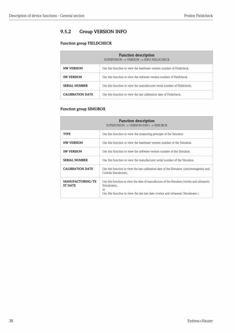
9.5.2 Group VERSION INFO
Function group FIELDCHECK
Function group SIMUBOX
Function descriptionSUPERVISION → VERSION → INFO FIELDCHECK
HW VERSION Use this function to view the hardware version number of Fieldcheck.
SW VERSION Use this function to view the software version number of Fieldcheck.
SERIAL NUMBER Use this function to view the manufacturer serial number of Fieldcheck.
CALIBRATION DATE Use this function to view the last calibration date of Fieldcheck.
Function descriptionSUPERVISION → VERSION-INFO → SIMUBOX
TYPE Use this function to view the measuring principle of the Simubox
HW VERSION Use this function to view the hardware version number of the Simubox.
SW VERSION Use this function to view the software version number of the Simubox.
SERIAL NUMBER Use this function to view the manufacturer serial number of the Simubox.
CALIBRATION DATE Use this function to view the last calibration date of the Simubox -(electromagnetic and
Coriolis Simuboxes).
MANUFACTURING/TE
ST DATE
Use this function to view the date of manufacture of the Simubox (vortex and ultrasonic
Simuboxes).
or
Use this function to view the last test date (vortex and ultrasonic Simuboxes ).
Proline Fieldcheck Description of device functions - Fieldcheck and electromagnetic measuring devices
Endress+Hauser 39
10 Description of device functions - Fieldcheck and electromagnetic measuring devices
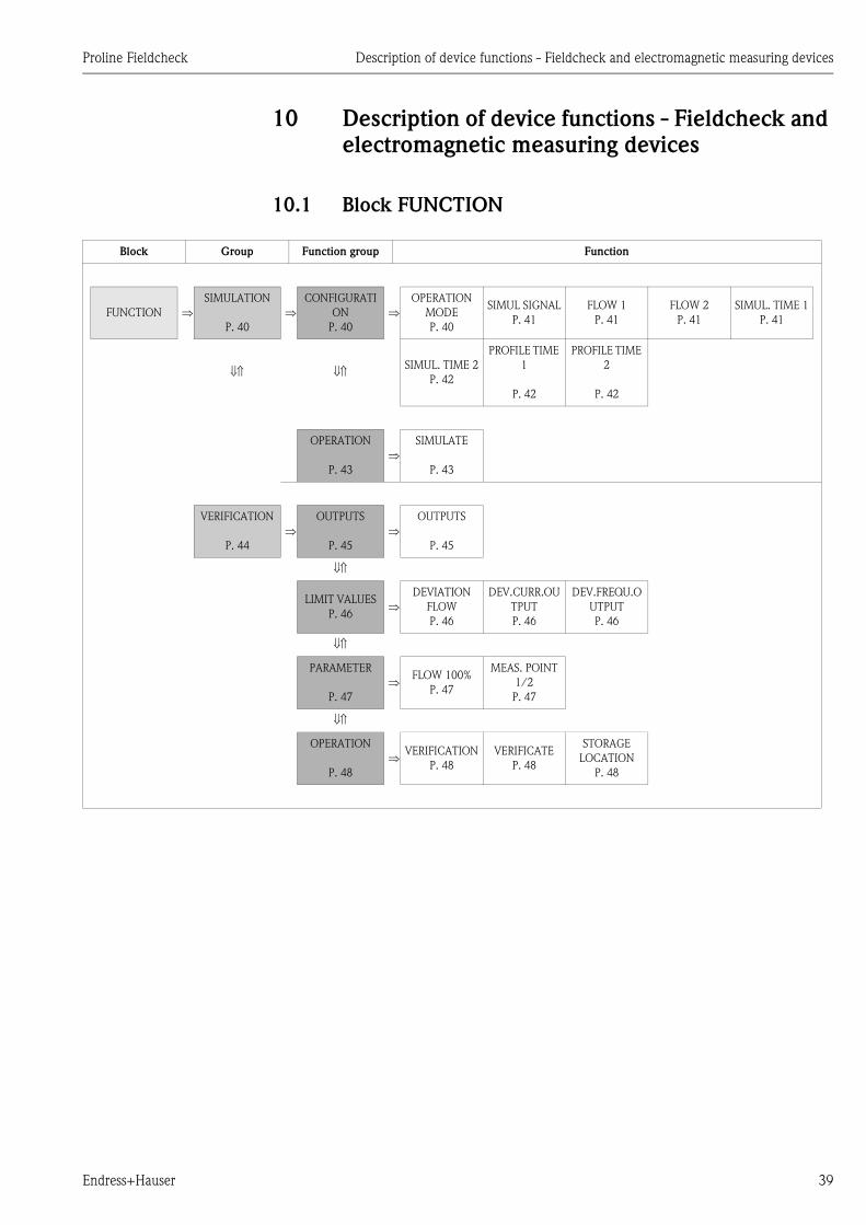
10.1 Block FUNCTION
Block Group Function group Function
FUNCTION ⇒SIMULATION
P. 40
⇒CONFIGURATI
ON
P. 40
⇒OPERATION
MODE
P. 40
SIMUL SIGNAL
P. 41
FLOW 1
P. 41
FLOW 2
P. 41
SIMUL. TIME 1
P. 41
⇓⇑ ⇓⇑SIMUL. TIME 2
P. 42
PROFILE TIME
1
P. 42
PROFILE TIME
2
P. 42
OPERATION
P. 43
⇒SIMULATE
P. 43
VERIFICATION
P. 44
⇒OUTPUTS
P. 45
⇒OUTPUTS
P. 45
⇓⇑
LIMIT VALUES
P. 46⇒
DEVIATION
FLOW
P. 46
DEV.CURR.OU
TPUT
P. 46
DEV.FREQU.O
UTPUT
P. 46
⇓⇑
PARAMETER
P. 47
⇒FLOW 100%
P. 47
MEAS. POINT
1/2
P. 47
⇓⇑
OPERATION
P. 48
⇒VERIFICATION
P. 48
VERIFICATE
P. 48
STORAGE
LOCATION
P. 48
Description of device functions - Fieldcheck and electromagnetic measuring devices Proline Fieldcheck
40 Endress+Hauser
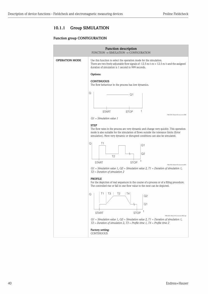
10.1.1 Group SIMULATION
Function group CONFIGURATION
Function descriptionFUNCTION → SIMULATION → CONFIGURATION
OPERATION MODE Use this function to select the operation mode for the simulation.
There are two freely adjustable flow signals of -12.5 m/s to + 12.5 m/s and the assigned
duration of simulation is 1 second to 999 seconds.
Options:
CONTINUOUS
The flow behaviour in the process has low dynamics.
F06-DXC10xxx-05-xx-xx-xx-000
Q1 = Simulation value 1
STEP
The flow rates in the process are very dynamic and change very quickly. This operation
mode is also suitable for the simulation of flows outside the tolerance limits (Error
simulation). Here very dynamic or disrupted conditions can also be simulated.
F06-DXC10xxx-05-xx-xx-xx-001
Q1 = Simulation value 1, Q2 = Simulation value 2, T1 = Duration of simulation 1,
T2 = Duration of simulation 2
PROFILE
For the depiction of real sequences in the course of a process or of a filling procedure.
The controlled rise or fall in one flow value to the next can be depicted.
F06-DXC10xxx-05-xx-xx-xx-002.eps
Q1 = Simulation value 1, Q2 = Simulation value 2, T1 = Duration of simulation 1,
T2 = Duration of simulation 2, T3 = Profile time 1, T4 = Profile time 2
Factory setting:
CONTINUOUS
Q Q1
START STOP t
QQ1
Q2T2
T1
START STOPt
QQ2
Q1
T2T3 T4T1
START STOPt
Proline Fieldcheck Description of device functions - Fieldcheck and electromagnetic measuring devices
Endress+Hauser 41
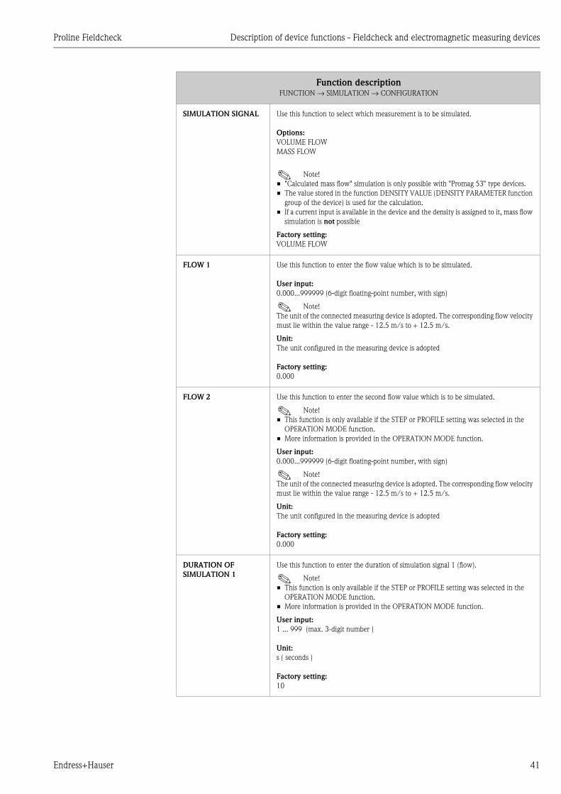
SIMULATION SIGNAL Use this function to select which measurement is to be simulated.
Options:
VOLUME FLOW
MASS FLOW
! Note!
• "Calculated mass flow" simulation is only possible with "Promag 53" type devices.
• The value stored in the function DENSITY VALUE (DENSITY PARAMETER function
group of the device) is used for the calculation.
• If a current input is available in the device and the density is assigned to it, mass flow
simulation is not possible
Factory setting:
VOLUME FLOW
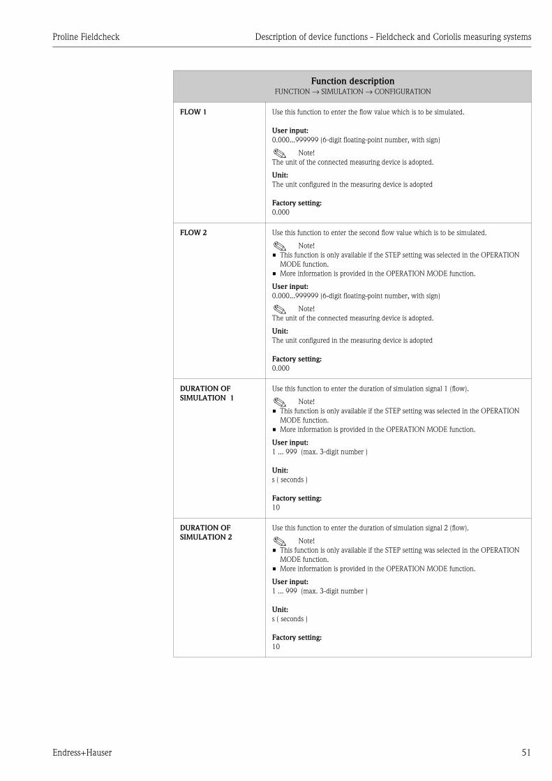
FLOW 1 Use this function to enter the flow value which is to be simulated.
User input:
0.000...999999 (6-digit floating-point number, with sign)
! Note!
The unit of the connected measuring device is adopted. The corresponding flow velocity
must lie within the value range - 12.5 m/s to + 12.5 m/s.
Unit:
The unit configured in the measuring device is adopted
Factory setting:
0.000
FLOW 2 Use this function to enter the second flow value which is to be simulated.
! Note!
• This function is only available if the STEP or PROFILE setting was selected in the
OPERATION MODE function.
• More information is provided in the OPERATION MODE function.
User input:
0.000...999999 (6-digit floating-point number, with sign)
! Note!
The unit of the connected measuring device is adopted. The corresponding flow velocity
must lie within the value range - 12.5 m/s to + 12.5 m/s.
Unit:
The unit configured in the measuring device is adopted
Factory setting:
0.000
DURATION OF
SIMULATION 1
Use this function to enter the duration of simulation signal 1 (flow).
! Note!
• This function is only available if the STEP or PROFILE setting was selected in the
OPERATION MODE function.
• More information is provided in the OPERATION MODE function.
User input:
1 ... 999 (max. 3-digit number )
Unit:
s ( seconds )
Factory setting:
10
Function descriptionFUNCTION → SIMULATION → CONFIGURATION

Description of device functions - Fieldcheck and electromagnetic measuring devices Proline Fieldcheck
42 Endress+Hauser
DURATION OF
SIMULATION 2
Use this function to enter the duration of simulation signal 2 (flow).
! Note!
• This function is only available if the STEP or PROFILE setting was selected in the
OPERATION MODE function.
• More information is provided in the OPERATION MODE function.
User input:
1 ... 999 (max. 3-digit number )
Unit:
s ( seconds )
Factory setting:
10
PROFILE TIME 1 Use this function to enter the period of time for the change from simulation signal 1 to
simulation signal 2.
! Note!
• This function is only available if the PROFILE setting was selected in the OPERATION
MODE function.
• More information is provided in the OPERATION MODE function.
User input:
1 ... 99 (max. 2-digit number)
Unit:
s ( seconds )
Factory setting:
5
PROFILE TIME 2 Use this function to enter the period of time for the change from simulation signal 2 to
simulation signal 1.
! Note!
• This function is only available if the PROFILE setting was selected in the OPERATION
MODE function.
• More information is provided in the OPERATION MODE function.
User input:
1 ... 99 (max. 2-digit number)
Unit:
s ( seconds )
Factory setting:
5
Function descriptionFUNCTION → SIMULATION → CONFIGURATION
Proline Fieldcheck Description of device functions - Fieldcheck and electromagnetic measuring devices
Endress+Hauser 43
Function group OPERATION
Function descriptionFUNCTION → SIMULATION → OPERATION
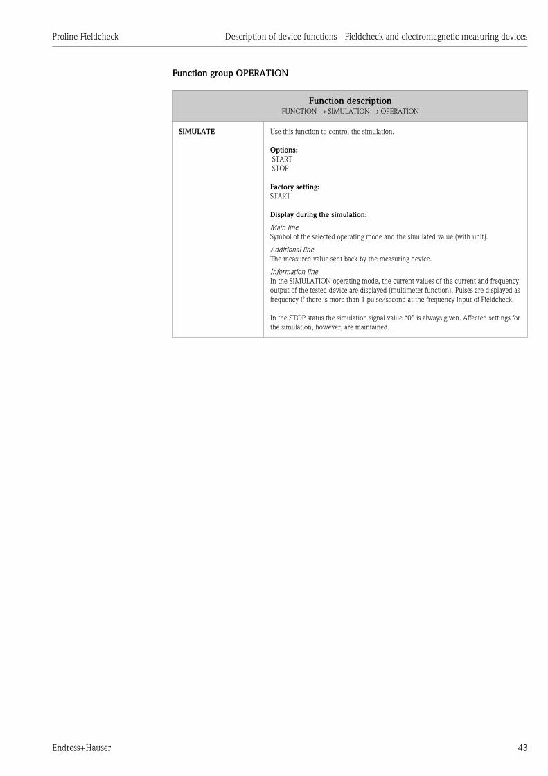
SIMULATE Use this function to control the simulation.
Options:
START
STOP
Factory setting:
START
Display during the simulation:
Main line
Symbol of the selected operating mode and the simulated value (with unit).
Additional line
The measured value sent back by the measuring device.
Information line
In the SIMULATION operating mode, the current values of the current and frequency
output of the tested device are displayed (multimeter function). Pulses are displayed as
frequency if there is more than 1 pulse/second at the frequency input of Fieldcheck.
In the STOP status the simulation signal value “0” is always given. Affected settings for
the simulation, however, are maintained.
Description of device functions - Fieldcheck and electromagnetic measuring devices Proline Fieldcheck
44 Endress+Hauser
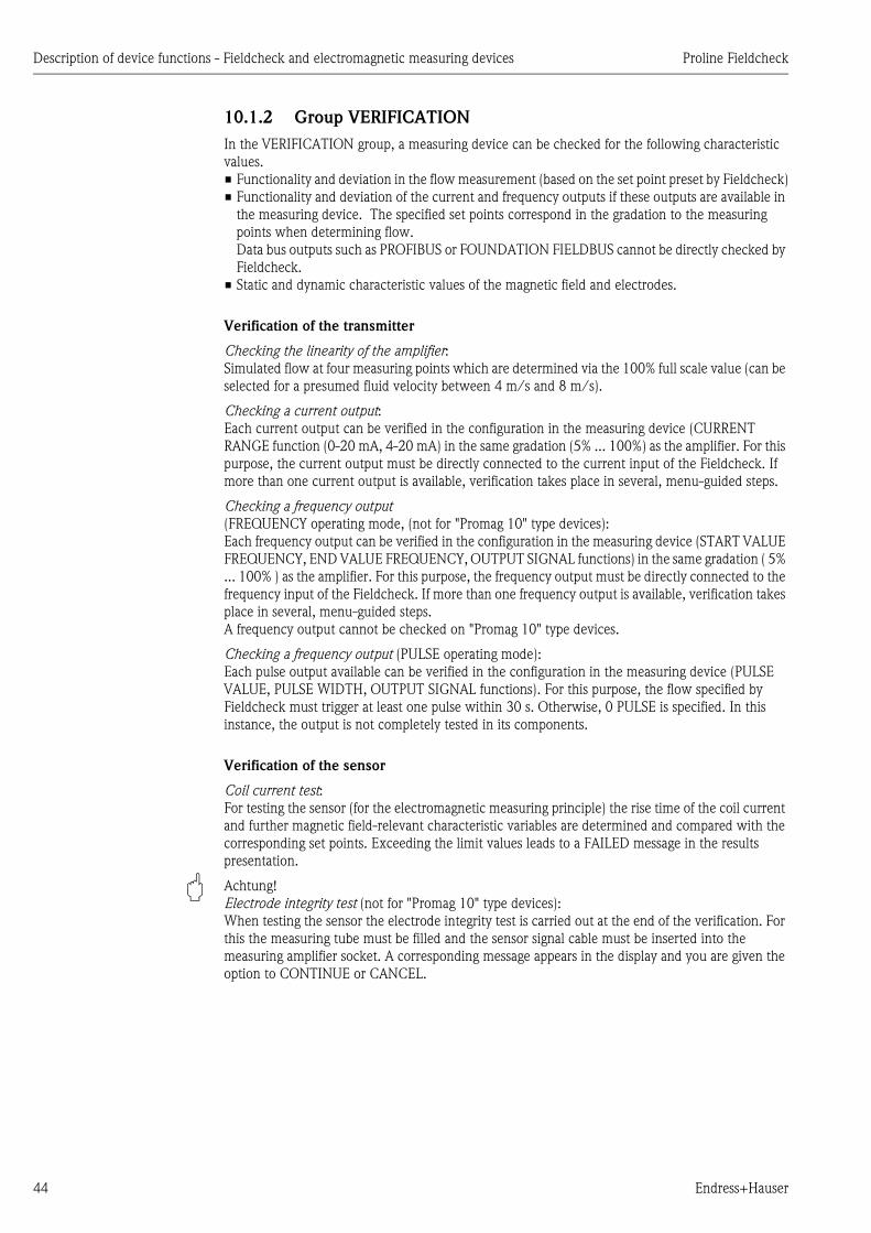
10.1.2 Group VERIFICATION
In the VERIFICATION group, a measuring device can be checked for the following characteristic
values.
• Functionality and deviation in the flow measurement (based on the set point preset by Fieldcheck)
• Functionality and deviation of the current and frequency outputs if these outputs are available in
the measuring device. The specified set points correspond in the gradation to the measuring
points when determining flow.
Data bus outputs such as PROFIBUS or FOUNDATION FIELDBUS cannot be directly checked by
Fieldcheck.
• Static and dynamic characteristic values of the magnetic field and electrodes.
Verification of the transmitter
Checking the linearity of the amplifier:
Simulated flow at four measuring points which are determined via the 100% full scale value (can be
selected for a presumed fluid velocity between 4 m/s and 8 m/s).
Checking a current output:
Each current output can be verified in the configuration in the measuring device (CURRENT
RANGE function (0-20 mA, 4-20 mA) in the same gradation (5% ... 100%) as the amplifier. For this
purpose, the current output must be directly connected to the current input of the Fieldcheck. If
more than one current output is available, verification takes place in several, menu-guided steps.
Checking a frequency output
(FREQUENCY operating mode, (not for "Promag 10" type devices):
Each frequency output can be verified in the configuration in the measuring device (START VALUE
FREQUENCY, END VALUE FREQUENCY, OUTPUT SIGNAL functions) in the same gradation ( 5%
... 100% ) as the amplifier. For this purpose, the frequency output must be directly connected to the
frequency input of the Fieldcheck. If more than one frequency output is available, verification takes
place in several, menu-guided steps.
A frequency output cannot be checked on "Promag 10" type devices.
Checking a frequency output (PULSE operating mode):
Each pulse output available can be verified in the configuration in the measuring device (PULSE
VALUE, PULSE WIDTH, OUTPUT SIGNAL functions). For this purpose, the flow specified by
Fieldcheck must trigger at least one pulse within 30 s. Otherwise, 0 PULSE is specified. In this
instance, the output is not completely tested in its components.
Verification of the sensor
Coil current test:
For testing the sensor (for the electromagnetic measuring principle) the rise time of the coil current
and further magnetic field-relevant characteristic variables are determined and compared with the
corresponding set points. Exceeding the limit values leads to a FAILED message in the results
presentation.
" Achtung!
Electrode integrity test (not for "Promag 10" type devices):
When testing the sensor the electrode integrity test is carried out at the end of the verification. For
this the measuring tube must be filled and the sensor signal cable must be inserted into the
measuring amplifier socket. A corresponding message appears in the display and you are given the
option to CONTINUE or CANCEL.

Proline Fieldcheck Description of device functions - Fieldcheck and electromagnetic measuring devices
Endress+Hauser 45
Evaluation of the results
During verification, the current verification test section is displayed in the 'HOME position'.The
results can be shown on the display once verification is complete. They can be filed in Fieldcheck
under a storage location number of your choice (up to max. 20) together with the measuring device
serial no. and the measuring device tag name.
Via a connection with the FieldTool software, a protocol of the results can later be printed out and
the data from the verification can be stored in an archive file system.
Function group OUTPUTS
During verification, the function and accuracy of a current output and a frequency output can be
checked. Fieldcheck determines the current and frequency outputs available in the measuring
device.
Function descriptionFUNCTION → VERIFICATION → OUTPUTS
OUTPUTS Use this function to display the outputs determined in the flowmeter on the local display
with the related terminals and to select the outputs to be tested. The outputs selected
are displayed inversely.
1. Use the Pkeys to select the outputs which should be tested during the verification
process.
2. Confirm the option selected with the F key.
! Note!
• It is not possible to select two outputs of the same type.
• Start the verification process in the VERIFICATE function (→ Page 48).
Two outputs of the same type are tested in two separate runs. After the 1st run, the
message MORE OUTPUTS TO BE TESTED? appears on the display.
If you want to test other outputs, Fieldcheck returns to the output selection area.
1. Select the output to be tested.
! Note!
Having selected an output, make sure that the related terminal pair of the flowmeter
is connected to the -Fieldcheck input before the verification process is started.
The following combinations of current and frequency outputs are possible for PROline
Promag:
• I
• I+I
• I+F
• I+I+F
• I+F+F
• I+P (only Promag 10)
! Note!
• Fieldbus interfaces cannot be tested.
• With this software-version current outputs run in passive mode cannot be tested.

Description of device functions - Fieldcheck and electromagnetic measuring devices Proline Fieldcheck
46 Endress+Hauser
Function group LIMIT VALUES
You can specify the limit values for measured variables in this function group. If the deviation of a
verification step (see OPERATION, P. 38) lies within the configured limit values the result is
PASSED; if it lies outside of this range the result is FAILED. For a quick and unambiguous
identification, the FAILED results are presented inversely on the display.
! Note!
For a frequency output operated in the pulse mode the fixed error limit is: ± 1 pulse ± 0.1% of the
pulse set number.
Function descriptionFUNCTION → VERIFICATION → LIMIT VALUES
DEVIATION FLOW User input:
0.50 ... 10.0
Unit:
%
Factory setting:
0.5
DEVIATION CURRENT
OUTPUT
This function is only available if a current output was selected in the OUTPUTS function
(→ Page 45).
User input:
0.02...10.0
Unit:
mA
Factory setting:
0.05
DEVIATION
FREQUENCY OUTPUT
This function is only available if a frequency output was selected in the OUTPUTS
function (→ Page 45).
! Note!
This function is not available on "Promag 10" type devices.
User input:
1.0...10.0
Unit:
Hz
Factory setting:
2.00

Proline Fieldcheck Description of device functions - Fieldcheck and electromagnetic measuring devices
Endress+Hauser 47
Function group PARAMETER
Verification of the amplifier takes place along four measuring points MP1...MP4. Use this function
group to enter the full scale value (100%) of the verification flow and the two selectable measuring
points MP2 and MP3 (in % of the full scale value).
! Note!
The value of MP1 is predetermined (5% of the full scale value MP4).
Function descriptionFUNCTION → VERIFICATION → PARAMETER
FLOW 100% Use this function to enter the full scale value of the verification flow.
User input:
max 6-digit floating point number (without sign)
! Note!
Only values between 4 and 8 m/s are permissible. The input limits MIN and MAX are
displayed beyond the input line.
Unit:
The unit configured in the measuring device is adopted
Factory setting:
according 6m/s
MEASURING POINT
2/3
Use this function to enter the measuring points MP2 and MP3 (in % of the full scale
value).
User input:
MP2: integer between 10 and 90
MP3: integer between 15 and 95
! Note!
• The value of MP2 must be less than the value of MP3.
• Both values are stored permanently.
Unit:
%
Factory setting:
MP2: 10 %
MP3: 50%
Description of device functions - Fieldcheck and electromagnetic measuring devices Proline Fieldcheck
48 Endress+Hauser
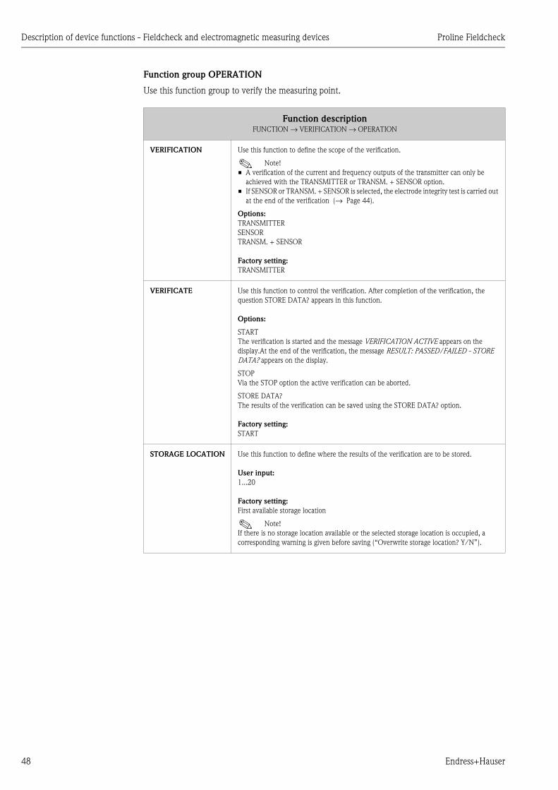
Function group OPERATION
Use this function group to verify the measuring point.
Function descriptionFUNCTION → VERIFICATION → OPERATION
VERIFICATION Use this function to define the scope of the verification.
! Note!
• A verification of the current and frequency outputs of the transmitter can only be
achieved with the TRANSMITTER or TRANSM. + SENSOR option.
• If SENSOR or TRANSM. + SENSOR is selected, the electrode integrity test is carried out
at the end of the verification (→ Page 44).
Options:
TRANSMITTER
SENSOR
TRANSM. + SENSOR
Factory setting:
TRANSMITTER
VERIFICATE Use this function to control the verification. After completion of the verification, the
question STORE DATA? appears in this function.
Options:
START
The verification is started and the message VERIFICATION ACTIVE appears on the
display.At the end of the verification, the message RESULT: PASSED/FAILED - STORE
DATA? appears on the display.
STOP
Via the STOP option the active verification can be aborted.
STORE DATA?
The results of the verification can be saved using the STORE DATA? option.
Factory setting:
START
STORAGE LOCATION Use this function to define where the results of the verification are to be stored.
User input:
1...20
Factory setting:
First available storage location
! Note!
If there is no storage location available or the selected storage location is occupied, a
corresponding warning is given before saving (“Overwrite storage location? Y/N”).

Proline Fieldcheck Description of device functions - Fieldcheck and Coriolis measuring systems
Endress+Hauser 49
11 Description of device functions - Fieldcheck and Coriolis measuring systems
11.1 Block FUNCTION
Block Group Function group Function
FUNCTION ⇒SIMULATION
P. 50
⇒CONFIGURATI
ON
P. 50
⇒OPERATION
MODE
P. 50
SIMUL SIGNAL
P. 50
FLOW 1
P. 51
FLOW 2
P. 51
SIMUL. TIME 1
P. 51
⇓⇑ ⇓⇑SIMUL. TIME 2
P. 51
OPERATION
P. 52
⇒SIMULATE
P. 52
VERIFICATION
P. 53
⇒APPLICAT./OU
TP.
P. 54
⇒FLOW RANGE
P. 54
TYPE UNIT
FLOW
P. 54
OUTPUTS
P. 55
⇓⇑
LIMIT VALUES
P. 56⇒
DEVIATION
FLOW
P. 56
DEVIATION
DENSITY
P. 56
DEVIATION
TEMPERATURE
P. 56
DEVIATION
CURRENT
OUTPUT
P. 56
DEVIATION
FREQU.
OUTPUT
P. 56
⇓⇑
PARAMETER
P. 57
⇒FLOW 100%
P. 57
MEAS. POINT
1/2
P. 57
⇓⇑
OPERATION
P. 58
⇒VERIFICATION
P. 58
VERIFICATE
P. 58
STORAGE
LOCATION
P. 58

Description of device functions - Fieldcheck and Coriolis measuring systems Proline Fieldcheck
50 Endress+Hauser
11.1.1 Group SIMULATION
Function group CONFIGURATION
Function descriptionFUNCTION → SIMULATION → CONFIGURATION
OPERATION MODE Use this function to select the operation mode for the simulation.
There are two freely adjustable flow signals of -12.5 m/s to + 12.5 m/s and the assigned
duration of simulation is 1 second to 999 seconds.
Options:
CONTINUOUS
The flow behaviour in the process has low dynamics.
F06-DXC10xxx-05-xx-xx-xx-000
Q1 = Simulation value 1
STEP
The flow rates in the process are very dynamic and change very quickly. This operation
mode is also suitable for the simulation of flows outside the tolerance limits (Error
simulation). Here very dynamic or disrupted conditions can also be simulated.
F06-DXC10xxx-05-xx-xx-xx-001
Q1 = Simulation value 1, Q2 = Simulation value 2, T1 = Duration of simulation 1,
T2 = Duration of simulation 2
Factory setting:
CONTINUOUS
SIMULATION SIGNAL Use this function to select which measurement is to be simulated.
Options:
MASS FLOW
VOLUME FLOW
CORRECTED VOLUME FLOW (not for Promass 40)
! Note!
• The option CORRECTED VOLUME FLOW is only available if the
FIXED REFERENCE DENSITY option was selected in the CORRECTED VOLUME
CALCULATION function in the tested device.
• For the simulation of corrected volume flow, the system uses the values specified by
the flowmeter in the REFERENCE DENSITY and UNIT REFERENCE DENSITY
functions.
Factory setting:
MASS FLOW
Q Q1
START STOP t
QQ1
Q2T2
T1
START STOPt
Proline Fieldcheck Description of device functions - Fieldcheck and Coriolis measuring systems
Endress+Hauser 51
FLOW 1 Use this function to enter the flow value which is to be simulated.
User input:
0.000...999999 (6-digit floating-point number, with sign)
! Note!
The unit of the connected measuring device is adopted.
Unit:
The unit configured in the measuring device is adopted
Factory setting:
0.000
FLOW 2 Use this function to enter the second flow value which is to be simulated.
! Note!
• This function is only available if the STEP setting was selected in the OPERATION
MODE function.
• More information is provided in the OPERATION MODE function.
User input:
0.000...999999 (6-digit floating-point number, with sign)
! Note!
The unit of the connected measuring device is adopted.
Unit:
The unit configured in the measuring device is adopted
Factory setting:
0.000
DURATION OF
SIMULATION 1
Use this function to enter the duration of simulation signal 1 (flow).
! Note!
• This function is only available if the STEP setting was selected in the OPERATION
MODE function.
• More information is provided in the OPERATION MODE function.
User input:
1 ... 999 (max. 3-digit number )
Unit:
s ( seconds )
Factory setting:
10
DURATION OF
SIMULATION 2
Use this function to enter the duration of simulation signal 2 (flow).
! Note!
• This function is only available if the STEP setting was selected in the OPERATION
MODE function.
• More information is provided in the OPERATION MODE function.
User input:
1 ... 999 (max. 3-digit number )
Unit:
s ( seconds )
Factory setting:
10
Function descriptionFUNCTION → SIMULATION → CONFIGURATION

Description of device functions - Fieldcheck and Coriolis measuring systems Proline Fieldcheck
52 Endress+Hauser
Function group OPERATION
Function descriptionFUNCTION → SIMULATION → OPERATION
SIMULATE Use this function to control the simulation.
Options:
START
STOP
Factory setting:
START
Display during the simulation:
Main line
Symbol of the selected operating mode and the simulated value (with unit).
Additional line
The measured value sent back by the measuring device.
Information line
In the SIMULATION operating mode, the current values of the current and frequency
output of the tested device are displayed (multimeter function). Pulses are displayed as
frequency if there is more than 1 pulse/second at the frequency input of Fieldcheck.
In the STOP status the simulation signal value “0” is always given. Affected settings for
the simulation, however, are maintained.

Proline Fieldcheck Description of device functions - Fieldcheck and Coriolis measuring systems
Endress+Hauser 53
11.1.2 Group VERIFICATION
In the VERIFICATION group, a measuring device can be checked for the following characteristic
values.
• Functionality and deviation in the flow measurement (based on the set point preset by Fieldcheck)
• Functionality and deviation of the current and frequency outputs if these outputs are available in
the measuring device. The specified set points correspond in the gradation to the measuring
points when determining flow.
Data bus outputs such as PROFIBUS or FOUNDATION FIELDBUS cannot be directly checked by
FieldCheck.
• Characteristic values from internal tests for the sensor part.
Verification of the transmitter
Checking the linearity of the amplifier:
Simulated flow at four measuring points which are determined via the 100% full scale value. The
mass flow is verified using a constant density of 1.0kg/l. The presumed fluid velocity is 4...8m/s
for the standard range and 0.4...0.8m/s for the low range.
Checking a current output:
Each current output can be verified in the configuration in the measuring device (CURRENT
RANGE function ( 0-20 mA, 4-20 mA) in the same gradation (5% ... 100%) as the amplifier. For this
purpose, the current output must be directly connected to the current input of the Fieldcheck. If
more than one current output is available, verification takes place in several, menu-guided steps.
Checking a frequency output (FREQUENCY operating mode) :
Each frequency output can be verified in the configuration in the measuring device (START VALUE
FREQUENCY, END VALUE FREQUENCY, OUTPUT SIGNAL functions) in the same gradation ( 5%
... 100% ) as the amplifier. For this purpose, the frequency output must be directly connected to the
frequency input of the Fieldcheck. If more than one frequency output is available, verification takes
place in several, menu-guided steps.
Checking a frequency output (PULSE operating mode):
Each pulse output available can be verified in the configuration in the measuring device (PULSE
VALUE, PULSE WIDTH, OUTPUT SIGNAL functions). For this purpose, the flow specified by
Fieldcheck must trigger at least one pulse within 30 s. Otherwise, 0 PULSE is specified. In this
instance, the output is not completely tested in its components.
Verification of the sensor circuits
A series of internal tests are run through for checking the sensor connections and the closed-control
loops of excitation current and frequency with plugs connected for the excitation current and
amplifier. A PASSED or FAILED is output as a result.
The test series are combined into four groups for the result output:
• Excitation circuit
• Frequency parameters
• Temperature measuring points
• Pick-up coils
! Note!
One of the following options must be selected in the VERIFICATION function (→ Page 58) to carry
out the test series:
• TRANSMITTER + SENSOR
• SENSOR
Evaluation of the results
During verification, the current verification test section is displayed in the 'HOME position'. The
results can be shown on the display once verification is complete. They can be filed in Fieldcheck
under a storage location number of your choice (up to max. 20) together with the measuring device
serial no. and the measuring device tag name.

Description of device functions - Fieldcheck and Coriolis measuring systems Proline Fieldcheck
54 Endress+Hauser
Via a connection with the FieldTool software, a protocol of the results can later be printed out and
the data from the verification can be stored in an archive file system.
Function group APPLICATION/OUTPUTS
During verification, the function and accuracy of a current output and a frequency output can be
checked. Fieldcheck determines the current and frequency outputs available in the measuring
device.
Function descriptionFUNCTION → VERIFICATION → APPLICATION/OUTPUTS
FLOW RANGE Use this function to select the amplifier verification range suitable for the application in
question.
Options:
STANDARD RANGE:
Flow range of the original factory calibration.
LOW RANGE:
Compared to the standard range, the flow range has dropped by a factor of 10.
" Caution!
If the LOW RANGE option is selected, the smallest permissible limit value (error limit)
in the DEVIATION FLOW function (→ Page 56) is higher than in the STANDARD
RANGE option.
Factory setting:
STANDARD RANGE
TYPE UNIT FLOW Use this function to select the unit type for the verification of the amplifier.
Options:
MASS FLOW
CORRECTED VOLUME FLOW (not available for Promass 40)
! Note!
The option CORRECTED VOLUME FLOW is only available if the FIXED REFERENCE
DENSITY option was selected in the CORRECTED VOLUME CALCULATION function
in the tested device.
Factory setting:
MASS FLOW
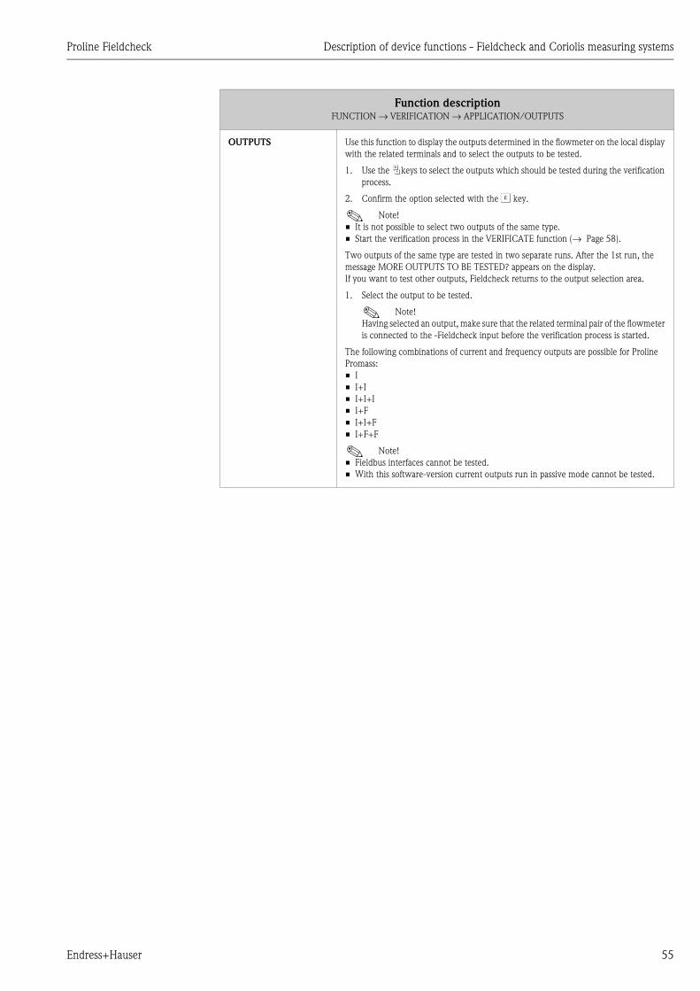
Proline Fieldcheck Description of device functions - Fieldcheck and Coriolis measuring systems
Endress+Hauser 55
OUTPUTS Use this function to display the outputs determined in the flowmeter on the local display
with the related terminals and to select the outputs to be tested.
1. Use the Pkeys to select the outputs which should be tested during the verification
process.
2. Confirm the option selected with the F key.
! Note!
• It is not possible to select two outputs of the same type.
• Start the verification process in the VERIFICATE function (→ Page 58).
Two outputs of the same type are tested in two separate runs. After the 1st run, the
message MORE OUTPUTS TO BE TESTED? appears on the display.
If you want to test other outputs, Fieldcheck returns to the output selection area.
1. Select the output to be tested.
! Note!
Having selected an output, make sure that the related terminal pair of the flowmeter
is connected to the -Fieldcheck input before the verification process is started.
The following combinations of current and frequency outputs are possible for Proline
Promass:
• I
• I+I
• I+I+I
• I+F
• I+I+F
• I+F+F
! Note!
• Fieldbus interfaces cannot be tested.
• With this software-version current outputs run in passive mode cannot be tested.
Function descriptionFUNCTION → VERIFICATION → APPLICATION/OUTPUTS

Description of device functions - Fieldcheck and Coriolis measuring systems Proline Fieldcheck
56 Endress+Hauser
Function group LIMIT VALUES
You can specify the limit values for measured variables in this function group. If the deviation of a
verification step (see OPERATION, P. 38) lies within the configured limit values the result is
PASSED; if it lies outside of this range the result is FAILED. For a quick and unambiguous
identification, the FAILED results are presented inversely on the display.
Function descriptionFUNCTION → VERIFICATION → LIMIT VALUES
DEVIATION FLOW User input:
0.30...10.00 (for Promass 80/83 with sensors A, F, M)
0.50...10.00 (for Promass 80/83 with sensors E, H, I and Promass 40)
5.00...10.00 (if LOW RANGE is selected in the FLOW RANGE function, see Page 54)
Unit:
%
Factory setting:
0.5 or 5.0
DEVIATION DENSITY User input:
0.50 ... 10.00
Unit:
%
Factory setting:
0.5
DEVIATION
TEMPERATURE
User input:
1.00...10.00 (for the units °C and K)
2.00...10.00 (for the units °F and R)
Unit:
The unit configured in the measuring device is adopted
Factory setting:
2.0 (for the units °C and K)
4.0 (for the units °F and R)
DEVIATION CURRENT
OUTPUT
This function is only available if a current output was selected in the OUTPUTS function
(→ Page 55).
User input:
0.02...10.0
Unit:
mA
Factory setting:
0.05
DEVIATION
FREQUENCY OUTPUT
This function is only available if a frequency output was selected in the OUTPUTS
function (→ Page 55).
User input:
1.0...10.0
Unit:
Hz
Factory setting:
2.00
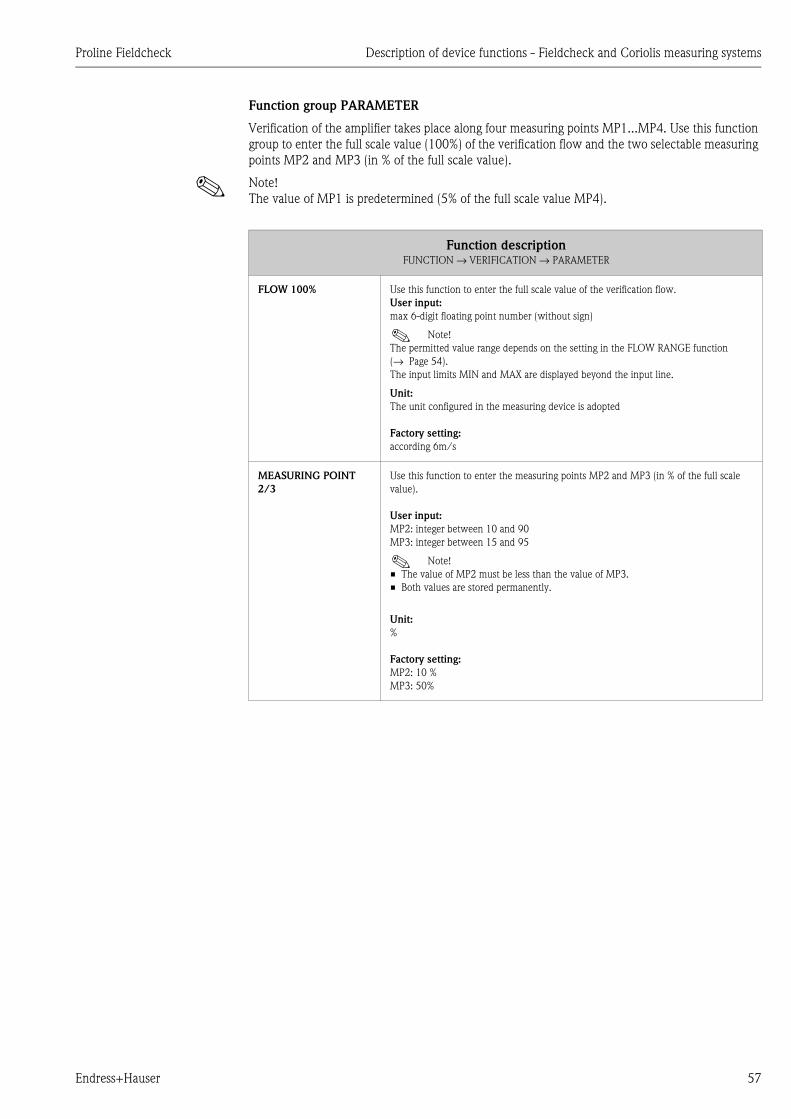
Proline Fieldcheck Description of device functions - Fieldcheck and Coriolis measuring systems
Endress+Hauser 57
Function group PARAMETER
Verification of the amplifier takes place along four measuring points MP1...MP4. Use this function
group to enter the full scale value (100%) of the verification flow and the two selectable measuring
points MP2 and MP3 (in % of the full scale value).
! Note!
The value of MP1 is predetermined (5% of the full scale value MP4).
Function descriptionFUNCTION → VERIFICATION → PARAMETER
FLOW 100% Use this function to enter the full scale value of the verification flow.
User input:
max 6-digit floating point number (without sign)
! Note!
The permitted value range depends on the setting in the FLOW RANGE function
(→ Page 54).
The input limits MIN and MAX are displayed beyond the input line.
Unit:
The unit configured in the measuring device is adopted
Factory setting:
according 6m/s
MEASURING POINT
2/3
Use this function to enter the measuring points MP2 and MP3 (in % of the full scale
value).
User input:
MP2: integer between 10 and 90
MP3: integer between 15 and 95
! Note!
• The value of MP2 must be less than the value of MP3.
• Both values are stored permanently.
Unit:
%
Factory setting:
MP2: 10 %
MP3: 50%

Description of device functions - Fieldcheck and Coriolis measuring systems Proline Fieldcheck
58 Endress+Hauser
Function group OPERATION
Use this function group to specify the scope of the verification and to start/stop the verification.
Function descriptionFUNCTION → VERIFICATION → OPERATION
VERIFICATION Use this function to define the scope of the test.
! Note!
A verification of the current and frequency outputs of the transmitter can only be achieved
with the TRANSMITTER or TRANSM. + SENSOR option.
Options:
TRANSMITTER:
The meter electronics and the electronics of the current and frequency outputs selected
are tested. Excitation current cable and sensor signal cable are plugged out.
SENSOR
The temperature measuring points, the closed-control loops of the excitation current and
frequency and the pick-up coils are tested. Excitation current cable and sensor signal cable
are plugged in.
TRANSM. + SENSOR
All test groups are run through. At the end of the transmitter test, you are requested to
reconnect the excitation current cable and sensor signal cable.
Factory setting:
TRANSMITTER
VERIFICATE Use this function to control the verification. After completion of the verification, the
question STORE DATA? appears in this function.
Options:
START
The verification is started and the message VERIFICATION ACTIVE appears on the
display.At the end of the verification, the message RESULT: PASSED/FAILED - STORE
DATA? appears on the display.
STOP
Via the STOP option the active verification can be aborted.
STORE DATA?
The results of the verification can be saved using the STORE DATA? option.
Factory setting:
START
STORAGE LOCATION Use this function to define where the results of the verification are to be stored.
User input:
1...20
Factory setting:
First available storage location
! Note!
If there is no storage location available or the selected storage location is occupied, a
corresponding warning is given before saving (“Overwrite storage location? Y/N”).

Proline Fieldcheck Description of device functions - Fieldcheck and vortex measuring systems
Endress+Hauser 59
12 Description of device functions - Fieldcheck and vortex measuring systems
12.1 Block FUNCTION
Block Group Function group Function
FUNCTION ⇒SIMULATION
P. 60
⇒CONFIGURATI
ON
P. 60
⇒
OPERATION
MODE
P. 60
SIMUL.
SIGNAL
P. 60
FLOW 1
P. 61
FLOW 2
P. 61
SIMUL. TIME 1
P. 61
⇓⇑ ⇓⇑SIMUL. TIME 2
P. 61
CONFIGURATI
ON
P. 62
SIMULATE
P. 61
VERIFICATION
P. 63
OUTPUTS
P. 64
OUTPUTS
P. 64
⇓⇑
LIMIT
VALUESP. 65
DEVIATION
FLOW
P. 65
DEV.CURR.OU
TPUT
P. 65
⇓⇑
PARAMETER
P. 66
FLOW 100%
P. 66
MEAS. POINT
1/2
P. 66
⇓⇑
OPERATION
P. 67
VERIFICATION
P. 67
VERIFICATE
P. 67
STORAGE
LOCATION
P. 67

Description of device functions - Fieldcheck and vortex measuring systems Proline Fieldcheck
60 Endress+Hauser
12.1.1 Group SIMULATION
Please note the following:
• In contrast to electromagnetic or Coriolis measuring devices, a gap-free flow range 0 - Qmax
cannot be simulated with vortex flowmeters. Below a certain fluid speed (approx. 0.15 m/s for
water), the amplitude of the vortex signal becomes so small that it is no longer possible to record
the measured value. For this reason, when setting the simulated flow, the values 0, the smallest
flow Qmin and the largest flow Qmax are displayed.
• The flow value actually simulated can deviate slightly from the value entered in the FLOW 1/2
function. The value actually simulated is displayed on the first line in the HOME position of the
Fieldcheck local display.
Function group CONFIGURATION
Function descriptionFUNCTION → SIMULATION → CONFIGURATION
OPERATION MODE Use this function to select the operation mode for the simulation.
The following signals can be freely configured:
• Operation mode GAS/STEAM: 0, Qmin...70 m/s
• Operation mode LIQUID: 0, Qmin...9 m/s
Options:
CONTINUOUS
The flow behaviour in the process has low dynamics.
F06-DXC10xxx-05-xx-xx-xx-000
Q1 = Simulation value 1
STEP
The flow rates in the process are very dynamic and change very quickly. This operation
mode is also suitable for the simulation of flows outside the tolerance limits (Error
simulation). Here very dynamic or disrupted conditions can also be simulated.
F06-DXC10xxx-05-xx-xx-xx-001
Q1 = Simulation value 1, Q2 = Simulation value 2, T1 = Duration of simulation 1,
T2 = Duration of simulation 2
SIMULATION SIGNAL Use this function to view the set simulation signal in the measuring device.
Display:
VOLUME FLOW
CALCULATED MASS FLOW
CALCULATED CORRECTED VOLUME FLOW
! Note!
• For the simulation of a calculated mass flow, the system uses the value specified by
the flowmeter in the OPERATING DENSITY function.
• For the simulation of corrected volume flow, the system uses the values specified by
the flowmeter in the OPERATING DENSITY and REFERENCE DENSITY functions.
Q Q1
START STOP t
QQ1
Q2T2
T1
START STOPt

Proline Fieldcheck Description of device functions - Fieldcheck and vortex measuring systems
Endress+Hauser 61
FLOW 1 Use this function to specify the first flow value which is to be simulated.
User input:
0.000...99999 (6-digit floating-point number)
! Note!
The flow limits are adopted depending on the option selected in the APPLICATION
function of the flowmeter. Values smaller than Qmin cannot be entered (→ Page 60).
They have the following values:
• GAS/STEAM: 0, Qmin...70 m/s
• LIQUID: 0, Qmin...9 m/s
Unit:
The unit configured in the measuring device is adopted
Factory setting:
0.000
FLOW 2 Use this function to enter the second flow value which is to be simulated.
! Note!
• This function is only available if the STEP setting was selected in the OPERATION
MODE function.
• More information is provided in the OPERATION MODE function.
• The flow limits are adopted depending on the option selected in the APPLICATION
function of the flowmeter. Values smaller than Qmin cannot be entered
(→ Page 60). They have the following values:
– GAS/STEAM: 0, Qmin...70 m/s
– LIQUID: 0, Qmin...9 m/s
User input:
0.000...99999 (6-digit floating-point number)
Unit:
The unit configured in the measuring device is adopted
Factory setting:
0.000
DURATION OF
SIMULATION 1
Use this function to enter the duration of simulation signal 1 (flow).
! Note!
• This function is only available if the STEP setting was selected in the OPERATION
MODE function.
• More information is provided in the OPERATION MODE function.
User input:
1 ... 999 (max. 3-digit number )
Unit:
s ( seconds )
Factory setting:
10
DURATION OF
SIMULATION 2
Use this function to enter the duration of simulation signal 2 (flow).
! Note!
• This function is only available if the STEP setting was selected in the OPERATION
MODE function.
• More information is provided in the OPERATION MODE function.
User input:
1 ... 999 (max. 3-digit number )
Unit:
s ( seconds )
Factory setting:
10
Function descriptionFUNCTION → SIMULATION → CONFIGURATION
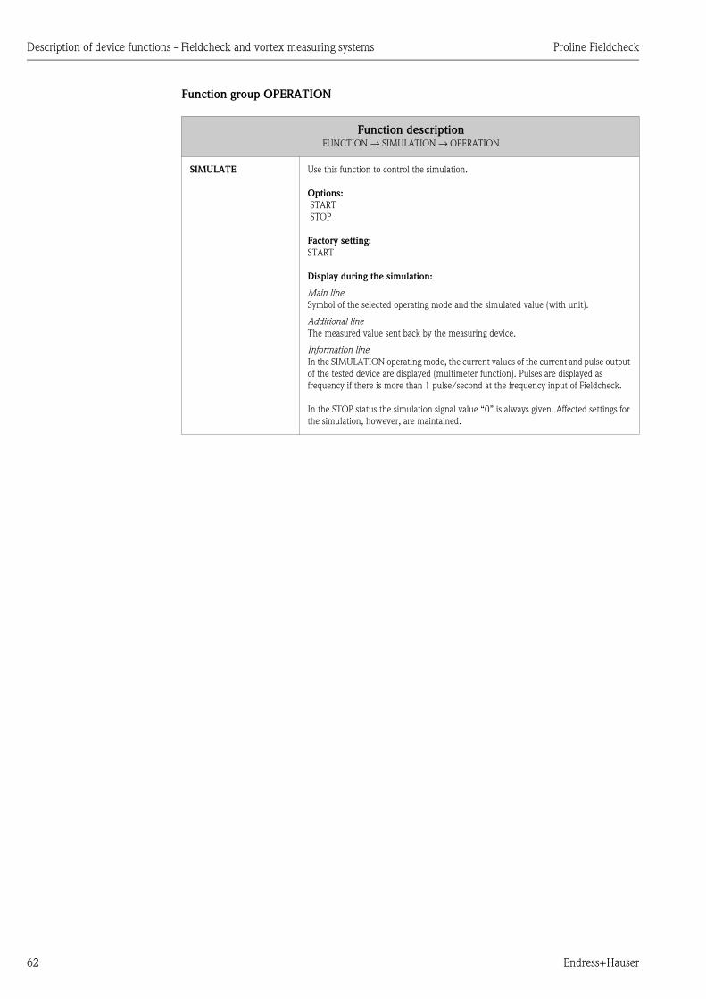
Description of device functions - Fieldcheck and vortex measuring systems Proline Fieldcheck
62 Endress+Hauser
Function group OPERATION
Function descriptionFUNCTION → SIMULATION → OPERATION
SIMULATE Use this function to control the simulation.
Options:
START
STOP
Factory setting:
START
Display during the simulation:
Main line
Symbol of the selected operating mode and the simulated value (with unit).
Additional line
The measured value sent back by the measuring device.
Information line
In the SIMULATION operating mode, the current values of the current and pulse output
of the tested device are displayed (multimeter function). Pulses are displayed as
frequency if there is more than 1 pulse/second at the frequency input of Fieldcheck.
In the STOP status the simulation signal value “0” is always given. Affected settings for
the simulation, however, are maintained.
Proline Fieldcheck Description of device functions - Fieldcheck and vortex measuring systems
Endress+Hauser 63
12.1.2 Group VERIFICATION
In the VERIFICATION group, a measuring device can be checked for the following characteristic
values.
• Functionality and deviation in the flow measurement (based on the set point preset by Fieldcheck)
• Functionality and deviation of the current output and optional pulse output if these outputs are
available in the measuring device. The specified set points correspond in the gradation to the
measuring points when determining flow.
Fieldbus outputs such as PROFIBUS or FOUNDATION FIELDBUS cannot be directly checked by
Fieldcheck.
! Note!
The device can be tested at its mounting location; power is supplied by the switching unit
connected to the current output. In order to test the current output for accuracy at the mounting
location, it must be disconnected from the switching unit and connected to the Fieldcheck
current input.
Verification of the transmitter
Checking the linearity of the amplifier:
Simulated flow at four measuring points which are determined via the 100% full scale value (for a
presumed fluid velocity of 8 m/s for liquids and 60 m/s for gases/steam).
Checking the current output:
The current output can be verified in the configuration in the measuring device (CURRENT RANGE
function (0-20 mA, 4-20 mA) in the same gradation (5% ... 100%) as the amplifier. For this purpose,
the current output must be directly connected to the current input of the Fieldcheck.
Checking the pulse output:
An existing pulse output can be verified in the configuration in the measuring device (PULSE
VALUE, PULSE WIDTH, OUTPUT SIGNAL functions). For this purpose, the pulse output must be
directly connected to the frequency input of the Fieldcheck.
Evaluation of the results
During verification, the current verification test section is displayed in the 'HOME position'. The
results can be shown on the display once verification is complete. They can be filed in FieldCheck
under a storage location number of your choice (up to max. 20) together with the measuring device
serial no. and the measuring device tag name.
Via a connection with the FieldTool software, a protocol of the results can later be printed out and
the data from the verification can be stored in an archive file system.

Description of device functions - Fieldcheck and vortex measuring systems Proline Fieldcheck
64 Endress+Hauser
Function group OUTPUTS
During verification, the function and accuracy of the current output and the optional pulse output
can be checked. Fieldcheck determines the outputs available in the measuring device.
Function descriptionFUNCTION → VERIFICATION → OUTPUTS
OUTPUTS Use this function to display the outputs determined in the flowmeter on the local display
with the related terminals and to select the outputs to be tested.
1. Use the Pkeys to select the outputs which should be tested during the verification
process.
2. Confirm the option selected with the Fkey.
! Note!
Start the verification process in the VERIFICATE function (→ Page 67).
The following combinations are possible for Proline Prowirl:
• I
• I+P
! Note!
Fieldbus interfaces cannot be tested.

Proline Fieldcheck Description of device functions - Fieldcheck and vortex measuring systems
Endress+Hauser 65
Function group LIMIT VALUES
You can specify the limit values for measured variables in this function group. If the deviation of a
verification step (see OPERATION, P. 38) lies within the configured limit values the result is
PASSED; if it lies outside of this range the result is FAILED. For a quick and unambiguous
identification, the FAILED results are presented inversely on the display.
Function descriptionFUNCTION → VERIFICATION → LIMIT VALUES
DEVIATION FLOW
(when measuring
liquids)
User input:
1.50...10.00
Unit:
%
Factory setting:
1.5
DEVIATION FLOW
(when measuring gas or
steam)
User input:
2.0...10.00
Unit:
%
Factory setting:
2.0
DEVIATION CURRENT
OUTPUT
This function is only available if the current output was selected in the OUTPUTS
function (→ Page 64).
User input:
0.02...1.00
Unit:
mA
Factory setting:
0.05

Description of device functions - Fieldcheck and vortex measuring systems Proline Fieldcheck
66 Endress+Hauser
Function group PARAMETER
Verification of the amplifier takes place along four measuring points MP1...MP4. Use this function
group to enter the two selectable measuring points MP2 and MP3 (in % of the full scale value).
! Note!
The value of MP1 is predetermined (5% of the full scale value MP4).
Function descriptionFUNCTION → VERIFICATION → PARAMETER
FLOW 100% Use this function to display the full scale value of the verification flow.
In liquid applications, the 100% value usually corresponds to a fluid velocity of 8 m/s
and a velocity of 60 m/s in gas/steam applications.
MEASURING POINT
2/3
Use this function to enter the measuring points MP2 and MP3 (in % of the full scale
value).
User input:
MP2: integer between 10 and 90
MP3: integer between 15 and 95
! Note!
• The value of MP2 must be less than the value of MP3.
• Both values are stored permanently.
• In demanding measuring applications, the usable measuring range of the vortex
measuring device can be restricted to such an extent that the lower MP1 verification
measuring point cannot achieve the 5% value. In this instance, the minimum which
can be achieved of the measurable flow is determined and calculated as a % value of
the maximum value MP 4 and displayed. MP2 and MP3 are then determined again
as default values and displayed. However, they are not saved when the work with
Fieldcheck is completed.
Unit:
%
Factory setting:
MP2: 10 %
MP3: 50%

Proline Fieldcheck Description of device functions - Fieldcheck and vortex measuring systems
Endress+Hauser 67
Function group OPERATION
Use this function group to specify the scope of the verification and to start/stop the verification.
Function descriptionFUNCTION → VERIFICATION → OPERATION
VERIFICATION Use this function to define the scope of the test.
Options:
TRANSMITTER
SENSOR
TRANSMITTER + SENSOR
Factory setting:
TRANSMITTER
VERIFICATE Use this function to control the verification. After completion of the verification, the
question STORE DATA? appears in this function.
Options:
START
The verification is started and the message VERIFICATION ACTIVE appears on the
display.At the end of the verification, the message RESULT: PASSED/FAILED - STORE
DATA? appears on the display.
STOP
Via the STOP option the active verification can be aborted.
STORE DATA?
The results of the verification can be saved using the STORE DATA? option.
Factory setting:
START
STORAGE LOCATION Use this function to define where the results of the verification are to be stored.
User input:
1...20
Factory setting:
First available storage location
! Note!
If there is no storage location available or the selected storage location is occupied, a
corresponding warning is given before saving (“Overwrite storage location? Y/N”).
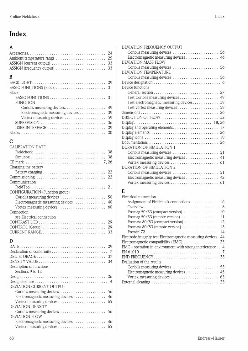
Proline Fieldcheck Index
68 Endress+Hauser
Index
AAccessories. . . . . . . . . . . . . . . . . . . . . . . . . . . . . . . . . . . . 24
Ambient temperature range . . . . . . . . . . . . . . . . . . . . . . . 25
ASSIGN (current output) . . . . . . . . . . . . . . . . . . . . . . . . . 33
ASSIGN (frequency output) . . . . . . . . . . . . . . . . . . . . . . . 33
BBACK LIGHT . . . . . . . . . . . . . . . . . . . . . . . . . . . . . . . . . . 29
BASIC FUNCTIONS (Block) . . . . . . . . . . . . . . . . . . . . . . . 31
Block
BASIC FUNCTIONS . . . . . . . . . . . . . . . . . . . . . . . . . . 31
FUNCTION
Coriolis measuring devices. . . . . . . . . . . . . . . . . . . 49
Electromagnetic measuring devices . . . . . . . . . . . . 39
Vortex measuring devices . . . . . . . . . . . . . . . . . . . 59
SUPERVISION . . . . . . . . . . . . . . . . . . . . . . . . . . . . . . 36
USER INTERFACE . . . . . . . . . . . . . . . . . . . . . . . . . . . 29
Blocks . . . . . . . . . . . . . . . . . . . . . . . . . . . . . . . . . . . . . . . 20
CCALIBRATION DATE
Fieldcheck . . . . . . . . . . . . . . . . . . . . . . . . . . . . . . . . . 38
Simubox . . . . . . . . . . . . . . . . . . . . . . . . . . . . . . . . . . . 38
CE mark . . . . . . . . . . . . . . . . . . . . . . . . . . . . . . . . . . . 7, 26
Charging the battery
Battery charging . . . . . . . . . . . . . . . . . . . . . . . . . . . . . 22
Commissioning . . . . . . . . . . . . . . . . . . . . . . . . . . . . . . . . 22
Communication
FieldTool . . . . . . . . . . . . . . . . . . . . . . . . . . . . . . . . . . 21
CONFIGURATION (Function group)
Coriolis measuring devices . . . . . . . . . . . . . . . . . . . . . 50
Electromagnetic measuring devices . . . . . . . . . . . . . . . 40
Vortex measuring devices . . . . . . . . . . . . . . . . . . . . . . 60
Connection
see Electrical connection
CONTRAST LCD . . . . . . . . . . . . . . . . . . . . . . . . . . . . . . . 29
CONTROL (Group) . . . . . . . . . . . . . . . . . . . . . . . . . . . . . 29
CURRENT RANGE. . . . . . . . . . . . . . . . . . . . . . . . . . . . . . 33
DDATE. . . . . . . . . . . . . . . . . . . . . . . . . . . . . . . . . . . . . . . . 29
Declaration of conformity . . . . . . . . . . . . . . . . . . . . . . . . . . 7
DEL. STORAGE . . . . . . . . . . . . . . . . . . . . . . . . . . . . . . . . 37
DENSITY VALUE . . . . . . . . . . . . . . . . . . . . . . . . . . . . . . . 34
Description of functions
Sections 9 to 12
Design . . . . . . . . . . . . . . . . . . . . . . . . . . . . . . . . . . . . . . . 26
Designated use . . . . . . . . . . . . . . . . . . . . . . . . . . . . . . . . . . 4
DEVIATION CURRENT OUTPUT
Coriolis measuring devices . . . . . . . . . . . . . . . . . . . . . 56
Electromagnetic measuring devices . . . . . . . . . . . . . . . 46
Vortex measuring devices . . . . . . . . . . . . . . . . . . . . . . 65
DEVIATION DENSITY
Coriolis measuring devices . . . . . . . . . . . . . . . . . . . . . 56
DEVIATION FLOW
Electromagnetic measuring devices . . . . . . . . . . . . . . . 46
Vortex measuring devices . . . . . . . . . . . . . . . . . . . . . . 65
DEVIATION FREQUENCY OUTPUT
Coriolis measuring devices . . . . . . . . . . . . . . . . . . . . . 56
Electromagnetic measuring devices . . . . . . . . . . . . . . . 46
DEVIATION MASS FLOW
Coriolis measuring devices . . . . . . . . . . . . . . . . . . . . . 56
DEVIATION TEMPERATURE
Coriolis measuring devices . . . . . . . . . . . . . . . . . . . . . 56
Device designation . . . . . . . . . . . . . . . . . . . . . . . . . . . . . . . 6
Device functions
General section . . . . . . . . . . . . . . . . . . . . . . . . . . . . . . 27
Test Coriolis measuring devices . . . . . . . . . . . . . . . . . . 49
Test electromagnetic measuring devices. . . . . . . . . . . . 39
Test vortex measuring devices . . . . . . . . . . . . . . . . . . . 59
dimensions . . . . . . . . . . . . . . . . . . . . . . . . . . . . . . . . . . . . 26
DIRECTION OF FLOW . . . . . . . . . . . . . . . . . . . . . . . . . . 32
Display . . . . . . . . . . . . . . . . . . . . . . . . . . . . . . . . . . . . 18, 26
Display and operating elements . . . . . . . . . . . . . . . . . . . . . 17
Display elements. . . . . . . . . . . . . . . . . . . . . . . . . . . . . . . . 26
Display icons . . . . . . . . . . . . . . . . . . . . . . . . . . . . . . . . . . 19
Documentation. . . . . . . . . . . . . . . . . . . . . . . . . . . . . . . . . 26
DURATION OF SIMULATION 1
Coriolis measuring devices . . . . . . . . . . . . . . . . . . . . . 51
Electromagnetic measuring devices . . . . . . . . . . . . . . . 41
Vortex measuring devices . . . . . . . . . . . . . . . . . . . . . . 61
DURATION OF SIMULATION 2
Coriolis measuring devices . . . . . . . . . . . . . . . . . . . . . 51
Electromagnetic measuring devices . . . . . . . . . . . . . . . 42
Vortex measuring devices . . . . . . . . . . . . . . . . . . . . . . 61
EElectrical connection
Assignment of Fieldcheck connections . . . . . . . . . . . . . 16
Overview . . . . . . . . . . . . . . . . . . . . . . . . . . . . . . . . . . . 8
Promag 50/53 (compact version) . . . . . . . . . . . . . . . . 10
Promag 50/53 (remote version) . . . . . . . . . . . . . . . . . 11
Promass 80/83 (compact version) . . . . . . . . . . . . . . . . 12
Promass 80/83 (remote version) . . . . . . . . . . . . . . . . . 13
Prowirl 72. . . . . . . . . . . . . . . . . . . . . . . . . . . . . . . . . . 14
Electrode integrity test Electromagnetic measuring devices 44
Electromagnetic compatibility (EMC) . . . . . . . . . . . . . . . . 25
EMC - operation in environment with strong interference . . 4
EN 61010 . . . . . . . . . . . . . . . . . . . . . . . . . . . . . . . . . . . . . 7
END FREQUENCY . . . . . . . . . . . . . . . . . . . . . . . . . . . . . . 33
Evaluation of the results
Coriolis measuring devices . . . . . . . . . . . . . . . . . . . . . 53
Electromagnetic measuring devices . . . . . . . . . . . . . . . 45
Vortex measuring devices . . . . . . . . . . . . . . . . . . . . . . 63
External cleaning . . . . . . . . . . . . . . . . . . . . . . . . . . . . . . . 23

Proline Fieldcheck Index
Endress+Hauser 69
FFIELDCHECK (Function group). . . . . . . . . . . . . . . . . . . . . 38
FLOW 1
Coriolis measuring devices . . . . . . . . . . . . . . . . . . . . . . 51
Electromagnetic measuring devices . . . . . . . . . . . . . . . 41
Vortex measuring devices . . . . . . . . . . . . . . . . . . . . . . 61
FLOW 100% . . . . . . . . . . . . . . . . . . . . . . . . . . . . . . . . . . . 66
Coriolis measuring devices . . . . . . . . . . . . . . . . . . . . . . 57
Electromagnetic measuring devices . . . . . . . . . . . . . . . 47
FLOW 2
Coriolis measuring devices . . . . . . . . . . . . . . . . . . . . . . 51
Electromagnetic measuring devices . . . . . . . . . . . . . . . 41
Vortex measuring devices . . . . . . . . . . . . . . . . . . . . . . 61
FORMAT DATE . . . . . . . . . . . . . . . . . . . . . . . . . . . . . . . . 29
FORMAT TIME . . . . . . . . . . . . . . . . . . . . . . . . . . . . . . . . 29
FUNCTION (Block)
Coriolis measuring devices . . . . . . . . . . . . . . . . . . . . . . 49
Electromagnetic measuring devices . . . . . . . . . . . . . . . 39
Vortex measuring devices . . . . . . . . . . . . . . . . . . . . . . 59
Function group
CONFIGURATION
Coriolis measuring devices . . . . . . . . . . . . . . . . . . . 50
Electromagnetic measuring devices. . . . . . . . . . . . . 40
Vortex measuring devices . . . . . . . . . . . . . . . . . . . . 60
FIELDCHECK . . . . . . . . . . . . . . . . . . . . . . . . . . . . . . . 38
LIMIT VALUES
Coriolis measuring devices . . . . . . . . . . . . . . . . . . . 56
Electromagnetic measuring devices. . . . . . . . . . . . . 46
Vortex measuring devices . . . . . . . . . . . . . . . . . . . . 65
OPERATION (Group SIMULATION)
Coriolis measuring devices . . . . . . . . . . . . . . . . . . . 52
Electromagnetic measuring devices. . . . . . . . . . . . . 43
Vortex measuring devices . . . . . . . . . . . . . . . . . . . . 62
OPERATION (Group VERIFICATION)
Coriolis measuring devices . . . . . . . . . . . . . . . . . . . 58
Electromagnetic measuring devices. . . . . . . . . . . . . 48
Vortex measuring devices . . . . . . . . . . . . . . . . . . . . 67
OUTPUTS
Coriolis measuring devices . . . . . . . . . . . . . . . . . . . 54
Electromagnetic measuring devices. . . . . . . . . . . . . 45
Vortex measuring devices . . . . . . . . . . . . . . . . . . . . 64
PARAMETER
Coriolis measuring devices . . . . . . . . . . . . . . . . . . . 57
Electromagnetic measuring devices. . . . . . . . . . . . . 47
Vortex measuring devices . . . . . . . . . . . . . . . . . . . . 66
SIMUBOX . . . . . . . . . . . . . . . . . . . . . . . . . . . . . . . . . . 38
Function groups . . . . . . . . . . . . . . . . . . . . . . . . . . . . . . . . 20
Function matrix . . . . . . . . . . . . . . . . . . . . . . . . . . . . . . . . 28
Brief operating instructions . . . . . . . . . . . . . . . . . . . . . 20
Functions . . . . . . . . . . . . . . . . . . . . . . . . . . . . . . . . . . . . . 20
GGalvanic isolation . . . . . . . . . . . . . . . . . . . . . . . . . . . . . . . 25
Group
CONTROL . . . . . . . . . . . . . . . . . . . . . . . . . . . . . . . . . 29
OUTPUTS . . . . . . . . . . . . . . . . . . . . . . . . . . . . . . . . . . 33
PROCESS PARAMETER. . . . . . . . . . . . . . . . . . . . . . . . 34
READ IN PARAMETERS . . . . . . . . . . . . . . . . . . . . . . . 35
RESULTS. . . . . . . . . . . . . . . . . . . . . . . . . . . . . . . . . . . 36
SENSOR PARAMETER. . . . . . . . . . . . . . . . . . . . . . . . . 32
SIMULATION
Coriolis measuring devices . . . . . . . . . . . . . . . . . . . 50
Electromagnetic measuring devices . . . . . . . . . . . . . 40
Vortex measuring devices . . . . . . . . . . . . . . . . . . . . 60
VERIFICATION
Coriolis measuring devices . . . . . . . . . . . . . . . . . . . 53
Electromagnetic measuring devices . . . . . . . . . . . . . 44
Vortex measuring devices . . . . . . . . . . . . . . . . . . . . 63
VERSION INFO . . . . . . . . . . . . . . . . . . . . . . . . . . . . . . 38
Groups . . . . . . . . . . . . . . . . . . . . . . . . . . . . . . . . . . . . . . . 20
Guidelines . . . . . . . . . . . . . . . . . . . . . . . . . . . . . . . . . . . . . 26
HHistory (software) . . . . . . . . . . . . . . . . . . . . . . . . . . . . . . . 24
HOME position (display operating mode) . . . . . . . . . . . . . . 17
HW. . . . . . . . . . . . . . . . . . . . . . . . . . . . . . . . . . . . . . . . . . 38
IIdentification . . . . . . . . . . . . . . . . . . . . . . . . . . . . . . . . . . . . 6
INFO STORAGE LOCATION. . . . . . . . . . . . . . . . . . . . . . . 36
Input . . . . . . . . . . . . . . . . . . . . . . . . . . . . . . . . . . . . . . . . . 25
KK-FACTOR POSITIVE/NEGATIVE . . . . . . . . . . . . . . . . . . 32
LLANGUAGE . . . . . . . . . . . . . . . . . . . . . . . . . . . . . . . . . . . 29
LIMIT VALUES (Function group)
Coriolis measuring devices . . . . . . . . . . . . . . . . . . . . . . 56
Electromagnetic measuring devices. . . . . . . . . . . . . . . . 46
Vortex measuring devices. . . . . . . . . . . . . . . . . . . . . . . 65
Local display . . . . . . . . . . . . . . . . . . . . . . . . . . . . . . . . . . . 18
MMaintenance . . . . . . . . . . . . . . . . . . . . . . . . . . . . . . . . . . . 23
MANUFACTURING/TEST . . . . . . . . . . . . . . . . . . . . . . . . 38
Measured error (inputs) . . . . . . . . . . . . . . . . . . . . . . . . . . . 25
Measured error (outputs) . . . . . . . . . . . . . . . . . . . . . . . . . . 25
Measured variable . . . . . . . . . . . . . . . . . . . . . . . . . . . . . . . 25
MEASURING POINT 2/3
Coriolis measuring devices . . . . . . . . . . . . . . . . . . . 57
Electromagnetic measuring devices. . . . . . . . . . . . . . . . 47
Vortex measuring devices. . . . . . . . . . . . . . . . . . . . . . . 66
Measuring range . . . . . . . . . . . . . . . . . . . . . . . . . . . . . . . . 25
Mechanical construction . . . . . . . . . . . . . . . . . . . . . . . . . . 26
NNameplate
Fieldcheck . . . . . . . . . . . . . . . . . . . . . . . . . . . . . . . . . . . 6
Simubox . . . . . . . . . . . . . . . . . . . . . . . . . . . . . . . . . . . . 6
Nameplate specifications
Fieldcheck . . . . . . . . . . . . . . . . . . . . . . . . . . . . . . . . . . . 6
Simubox . . . . . . . . . . . . . . . . . . . . . . . . . . . . . . . . . . . . 6
NOMINAL DIAMETER . . . . . . . . . . . . . . . . . . . . . . . . . . . 32
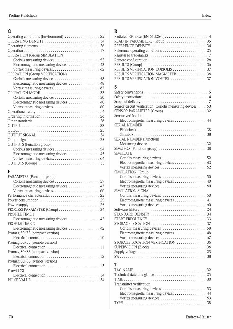
Proline Fieldcheck Index
70 Endress+Hauser
OOperating conditions (Environment) . . . . . . . . . . . . . . . . . 25
OPERATING DENSITY . . . . . . . . . . . . . . . . . . . . . . . . . . . 34
Operating elements . . . . . . . . . . . . . . . . . . . . . . . . . . . . . . 26
Operation . . . . . . . . . . . . . . . . . . . . . . . . . . . . . . . . . . . . . 17
OPERATION (Group SIMULATION)
Coriolis measuring devices . . . . . . . . . . . . . . . . . . . . . . 52
Electromagnetic measuring devices . . . . . . . . . . . . . . . 43
Vortex measuring devices. . . . . . . . . . . . . . . . . . . . . . . 62
OPERATION (Group VERIFICATION)
Coriolis measuring devices . . . . . . . . . . . . . . . . . . . . . . 58
Electromagnetic measuring devices . . . . . . . . . . . . . . . 48
Vortex measuring devices. . . . . . . . . . . . . . . . . . . . . . . 67
OPERATION MODE . . . . . . . . . . . . . . . . . . . . . . . . . . . . . 33
Coriolis measuring devices . . . . . . . . . . . . . . . . . . . . . . 50
Electromagnetic measuring devices . . . . . . . . . . . . . . . 40
Vortex measuring devices. . . . . . . . . . . . . . . . . . . . . . . 60
Operational safety . . . . . . . . . . . . . . . . . . . . . . . . . . . . . . . . 4
Ordering information. . . . . . . . . . . . . . . . . . . . . . . . . . . . . 26
Other standards. . . . . . . . . . . . . . . . . . . . . . . . . . . . . . . . . 26
OUTPUT. . . . . . . . . . . . . . . . . . . . . . . . . . . . . . . . . . . . . . 33
Output . . . . . . . . . . . . . . . . . . . . . . . . . . . . . . . . . . . . . . . 25
OUTPUT SIGNAL . . . . . . . . . . . . . . . . . . . . . . . . . . . . . . . 34
Output signal . . . . . . . . . . . . . . . . . . . . . . . . . . . . . . . . . . 25
OUTPUTS (Function group)
Coriolis measuring devices . . . . . . . . . . . . . . . . . . . . . . 54
Electromagnetic measuring devices . . . . . . . . . . . . . . . 45
Vortex measuring devices. . . . . . . . . . . . . . . . . . . . . . . 64
OUTPUTS (Group) . . . . . . . . . . . . . . . . . . . . . . . . . . . . . . 33
PPARAMETER (Function group)
Coriolis measuring devices . . . . . . . . . . . . . . . . . . . . . . 57
Electromagnetic measuring devices . . . . . . . . . . . . . . . 47
Vortex measuring devices. . . . . . . . . . . . . . . . . . . . . . . 66
Performance characteristics . . . . . . . . . . . . . . . . . . . . . . . . 25
Power consumption. . . . . . . . . . . . . . . . . . . . . . . . . . . . . . 25
Power supply . . . . . . . . . . . . . . . . . . . . . . . . . . . . . . . . . . 25
PROCESS PARAMETER (Group) . . . . . . . . . . . . . . . . . . . . 34
PROFILE TIME 1
Electromagnetic measuring devices . . . . . . . . . . . . . . . 42
PROFILE TIME 2
Electromagnetic measuring devices . . . . . . . . . . . . . . . 42
Promag 50/53 (compact version)
Electrical connection . . . . . . . . . . . . . . . . . . . . . . . . . . 10
Promag 50/53 (remote version)
Electrical connection . . . . . . . . . . . . . . . . . . . . . . . . . . 11
Promag 80/83 (compact version)
Electrical connection . . . . . . . . . . . . . . . . . . . . . . . . . . 12
Promag 80/83 (remote version)
Electrical connection . . . . . . . . . . . . . . . . . . . . . . . . . . 13
Prowirl 72
Electrical connection . . . . . . . . . . . . . . . . . . . . . . . . . . 14
PULSE VALUE . . . . . . . . . . . . . . . . . . . . . . . . . . . . . . . . . 34
RRadiated RF noise (EN 61326-1) . . . . . . . . . . . . . . . . . . . . . 4
READ IN PARAMETERS (Group) . . . . . . . . . . . . . . . . . . . 35
REFERENCE DENSITY . . . . . . . . . . . . . . . . . . . . . . . . . . . 34
Reference operating conditions . . . . . . . . . . . . . . . . . . . . . 25
Registered trademarks. . . . . . . . . . . . . . . . . . . . . . . . . . . . . 7
Remote configuration . . . . . . . . . . . . . . . . . . . . . . . . . . . . 26
RESULTS (Group). . . . . . . . . . . . . . . . . . . . . . . . . . . . . . . 36
RESULTS VERIFICATION CORIOLIS . . . . . . . . . . . . . . . . 37
RESULTS VERIFICATION MAGMETER . . . . . . . . . . . . . . 36
RESULTS VERIFICATION VORTEX . . . . . . . . . . . . . . . . . 37
SSafety conventions . . . . . . . . . . . . . . . . . . . . . . . . . . . . . . . 5
Safety instructions. . . . . . . . . . . . . . . . . . . . . . . . . . . . . . . . 4
Scope of delivery. . . . . . . . . . . . . . . . . . . . . . . . . . . . . . . . . 7
Sensor circuit verification (Coriolis measuring devices) . . . 53
SENSOR PARAMETER (Group) . . . . . . . . . . . . . . . . . . . . 32
Sensor verification
Electromagnetic measuring devices . . . . . . . . . . . . . . . 44
SERIAL NUMBER
Fieldcheck. . . . . . . . . . . . . . . . . . . . . . . . . . . . . . . . . . 38
Simubox . . . . . . . . . . . . . . . . . . . . . . . . . . . . . . . . . . . 38
SERIAL NUMBER (Function)
Measuring device . . . . . . . . . . . . . . . . . . . . . . . . . . . . 32
SIMUBOX (Function group) . . . . . . . . . . . . . . . . . . . . . . . 38
SIMULATE
Coriolis measuring devices . . . . . . . . . . . . . . . . . . . . . 52
Electromagnetic measuring devices . . . . . . . . . . . . . . . 43
Vortex measuring devices . . . . . . . . . . . . . . . . . . . . . . 62
SIMULATION (Group)
Coriolis measuring devices . . . . . . . . . . . . . . . . . . . . . 50
Electromagnetic measuring devices . . . . . . . . . . . . . . . 40
Vortex measuring devices . . . . . . . . . . . . . . . . . . . . . . 60
SIMULATION SIGNAL
Coriolis measuring devices . . . . . . . . . . . . . . . . . . . . . 50
Electromagnetic measuring devices . . . . . . . . . . . . . . . 41
Vortex measuring devices . . . . . . . . . . . . . . . . . . . . . . 60
Software history . . . . . . . . . . . . . . . . . . . . . . . . . . . . . . . . 24
STANDARD DENSITY . . . . . . . . . . . . . . . . . . . . . . . . . . . 34
START FREQUENCY . . . . . . . . . . . . . . . . . . . . . . . . . . . . 33
STORAGE LOCATION . . . . . . . . . . . . . . . . . . . . . . . . . . . 37
Coriolis measuring devices . . . . . . . . . . . . . . . . . . . . . 58
Electromagnetic measuring devices . . . . . . . . . . . . . . . 48
Vortex measuring devices . . . . . . . . . . . . . . . . . . . . . . 67
STORAGE LOCATION VERIFICATION . . . . . . . . . . . . . . 36
SUPERVISION (Block) . . . . . . . . . . . . . . . . . . . . . . . . . . . 36
Supply voltage . . . . . . . . . . . . . . . . . . . . . . . . . . . . . . . . . 25
SW. . . . . . . . . . . . . . . . . . . . . . . . . . . . . . . . . . . . . . . . . . 38
TTAG NAME . . . . . . . . . . . . . . . . . . . . . . . . . . . . . . . . . . . 32
Technical data at a glance . . . . . . . . . . . . . . . . . . . . . . . . . 25
TIME . . . . . . . . . . . . . . . . . . . . . . . . . . . . . . . . . . . . . . . . 30
Transmitter verification
Coriolis measuring devices . . . . . . . . . . . . . . . . . . . . . 53
Electromagnetic measuring devices . . . . . . . . . . . . . . . 44
Vortex measuring devices . . . . . . . . . . . . . . . . . . . . . . 63
TYPE . . . . . . . . . . . . . . . . . . . . . . . . . . . . . . . . . . . . . . . . 38

Proline Fieldcheck Index
Endress+Hauser 71
UUser interface . . . . . . . . . . . . . . . . . . . . . . . . . . . . . . . . . . 26
USER INTERFACE (Block). . . . . . . . . . . . . . . . . . . . . . . . . 29
VVALUE 0_4 mA . . . . . . . . . . . . . . . . . . . . . . . . . . . . . . . . 33
VALUE 20 mA . . . . . . . . . . . . . . . . . . . . . . . . . . . . . . . . . 33
VALUE f- . . . . . . . . . . . . . . . . . . . . . . . . . . . . . . . . . . 33–34
VERIFICATE (Function)
Coriolis measuring devices . . . . . . . . . . . . . . . . . . . . . . 58
Electromagnetic measuring devices . . . . . . . . . . . . . . . 48
Vortex measuring devices . . . . . . . . . . . . . . . . . . . . . . 67
VERIFICATION (Function)
Coriolis measuring devices . . . . . . . . . . . . . . . . . . . . . . 58
Electromagnetic measuring devices . . . . . . . . . . . . . . . 48
Vortex measuring devices . . . . . . . . . . . . . . . . . . . . . . 67
VERIFICATION (Group)
Coriolis measuring devices . . . . . . . . . . . . . . . . . . . . . . 53
Electromagnetic measuring devices . . . . . . . . . . . . . . . 44
Vortex measuring devices . . . . . . . . . . . . . . . . . . . . . . 63
VERSION INFO (Group) . . . . . . . . . . . . . . . . . . . . . . . . . . 38
Vortex measuring devices . . . . . . . . . . . . . . . . . . . . . . . . . 66
WWiring
see Electrical connection
ZZERO POINT . . . . . . . . . . . . . . . . . . . . . . . . . . . . . . . . . . 32

Europe
Austria – Wien
• Endress+Hauser Ges.m.b.H.Tel. (01) 88 05 60, Fax (01) 88 05 63 35
Belarus – Minsk
BelorgsintezTel. (017) 2 50 84 73, Fax (017) 2 50 85 83
Belgium / Luxembourg – Bruxelles
• Endress+Hauser S.A. / N.V.Tel. (02) 2 48 06 00, Fax (02) 2 48 05 53
Bulgaria – Sofia
Intertech-Automation EOODTel. (02) 9 76 96 66, Fax (02) 9 76 96 60
Croatia – Zagreb
• Endress+Hauser GmbH+Co.Tel. (01) 6 63 77 85, Fax (01) 6 63 78 23
Cyprus – Nicosia
I+G Electrical Services Co. Ltd.Tel. (02) 48 47 88, Fax (02) 48 46 90
Czech Republic – Praha 4
• Endress+Hauser Czech s.r.o.Tel. (02) 41 08 04 50, Fax (02) 41 08 04 60
Denmark – Søborg
• Endress+Hauser A/STel. (70) 13 11 32, Fax (70) 13 21 33
Estonia – Tartu
Elvi-Aqua OÜTel. (7) 30 27 32, Fax (7) 30 27 31
Finland – Helsinki
• Metso Endress+Hauser OyTel. (204) 8 31 60, Fax (204) 8 31 61
France – Huningue
• Endress+Hauser S.A.Tel. (389) 69 67 68, Fax (389) 69 48 02
Germany – Weil am Rhein
• Endress+Hauser Messtechnik GmbH+Co. KGTel. (07621) 9 75 01, Fax (07621) 97 55 55
Great Britain – Manchester
• Endress+Hauser Ltd.Tel. (0161) 2 86 50 00, Fax (0161) 9 98 18 41
Greece – Athens
I & G Building ServicesTel. (02) 109 24 15 00, Fax (02) 109 22 17 14
Hungary – Budapest
• Endress+Hauser MagyarországTel. (01) 4 12 04 21, Fax (01) 4 12 04 24
Iceland – Reykjavik
Sindra-Stál hfTel. 5 75 00 00, Fax 5 75 00 10
Ireland – Clane / County Kildare
• Flomeaco Endress+Hauser Ltd.Tel. (045) 86 86 15, Fax (045) 86 81 82
Italy – Cernusco s/N, Milano
• Endress+Hauser S.p.A.Tel. (02) 92 19 21, Fax (02) 92 19 23 62
Latvia – Riga
Elekoms Ltd.Tel. (07) 33 64 44, Fax (07) 33 64 48
Lithuania – Kaunas
UAB Agava Ltd.Tel. (03) 7 20 24 10, Fax (03) 7 20 74 14
Macedonia – Beograd
Meris d.o.o.Tel. (11) 44 42 96 6, Fax (11) 30 85 77 8
Moldavia – Chisinau
S.C. Techno Test SRLTel. (02) 22 61 60, Fax (02) 22 83 13
Netherlands – Naarden
• Endress+Hauser B.V.Tel. (035) 6 95 86 11, Fax (035) 6 95 88 25
Norway – Lierskogen
• Endress+Hauser A/STel. 32 85 98 50, Fax 32 85 98 51
Poland – Wroclaw• Endress+Hauser Polska Sp. z o.o.Tel. (071) 7 80 37 00, Fax (071) 7 80 37 60
Portugal – Cacem• Endress+Hauser Portugal Lda.Tel. (21) 4 26 72 90, Fax (21) 4 26 72 99
Romania – BucharestS.C. Romconseng S.R.L.Tel. (021) 41 12 50 1, Fax (021) 41 01 63 4
Russia – Moscow• OOO Endress+HauserTel. (095) 78 32 85 0, Fax (095) 78 32 85 5
Slovak Republic – BratislavaTranscom Technik s.r.o.Tel. (2) 44 88 86 90, Fax (2) 44 88 71 12
Slovenia – Ljubljana• Endress+Hauser (Slovenija) D.O.O.Tel. (01) 5 19 22 17, Fax (01) 5 19 22 98
Spain – Sant Just Desvern• Endress+Hauser S.A.Tel. (93) 4 80 33 66, Fax (93) 4 73 38 39
Sweden – Sollentuna• Endress+Hauser ABTel. (08) 55 51 16 00, Fax (08) 55 51 16 55
Switzerland – Reinach/BL 1• Endress+Hauser Metso AGTel. (061) 7 15 75 75, Fax (061) 7 11 16 50
Turkey – Levent/IstanbulIntek Endüstriyel Ölcü ve Kontrol SistemleriTel. (0212) 2 75 13 55, Fax (0212) 2 66 27 75
Ukraine – KievPhotonika GmbHTel. (44) 451 85 31, Fax (44) 451 85 31
Yugoslavia Republic – BeogradMeris d.o.o.Tel. (11) 244 29 66, Fax (11) 308 57 78
Africa
Algeria – AnnabaSymes Systemes et MesuresTel. (38) 88 30 03, Fax (38) 88 30 02
Cameroun – DoualaLemelle EnterprisesTel. 988 72 02 , Fax 342 06 73
Egypt – Heliopolis/CairoAnasia Egypt For Trading (S.A.E.)Tel. (02) 2 68 41 59, Fax (02) 2 68 41 69
Ghana – TemaDouglas Electrical Engineering ConsultancyTel. (22) 41 08 47, Fax (27) 752 71 66
Ivory Coast – Abidjan 06CIM-CI S.A.R.L.Tel. 22 48 55 54, Fax 22 48 60 45
Libya – Dahra/TripoliHK International Trading Services CompanyTel. 214 44 17 40, Fax 214 44 46 39
Morocco – CasablancaOussama S.A.Tel. (02) 22 24 13 38, Fax (02) 2 40 26 57
Nigeria – Dopemu, Agege, LagosAutomated Process LimitedTel. (01) 472 99 67, Fax (01) 804 78 03
Senegal – DakarNarmer S.A.R.L.Tel. 823 30 92, Fax 821 17 40
South Africa – Sandton• Endress+Hauser (Pty.) Ltd.Tel. (011) 2 62 80 00, Fax (011) 2 62 80 62
Tunisia – TunisCMR Controle, Maintenance et RegulationTel. (07) 17 93 07 7, Fax (07) 17 88 59 5
America
Argentina – Buenos Aires• Endress+Hauser Argentina S.A.Tel. (11) 45 22 79 70, Fax (11) 45 22 79 09
Brazil – Sao Paulo• Endress+Hauser Controle e Automaçao Ltda.Tel. (011) 50 33 43 33, Fax (011) 50 31 30 67
Canada – Burlington, Ontario• Endress+Hauser Canada Ltd.Tel. (905) 68 19 29 2, Fax (905) 68 19 44 4
Chile – Santiago de Chile• Endress+Hauser (Chile) Ltd.Tel. (02) 3 21 30 09, Fax (02) 3 21 30 25
Colombia – Bogota D.C.Colsein Ltda.Tel. (01) 2 36 76 59, Fax (01) 6 10 78 68
Costa Rica – San JoseEuro-Tec S.A.Tel. 2 20 28 08, Fax 2 96 15 42
Ecuador – QuitoInsetec Cia. Ltda.Tel. (02) 2 26 91 48, Fax (02) 2 46 18 33
El Salvador – San SalvadorAutomatizacion y Control Industrial de El Salvador, S.A. de C.V.Tel. 2 60 24 24, Fax 2 60 56 77
Guatemala – Ciudad de GuatemalaAutomatizacion y Control Industrial, S.A.Tel. (03) 34 59 85, Fax (03) 32 74 31
Honduras – San Pedro Sula, CortesAutomatizacion y Control Industrial de Honduras, S.A. de C.V.Tel. 5 57 91 36, Fax 5 57 91 39
Mexico – Naucalpan de Juárez• Endress+Hauser (México), S.A. de C.V.Tel. (5) 553 71 11 10, Fax (5) 553 71 11 28
Nicaragua – ManaguaAutomatización y Control Industrial de Nicaragua, S.A.Tel. 2 22 61 90, Fax 2 28 70 24
Panama – PaitillaEuro Technology de Panama, S.A.Tel. 290 62 86, Fax 290 62 06
Peru – MirafloresCorsusa InternationalTel. (1) 44 41 20 0, Fax (1) 44 43 66 4
USA – Greenwood, Indiana• Endress+Hauser Inc.Tel. (317) 5 35 71 38, Fax (317) 5 35 84 98
USA – Norcross, Atlanta• Endress+Hauser Systems & Gauging Inc.Tel. (770) 4 47 92 02, Fax (770) 4 47 57 67
Venezuela – CaracasControval C.A.Tel. (212) 9 44 09 66, Fax (212) 9 44 45 54
Asia
Azerbaijan – BakuModcon Systems - BakuTel. (12) 92 98 59, Fax (12) 99 13 72
Brunei – Seria/NegaraAmerican International Industries (B) Sdn. Bhd.Tel. (33) 22 37 37, Fax (33) 22 54 58
Cambodia – Khan Daun Penh, Phnom PenhComin Khmere Co. Ltd.Tel. (23) 42 66 22, Fax (23) 42 60 56
China – Shanghai• Endress+Hauser (Shanghai) Instrumentation Co. Ltd.Tel. (021) 54 90 23 00, Fax (021) 54 90 23 03
China – Beijing• Endress+Hauser (Beijing) Instrumentation Co. Ltd.Tel. (010) 65 88 24 68, Fax (010) 65 88 17 25
Hong Kong – Tsimshatsui / Kowloon• Endress+Hauser (H.K.) Ltd.Tel. 8 52 25 28 31 20, Fax 8 52 28 65 41 71
India – Mumbai• Endress+Hauser (India) Pvt. Ltd.Tel. (022) 56 93 83 33, Fax (022) 56 93 83 30
Indonesia – JakartaPT Grama BazitaTel. (21) 7 95 50 83, Fax (21) 7 97 50 89
Iran – Tehran
Patsa IndustryTel. (021) 8 72 68 69, Fax (021) 8 71 96 66
Israel – Netanya
Instrumetrics Industrial Control Ltd.Tel. (09) 8 35 70 90, Fax (09) 8 35 06 19
Japan – Tokyo
• Sakura Endress Co. Ltd.Tel. (0422) 54 06 11, Fax (0422) 55 02 75
Jordan – Amman
A.P. Parpas Engineering S.A.Tel. (06) 5 53 92 83, Fax (06) 5 53 92 05
Kazakhstan – Almaty
BEI ElectroTel. (72) 30 00 28, Fax (72) 50 71 30
Korea, South – Seoul
• Endress+Hauser (Korea) Co. Ltd.Tel. (02) 26 58 72 00, Fax (02) 26 59 28 38
Kuwait – Safat
United Technical Services Est. For General TradingTel. 2 41 12 63, Fax 2 41 15 93
Lebanon – Jbeil Main Entry
Network EngineeringTel. (3) 94 40 80, Fax (9) 54 80 38
Malaysia – Shah Alam, Selangor Darul Ehsan
• Endress+Hauser (M) Sdn. Bhd.Tel. (03) 78 46 48 48, Fax (03) 78 46 88 00
Pakistan – Karachi
Speedy AutomationTel. (021) 7 72 29 53, Fax (021) 7 73 68 84
Philippines – Manila
Inter Conglomerates Inc.Tel. (2) 637 85 77, Fax (2) 637 51 27
Saudi Arabia – Jeddah
Anasia Trading Co. Ltd.Tel. (02) 6 53 36 61, Fax (02) 6 53 35 04
Singapore – Singapore
• Endress+Hauser (S.E.A.) Pte. Ltd.Tel. (65) 66 82 22, Fax (65) 66 68 48
Sultanate of Oman – Ruwi
Mustafa & Sultan Sience & Industry Co. L.L.C.Tel. 63 60 00, Fax 60 70 66
Taiwan – Taipei
Kingjarl CorporationTel. (02) 27 18 39 38, Fax (02) 27 13 41 90
Thailand – Bangkok 10210
• Endress+Hauser (Thailand) Ltd.Tel. (2) 9 96 78 11-20, Fax (2) 9 96 78 10
United Arab Emirates – Dubai
Descon Trading L.L.C.Tel. (04) 2 65 36 51, Fax (04) 2 65 32 64
Uzbekistan – Tashkent
Im Mexatronika-TesTel. (71) 1 91 77 07, Fax (71) 1 91 76 94
Vietnam – Ho Chi Minh City
Tan Viet BaoTel. (08) 923 52 25, Fax (08) 923 52 27
Australia + New Zealand
Australia – North Ryde NSW 2113
• Endress+Hauser Australia Pty. Ltd.Tel. (02) 88 77 70 00, Fax (02) 88 77 70 99
New Zealand – Auckland
EMC Industrial Group Ltd.Tel. (09) 4 15 51 10, Fax (09) 4 15 51 15
All other countries• Endress+Hauser GmbH+Co. KGInstruments InternationalWeil am Rhein, GermanyTel. (07621) 9 75 02, Fax (07621) 97 53 45
• Members of the Endress+Hauser group
http://www.endress.com
01.04
BA067D/06/en/04.04
50100085
FM+SGML 6.0 ProMoDo