operating instructions -...
TRANSCRIPT

Read this manual carefully before you use this machine and keep it handy for future reference. For safe and correct use, be sure to read the Safety Information in "Setup Guide" before using the machine.
1 About the RC Gate
2 Registering the RC Gate
3 Setting the Auto Discovery
4 Registering Devices with the Communication Server
5 Configuring the Details of the Registered Information
6 Appendix
Operating Instructions


How to Read This Manual
Symbols
The following set of symbols is used in this manual.
Indicates a situation that may result in property damage or malfunction if instructions are not followed. Besure to read the instructions.
Indicates supplementary relevant information.
Indicates where you can find further relevant information.
[ ]
Indicates the names of keys that appear on the computer screen.
Notes
Contents of this manual are subject to change without prior notice.
Certain options might not be available in some countries. For details, contact your local dealer.
Some illustrations in this manual might be slightly different from the machine.
Depending on which country you are in, certain units may be optional. For details, please contact yourlocal dealer.
About the Abbreviation
In these sheets, we use the term RC Gate as an abbreviation of Remote Communication Gate A.
Screens
The explanations in this manual use screen images from Windows XP and Internet Explorer 6.0. If you usedifferent OS, screen images may differ. However, you can perform the same steps.
1

Manuals for This EquipmentThe following manuals describe procedures to operate and maintain this equipment. For safe and efficientoperation of this equipment, all users should read and follow the instructions carefully.
Operating Instructions (this manual)
Provides all of the information on how to use this equipment. Perform the procedures in this manualafter you have completed the procedures in "Setup Guide".
Safety Information/Setup Guide
Provides the information on safe usage of this equipment and how to install/set up it.
• You need not perform the registration procedures explained in this manual if a customer engineer hasalready registered your equipment. However, in order to operate and maintain the equipment, youmust read this manual carefully.
• Adobe Acrobat or Adobe Reader is necessary to view this manual in PDF format.
2

Important• TO THE MAXIMUM EXTENT PERMITTED BY APPLICABLE LAW:
• THE SUPPLIER SHALL NOT BE LIABLE FOR THE RESULT OF OPERATION OF THIS SOFTWAREOR THE USE OF THIS DOCUMENT.
• THE SUPPLIER SHALL NOT BE LIABLE TO YOU FOR DAMAGES OR LOSS OF ANYDOCUMENT OR DATA PRODUCED BY USING THIS SOFTWARE.
• THE SUPPLIER SHALL NOT BE LIABLE TO YOU FOR ANY CONSEQUENTIAL, INCIDENTALOR INDIRECT DAMAGES (INCLUDING, BUT NOT LIMITED TO, DAMAGES FOR LOSS OFPROFITS, BUSINESS INTERRUPTION OR LOSS OF BUSINESS INFORMATION, AND THELIKE) CAUSED BY FAILURE OF THIS SOFTWARE OR LOSS OF DOCUMENTS OR DATA, NORFOR ANY OTHER DAMAGES ARISING OUT OF THE USE OF THIS SOFTWARE, IF THESUPPLIER HAS BEEN ADVISED OF THE POSSIBILITY OF SUCH DAMAGES.
• Some illustrations or explanations in this guide may differ from your product due to improvement orchange in the product.
• The contents of this document are subject to change without notice.
• No part of this document may be duplicated, replicated, reproduced in any form, modified or quotedwithout prior consent of the supplier.
• It is possible that any document or data stored in the computer will be damaged or lost by user errorduring operation or software error. Be sure to back up all important data beforehand. Importantdocuments and data should always be copied or backed up. Documents and data can be lost becauseof malfunction or human error. Furthermore, the customer is responsible for protection measuresagainst computer viruses, worms, and other harmful software.
• Do not remove or insert any disk while operating this software.
3

TrademarksAdobe®, Acrobat®, Acrobat Reader®, and Flash® are either registered trademarks or trademarks ofAdobe Systems Incorporated in the United States and/or other countries.
Microsoft®, Windows®, and Microsoft Internet Explorer® are either registered trademarks or trademarksof Microsoft Corporation in the United States and/or other countries.
Other product names used herein are for identification purposes only and might be trademarks of theirrespective companies. We disclaim any and all rights to those marks.
This product includes software developed by the OpenSSL Project for use in the OpenSSL Toolkit.
(http://www.openssl.org/)
• The product names of Windows XP are as follows:
Microsoft® Windows® XP Professional
Microsoft® Windows® XP Home Edition
4

TABLE OF CONTENTSHow to Read This Manual.................................................................................................................................1
Symbols...........................................................................................................................................................1
Notes...............................................................................................................................................................1
About the Abbreviation..................................................................................................................................1
Screens............................................................................................................................................................1
Manuals for This Equipment...............................................................................................................................2
Important.............................................................................................................................................................3
Trademarks..........................................................................................................................................................4
1. About the RC Gate
What Can be Done with the RC Gate..............................................................................................................9
Outline of the System.......................................................................................................................................10
Guide to Equipment.........................................................................................................................................12
Front..............................................................................................................................................................12
Back..............................................................................................................................................................13
About Options..................................................................................................................................................15
About the RC Gate Monitor............................................................................................................................16
Users of the RC Gate Monitor....................................................................................................................16
To Start the RC Gate Monitor.....................................................................................................................18
Checking the Validity of the Software........................................................................................................19
Proxy Settings (Internet Explorer 6.0)........................................................................................................20
To Close the RC Gate Monitor...................................................................................................................20
2. Registering the RC Gate
Outline of the @Remote Service Registration Wizard...................................................................................21
Operating the @Remote Service Registration Wizard..................................................................................22
3. Setting the Auto Discovery
Outline of the Auto Discovery Setting Wizard...............................................................................................25
Operating the Auto Discovery Setting Wizard..............................................................................................26
When Specifying Auto Discovery Range by IP Address..........................................................................26
When Specifying Auto Discovery Range by Network Segment..............................................................30
4. Registering Devices with the Communication Server
Outline of the Device Registration Wizard....................................................................................................37
Operating the Device Registration Wizard....................................................................................................38
Searching for Devices by IP Address.........................................................................................................38
5

Searching for Devices by Segment............................................................................................................44
Searching for Devices by Host Name........................................................................................................50
5. Configuring the Details of the Registered Information
Name of Screens Displayed from [RC Gate Configuration]........................................................................59
Details of Screens Displayed from [RC Gate Configuration].......................................................................63
Basic..............................................................................................................................................................63
Date/Time....................................................................................................................................................65
Network........................................................................................................................................................66
HTTP Proxy...................................................................................................................................................70
E-mail............................................................................................................................................................72
Access Prohibited IP Address......................................................................................................................75
Ping connection............................................................................................................................................77
Auto Discovery Basic Settings.....................................................................................................................77
Auto Discovery Protocol Settings................................................................................................................78
Edit Auto Discovery Range..........................................................................................................................80
Extended Device Search Setting................................................................................................................83
Registered Device List..................................................................................................................................84
Registered Device Counter..........................................................................................................................89
Common Management...............................................................................................................................90
Shift Device Firmware Update Time...........................................................................................................92
Update Device Firmware............................................................................................................................94
Update Device Firmware Report................................................................................................................95
Service Test Call...........................................................................................................................................96
Device Check Request Call.........................................................................................................................97
Extended Function Setting...........................................................................................................................98
Restart RC Gate............................................................................................................................................99
Shut Down RC Gate..................................................................................................................................100
Service Call................................................................................................................................................101
System Status.............................................................................................................................................103
User Account Settings...............................................................................................................................104
Permissions.................................................................................................................................................106
Authentication for Counter per User Retrieval........................................................................................106
@Remote Service Function Limitation.......................................................................................................108
6

Security Log...............................................................................................................................................110
6. Appendix
LCD Messages...............................................................................................................................................115
Troubleshooting.............................................................................................................................................117
When Error Messages Appear ...............................................................................................................117
If Problems Described in Error Messages Persist ...................................................................................118
When the Office or Devices are Moved ................................................................................................118
To Return the RC Gate .............................................................................................................................118
Error Codes................................................................................................................................................118
Default Settings .........................................................................................................................................119
Specifications for the Main Unit...................................................................................................................121
Information about Installed Software ..........................................................................................................122
INDEX...........................................................................................................................................................123
7

8

1. About the RC GateThis chapter will describe the outline of the RC Gate.
What Can be Done with the RC GateThe following operations are available using the RC Gate:
• Send an automatic service call notifying the Communication Server that a device has malfunctioned.
• Update device firmware.
• Obtain device counter information and send it to the Communication Server.
• Automatically order new supplies, such as toner, when a device indicates that its supplies are low.
• Quickly check the usage status of multiple devices.
9
1

Outline of the SystemThe RC Gate communicates with the Communication Server over the Internet using HTTPS. Mutualauthentication by HTTPS ensures the security of communication between the RC Gate and theCommunication Server.
The Communication Server serves as the HTTPS server, and the RC Gate works as the HTTPS client.
Communication is possible when the following conditions are satisfied:
• Your environment is arranged to be able to access Web sites outside of your network.
• If the proxy server requires authentication, the account and password for the proxy server areavailable.
BSE001S
1. Communication Server
Information sent for various services will be aggregated to this server.
2. Proxy Server and/or Firewalls
You are able to use your proxy server and firewalls with this equipment. When using proxy server, Basicauthentication, Digest authentication, and Windows authentication (only NTLMv2authentication available) canbe used with this equipment.
3. Device
A printer and multifunction machine can be managed by this equipment. This equipment can manage a maximumof 100 devices.
1. About the RC Gate
10
1

If you have installed optional memory and storage to expand the capacity, up to 1,000 devices can be registered.Contact your service representative for details.
For option information, see p.15 "About Options".
4. Computer for Administration
You can manage this equipment by accessing the RC Gate Monitor via Web browser. For details, see p.16"About the RC Gate Monitor".
5. This Equipment (RC Gate)
Intermediates the managed devices and the Communication Server. Sends the device information to theCommunication Server, and receives software to update the devices from the Communication Server.
If you have installed optional memory, the RC Gate can acquire device counter information on a per-user basisfrom specified devices. Contact your service representative for details.
For option information, see p.15 "About Options".
Outline of the System
11
1
Guide to EquipmentThis section explains names and functions of each part.
Front
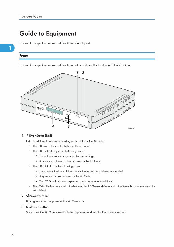
This section explains names and functions of the parts on the front side of the RC Gate.
BSE002S
1. Error Status (Red)
Indicates different patterns depending on the status of the RC Gate:
• The LED is on if the certificate has not been issued.
• The LED blinks slowly in the following cases:
• The entire service is suspended by user settings.
• A communication error has occurred in the RC Gate.
• The LED blinks fast in the following cases:
• The communication with the communication server has been suspended.
• A system error has occurred in the RC Gate.
• The RC Gate has been suspended due to abnormal conditions.
• The LED is off when communication between the RC Gate and Communication Server has been successfullyestablished.
2. Power (Green)
Lights green when the power of the RC Gate is on.
3. Shutdown button
Shuts down the RC Gate when this button is pressed and held for five or more seconds.
1. About the RC Gate
12
1

If the power plug is disconnected before shutting down the RC Gate, the memory/storage will be damaged. Insuch a case, the latest logs, a maximum of an hour, will be lost. Be sure to shut down the RC Gate beforedisconnecting the power plug.
4. Display
Displays the status of the RC Gate on the first line and the IP address of the RC Gate on the second line.
If an error has occurred in the RC Gate, the second line displays an error message. For details about errormessages, see p.115 "LCD Messages".
• If the Error Status LED blinks or an error code is shown on the display, see p.117"Troubleshooting".
• To restart the RC Gate, see p.99 "Restart RC Gate".
Back
This section explains names and functions of the parts on the back side of the RC Gate.
BSE003S
1. PC Port (Maintenance port)
This port is used when a customer engineer performs maintenance, or when the designated administrator connectsa PC to perform initial settings and registration of the RC Gate.
2. LAN Port
The network (Ethernet) interface port to connect the RC Gate to the network. The default IP address is192.168.0.2, but it can be changed.
3. Power Socket
Connect to the power cord.
4. Screw Hole
A hole for a screw to set the power cord anchor bracket
LAN Port Indicator
You can check the connection condition of the PC port (maintenance port) and LAN port.
Guide to Equipment
13
1

BSE004S
1. Orange
Indicates that the RC Gate is connected to the network.
2. Green
Indicates that the RC Gate is transmitting data.
1. About the RC Gate
14
1

About OptionsThis section explains the names and functions of options for the RC Gate.
Expandable memory and storage are available as hardware options for the RC Gate. Contact your servicerepresentative for installation.
• Remote Communication Gate Memory 1000
Expands the memory capacity from 128 MB to 512 MB.
• Remote Communication Gate Storage 1000
Expands the storage capacity from 2 GB to 18 GB.
• The RC Gate can manage a maximum of 100 devices. If you have installed optional memory andstorage to expand the capacity, up to 1,000 devices can be registered. Contact your servicerepresentative for details.
• If you have installed optional memory, the RC Gate can acquire device counter information on a per-user basis from specified devices. Contact your service representative for details.
About Options
15
1

About the RC Gate MonitorThe RC Gate Monitor is the software used to register, monitor, and make settings of the RC Gate. Thesoftware is pre-installed in the RC Gate.
Access the RC Gate Monitor in this equipment from Web browser in the computer. The computer must beon the same network as this equipment.
• Some failure in operation or in displaying might occur in the following cases:
• You use Web browsers lower than the recommended version.
• JavaScript is not set to valid.
• Cookie is not set to valid.
• You set to show cache in the Web browser.
• Page layout may be out of shape depending on the font size settings. We recommend to set it to"Medium" or smaller.
• Some letter deterioration may occur if you use languages that do not correspond to Web browser.
Applicable Operating System
Use operating systems which support the recommended Web browsers below.
Recommended Web Browser
• Microsoft Internet Explorer 6.0 or later
• Adobe Flash Player 9.0 or later must be installed.
Users of the RC Gate Monitor
The following types of users can log in to the RC Gate:
Administrator
The administrator can set up the RC Gate, register devices, change the settings of this equipment, andconfirm the device management information.
When you log in to the RC Gate as the administrator, select the screen to be displayed from "InitialSettings" screen or "RC Gate Configuration" screen.
If you select "Initial Settings" screen, the following menus will appear:
• Setup Wizard
Starts the wizard for referring and registering the RC Gate to the Communication Server.
Once the wizard has been completed, the menu will not be displayed.
1. About the RC Gate
16
1
• @Remote Service Registration Wizard
The menu is displayed when the "Setup Wizard" has been completed.
• Shift Device Firmware Update Time
Starts the wizard for setting the time at which device firmware update by network segment.
The menu is displayed when the "@Remote Service Registration Wizard" has been completed.
• Access Prohibited IP Address
Starts the wizard for specifying the IP address of the network device that you want to prohibitthe RC Gate from accessing.
The menu is displayed when the "@Remote Service Registration Wizard" has been completed.
• Ping Send Permission
Starts the wizard for setting whether to allow ping transmission.
The menu is displayed when the "@Remote Service Registration Wizard" has been completed.
• Auto Discovery Setting Wizard
Starts the wizard for setting the usage and schedule of the Auto Discovery function.
The menu is displayed when the "@Remote Service Registration Wizard" has been completed.
• Device Registration Wizard
Starts the wizard for registering the devices on network with the Communication Server.
The menu is displayed when the "@Remote Service Registration Wizard" has been completed.
General user
A general user can only view the information about the managed devices. General users areresponsible for the managed devices, and cannot change settings of the RC Gate. Up to 10 generalusers can be registered.
General users can view the following screens:
• Registered Device List
Displays the list of devices managed by the RC Gate.
• Details
Displays the details of the devices managed by the RC Gate.
• Call Report Record(s)
Displays the date of a call report, call type, and the device information on which a call has beenreported.
• Registered Device Counter
Displays the counter information of the devices managed by the RC Gate.
• Service Call
Displays the error codes and error information of the RC Gate.
About the RC Gate Monitor
17
1

To view the device information as a general user, a user account must be created by the administrator.For details on account settings, see p.104 "User Account Settings".
• Ask the administrator to remove any general user accounts that are not in use.
To Start the RC Gate Monitor
• Use a browser that can display disguised characters (such as asterisks) during password entry.
• Change the password. Be sure to change the password for actual operation of the RC Gate Monitor.See p.105 "Password" for details.
• For security, further login attempts are rejected if you fail to login three times within five minutes. Waitone minute before attempting to login again.
1. Start the Web browser of the computer, which is on the same network with the RC Gate.
2. Enter "https://{LAN port IP address}:9443/index.html" in "Address".
3. Click [Yes].
4. Select your language from "Language", select [Administrator] or [General user] from "Usertype", and then enter the corresponding password.
When logging in as [General user]:
• Enter the password given by the administrator.
• Enter a user name in "User Name".
5. Select the display screen.
1. About the RC Gate
18
1
6. Click [Login].
• If you cannot access the RC Gate Monitor, see p.20 "Proxy Settings (Internet Explorer 6.0)" andmake the proxy settings.
• Security logs can be configured. See p.110 "Security Log" for details.
Checking the Validity of the Software
Before operating the RC Gate Monitor, check whether the software included in the RC Gate is valid.
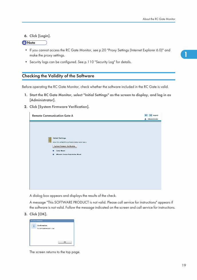
1. Start the RC Gate Monitor, select "Initial Settings" as the screen to display, and log in as[Administrator].
2. Click [System Firmware Verification].
A dialog box appears and displays the results of the check.
A message "This SOFTWARE PRODUCT is not valid. Please call service for instructions" appears ifthe software is not valid. Follow the message indicated on the screen and call service for instructions.
3. Click [OK].
The screen returns to the top page.
About the RC Gate Monitor
19
1
• The screen display will not be limited even if an error exists in the firmware.
• The [System Firmware Verification] button will not be displayed after the RC Gate has been registeredwith the Communication Server.
Proxy Settings (Internet Explorer 6.0)
1. On your Web browser’s [Tools] menu, select [Internet Options...].
2. Click [Connections] tab.
3. Click [LAN Settings...].
4. Under [Proxy Server], select [Use a proxy server for your LAN (These settings will not applyto dial-up or VPN connections).], and click [Advanced...].
5. Under [Exceptions], after [Do not use proxy server for addresses beginning with], enter theIP address of the RC Gate’s LAN port.
6. Click [OK] three times.
To Close the RC Gate Monitor
• An administrator or general user must always click [Logout] before closing the Web browser. If youclose the Web browser without clicking [Logout], the user will remain logged in to RC Gate Monitor.
1. Click [Logout] in the header area.
2. Confirm that the logged in user has logged out the RC Gate Monitor, and then close the Webbrowser.
1. About the RC Gate
20
1

2. Registering the RC GateThis chapter explains the procedure for registering the RC Gate with the Communication Server.
Outline of the @Remote Service RegistrationWizardThis section explains how to register the RC Gate to the Communication Server.
BSE012S
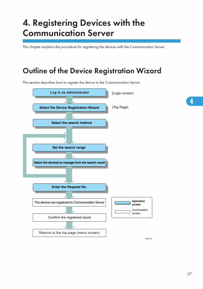
Log in as administrator
Select the @Remote Service Registration Wizard
Make HTTP proxy server setting
Confirm the connection conditions
Returns to the top page (menu screen)
21
2
Operating the @Remote Service RegistrationWizardThe following procedures explain how to register the RC Gate with the Communication Server.
1. Start the Web browser, access the RC Gate Monitor, and log in as [Administrator].
For Details about accessing the RC Gate Monitor, see p.16 "About the RC Gate Monitor".
2. Click [@Remote Service Registration Wizard].
[@Remote Service Registration Wizard] will not appear if it has already been finished. Proceed top.26 "Operating the Auto Discovery Setting Wizard".
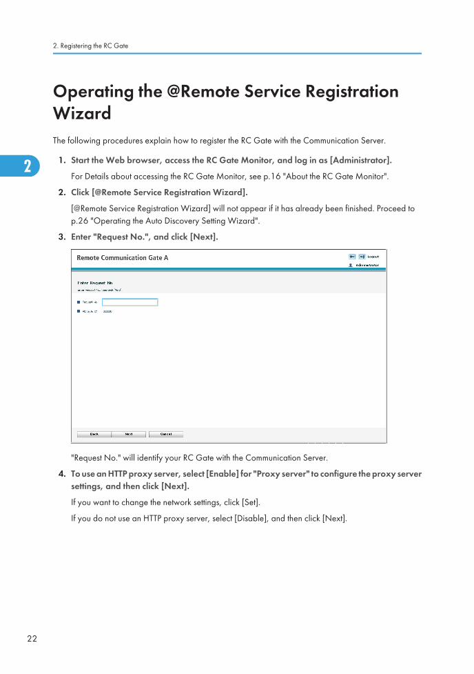
3. Enter "Request No.", and click [Next].
"Request No." will identify your RC Gate with the Communication Server.
4. To use an HTTP proxy server, select [Enable] for "Proxy server" to configure the proxy serversettings, and then click [Next].
If you want to change the network settings, click [Set].
If you do not use an HTTP proxy server, select [Disable], and then click [Next].
2. Registering the RC Gate
22
2

5. Confirm the connection conditions, and click [Next].
It will take a few minutes for the RC Gate to complete confirming the entered settings to theCommunication Server. Wait until the "Confirmation Result" screen appears.
6. Confirm that confirmation is successful, and click [Start Registration].
7. Confirm that registration is successful, and click [OK].
"@Remote Service Registration Wizard" finishes, and the screen returns to the "Initial Settings" screen.
8. Remove the network cable from the PC port.
Restore the network settings of the computer.
Operating the @Remote Service Registration Wizard
23
2
• [OK] will appear when the confirmation or registration fails. Click [OK] and start the wizard againfrom step 3.
2. Registering the RC Gate
24
2

3. Setting the Auto DiscoveryWhen Auto Discovery is enabled, the RC Gate collects information about the devices on the network usingthe specified schedule, and then reports it to the Communication Server.
You can configure the Auto Discovery function using the "Auto Discovery Setting Wizard". The wizardappears when you log in as [Administrator], and "@Remote Service Registration Wizard" has beencompleted.
Outline of the Auto Discovery Setting WizardThis section explains the outline of enabling the Auto Discovery function.
Log in as administrator
Returns to the top page (menu screen)BSE014S
25
3
Operating the Auto Discovery Setting WizardThis section explains how to specify the method by which the RC Gate discovers devices using AutoDiscovery.
There are two methods by which Auto Discovery can discover devices on a network:
• By searching through a specified range of IP addresses.
• By searching through specified network segments.
• You can import search ranges from a CSV file stored on your computer. For details on creating a CSVfile, see p.35 "To Create a CSV File".
When Specifying Auto Discovery Range by IP Address
This section explains how to specify the Auto Discovery search range by specifying IP address of the device.
1. Start the RC Gate Monitor if it is not started, and then log in as [Administrator].
2. Click [Auto Discovery Setting Wizard].
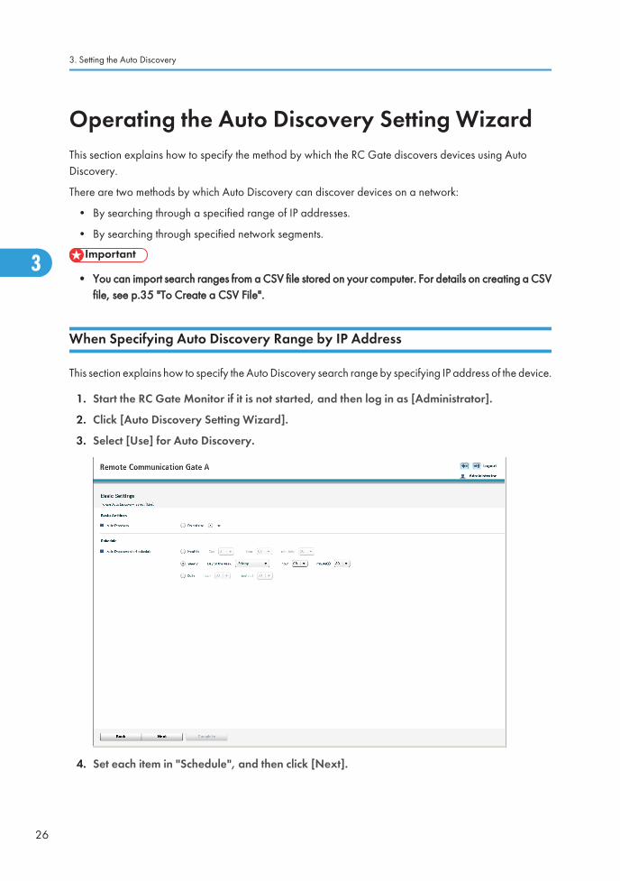
3. Select [Use] for Auto Discovery.
4. Set each item in "Schedule", and then click [Next].
3. Setting the Auto Discovery
26
3

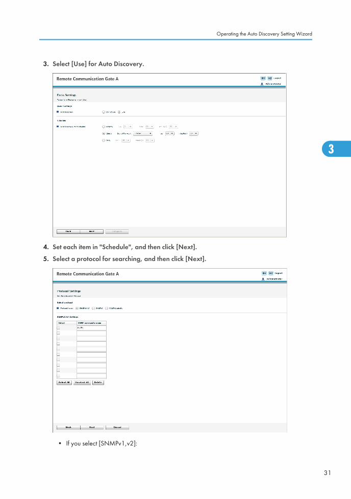
5. Select a protocol for searching, and then click [Next].
• If you select [SNMPv1,v2]:
SNMP community name serves as a "password" when the RC Gate tries to access the SNMPcorrespondent devices. See the operating instructions for each device for details.
Enter the SNMP community name in order of highest frequency to lowest frequency. (You canenter up to 30 ASCII characters per name. You can enter up to 10 names). Remove any SNMPcommunity names that are not in use on your network.
Leave the item blank if the managing devices are only HTTP correspondent devices.
• If you select [SNMPv3]:
Enter at least one set for user name, authentication password, and encryption password. Youcan enter up to 10 sets.
• If you select [SNMPv3 priority]:
This protocol uses the SNMPv3 and SNMPv1,v2 protocols. The RC Gate will first attempt tosearch a device using the SNMPv3 protocol. If a device does not support SNMPv3, the RCGate will attempt to search a device using the SNMPv1,v2 protocol.
To select all items in the list, click [Select All].
To deselect all selected items in the list, click [Unselect All].
6. Select [IP address range] for the search method.
Operating the Auto Discovery Setting Wizard
27
3

7. Set the search ranges.
• When entering the ranges directly:
Enter the starting IP address and finishing IP address in "x.x.x.x" format ("x" stands for any numberfrom 0 to 255). You can enter up to 256 sets of addresses.
Enter a higher IP address for the finishing IP address than for the starting IP address.
If you set "0.0.0.0" for the finishing address, the range of IP address on that line will not besearched.
An error will occur if the value for the starting IP address is "0.0.0.0" and the value for the finishingIP address is other than "0.0.0.0".
• When importing from a CSV file:
Click [Browse], locate your CSV file, and then click [Import].
Once the search ranges have been imported from the CSV file, all previously specified rangeswill be deleted.
• When obtaining IP address information from the router:
Select [Auto retrieve from the router]. Specify the number of search hops (0 to 10), and thenclick [Start Retrieval].
You can switch pages by clicking the button on the left/right of the displayed number. The number ofdisplayed ranges on the current page can be changed using the "Display items" list.
3. Setting the Auto Discovery
28
3

8. Click [Go to Access Prohibited IP Address Settings], and then specify the IP address that youwant to prohibit the RC Gate from accessing.
If you do not need to prohibit any IP addresses, proceed to step 10.
• When entering the IP address directly:
Enter the IP address in "x.x.x.x" format ("x" stands for any number from 0 to 255). You can enterup to 256 addresses.
• When importing from a CSV file:
Click [Browse], locate your CSV file, and then click [Import CSV].
Once the search ranges have been imported from the CSV file, all previously specified rangeswill be deleted.
9. Select the check boxes of the IP address you want to prohibit, and then click [OK].
10. Click [Start Search].
Device searching starts.
11. Edit the range.
To delete the range, select the check box of the range that you want to delete, and click [Delete].
12. From the list of discovered devices, specify whether to make the devices be target of AutoDiscovery in "Discovery".
Enter a name for the search ranges in "Range Name" as necessary. The maximum length for the nameis 61 ASCII characters.
Operating the Auto Discovery Setting Wizard
29
3

13. Click [Complete].
When Specifying Auto Discovery Range by Network Segment
This section explains how to specify the Auto Discovery search range by specifying the network segments.
1. Start the RC Gate Monitor if it is not started, and then log in as [Administrator].
2. Click [Auto Discovery Setting Wizard].
3. Setting the Auto Discovery
30
3
3. Select [Use] for Auto Discovery.
4. Set each item in "Schedule", and then click [Next].
5. Select a protocol for searching, and then click [Next].
• If you select [SNMPv1,v2]:
Operating the Auto Discovery Setting Wizard
31
3

SNMP community name serves as a "password" when the RC Gate tries to access the SNMPcorrespondent devices. See the operating instructions for each device for details.
Enter the SNMP community name in order of highest frequency to lowest frequency. (You canenter up to 30 ASCII characters per name. You can enter up to 10 names). Remove any SNMPcommunity names that are not in use on your network.
Leave the item blank if the managing devices are only HTTP correspondent devices.
• If you select [SNMPv3]:
Enter at least one set for user name, authentication password, and encryption password. Youcan enter up to 10 sets.
• If you select [SNMPv3 priority]:
This protocol uses the SNMPv3 and SNMPv1,v2 protocols. The RC Gate will first attempt tosearch a device using the SNMPv3 protocol. If a device does not support SNMPv3, the RCGate will attempt to search a device using the SNMPv1,v2 protocol.
To select all items in the list, click [Select All].
To deselect all selected items in the list, click [Unselect All].
6. Select [Segment range] for the search method.
Select one of the following search methods:
• Segment search by Sweep
The RC Gate sends a ping to each IP address (host addresses 1 to 254) in a specified networksegment.
• Segment search by Broadcast
The RC Gate issues an SNMP broadcast and searches any responding addresses within thespecified network segment.
3. Setting the Auto Discovery
32
3
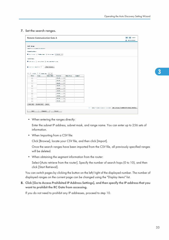
7. Set the search ranges.
• When entering the ranges directly:
Enter the subnet IP address, subnet mask, and range name. You can enter up to 256 sets ofinformation.
• When Importing from a CSV file:
Click [Browse], locate your CSV file, and then click [Import].
Once the search ranges have been imported from the CSV file, all previously specified rangeswill be deleted.
• When obtaining the segment information from the router:
Select [Auto retrieve from the router]. Specify the number of search hops (0 to 10), and thenclick [Start Retrieval].
You can switch pages by clicking the button on the left/right of the displayed number. The number ofdisplayed ranges on the current page can be changed using the "Display items" list.
8. Click [Go to Access Prohibited IP Address Settings], and then specify the IP address that youwant to prohibit the RC Gate from accessing.
If you do not need to prohibit any IP addresses, proceed to step 10.
Operating the Auto Discovery Setting Wizard
33
3

• When entering the IP address directly:
Enter the IP address in "x.x.x.x" format ("x" stands for any number from 0 to 255). You can enterup to 256 addresses.
• When importing from a CSV file:
Click [Browse], locate your CSV file, and then click [Import CSV].
Once the search ranges have been imported from the CSV file, all previously specified rangeswill be deleted.
9. Select the check boxes of the IP address you want to prohibit, and then click [OK].
10. Click [Start Search].
Device searching starts.
11. Edit the range.
To delete the range, select the check box of the range that you want to delete, and click [Delete].
12. From the list of discovered devices, specify whether to make the devices be target of AutoDiscovery in "Discovery".
Enter a name for the search ranges in "Range Name" as necessary. The maximum length for the nameis 61 ASCII characters.
3. Setting the Auto Discovery
34
3

13. Click [Complete].
To Create a CSV File
To import a CSV file, you must create a CSV file.
CSV file for specifying the search ranges by IP address:
To create the CSV file, enter the information for each IP address range by separating it with a comma.Each line should contain the following items: starting IP address, finishing IP address, discovery, rangename, and comment. You can enter up to 256 sets of addresses.
Example:
BSE015S
192.168.0.1,192.168.0.2,Enable,abc,1-63192.168.0.3,192.168.0.4,Disable,def,64-127192.168.0.5,192.168.0.6,Enable,ghi,128-191192.168.0.7,192.168.0.8,Enable,jkl,192-254
Operating the Auto Discovery Setting Wizard
35
3

CSV file for specifying the search ranges by network segment:
To create the CSV file, enter the information for each network segment by separating it with a comma.Each line should contain the following items: subnet IP address, subnet mask, discovery, range name,and comment. You can enter up to 256 sets of information.
Example:
BSE016S
192.168.1.0,255.255.255.0,Enable,abc,1-63192.168.2.0,255.255.255.0,Disable,def,64-127192.168.3.0,255.255.255.0,Enable,ghi,128-191192.168.4.0,255.255.255.0,Enable,jkl,192-254
CSV file for specifying access prohibited IP addresses:
To create the CSV file, enter the information for each IP address by separating it with a comma. Eachline should contain the IP address and comment. You can enter up to 256 sets of addresses.
Example:
BSE018S
3. Setting the Auto Discovery
36
3
4. Registering Devices with theCommunication ServerThis chapter explains the procedure for registering the devices with the Communication Server.
Outline of the Device Registration WizardThis section describes how to register the device to the Communication Server.
Returns to the top page (menu screen)
Log in as administrator
BSE013S
37
4

Operating the Device Registration WizardThis section explains how to register devices on network with the Communication Server.
There are three methods by which the RC Gate can discover devices on a network:
• By searching through a specified range of IP addresses.
• By searching through specified network segments.
• By searching through specified host names.
• The search results can contain up to 100 devices. If you have installed optional memory and storage,the results can contain up to 1,000 devices. Contact your service representative for details.
• You can import search ranges from a CSV file stored on your computer. For details on creating a CSVfile, see p.56 "To Create a CSV File".
Searching for Devices by IP Address
This section explains how to search for devices you want to register with the Communication Server byspecifying IP address ranges.
1. Start the RC Gate Monitor if it is not started, and then log in as [Administrator].
2. Click [Device Registration Wizard].
4. Registering Devices with the Communication Server
38
4

3. Select a protocol for searching, and then click [Next].
• If you select [SNMPv1,v2]:
SNMP community name serves as a "password" when the RC Gate tries to access the SNMPcorrespondent devices. See the operating instructions for each device for details.
Enter the SNMP community name in order of highest frequency to lowest frequency. (You canenter up to 30 ASCII characters per name. You can enter up to 10 names). Remove any SNMPcommunity names that are not in use on your network.
Leave the item blank if the managing devices are only HTTP correspondent devices.
• If you select [SNMPv3]:
Enter at least one set for user name, authentication password, and encryption password. Youcan enter up to 10 sets.
• If you select [SNMPv3 priority]:
This protocol uses the SNMPv3 and SNMPv1,v2 protocols. The RC Gate will first attempt tosearch a device using the SNMPv3 protocol. If a device does not support SNMPv3, the RCGate will attempt to search a device using the SNMPv1,v2 protocol.
To select all items in the list, click [Select All].
To deselect all selected items in the list, click [Unselect All].
Operating the Device Registration Wizard
39
4

4. Select [IP address range] for the search method.
4. Registering Devices with the Communication Server
40
4

5. Set the search ranges.
• When entering the ranges directly:
Enter the starting IP address and finishing IP address in "x.x.x.x" format ("x" stands for any numberfrom 0 to 255). You can enter up to 256 sets of addresses.
Enter a higher IP address for the finishing IP address than for the starting IP address.
If you set "0.0.0.0" for the finishing address, the range of IP address on the line will not besearched.
An error will occur if the value for the starting IP address is "0.0.0.0" and the value for the finishingIP address is other than "0.0.0.0".
• When importing from a CSV file:
Click [Browse], locate your CSV file, and then click [Import CSV].
Once the search ranges have been imported from the CSV file, all previously specified rangeswill be deleted.
6. Click [Go to Access Prohibited IP Address Settings], and then specify the IP address that youwant to prohibit the RC Gate from accessing.
If you do not need to prohibit any IP addresses, proceed to step 8.
Operating the Device Registration Wizard
41
4

• When entering the IP address directly:
Enter the IP address in "x.x.x.x" format ("x" stands for any number from 0 to 255). You can enterup to 256 addresses.
• When importing from a CSV file:
Click [Browse], locate your CSV file, and then click [Import CSV].
Once the search ranges have been imported from the CSV file, all previously specified rangeswill be deleted.
7. Select the check boxes of the IP address you want to prohibit, and then click [OK].
The screen returns to "Search Range Settings".
8. Click [Start Search].
Device searching starts.
4. Registering Devices with the Communication Server
42
4
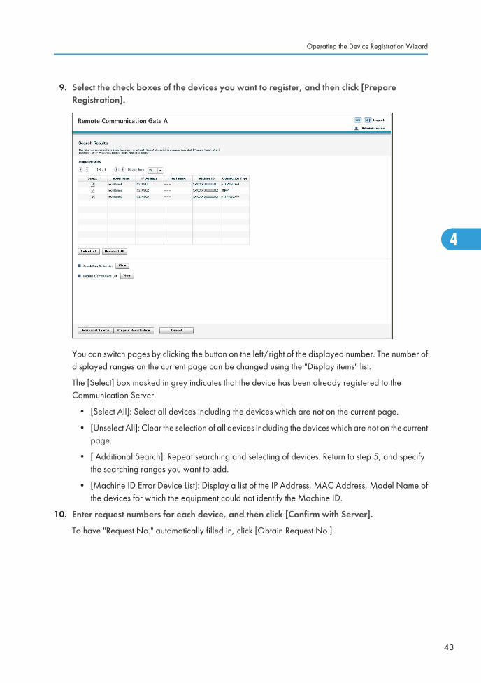
9. Select the check boxes of the devices you want to register, and then click [PrepareRegistration].
You can switch pages by clicking the button on the left/right of the displayed number. The number ofdisplayed ranges on the current page can be changed using the "Display items" list.
The [Select] box masked in grey indicates that the device has been already registered to theCommunication Server.
• [Select All]: Select all devices including the devices which are not on the current page.
• [Unselect All]: Clear the selection of all devices including the devices which are not on the currentpage.
• [ Additional Search]: Repeat searching and selecting of devices. Return to step 5, and specifythe searching ranges you want to add.
• [Machine ID Error Device List]: Display a list of the IP Address, MAC Address, Model Name ofthe devices for which the equipment could not identify the Machine ID.
10. Enter request numbers for each device, and then click [Confirm with Server].
To have "Request No." automatically filled in, click [Obtain Request No.].
Operating the Device Registration Wizard
43
4

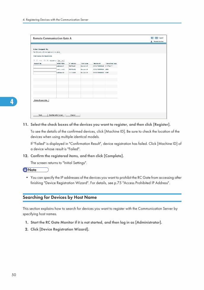
11. Select the check boxes of the devices you want to register, and then click [Register].
To see the details of the confirmed devices, click [Machine ID]. Be sure to check the location of thedevices when using multiple identical models.
If "Failed" is displayed in "Confirmation Result", device registration has failed. Click [Machine ID] ofa device whose result is "Failed".
12. Confirm the registered items, and then click [Complete].
The screen returns to "Initial Settings".
• You can specify the IP addresses of the devices you want to prohibit the RC Gate from accessing afterfinishing "Device Registration Wizard". For details, see p.75 "Access Prohibited IP Address".
Searching for Devices by Segment
This section explains how to search for devices you want to register with the Communication Server byspecifying network segments.
1. Start the RC Gate Monitor if it is not started, and then log in as [Administrator].
2. Click [Device Registration Wizard].
4. Registering Devices with the Communication Server
44
4

3. Select a protocol for searching, and then click [Next].
• If you select [SNMPv1,v2]:
SNMP community name serves as a "password" when the RC Gate tries to access the SNMPcorrespondent devices. See the operating instructions for each device for details.
Enter the SNMP community name in order of highest frequency to lowest frequency. (You canenter up to 30 ASCII characters per name. You can enter up to 10 names). Remove any SNMPcommunity names that are not in use on your network.
Leave the item blank if the managing devices are only HTTP correspondent devices.
• If you select [SNMPv3]:
Enter at least one set for user name, authentication password, and encryption password. Youcan enter up to 10 sets.
• If you select [SNMPv3 priority]:
This protocol uses the SNMPv3 and SNMPv1,v2 protocols. The RC Gate will first attempt tosearch a device using the SNMPv3 protocol. If a device does not support SNMPv3, the RCGate will attempt to search a device using the SNMPv1,v2 protocol.
To select all items in the list, click [Select All].
To deselect all selected items in the list, click [Unselect All].
Operating the Device Registration Wizard
45
4

4. Select [Segment range] for the search method.
Select one of the following search methods:
• Segment search by Sweep
The RC Gate sends a ping to each IP address (host addresses 1 to 254) in a specified networksegment.
• Segment search by Broadcast
The RC Gate issues an SNMP broadcast and searches any responding addresses within thespecified network segment.
To select all items in the list, click [Select All].
To deselect all selected items in the list, click [Unselect All].
4. Registering Devices with the Communication Server
46
4

5. Set the search ranges.
• When entering the ranges directly:
Enter the searching ranges and subnet mask as segment information. You can enter up to 256sets of information.
• When importing from a CSV file:
Click [Browse], locate your CSV file, and then click [Import CSV].
Once the search ranges have been imported from the CSV file, all previously specified rangeswill be deleted.
6. Click [Go to Access Prohibited IP Address Settings], and then specify the IP address that youwant to prohibit the RC Gate from accessing.
If you do not need to prohibit any IP addresses, proceed to step 8.
Operating the Device Registration Wizard
47
4

• When entering the IP address directly:
Enter the IP address in "x.x.x.x" format ("x" stands for any number from 0 to 255). You can enterup to 256 addresses.
• When importing from a CSV file:
Click [Browse], locate your CSV file, and then click [Import CSV].
Once the search ranges have been imported from the CSV file, all previously specified rangeswill be deleted.
7. Select the check boxes of the IP address you want to prohibit, and then click [OK].
The screen returns to "Search Range Settings".
8. Click [Start Search].
Device searching starts.
4. Registering Devices with the Communication Server
48
4

9. Select the check boxes of the devices you want to register, and then click [PrepareRegistration].
You can switch pages by clicking the button on the left/right of the displayed number. The number ofdisplayed ranges on the current page can be changed using the "Display items" list.
The [Select] box masked in grey indicates that the device has been already registered to theCommunication Server.
• [Select All]: Select all devices including the devices which are not on the current page.
• [Unselect All]: Clear the selection of all devices including the devices which are not on the currentpage.
• [Additional Search]: Repeat searching and selecting of devices. Return to step 5, and specifythe searching ranges you want to add.
• [Machine ID Error Device List]: Display a list of the IP Address, MAC Address, Model Name ofthe devices for which the equipment could not identify the Machine ID.
10. Enter request numbers for each device, and then click [Confirm with Server].
To have "Request No." automatically filled in, click [Obtain Request No.].
Operating the Device Registration Wizard
49
4
11. Select the check boxes of the devices you want to register, and then click [Register].
To see the details of the confirmed devices, click [Machine ID]. Be sure to check the location of thedevices when using multiple identical models.
If "Failed" is displayed in "Confirmation Result", device registration has failed. Click [Machine ID] ofa device whose result is "Failed".
12. Confirm the registered items, and then click [Complete].
The screen returns to "Initial Settings".
• You can specify the IP addresses of the devices you want to prohibit the RC Gate from accessing afterfinishing "Device Registration Wizard". For details, see p.75 "Access Prohibited IP Address".
Searching for Devices by Host Name
This section explains how to search for devices you want to register with the Communication Server byspecifying host names.
1. Start the RC Gate Monitor if it is not started, and then log in as [Administrator].
2. Click [Device Registration Wizard].
4. Registering Devices with the Communication Server
50
4

3. Select a protocol for searching, and then click [Next].
• If you select [SNMPv1,v2]:
SNMP community name serves as a "password" when the RC Gate tries to access the SNMPcorrespondent devices. See the operating instructions for each device for details.
Enter the SNMP community name in order of highest frequency to lowest frequency. (You canenter up to 30 ASCII characters per name. You can enter up to 10 names). Remove any SNMPcommunity names that are not in use on your network.
Leave the item blank if the managing devices are only HTTP correspondent devices.
• If you select [SNMPv3]:
Enter at least one set for user name, authentication password, and encryption password. Youcan enter up to 10 sets.
• If you select [SNMPv3 priority]:
This protocol uses the SNMPv3 and SNMPv1,v2 protocols. The RC Gate will first attempt tosearch a device using the SNMPv3 protocol. If a device does not support SNMPv3, the RCGate will attempt to search a device using the SNMPv1,v2 protocol.
To select all items in the list, click [Select All].
To deselect all selected items in the list, click [Unselect All].
Operating the Device Registration Wizard
51
4

4. Select [Host name] for the search method.
4. Registering Devices with the Communication Server
52
4

5. Set the search ranges.
• When entering the ranges directly:
Enter host names. You can enter up to 256 names.
• When importing from a CSV file:
Click [Browse], locate your CSV file, and then click [Import CSV].
Once the search ranges have been imported from the CSV file, all previously specified rangeswill be deleted.
6. Click [Go to Access Prohibited IP Address Settings], and then specify the IP address that youwant to prohibit the RC Gate from accessing.
If you do not need to prohibit any IP addresses, proceed to step 8.
Operating the Device Registration Wizard
53
4

• When entering the IP address directly:
Enter the IP address in "x.x.x.x" format ("x" stands for any number from 0 to 255). You can enterup to 256 addresses.
• When importing from a CSV file:
Click [Browse], locate your CSV file, and then click [Import CSV].
Once the search ranges have been imported from the CSV file, all previously specified rangeswill be deleted.
7. Select the check boxes of the IP address you want to prohibit, and then click [OK].
The screen returns to "Search Range Settings".
8. Click [Start Search].
Device searching starts.
4. Registering Devices with the Communication Server
54
4
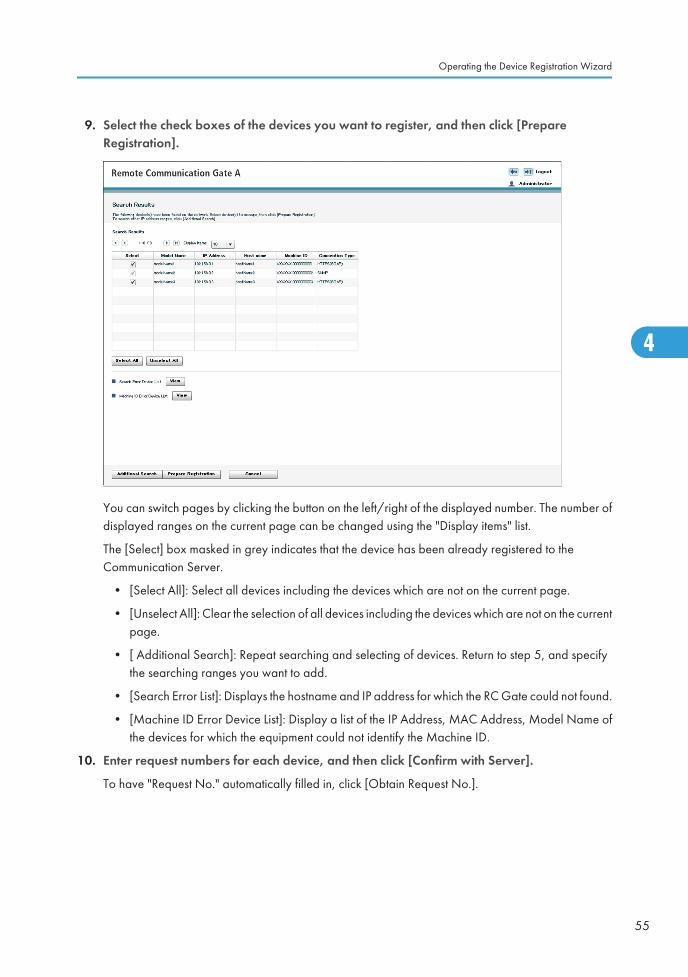
9. Select the check boxes of the devices you want to register, and then click [PrepareRegistration].
You can switch pages by clicking the button on the left/right of the displayed number. The number ofdisplayed ranges on the current page can be changed using the "Display items" list.
The [Select] box masked in grey indicates that the device has been already registered to theCommunication Server.
• [Select All]: Select all devices including the devices which are not on the current page.
• [Unselect All]: Clear the selection of all devices including the devices which are not on the currentpage.
• [ Additional Search]: Repeat searching and selecting of devices. Return to step 5, and specifythe searching ranges you want to add.
• [Search Error List]: Displays the hostname and IP address for which the RC Gate could not found.
• [Machine ID Error Device List]: Display a list of the IP Address, MAC Address, Model Name ofthe devices for which the equipment could not identify the Machine ID.
10. Enter request numbers for each device, and then click [Confirm with Server].
To have "Request No." automatically filled in, click [Obtain Request No.].
Operating the Device Registration Wizard
55
4

11. Select the check boxes of the devices you want to register, and then click [Register].
To see the details of the confirmed devices, click [Machine ID]. Be sure to check the location of thedevices when using multiple identical models.
If "Failed" is displayed in "Confirmation Result", device registration has failed. Click [Machine ID] ofa device whose result is "Failed".
12. Confirm the registered items, and then click [Complete].
The screen returns to "Initial Settings"
• You can specify the IP addresses of the devices you want to prohibit the RC Gate from accessing afterfinishing "Device Registration Wizard". For details, see p.75 "Access Prohibited IP Address".
To Create a CSV File
To import a CSV file, you must create a CSV file.
CSV file for specifying the search ranges by IP address:
For each IP address range, enter the starting IP address and finishing IP address, separated by acomma. Enter each address range on a separate line. You can enter up to 256 sets of addresses.
4. Registering Devices with the Communication Server
56
4
Example:
BSE019S
192.168.0.1,192.168.0.2192.168.0.3,192.168.0.4192.168.0.5,192.168.0.6192.168.0.7,192.168.0.8
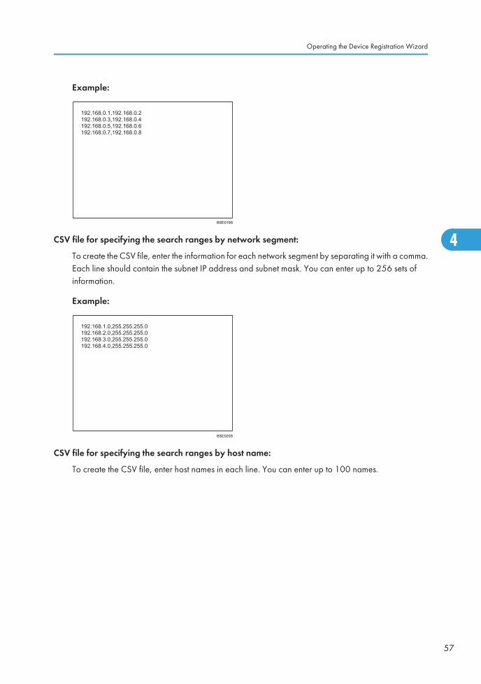
CSV file for specifying the search ranges by network segment:
To create the CSV file, enter the information for each network segment by separating it with a comma.Each line should contain the subnet IP address and subnet mask. You can enter up to 256 sets ofinformation.
Example:
BSE020S
192.168.1.0,255.255.255.0192.168.2.0,255.255.255.0192.168.3.0,255.255.255.0192.168.4.0,255.255.255.0
CSV file for specifying the search ranges by host name:
To create the CSV file, enter host names in each line. You can enter up to 100 names.
Operating the Device Registration Wizard
57
4

Example:
BSE017S
CSV file for specifying access prohibited IP addresses:
To create the CSV file, enter the information for each IP address by separating it with a comma. Eachline should contain the IP address and comment. You can enter up to 256 sets of addresses.
Example
BSE018S
4. Registering Devices with the Communication Server
58
4

5. Configuring the Details of theRegistered InformationThis chapter explains operations that can be done from each screen of the "RC Gate Configuration".
Name of Screens Displayed from [RC GateConfiguration]The following tables provide the menus that are displayed when [RC Gate Configuration] has been selectedat login.
Menus and the screens differ whether the logged in user is [Administrator] or [General user].
Administrator
59
5
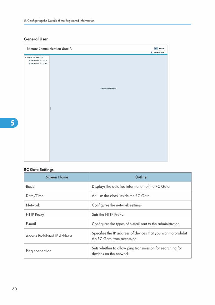
General User
RC Gate Settings
Screen Name Outline
Basic Displays the detailed information of the RC Gate.
Date/Time Adjusts the clock inside the RC Gate.
Network Configures the network settings.
HTTP Proxy Sets the HTTP Proxy.
E-mail Configures the types of e-mail sent to the administrator.
Access Prohibited IP AddressSpecifies the IP address of devices that you want to prohibitthe RC Gate from accessing.
Ping connectionSets whether to allow ping transmission for searching fordevices on the network.
5. Configuring the Details of the Registered Information
60
5

Auto Discovery
Screen Names Outline
Basic SettingsSets basic item for Auto Discovery, such as usage andschedule.
Protocol Settings Sets the search protocol for Auto Discovery.
Edit Auto Discovery RangeSets the ranges of IP address or network segments for AutoDiscovery.
Device Management
Screen Names Outline
Extended Device Search Setting Sets whether to enable the extended device searching.
Registered Device ListDisplays the information of the devices managed by the RCGate.
Registered Device Counter Displays device counter list screen.
Common ManagementDisplays settings common to all devices managed by the RCGate.
Shift Device Firmware Update Time Specifies the time of device firmware update for each segment.
Update Device FirmwareWhen a notice comes from the Communication Server,updates the firmware of the devices managed by the RCGate.
Update Device Firmware Report Displays the previous device firmware update history.
Maintenance
Screen Names Outline
Service Test Call Tests communications with the Communication Server.
Device Check Req. CallTests communications with the Communication Server andsends the results to the Communication Server.
Restart RC Gate Reboots the RC Gate.
Shut Down RC Gate Shuts down the RC Gate.
Service Call Displays the substances of the errors.
System Status Displays the system status of the RC Gate.
Name of Screens Displayed from [RC Gate Configuration]
61
5
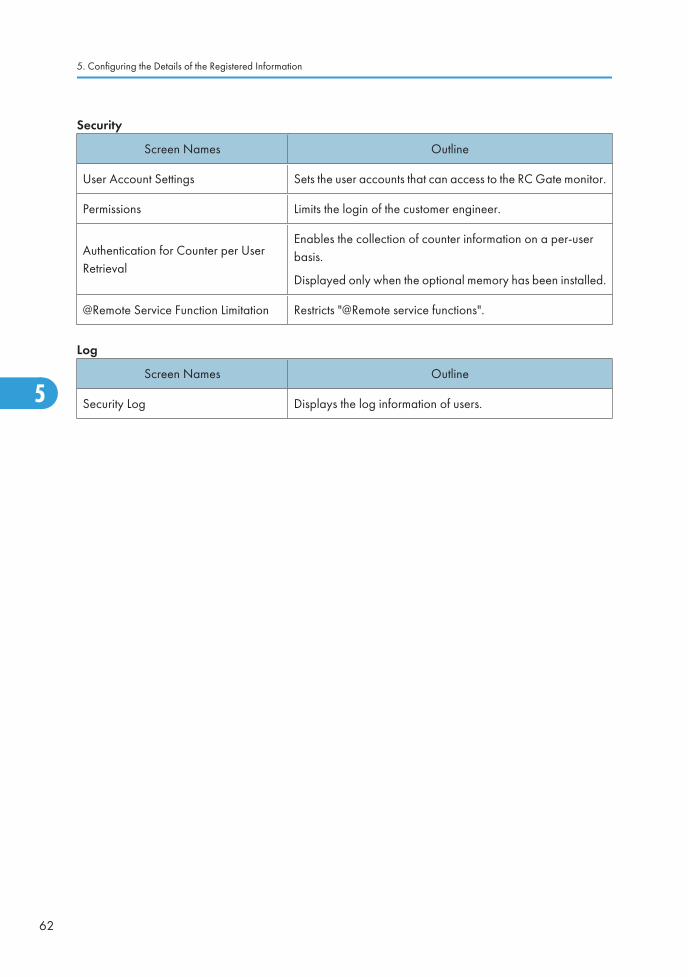
Security
Screen Names Outline
User Account Settings Sets the user accounts that can access to the RC Gate monitor.
Permissions Limits the login of the customer engineer.
Authentication for Counter per UserRetrieval
Enables the collection of counter information on a per-userbasis.
Displayed only when the optional memory has been installed.
@Remote Service Function Limitation Restricts "@Remote service functions".
Log
Screen Names Outline
Security Log Displays the log information of users.
5. Configuring the Details of the Registered Information
62
5

Details of Screens Displayed from [RC GateConfiguration]This section explains the items displayed on each screen.
Buttons Displayed on Each Screen
Button Names Outline
ApplyApplies the current settings. The clock starts when you click thisbutton on the "Date/Time" screen.
OK Displays a confirmation dialog.
BackReturns to the previous screen without applying the currentsettings.
Basic
You can confirm the detailed information of the RC Gate. To display the screen, click [RC Gate Settings] -[Basic].
Details of Screens Displayed from [RC Gate Configuration]
63
5

Item Descriptions
RC Gate IDA serial number to identify the RC Gate. A unique ID is set tothe RC Gate.
Model name A model name for the RC Gate.
RC Gate location A place/section where the RC Gate is set.
Application version Software version that is built into the RC Gate.
Application last updated The last update date of the built-in software.
Platform versionThe version of the base software that operates the built-inapplications.
Platform last updated The last update date of the platform.
Firmware common components version The version of the common software used by the RC Gate.
5. Configuring the Details of the Registered Information
64
5

Item Descriptions
Firmware common components lastupdated
The last update date of the common software.
OS version The current operating system version of the RC Gate.
OS last updatedThe last update date of the operating system that is built intothe RC Gate.
Service depot The service depot of the RC Gate.
Service depot contact The phone number of the service depot.
Number of devices to manageThe number of devices that can be managed by the RCGate.
Counter per User Counter information on a per-user basis.
Storage capacity (standard) The storage capacity, not including expanded storage.
Storage capacity (extended)The storage capacity of the expanded storage. Does notinclude the standard storage capacity.
Memory capacity (standard) The memory capacity, not including expanded memory.
Memory capacity (extended)The memory capacity of the expanded memory. Does notinclude the standard memory capacity.
Log max. capacity The maximum value of the log files which the RC Gate collects.
Log collection levelThe log level for which the RC Gate collects (Errors, warnings,operation, and information).
Permit sending IP addressesThe current condition if sending the IP addresses of the RCGate and the registered devices to the Communication Serveris permitted or not.
System Firmware ValidityClick [Verify Firmware] to check the validity of the softwareincluded in the RC Gate.
Date/Time
You can confirm and change the clock of the RC Gate. To display the settings screen, click [RC GateSettings] - [Date/Time].
Details of Screens Displayed from [RC Gate Configuration]
65
5

• Check the time and date regularly, and correct them if necessary.
Item Descriptions
Time zoneThe standard time of the place where the RC Gate is set (Thetime zone indicates the time difference from UniversalCoordinated Time).
Set date Set the current date of the place where the RC Gate is set.
Set timeSet the current time of the place where the RC Gate is set. Setit to the current time.
Network
You can change and confirm the network settings of the RC Gate. To display the settings screen, click [RCGate Settings] - [Network].
After changing the network settings, you have to log in to the RC Gate again. Click the URL that appearson the screen to re-open the Web browser. If you are using a DHCP server, directly enter the URL thatappears on the screen in the address bar of your browser.
5. Configuring the Details of the Registered Information
66
5

LAN Port
Item Descriptions
DHCP Select [Enable] for the environment using the DHCP server.
IP addressAn IP address for the RC Gate (LAN port). If [Enable] is selectedfor the DHCP, an IP address that is assigned by the DHCPserver will be displayed.
MAC address A MAC address of the RC Gate (LAN port).
Subnet maskA subnet mask for the RC Gate. If [Enable] is selected for theDHCP, a subnet mask that is assigned by the DHCP server willbe displayed.
Default gateway addressA gateway address for the RC Gate. If [Enable] is selected forthe DHCP, an IP address that is assigned by the DHCP serverwill be displayed.
Ethernet speed Select the Ethernet speed for the LAN port of the RC Gate.
DNS Server
Item Descriptions
Main DNS server
Enter the IP address of the DNS server which the RC Gatemainly uses. Enter the IP address in "x.x.x.x" format ("x" standsfor a number from 0 to 255).
This is not required when you enter the proxy server or SMTPserver by its IP address instead of its name.
Sub DNS server
Enter the IP address of the Sub DNS server to use a secondaryDNS Server when the main DNS server cannot be used forsome reason. Enter the IP address in "x.x.x.x" format ("x" standsfor a number from 0 to 255).
IEEE802.1x authentication
Item Descriptions
IEEE802.1x authenticationTo change IEEE802.1x authentication settings, click [Set] todisplay the setting screen.
Details of Screens Displayed from [RC Gate Configuration]
67
5
Maintenance Port
Item Descriptions
IP addressAn IP address for the PC port (maintenance port). If you cannotuse 192.168.10.1 for the PC port in your environment, contactyour service representative.
MAC address A MAC address for the PC port.
Subnet mask A subnet mask for the PC port.
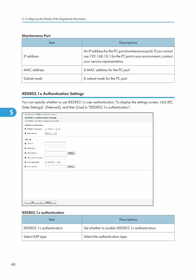
IEEE802.1x Authentication Settings
You can specify whether to use IEEE802.1x user authentication. To display the settings screen, click [RCGate Settings] - [Network], and then [Use] in "IEEE802.1x authentication".
IEEE802.1x authentication
Item Descriptions
IEEE802.1x authentication Set whether to enable IEEE802.1x authentication.
Select EAP type Select the authentication type.
5. Configuring the Details of the Registered Information
68
5

EAP-TLS
Item Descriptions
User name The login user name for the authentication server.
Domain name The login domain name for the authentication server.
Client certificateEnter the certificate password or click [Browse] to select thecertificate.
Client certificate passwordEnter the password required on server authentication. This isdisplayed only when the authentication is enabled.
Server authenticationSet whether to enable the server authentication that uses routecertificate. This is displayed only when the authentication isenabled.
Server certificateEnter the certificate password or click [Browse] to select thecertificate. This is displayed only when the authentication isenabled.
PEAP
Item Descriptions
User name The login user name for the authentication server.
Domain name The login domain name for the authentication server.
Tunneling user nameSet the user name for the tunneling authentication. This isdisplayed only when the authentication is enabled.
Tunneling passwordTo use IEEE802.1x authentication, enter the certificatepassword. This is displayed only when the authentication isenabled.
Server authenticationSet whether to enable the server authentication that uses routecertificate. This is displayed only when the authentication isenabled.
Server certificateEnter the certificate password or click [Browse] to select thecertificate. This is displayed only when the authentication isenabled.
Details of Screens Displayed from [RC Gate Configuration]
69
5

EAP-TTLS
Item Descriptions
User name The login user name for the authentication server.
Domain name The login domain name for the authentication server.
Tunneling method Set the tunneling method.
Tunneling user nameSet the user name for the tunneling authentication. This isdisplayed only when the authentication is enabled.
Tunneling passwordTo use IEEE802.1x authentication, enter the certificatepassword. This is displayed only when the authentication isenabled.
Server authenticationSet whether to enable the server authentication that uses routecertificate. This is displayed only when the authentication isenabled.
Server certificateEnter the certificate password or click [Browse] to select thecertificate. This is displayed only when the authentication isenabled.
HTTP Proxy
You can specify whether to use the HTTP proxy for communication between the RC Gate andCommunication Server. To display the settings screen, click [RC Gate Settings] - [HTTP Proxy].
5. Configuring the Details of the Registered Information
70
5
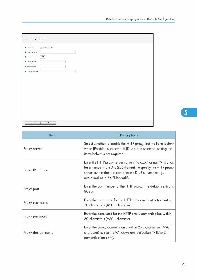
Item Descriptions
Proxy serverSelect whether to enable the HTTP proxy. Set the items belowwhen [Enable] is selected. If [Disable] is selected, setting theitems below is not required.
Proxy IP address
Enter the HTTP proxy server name in "x.x.x.x" format ("x" standsfor a number from 0 to 255) format. To specify the HTTP proxyserver by the domain name, make DNS server settingsexplained on p.66 "Network".
Proxy portEnter the port number of the HTTP proxy. The default setting is8080.
Proxy user nameEnter the user name for the HTTP proxy authentication within30 characters (ASCII character).
Proxy passwordEnter the password for the HTTP proxy authentication within30 characters (ASCII character).
Proxy domain nameEnter the proxy domain name within 255 characters (ASCIIcharacter) to use the Windows authentication (NTLMv2authentication only).
Details of Screens Displayed from [RC Gate Configuration]
71
5

You can change and confirm the e-mail settings for the RC Gate. To display the settings screen, click [RCGate Settings] - [E-mail].
• E-mail for the administrator is sent in plain text.
RC Gate E-mail address
Item Descriptions
RC Gate E-mail address (for sender)
An e-mail address for the RC Gate that is used to send thefollowing types of e-mail:
• Communication suspend/recovery notice
• Device suspend notice
• Device firmware update notice
Default: rc_gate
Enter the e-mail address within 126 characters (ASCIIcharacter).
5. Configuring the Details of the Registered Information
72
5
Item Descriptions
RC Gate E-mail address (for receiver)
An e-mail address to send a reply e-mail to the RC Gate. Youcan set a different e-mail address from the RC Gate e-mailaddress (for sender). You can set multiple addresses bydividing each e-mail address with a comma. Enter theaddresses within 255 characters (ASCII character).
Send Test E-mail (button)
Send a test e-mail to check the settings. The RC Gate will senda test e-mail to [RC Gate admin's E-mail address] when youclick this button.
This button will not be displayed until the RC Gate setting iscompleted.
RC Gate admin's E-mail address
An e-mail address of the administrator that receives e-mailmessages such as "communication suspend notice" and"communication recovery notice".
This item will not be displayed until the RC Gate setting iscompleted.
Number of times to resend E-mailSet the number of retries to the SMTP server when an e-mailtransmission fails. Set the item from 1 to 10.
Resend E-mail interval timeSet the period of retries to the SMTP server when an e-mailtransmission fails. Set the item from 1 to 60 seconds.
SMTP Server
Item Descriptions
SMTP server address
Specify the IP address for the SMTP server to send the followinge-mails to the administrator:
• Communication suspend/recovery
• Device suspend
• Device firmware update
To specify using the IP address: Enter the address in "x.x.x.x"format ("x" stands for a number from 0 to 255) format.
To specify using the domain name: Make DNS server settingsexplained on p.66 "Network".
SMTP server portA port number for the SMTP server.
Generally, set the item to 25.
Details of Screens Displayed from [RC Gate Configuration]
73
5

Item Descriptions
SMTP_AUTH
Select [Enable] if your SMTP Server uses the SMTPauthentication. Select [Disable] if your SMTP does not use theSMTP authentication or uses the POP before SMTPauthentication.
SMTP_AUTH authentication methodSet the item when "SMTP_AUTH" is set to [Enable]. Select theitem from [Auto], [DIGEST-MD5], [CRAM-MD5], [LOGIN]and [PLAIN].
User name
The user name (user ID) used for the SMTP_AUTHauthentication. Generally, the same e-mail address as [RCGate E-mail address (for sender)] is applied, but it may differfor security reasons.
Password
A password for [User name] used for the SMTP_AUTHauthentication. Generally, the same password as [RC Gate E-mail address (for sender)] is applied, but it may differ forsecurity reasons.
POP Server
Item Descriptions
POP before SMTPSelect [Enable] if your SMTP uses the POP before SMTPauthentication. Select [Disable] if your server does not use theSMTP authentication or uses the SMTP_AUTH authentication.
POP server addressThe IP address or the name of the POP server for using the "POPbefore SMTP" authentication.
POP server portThe number of the POP server port for using the "POP beforeSMTP" authentication. Generally, set the item to 110.
User nameThe user name (user ID) used for the POP before SMTPauthentication.
Password The password used for the POP before SMTP authentication.
Wait time after authenticationSet the wait time longer if an error occurs with the POP beforeSMTP authentication. Set the time between 0 to 30 seconds.
• For details about the types of e-mails that are sent to the administrator, see "Setup Guide".
5. Configuring the Details of the Registered Information
74
5

Checking the Settings with the Test E-mail
Follow the following procedure to check that an e-mail can be sent without an error.
Before setting the items, contact the system administrator for the authentication method of the SMTP server.
1. Click [Send Test E-mail].
2. Check if the administrator has received the test e-mail.
If the test e-mail has been received, operate with the current settings.
If the test e-mail has not been received, enter the e-mail address for the administrator in "RC Gate E-mail address (for sender)", and repeat steps 1 and 2.
Ask your service representative if the e-mail has not been received even after correction of the settings.
• Make sure to enter the characters that follow "@" of the e-mail address.
• When an error occurs with the POP before the SMTP authentication, set the [Wait time afterauthentication] longer.
Access Prohibited IP Address
You can prohibit certain IP addresses from being accessed by the RC Gate. To display the settings screen,click [RC Gate Settings] - [Access Prohibited IP Address].
• When using the DHCP server, the prohibited IP addresses might be assigned to the managing devices.In this case, the RC Gate cannot collect the device information.
Details of Screens Displayed from [RC Gate Configuration]
75
5

IP address
Item Descriptions
CSV fileClick [Browse] to locate the CSV file for specifying accessprohibited IP addresses.
Browse (button) Specify a CSV file location for importing.
Import CSV (button) Start importing the specified CSV file.
Access Prohibited IP Address
Item Descriptions
IP AddressSpecify the IP address that you want to prohibit the RC Gatefrom accessing.
CommentYou can enter a comment for each IP address, using up to 61characters (ASCII character).
Select All (button) Select all the items in the list.
Unselect All (button) Deselect all the selected items in the list.
5. Configuring the Details of the Registered Information
76
5

Item Descriptions
Delete (button) Delete all the selected items in the list.
Ping connection
You can select whether to allow ping transmissions for device searching. To display the settings screen,click [RC Gate Settings] - [Ping connection].
tem Descriptions
Ping connectionSelect [Do not permit] to prohibit ping transmission. When [Donot permit] is selected, SNMP will be used instead of Ping.
Auto Discovery Basic Settings
This section explains basic settings for Auto Discovery. To display the settings screen, click [Auto Discovery]- [Basic Settings].
Details of Screens Displayed from [RC Gate Configuration]
77
5

Item Descriptions
Auto DiscoverySet whether to use Auto Discovery. The default setting is [Donot use].
ScheduleSet the period of time to run Auto Discovery. The default settingis [Monthly].
Auto Discovery Protocol Settings
You can make protocol information settings used for Auto Discovery. To display the settings screen, click[Auto Discovery] - [Protocol Settings].
5. Configuring the Details of the Registered Information
78
5

Item Descriptions
SNMP protocolSet the SNMP protocol to be enabled. The default setting is[SNMPv1,v2].
SNMP community name
Set the community name used for searching the devices. SNMPcommunity name works as a password when the RC Gate triesto access the SNMP correspondent devices. The default settingis "public".
You can enter a maximum of 30 characters (ASCII character)for each community name.
User name
The user name used for the SNMP authentication method. Theitem has not been set at the factory.
Enter the name with ASCII characters.
Authentication password
Enter the password for the "User name" used for the SNMPauthentication method. The item has not been set at the factory.
Enter the password with ASCII characters.
Authentication protocol Set the protocol used for the SNMP authentication method.
Details of Screens Displayed from [RC Gate Configuration]
79
5

Item Descriptions
Encryption password
Enter the encrypted password used for the SNMPauthentication method. The item has not been set at the factory.
Enter the password with ASCII characters.
Encryption protocolSet the encrypted protocol used for the SNMP authenticationmethod.
Context NameSet the name used for accessing the device information inSNMPv3 authentication. Set the name within 32 characters(ASCII character).
Edit Auto Discovery Range
Set the range of devices on the network to use Auto Discovery. To display the settings screen, click [AutoDiscovery] - [Edit Auto Discovery Range].
Item Descriptions
Search methodSelect [IP address range] or [Segment range] to specify themethod for searching method. If you have specified to[Segment range], select [Sweep] or [Broadcast].
Entry methodSelect [Import CSV file] or [Auto retrieve from the router] tospecify the entry method.
CSV file Specify a CSV file used for setting the IP addresses.
Search hop number (0-10)Enter the router layer to be searched (to what extent the searchshould be performed) when [Auto retrieve from the router] hasbeen selected.
Go to Access Prohibited IP AddressSettings (button)
Displays "Access Prohibited IP Address Settings" screen. Youcan set the IP addresses to prohibit the RC Gate from accessing.For details, see p.75 "Access Prohibited IP Address".
5. Configuring the Details of the Registered Information
80
5

When Segment range is Selected
Item Descriptions
RangeThe network address to use Auto Discovery. Enter the IPaddress in "x.x.x.x" format ("x" stands for a number from 0 to255).
Subnet MaskThe subnet mask to determine the enable range for the"Range". Enter the subnet mask in "x.x.x.x" format ("x" standsfor a number from 0 to 255).
Discovery Select to set Auto Discovery enable for the device or not.
Range NameThe network address name entered for the IP address in[Range].
Comment Enter comments for each [Range] within 61 characters.
Select All (button) Select the all the ranges in the list.
Unselect All (button) Deselect the all selected items in the list.
Delete (button) Delete the ranges whose check boxes are selected.
Details of Screens Displayed from [RC Gate Configuration]
81
5

When IP address range is Selected
Item Descriptions
Start IP AddressBeginning of the IP address range. Enter the IP address in"x.x.x.x" format ("x" stands for a number from 0 to 255).
End IP AddressEnd of the IP address range. Enter the IP address in "x.x.x.x"format ("x" stands for a number from 0 to 255).
DiscoverySelect whether or not to use the IP address range for AutoDiscovery.
Range NameYou can enter a name for each range, using up to 61characters.
CommentYou can enter a comment for each range, using up to 61characters.
Select All (button) Select all the ranges in the list.
5. Configuring the Details of the Registered Information
82
5
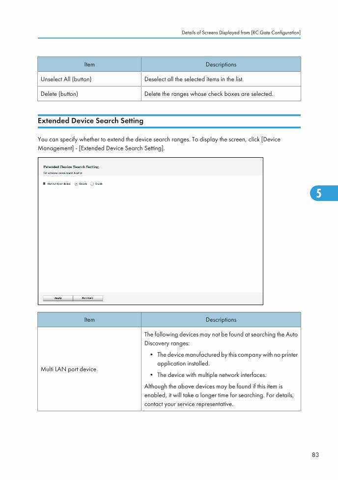
Item Descriptions
Unselect All (button) Deselect all the selected items in the list.
Delete (button) Delete the ranges whose check boxes are selected.
Extended Device Search Setting
You can specify whether to extend the device search ranges. To display the screen, click [DeviceManagement] - [Extended Device Search Setting].
Item Descriptions
Multi LAN port device
The following devices may not be found at searching the AutoDiscovery ranges:
• The device manufactured by this company with no printerapplication installed.
• The device with multiple network interfaces.
Although the above devices may be found if this item isenabled, it will take a longer time for searching. For details,contact your service representative.
Details of Screens Displayed from [RC Gate Configuration]
83
5
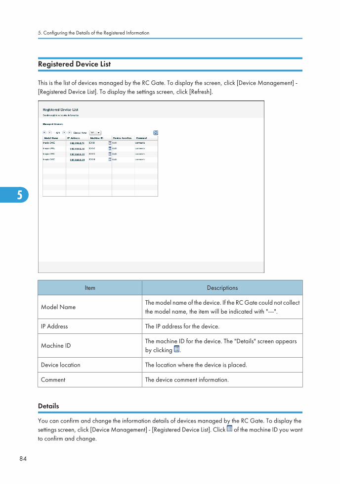
Registered Device List
This is the list of devices managed by the RC Gate. To display the screen, click [Device Management] -[Registered Device List]. To display the settings screen, click [Refresh].
Item Descriptions
Model NameThe model name of the device. If the RC Gate could not collectthe model name, the item will be indicated with "---".
IP Address The IP address for the device.
Machine IDThe machine ID for the device. The "Details" screen appearsby clicking .
Device location The location where the device is placed.
Comment The device comment information.
Details
You can confirm and change the information details of devices managed by the RC Gate. To display thesettings screen, click [Device Management] - [Registered Device List]. Click of the machine ID you wantto confirm and change.
5. Configuring the Details of the Registered Information
84
5
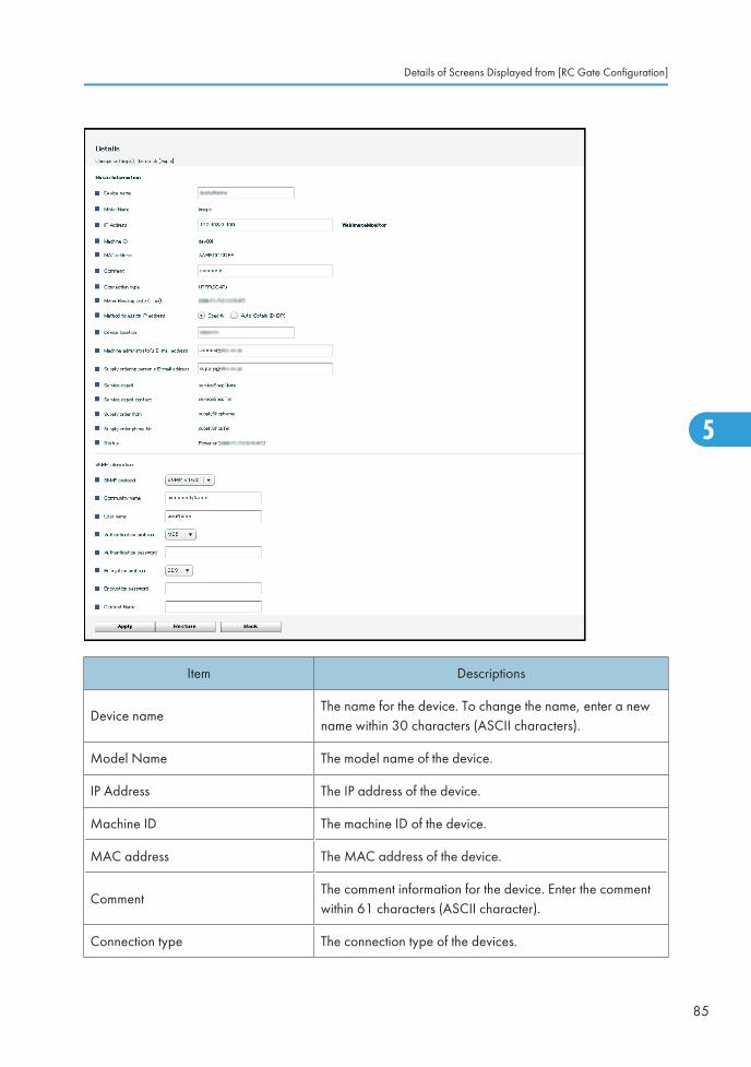
Item Descriptions
Device nameThe name for the device. To change the name, enter a newname within 30 characters (ASCII characters).
Model Name The model name of the device.
IP Address The IP address of the device.
Machine ID The machine ID of the device.
MAC address The MAC address of the device.
CommentThe comment information for the device. Enter the commentwithin 61 characters (ASCII character).
Connection type The connection type of the devices.
Details of Screens Displayed from [RC Gate Configuration]
85
5

Item Descriptions
Meter Reading Date (Time)The date and time when the RC Gate reads the counter of thedevice.
Method to assign IP addressThe method to assign IP address for the devices on the network.Select from [Specify] and [Auto-Obtain (DHCP)].
Device locationThe name of the place where the device is located. To changethe name, enter a new name within 30 characters (ASCIIcharacter).
Machine administrator's E-mail address
The e-mail address for the device administrator. Notice e-mailssuch as "updating device firmware" and "device suspension"are sent to this address. Enter the address within 120characters (ASCII character).
Supply ordering person's E-mailaddress
The e-mail address for the personnel responsible for keepingsupplies. Enter the address within 120 characters (ASCIIcharacter). Depending on the area and service availability,the address might not be displayed.
Service depot Your service representative.
Service depot contact The phone number of your service representative.
Supply order fromYour supply representative. Depending on the area andservice availability, the address might not be displayed.
Supply order phone No.The phone number of your supply representative. Dependingon the area and service availability, the address might not bedisplayed.
Status Displays the operation status of the device.
SNMP Information
Item Descriptions
SNMP protocol Set the SNMP protocol version that is currently valid.
Community nameThe community name for the device which is obtained by theSNMP protocol. To change the name, enter a new name within30 characters (ASCII character). The default setting is "Public".
5. Configuring the Details of the Registered Information
86
5

Item Descriptions
User nameThe login user name for the SNMP authentication server. Tochange the name, enter a new name within 32 characters(ASCII character).
Authentication protocolSet the protocol to be used for the SNMP authenticationmethod.
Authentication passwordEnter the password for "User name" to be used for the SNMPauthentication within 32 characters (ASCII character).
Encryption protocolSet the encryption protocol to be used for the SNMPauthentication method.
Encryption passwordEnter the encryption password to be used for the SNMPauthentication within 32 characters (ASCII character).
Context NameSet the name used for accessing the device information inSNMPv3 authentication. Set the name within 32 characters(ASCII character).
Call Report Record(s)
Displays the date of call report, call type, and the device information on which a call has been reported.A maximum of 100 reports can be stored. To display the screen, click [Device Management] - [RegisteredDevice List] - [Device Call Notification Record].
Details of Screens Displayed from [RC Gate Configuration]
87
5

Item Descriptions
Report Time and Date
The time and date when a call from the device was reportedto the Communication Server:
• Calls reported within the last hour and calls with"Reporting..." in "Report Result" are shown in red.
• Calls reported within the last 24 hours are shown inyellow.
Call Type
There are following types of call type:
• Service call
• Manual call
• Supply call
5. Configuring the Details of the Registered Information
88
5

Item Descriptions
Report Result
Results of the report from the Communication Server:
• Succeeded
• Failed
• Outside of service time
• Reporting failed
• Reporting
Model NameThe model name of the device on which a call has beenreported.
IP Address The IP address of the device on which a call has been reported.
Machine ID The device ID on which a call has been reported.
RemarksDetailed information such as the service call number andsupply call.
Registered Device Counter
This is the list of the managed devices. You can confirm the counter information of the managed devices.To display the settings screen, click [Device Management] - [Registered Device Counter].
Details of Screens Displayed from [RC Gate Configuration]
89
5

Item Descriptions
Machine ID The machine ID for the device.
Model NameThe model name of the device. If the RC Gate could not collectthe model name, it will be indicated with "---".
IP Address The IP address for the device.
Total Counter for Full Color Displays the total counter of full color.
Total Counter for B&W Displays the total counter of monochrome.
Total Counter Displays the total counter of the managed device.
Connection Type Displays the connection type of the managed device.
Collection Time and DateDisplays the latest date and time when the counter informationwas collected.
Common Management
You can confirm the settings to manage the registered devices. To display the screen, click [DeviceManagement] - [Common Management].
5. Configuring the Details of the Registered Information
90
5

Device Information Collection Management
Item Descriptions
Interval time to retrieve deviceinformation
The period of time to receive the information from devices.
Interval time to re-retrieve deviceinformation
The period of time to retry when the RC Gate could not receiveinformation from devices.
Number of times to re-retrieve deviceinformation
The number of times to retry when the RC Gate could notreceive information from devices.
Counter Information Collection Management
Item Descriptions
Interval time to retrieve device counterinformation
The period of time to receive counter data from devices.
Interval time to re-retrieve devicecounter information
The period of time to retry when the RC Gate could not receivecounter information from devices.
Details of Screens Displayed from [RC Gate Configuration]
91
5

Item Descriptions
Number of times to re-retrieve devicecounter information
The number of times to retry when the RC Gate could notreceive counter information from devices.
Network Connection Management
Item Descriptions
Interval time to refresh deviceconnection (HTTP)
The period of time to check the connection to devicescommunicated with HTTP protocol.
Interval time to refresh deviceconnection (SNMP)
The period of time to check the connection to devicescommunicated with SNMP protocol.
Interval time to detect device warning(SNMP)
The period of time to detect the warnings from devicescommunicated with SNMP protocol.
Interval time to start repeat searchfunction for devices (HTTP and SNMP)
The period of time to start searching again for lost devicesconnected to the network.
Interval time to start repeat searchdevices (HTTP and SNMP)
The period of time to start searching again for lost devicesconnected to the network.
Time lapse before devices areconsidered temporarily suspended(HTTP and SNMP)
The period of time to decide on lost devices connected to thenetwork being temporarily suspended.
Time lapse before devices areconsidered suspended (HTTP andSNMP)
The period of time to decide on lost devices connected to thenetwork being suspended.
Devices to repeat search (HTTP andSNMP)
Select the target device on the network on which to repeatsearching from [Only auto-obtained (DHCP) IP address(es)]and[ Auto-obtained (DHCP) and specified IP address(es)].
Repeat search methodDisplays the method for repeat searching when the device ona network has been lost.
Shift Device Firmware Update Time
Considering time zone or work starting time difference, you can set time at which device firmware updateis performed by network segment. To display the settings screen, click [Device Management] – [Shift DeviceFirmware Update Time]. A maximum of 255 segments can be set.
5. Configuring the Details of the Registered Information
92
5
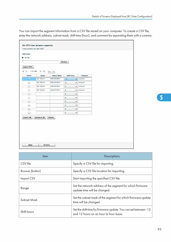
You can import the segment information from a CSV file stored on your computer. To create a CSV file,enter the network address, subnet mask, shift time (hour), and comment by separating them with a comma.
Item Descriptions
CSV file Specify a CSV file for importing.
Browse (button) Specify a CSV file location for importing.
Import CSV Start importing the specified CSV file.
RangeSet the network address of the segment for which firmwareupdate time will be changed.
Subnet MaskSet the subnet mask of the segment for which firmware updatetime will be changed.
Shift hoursSet the shift time for firmware update. You can set between -12and 12 hours on an hour to hour basis.
Details of Screens Displayed from [RC Gate Configuration]
93
5

Item Descriptions
CommentSet the device comment information. You can enter a maximumof 61 characters (ASCII character).
Select All (button) Select the all the items in the list.
Unselect All (button) Deselect all the selected items in the list.
Delete (button) Delete the segment specified by "Select" box.
Update Device Firmware
You can update the device firmware and display the update schedule. To display the settings screen, click[Device Management] - [Update Device Firmware].
When the administrator receives "<<<Remote Communication Gate A>>> [[[ Notice: Update DeviceFirmware ]]]" e-mail and clicks a URL link, the RC Gate monitor starts up, and this screen appearsimmediately after login.
5. Configuring the Details of the Registered Information
94
5

Item Descriptions
Update (button)
Execute firmware update.
The button will not appear when there is no update schedule,the schedule update is running, or before the update isscheduled.
List of Device(s) to Update (button)
Display the following items:
• ID of the device for which update is possible
• Update state such as preparing to update/preparingcompleted
• Update time (when update has been completed)
• Update results
The button will not appear if there is no updating schedule.
Update allowable from The date and time when the device will be able to update.
Prohibited Time for UpdateThe period of time when the firmware update will beprohibited.
Update allowable period
The period of time when the firmware can be updated, startingfrom the first day when the firmware is able to update. If theupdate is not executed in this period, it will be considered thatthe update has failed.
URL to download firmware(s) The location where the firmware is downloaded from.
Message The message from the Communication Server.
Update Device Firmware Report
You can confirm the result of previous device firmware update. To display the screen, click [DeviceManagement] - [Update Device Firmware Report].
Details of Screens Displayed from [RC Gate Configuration]
95
5
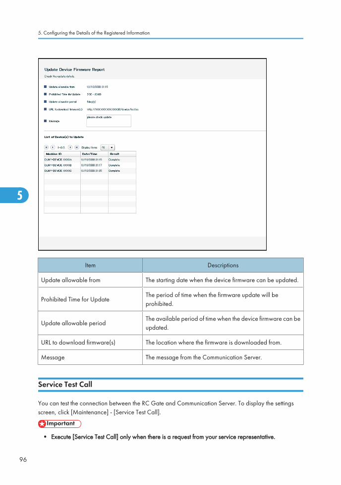
Item Descriptions
Update allowable from The starting date when the device firmware can be updated.
Prohibited Time for UpdateThe period of time when the firmware update will beprohibited.
Update allowable periodThe available period of time when the device firmware can beupdated.
URL to download firmware(s) The location where the firmware is downloaded from.
Message The message from the Communication Server.
Service Test Call
You can test the connection between the RC Gate and Communication Server. To display the settingsscreen, click [Maintenance] - [Service Test Call].
• Execute [Service Test Call] only when there is a request from your service representative.
5. Configuring the Details of the Registered Information
96
5
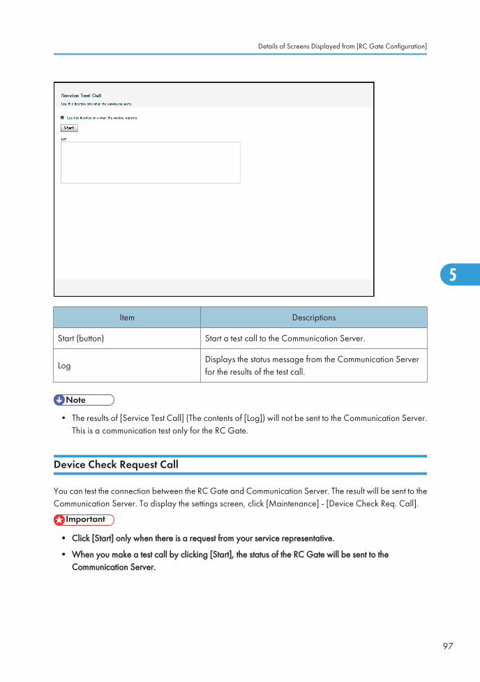
Item Descriptions
Start (button) Start a test call to the Communication Server.
LogDisplays the status message from the Communication Serverfor the results of the test call.
• The results of [Service Test Call] (The contents of [Log]) will not be sent to the Communication Server.This is a communication test only for the RC Gate.
Device Check Request Call
You can test the connection between the RC Gate and Communication Server. The result will be sent to theCommunication Server. To display the settings screen, click [Maintenance] - [Device Check Req. Call].
• Click [Start] only when there is a request from your service representative.
• When you make a test call by clicking [Start], the status of the RC Gate will be sent to theCommunication Server.
Details of Screens Displayed from [RC Gate Configuration]
97
5

Item Descriptions
Start (button) Start a test call to the Communication Server.
Extended Function Setting
You can increase the number of registerable device from 100 to 1,000. To display the settings screen,click [Maintenance] - [Extended Function Setting]. This item is displayed after the optional memory andstorage are installed.
5. Configuring the Details of the Registered Information
98
5

Item Descriptions
Extend the number of managed device(s)
Set whether to increase the number of registerable devices. Toincrease the number, select [Use] and restart the RC Gate.Once [Use] has been selected, the setting cannot be revertedto [Do not use]. To reset to [Do not use], contact your servicerepresentative.
Restart RC Gate
You can reboot the RC Gate during operation. To display the screen, click [Maintenance] - [Restart RCGate].
Details of Screens Displayed from [RC Gate Configuration]
99
5
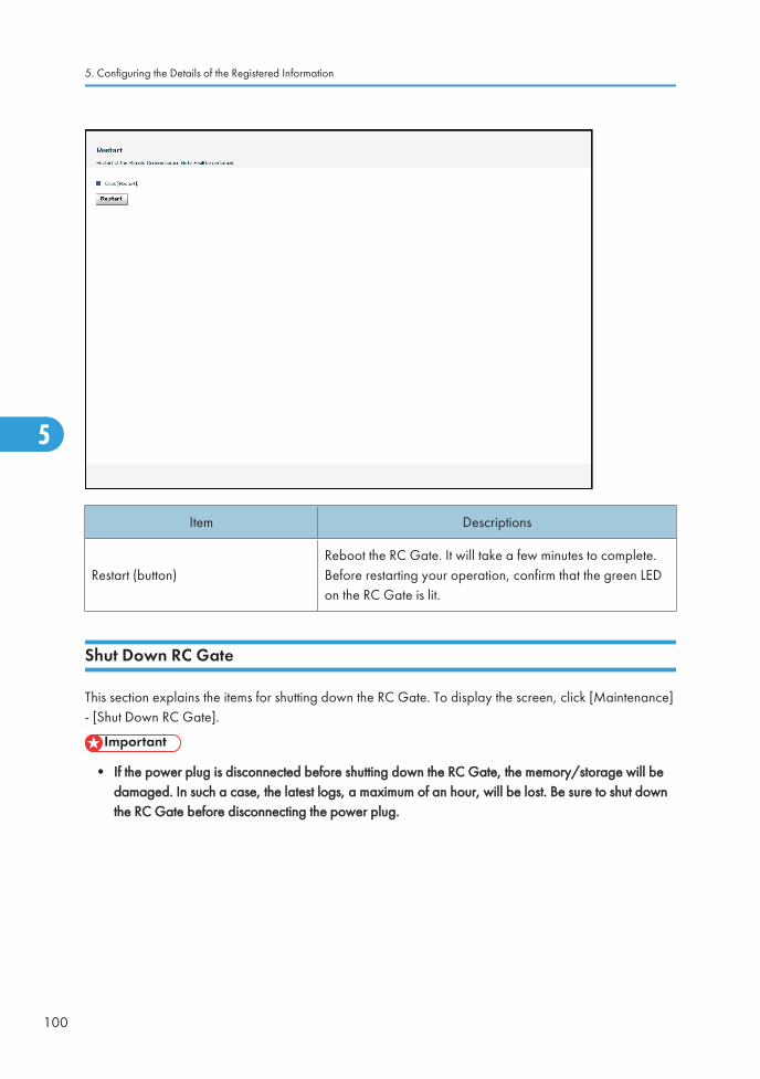
Item Descriptions
Restart (button)Reboot the RC Gate. It will take a few minutes to complete.Before restarting your operation, confirm that the green LEDon the RC Gate is lit.
Shut Down RC Gate
This section explains the items for shutting down the RC Gate. To display the screen, click [Maintenance]- [Shut Down RC Gate].
• If the power plug is disconnected before shutting down the RC Gate, the memory/storage will bedamaged. In such a case, the latest logs, a maximum of an hour, will be lost. Be sure to shut downthe RC Gate before disconnecting the power plug.
5. Configuring the Details of the Registered Information
100
5

Item Descriptions
Shut Down (button) Shut down the RC Gate.
Shut Down (dialog box)
This is displayed by clicking the [Shut Down] button. Click [OK]to start shutting down. Then [Shutting down RC Gate...] screenwill appear. Before you turn off the RC Gate, confirm that theorange LED stopped flashing, and the green and orange LEDsare lit.
• You can shut down the RC Gate by using the Shutdown button on the front of this equipment. Thisequipment is shut down by pressing and holding the button for five or more seconds.
Service Call
You can confirm the error codes and other information with this screen. To display the screen, click[Maintenance] - [Service Call]. Also, the screen will be automatically displayed when an error occurs onoperating [RC Gate Configuration]. When an error message appears on operating the RC Gate Monitor,click [Back] to display this screen.
Details of Screens Displayed from [RC Gate Configuration]
101
5
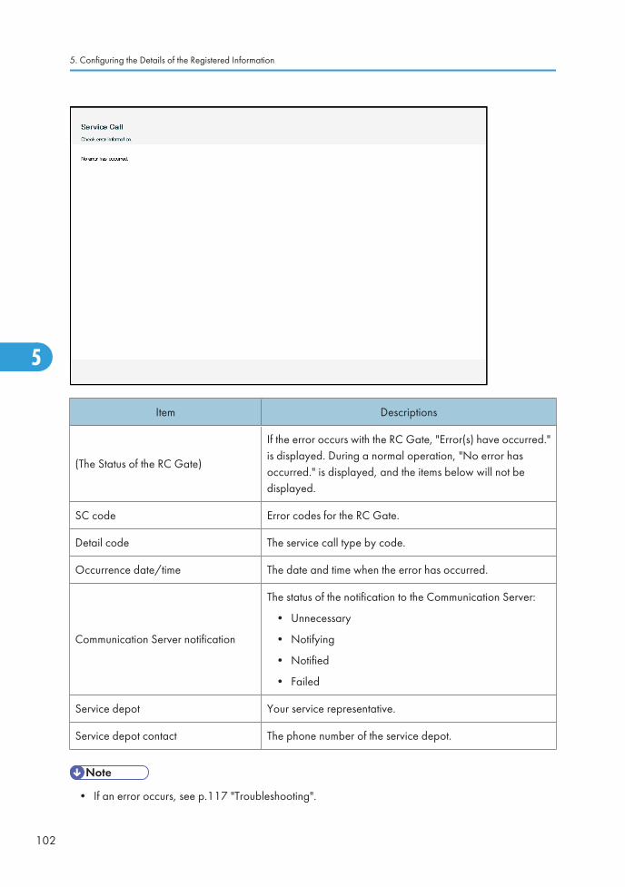
Item Descriptions
(The Status of the RC Gate)
If the error occurs with the RC Gate, "Error(s) have occurred."is displayed. During a normal operation, "No error hasoccurred." is displayed, and the items below will not bedisplayed.
SC code Error codes for the RC Gate.
Detail code The service call type by code.
Occurrence date/time The date and time when the error has occurred.
Communication Server notification
The status of the notification to the Communication Server:
• Unnecessary
• Notifying
• Notified
• Failed
Service depot Your service representative.
Service depot contact The phone number of the service depot.
• If an error occurs, see p.117 "Troubleshooting".
5. Configuring the Details of the Registered Information
102
5

System Status
You can confirm the system status of the RC Gate. To display the screen, click [Maintenance] - [SystemStatus]. The connection suspension e-mail will be sent to the administrator when the RC Gate is suspended.Also, click hyperlink to the URL in the e-mail which is sent to device administrator. The login page for theRC Gate Monitor will appear and the screen will appear immediately after the login page.
Item Descriptions
(Status of the RC Gate)Displays if the RC Gate is in operation or in suspension. If theRC Gate is operating normally, the items below will not bedisplayed.
Reason The major reason of suspension and action.
Date/Time of suspension The date and time when the suspension has occurred.
• When the system has suspended, check the following:
• The proxy settings, such as the password, have not changed.
• The Ethernet cable of the RC Gate has not been pulled out.
• The network devices, such as the power of a hub, are not off.
• If the items above have no problem, contact your service representative.
Details of Screens Displayed from [RC Gate Configuration]
103
5

User Account Settings
You can check the list of user accounts that can access the Web user interface of the RC Gate. To displaythe screen, click [Security] - [User Account Settings].
Administrator
Item Descriptions
User NameClick the user name to change the password for theadministrator.
Comment Comments about the user.
General User
Item Descriptions
User Name Click the user name to change the password for the user.
Comment Comments about the user.
Delete (button) Delete the login user name for general user.
Add (button)Displays "Add General User" screen. A maximum of 10 userscan be registered.
5. Configuring the Details of the Registered Information
104
5

Password
You can change the RC Gate Monitor login password. To display the settings screen, click [Security] -[User Account Settings] - [Change password], then click the applicable user name.
• Never use the default password. Specify a new password using 8 to 13 characters (ASCII character).
• You can use the following ASCII characters: space ! " # $ % & ' ( ) * + , - . / 0 1 2 3 4 5 6 7 8 9 : ;< = > ? @ A B C D E F G H I J K L M N O P Q R S T U V W X Y Z [ \ ] ^ _ a b c d e f g h i j k l m n op q r s t u v w x y z
• Change the passwords for the administrator and general users once every six months.
• Avoid using well known words or phrases, or repeated characters that can easily be guessed.
• Do not leave passwords written where they can be seen.
• New passwords become valid at next login.
Item Descriptions
Current password Enter the current password.
New Password Enter the new password.
Confirm password Enter the new password again to avoid typing error.
Details of Screens Displayed from [RC Gate Configuration]
105
5

Permissions
You can permit or deny service access by the customer engineer and firmware updates from theCommunication Sever. To display the screen, click [Security] - [Permissions].
• You can permit or deny the customer engineer's inspection and repair access to the RC Gate. If youselect [Do not permit], customer engineer access is denied until the administrator sets [Permit accessby service] to [Permit]. If you deny service access, the RC Gate may not be properly serviced. Formaintenance, contact a maintenance-specialist customer engineer.
Item Descriptions
Permit access by serviceSelect [Do not permit] to deny service access to the RC Gate.Select [Permit] to permit service access.
Authentication for Counter per User Retrieval
The counter information can be acquired and processed on a per-user basis for devices specified by theCommunication Server. To display the screen, click [Security] - [Authentication for Counter per UserRetrieval]. This item is displayed after the optional memory is installed.
5. Configuring the Details of the Registered Information
106
5

Authentication for Counter per User Retrieval from HTTPS (REST) Device
Item Descriptions
User name The user name for authentication.
Authentication password The password for authentication.
Certificate Usage Specify whether to use the certificate for authentication.
Certificate Select the certificate by entering the path or clicking [Browse].
Authentication for Counter per User Retrieval from HTTPS (SOAP) Device
Item Descriptions
User name The user name for authentication.
Authentication password The password for authentication.
Certificate Usage Specify whether to use the certificate for authentication.
Certificate Select the certificate by entering the path or clicking [Browse].
Retrieval Test Click [Confirmation] to display the retrieval test screen.
Details of Screens Displayed from [RC Gate Configuration]
107
5

Retrieval Test for Counter per User
Checks whether the per-user counter information can be obtained. To display the screen, click [Security]- [Authentication for Counter per User Retrieval] - [Confirmation].
Item Descriptions
IP AddressEnter a device's IP address to check whether it is possible toacquire per-user counter information for that device.
Test Result The result of the retrieval test.
Retrieval Test Click [Start] to start the retrieval test.
@Remote Service Function Limitation
You can suspend the @Remote Service function. To display the settings screen, click [Security] - [@RemoteService Function Limitation].
• To receive the latest RC Gate firmware updates from the Communication Server, set [Permit accessby service] to [Permit]. To use the default version, select [Do not permit].
5. Configuring the Details of the Registered Information
108
5

@Remote Service functions
Item Descriptions
@Remote Service functionsIf you select [Restrict], communication between theCommunication Server and devices is restricted.
Communication Server Requests
Item Descriptions
System firmware update by theCommunication Server
Select whether to allow system firmware to be updated by theCommunication Server.
Device firmware update by theCommunication Server
Select whether to allow device firmware to be updated by theCommunication Server.
Auto Discovery settings by theCommunication Server
Select whether to allow the Communication Server to use theAuto Discovery function.
Details of Screens Displayed from [RC Gate Configuration]
109
5

Security Log
The security log contains a list of security-related events, such as logins, logouts, and system changes. Todisplay the security log, click [Security] - [Security Log].
Click [Refresh] to obtain the latest log.
• Under the following operating conditions, about 28 log entries are generated each day. Because theminimum number of security log entries is 5,824, about 208 days of records can be stored in thesecurity log (5,824 divided by 28 = 208).
• The administrator and general users each log in and log out once a day.
• Device polling occurs once an hour.
• It is recommended that you check the security log at least once every 104 days (about 15 weeks) toensure that logs are not overwritten before you view them. Check the security log more frequently ifyour usage is greater than that given above.
• If the number of security log entries exceeds the maximum, new entries will overwrite the oldest entries,regardless of whether or not the log has been checked.
The following table explains the information that is displayed for one entry in the security log.
5. Configuring the Details of the Registered Information
110
5
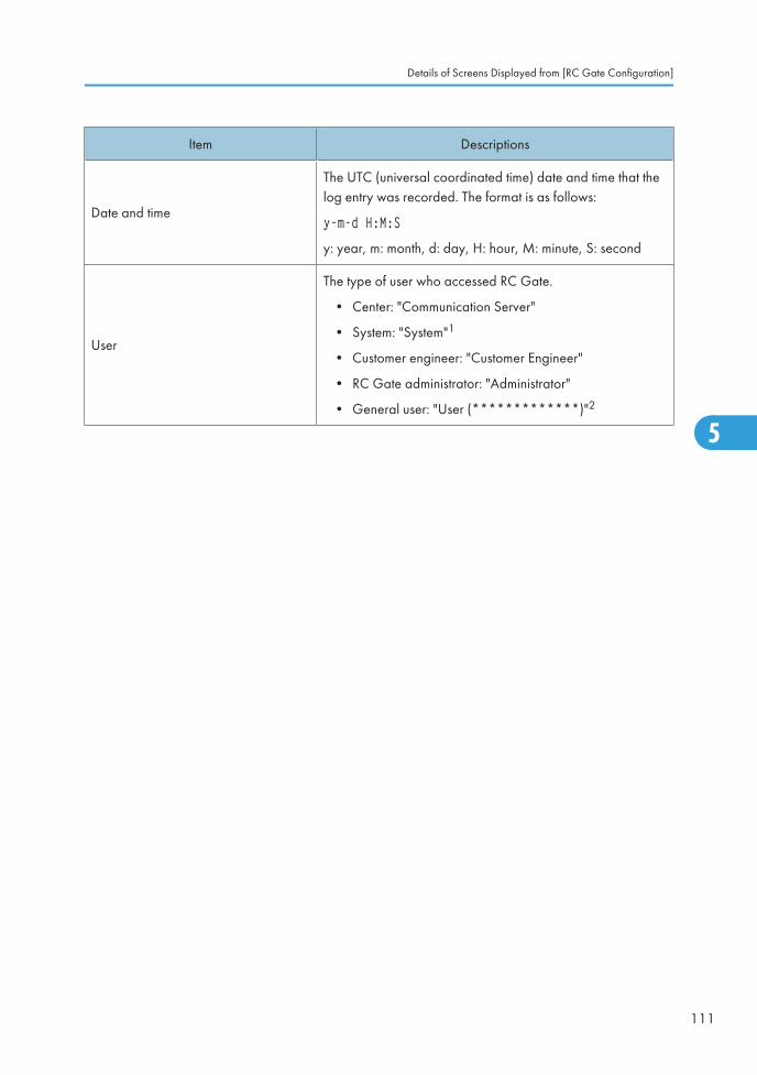
Item Descriptions
Date and time
The UTC (universal coordinated time) date and time that thelog entry was recorded. The format is as follows:
y-m-d H:M:S
y: year, m: month, d: day, H: hour, M: minute, S: second
User
The type of user who accessed RC Gate.
• Center: "Communication Server"
• System: "System"1
• Customer engineer: "Customer Engineer"
• RC Gate administrator: "Administrator"
• General user: "User (*************)"2
Details of Screens Displayed from [RC Gate Configuration]
111
5
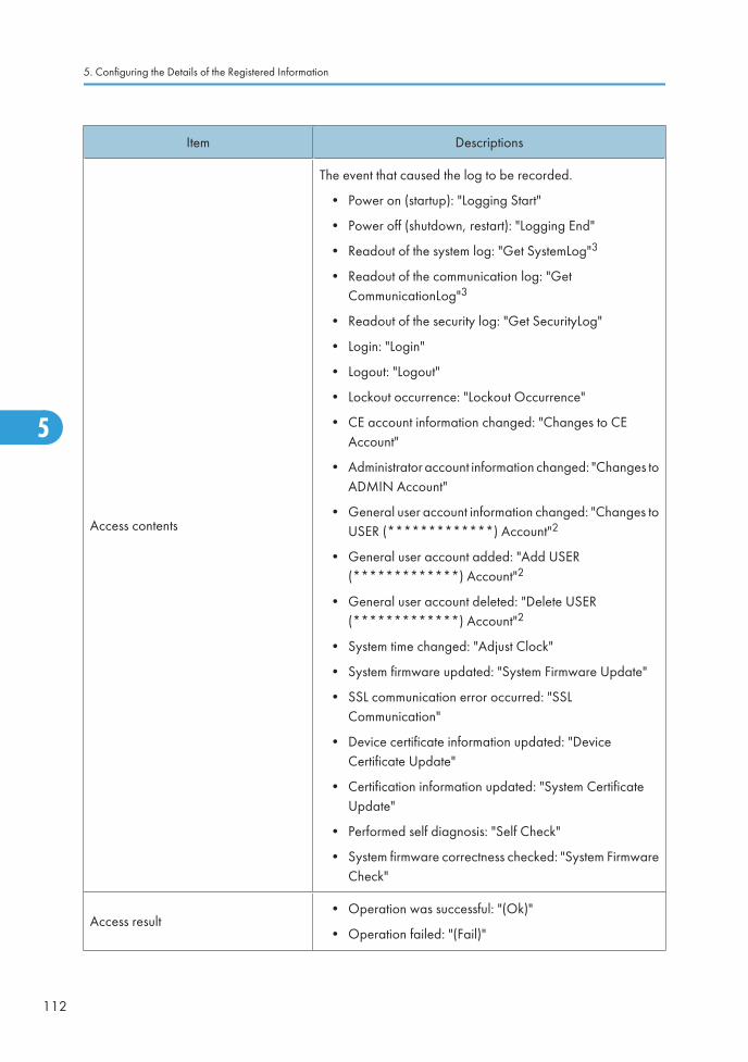
Item Descriptions
Access contents
The event that caused the log to be recorded.
• Power on (startup): "Logging Start"
• Power off (shutdown, restart): "Logging End"
• Readout of the system log: "Get SystemLog"3
• Readout of the communication log: "GetCommunicationLog"3
• Readout of the security log: "Get SecurityLog"
• Login: "Login"
• Logout: "Logout"
• Lockout occurrence: "Lockout Occurrence"
• CE account information changed: "Changes to CEAccount"
• Administrator account information changed: "Changes toADMIN Account"
• General user account information changed: "Changes toUSER (*************) Account"2
• General user account added: "Add USER(*************) Account"2
• General user account deleted: "Delete USER(*************) Account"2
• System time changed: "Adjust Clock"
• System firmware updated: "System Firmware Update"
• SSL communication error occurred: "SSLCommunication"
• Device certificate information updated: "DeviceCertificate Update"
• Certification information updated: "System CertificateUpdate"
• Performed self diagnosis: "Self Check"
• System firmware correctness checked: "System FirmwareCheck"
Access result• Operation was successful: "(Ok)"
• Operation failed: "(Fail)"
5. Configuring the Details of the Registered Information
112
5
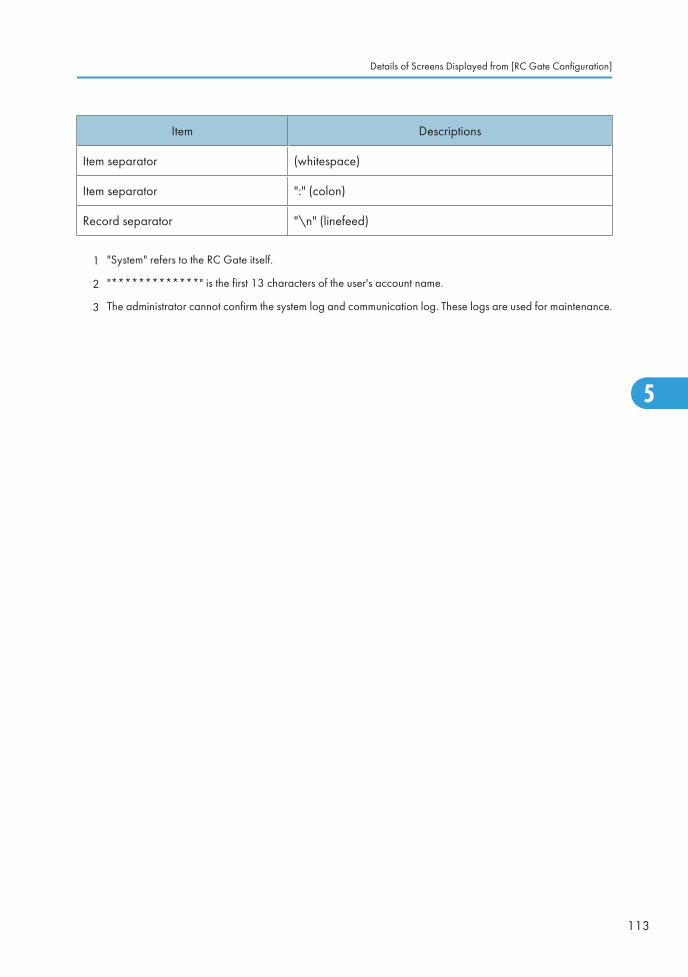
Item Descriptions
Item separator (whitespace)
Item separator ":" (colon)
Record separator "\n" (linefeed)
1 "System" refers to the RC Gate itself.
2 "*************" is the first 13 characters of the user's account name.
3 The administrator cannot confirm the system log and communication log. These logs are used for maintenance.
Details of Screens Displayed from [RC Gate Configuration]
113
5
5. Configuring the Details of the Registered Information
114
5

6. Appendix
LCD MessagesThe following table shows the messages that will be displayed on the LCD.
First Line
Message Description
Warming Up The system boot process is being performed.
Pre-shpmt Status The device has not completed the pre-shipment review.
Not Set Up The @Remote service registration has not been completed.
NormalThe @Remote service registration has completed and the RCGate is operating normally.
Off-lineThe communication with the Communication Server has beensuspended.
Error A system error has occurred.
Call Service RepAn error has occurred, and reboot has failed after trying it forthe specified number of times.
Not in ServiceThe @Remote service has been limited due to @Remote ServiceFunction Limitation.
Reboot The system reboot is being performed.
Shutdown The system completion process is being performed.
Second Line
Message Description
SC:System error has occurred, or the system has stopped due toabnormal conditions. Error status code will be displayed inmaximum of 6-digit numbers.
Cable Disconnect The cable has been disconnected.
802 Server Error Connection with the authentication server has been failed.
802 Auth.Failure Authentication has been failed.
115
6

Message Description
DHCPServerError DHCP setting is enabled but failed to obtain IP address.
--------------- No message to be displayed.
LAN port IP addressIP address of the LAN port is displayed except when abovemessages are displayed.
6. Appendix
116
6
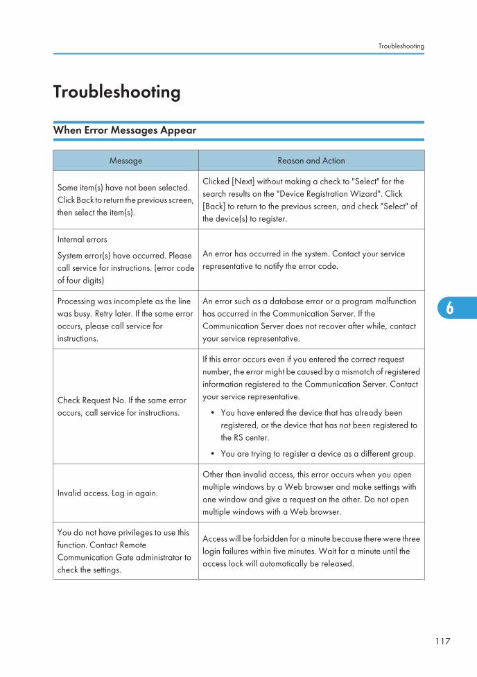
Troubleshooting
When Error Messages Appear
Message Reason and Action
Some item(s) have not been selected.Click Back to return the previous screen,then select the item(s).
Clicked [Next] without making a check to "Select" for thesearch results on the "Device Registration Wizard". Click[Back] to return to the previous screen, and check "Select" ofthe device(s) to register.
Internal errors
System error(s) have occurred. Pleasecall service for instructions. (error codeof four digits)
An error has occurred in the system. Contact your servicerepresentative to notify the error code.
Processing was incomplete as the linewas busy. Retry later. If the same erroroccurs, please call service forinstructions.
An error such as a database error or a program malfunctionhas occurred in the Communication Server. If theCommunication Server does not recover after while, contactyour service representative.
Check Request No. If the same erroroccurs, call service for instructions.
If this error occurs even if you entered the correct requestnumber, the error might be caused by a mismatch of registeredinformation registered to the Communication Server. Contactyour service representative.
• You have entered the device that has already beenregistered, or the device that has not been registered tothe RS center.
• You are trying to register a device as a different group.
Invalid access. Log in again.
Other than invalid access, this error occurs when you openmultiple windows by a Web browser and make settings withone window and give a request on the other. Do not openmultiple windows with a Web browser.
You do not have privileges to use thisfunction. Contact RemoteCommunication Gate administrator tocheck the settings.
Access will be forbidden for a minute because there were threelogin failures within five minutes. Wait for a minute until theaccess lock will automatically be released.
Troubleshooting
117
6

If Problems Described in Error Messages Persist
Contact your service representative if problems described in error messages persist.
When the Office or Devices are Moved
Registration to the Communication Server is required in the following cases. Contact your servicerepresentative.
• When your office has moved (The RC Gate has moved.)
• When managed devices are moved (Except Auto Discovery)
• When managed devices are newly connected (Except Auto Discovery)
• When managed devices are deleted (Except Auto Discovery)
To Return the RC Gate
Contact your service representative when you no longer require the RC Gate. Your service representativewill collect it and, for security purposes, will erase all information it has stored.
Error Codes
Code Message
0001 Cannot connect to the network. Check the LAN cable connection.
0002Cannot connect to the Network. If DHCP is enabled, check the network settings.If the same error occurs, call service for instructions.
0003Cannot authenticate IEEE802.1x. Confirm with the network administrator. If thesame error occurs, please call service for instructions.
0004Cannot authenticate IEEE802.1x. Confirm the settings of IEEE802.1xauthentication. If the same error occurs, please call service for instructions.
0005Cannot connect to the Network. Check DNS on the network settings. If the sameerror occurs, call service for instructions.
0006 Cannot connect to the network. Confirm the proxy server name and port number.
0007Cannot connect to the Network. Check proxy user name, proxy password orproxy domain name.
6. Appendix
118
6
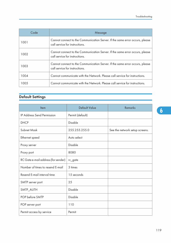
Code Message
1001Cannot connect to the Communication Server. If the same error occurs, pleasecall service for instructions.
1002Cannot connect to the Communication Server. If the same error occurs, pleasecall service for instructions.
1003Cannot connect to the Communication Server. If the same error occurs, pleasecall service for instructions.
1004 Cannot communicate with the Network. Please call service for instructions.
1005 Cannot communicate with the Network. Please call service for instructions.
Default Settings
Item Default Value Remarks
IP Address Send Permission Permit (default)
DHCP Disable
Subnet Mask 255.255.255.0 See the network setup screens.
Ethernet speed Auto select
Proxy server Disable
Proxy port 8080
RC Gate e-mail address (for sender) rc_gate
Number of times to resend E-mail 3 times
Resend E-mail interval time 15 seconds
SMTP server port 25
SMTP_AUTH Disable
POP before SMTP Disable
POP server port 110
Permit access by service Permit
Troubleshooting
119
6
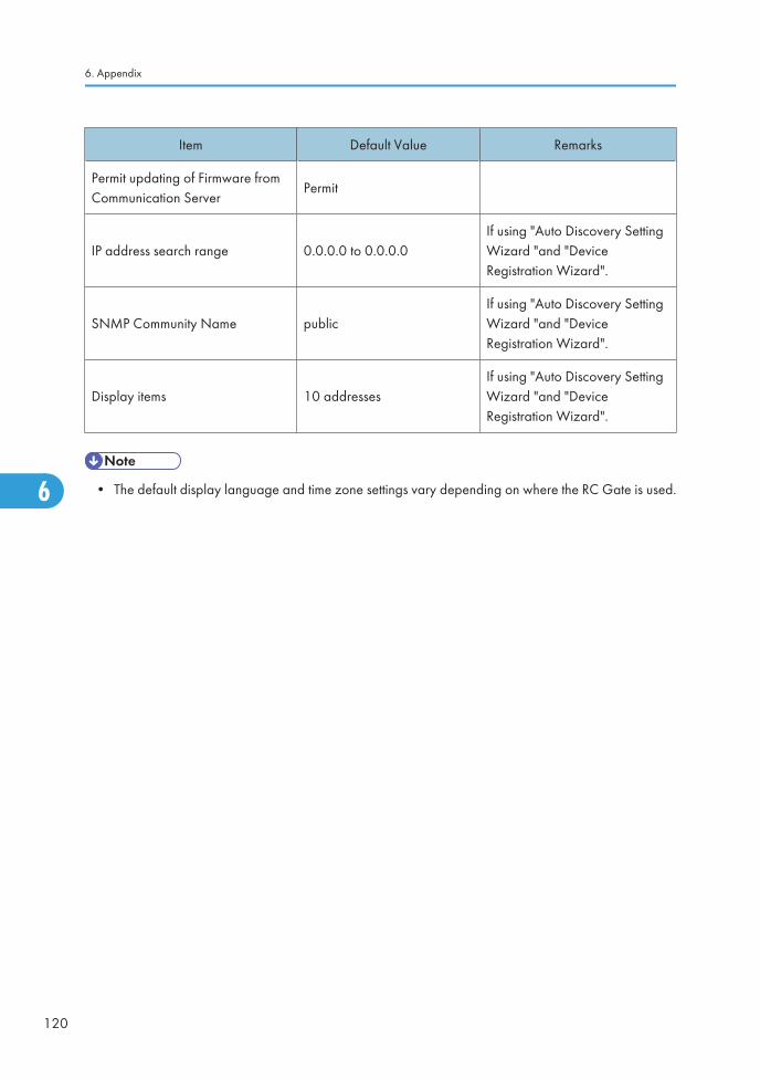
Item Default Value Remarks
Permit updating of Firmware fromCommunication Server
Permit
IP address search range 0.0.0.0 to 0.0.0.0If using "Auto Discovery SettingWizard "and "DeviceRegistration Wizard".
SNMP Community Name publicIf using "Auto Discovery SettingWizard "and "DeviceRegistration Wizard".
Display items 10 addressesIf using "Auto Discovery SettingWizard "and "DeviceRegistration Wizard".
• The default display language and time zone settings vary depending on where the RC Gate is used.
6. Appendix
120
6

Specifications for the Main UnitItem Descriptions
Type Box type
InterfaceEthernet interface × 2
(10BASE-T or 100BASE-TX)
Options• Remote Communication Gate Memory 1000
• Remote Communication Gate Storage 1000
IndicatorLED 2 (Error Status, Power)
Display LCD (16 digits × 2 lines)
Protocols TCP/IP, SNMP, HTTP, SOAP, SMTP, DHCP
Managing DevicesDigital multifunction devices, copiers, and printers correspondent tothe service
Maximum Number of Devices tobe Supported
• Controlled devices registered to the Communication Server
100 devices (1,000 devices when the optional memory andstorage have been installed)
• Auto Discovery
1,000 devices (including the devices registered to theCommunication Server on the network)
Environment 10 - 32 °C (50 - 89.6 °F), 15 - 80 %RH
Power
• For Users in Countries Outside of North America:
220-240 Vac, 50/60 Hz, 2.5 A or more
• For Users in North America:
120 Vac, 60 Hz, 3.0 A or more
Power Consumption 20 W or less
Dimensions Width 253 mm (10") /Depth 160 mm (6.3") /Height 48 mm (1.9")
Weight 800 g (1.8 lbs)
Specifications for the Main Unit
121
6

Information about Installed SoftwareThe following is a list of the software included in this equipment:
• WPASupplicant
• OpenSSL
• busybox
• dosfstools
• glibc
• knopflerfish
• corelib
• as3crypto
• as3httpclientlib
• SNMP4J
• kxml2
• Apache commons
• kSOAP2
• linux-kernel
You can check the information about license and copyright of each software by clicking [License andCopyright Information] in the login page.
6. Appendix
122
6

INDEX
@Remote Service Function Limitation.................108
@Remote Service Registration Wizard........17, 21,22
A
Access Prohibited IP Address.........................17, 75Auto Discovery Setting Wizard................................29, 33CSV file.......................................................................36, 58Device Registration Wizard..............................41, 47, 53
Administrator..........................................................16
Authentication for Counter per User Retrieval.......................................................................................106
Auto Discovery......................................................25Basic Settings.....................................................................77Edit Range..........................................................................80Protocol Settings.................................................................78
Auto Discovery Setting Wizard........17, 25, 26, 30
B
Back........................................................................13
Basic settings..........................................................63
C
Call Report Record................................................87
Call Report Record(s)............................................17
Common Management.........................................90
Communication ServerDevice registration.............................................................38RC Gate registration..........................................................22
CSV file............................................................35, 56Access prohibited IP address....................................29, 34Auto Discovery...........................................................28, 33Device registration.............................42, 47, 48, 53, 54
D
Date settings...........................................................65
Default settings....................................................119
Details.....................................................................17
Details (device)......................................................84
Device Check Request Call..................................97
Device Registration Wizard........17, 37, 38, 44, 50
Display (LCD).........................................................13
E
Settings...............................................................................72Test......................................................................................75
Error codes..........................................................118
Error messages....................................................117
Extended device search setting............................83
F
Front........................................................................12
G
General user..........................................................17
H
Host nameCSV file...............................................................................57Searching...........................................................................50
HTTP proxy server.................................................22
HTTP Proxy settings................................................70
I
IEEE802.1x Authentication settings.....................68
Indicator (LAN port)..............................................13
Installed software................................................122
IP addressAuto Discovery...................................................................26CSV file.......................................................................35, 56Searching...........................................................................38
L
LAN port.................................................................13
LAN port indicator.................................................13
LCD display............................................................13
LCD messages.....................................................115
LEDError status (red).................................................................12Power (green)....................................................................12
M
Manuals...................................................................2Memory..................................................................15
N
Network segmentAuto Discovery...................................................................30CSV file.......................................................................36, 57Searching...........................................................................44
123
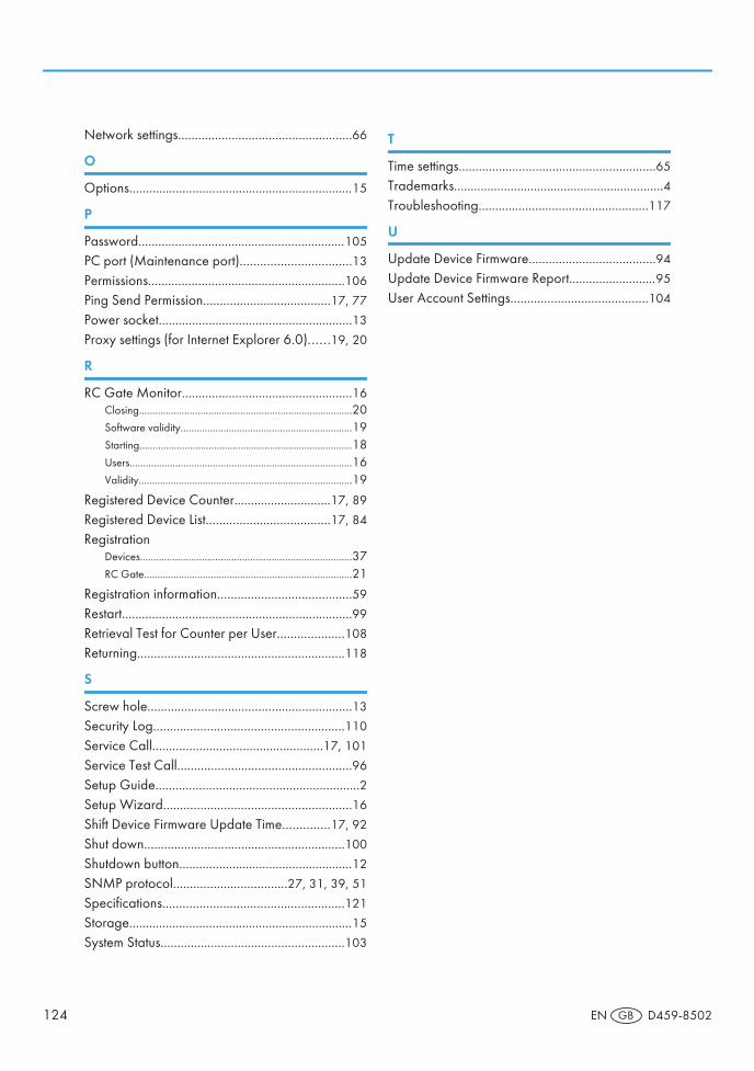
Network settings....................................................66
O
Options...................................................................15
P
Password..............................................................105
PC port (Maintenance port).................................13
Permissions...........................................................106
Ping Send Permission......................................17, 77
Power socket..........................................................13
Proxy settings (for Internet Explorer 6.0)......19, 20
R
RC Gate Monitor...................................................16Closing................................................................................20Software validity................................................................19Starting................................................................................18Users...................................................................................16Validity................................................................................19
Registered Device Counter.............................17, 89
Registered Device List.....................................17, 84
RegistrationDevices...............................................................................37RC Gate..............................................................................21
Registration information........................................59
Restart.....................................................................99
Retrieval Test for Counter per User....................108
Returning..............................................................118
S
Screw hole.............................................................13
Security Log.........................................................110
Service Call...................................................17, 101
Service Test Call....................................................96
Setup Guide.............................................................2Setup Wizard........................................................16
Shift Device Firmware Update Time..............17, 92
Shut down............................................................100
Shutdown button....................................................12
SNMP protocol..................................27, 31, 39, 51
Specifications......................................................121
Storage...................................................................15
System Status.......................................................103
T
Time settings...........................................................65
Trademarks...............................................................4Troubleshooting...................................................117
U
Update Device Firmware......................................94
Update Device Firmware Report..........................95
User Account Settings.........................................104
124 EN GB D459-8502

Copyright © 2009

Operating Instructions
D459-8502EN GB