operating instructions mettler toledo spider bc counting
TRANSCRIPT

SPIDER BC
SPIDER BC
Operating Instructions
METTLER TOLEDOSpider BC Counting Scales

SPIDER BC
Overview of your Spider BC scale
1
34
7
10
Rear view
Overview
Display
Keypad
32333435
36 37 38 39 40 41
5
16
6
8
9
141312
2
11
15
±#ÇOnOff
≤
BG/Net :≤
;
≤
<Ref 10 Ref n
OptAuto
Com 231 231
Pcs%kg100
OK10050500
%
171819
202122
23
24 25 26 27 28
2930
31
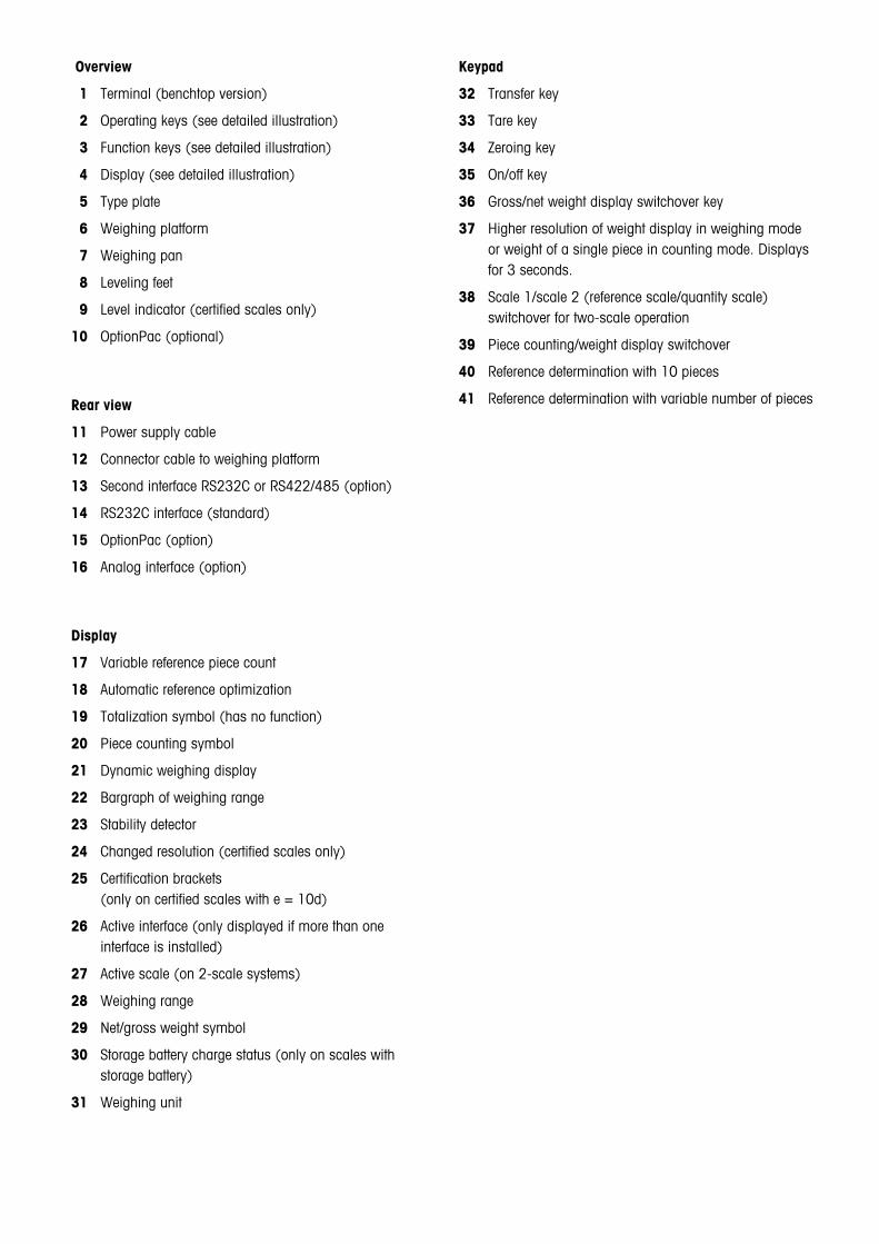
Overview
1 Terminal (benchtop version)
2 Operating keys (see detailed illustration)
3 Function keys (see detailed illustration)
4 Display (see detailed illustration)
5 Type plate
6 Weighing platform
7 Weighing pan
8 Leveling feet
9 Level indicator (certified scales only)
10 OptionPac (optional)
Rear view
11 Power supply cable
12 Connector cable to weighing platform
13 Second interface RS232C or RS422/485 (option)
14 RS232C interface (standard)
15 OptionPac (option)
16 Analog interface (option)
Display
17 Variable reference piece count
18 Automatic reference optimization
19 Totalization symbol (has no function)
20 Piece counting symbol
21 Dynamic weighing display
22 Bargraph of weighing range
23 Stability detector
24 Changed resolution (certified scales only)
25 Certification brackets(only on certified scales with e = 10d)
26 Active interface (only displayed if more than oneinterface is installed)
27 Active scale (on 2-scale systems)
28 Weighing range
29 Net/gross weight symbol
30 Storage battery charge status (only on scales withstorage battery)
31 Weighing unit
Keypad
32 Transfer key
33 Tare key
34 Zeroing key
35 On/off key
36 Gross/net weight display switchover key
37 Higher resolution of weight display in weighing modeor weight of a single piece in counting mode. Displaysfor 3 seconds.
38 Scale 1/scale 2 (reference scale/quantity scale)switchover for two-scale operation
39 Piece counting/weight display switchover
40 Reference determination with 10 pieces
41 Reference determination with variable number of pieces

Contents
4
Contents
1 Setting up the scale ....................................................................................................................................... 6
1.1 Important ....................................................................................................................................................... 61.2 Unpacking and checking the delivered items ...................................................................................................... 61.3 Safety and environment .................................................................................................................................... 61.4 Selecting a location and leveling the scale ......................................................................................................... 71.5 Connecting the power supply ............................................................................................................................ 7
2 Weighing ....................................................................................................................................................... 8
2.1 Switching on/off and setting to zero ................................................................................................................... 82.2 Simple weighing ............................................................................................................................................. 82.3 Weighing with tare .......................................................................................................................................... 92.4 Weighing with 2-scale systems ........................................................................................................................ 92.5 Dynamic weighing ........................................................................................................................................ 10
3 Piece counting ............................................................................................................................................. 11
3.1 Counting pieces into a container ..................................................................................................................... 113.2 Counting pieces out of a container .................................................................................................................. 123.3 Automatic reference optimization ..................................................................................................................... 123.4 Adding mode ................................................................................................................................................ 133.5 Piece counting with two-scale systems ............................................................................................................ 13
4 The menu .................................................................................................................................................... 14
4.1 Overview and operation ................................................................................................................................. 144.2 Calling up the menu and entering the password ................................................................................................ 144.3 Menu overview .............................................................................................................................................. 154.4 Scale settings (SCALE) ................................................................................................................................... 174.4.1 Adjust/calibrate scale (SCALE –> Cal) .............................................................................................................. 174.4.2 Display accuracy and weighing unit (SCALE –> Display) ................................................................................... 184.4.3 Automatic taring (SCALE –> A-Tare) ................................................................................................................ 184.4.4 Automatic zero point correction (SCALE –> A-Zero) ........................................................................................... 184.4.5 Automatic save of tare and zero values (SCALE –> Restart) ................................................................................ 194.4.6 Aadaptation to environmental conditions and weighing mode (SCALE –> Filter) ................................................... 194.4.7 Reset scale settings to factory settings (SCALE –> Reset) ................................................................................... 194.5 Application settings (APPLICATION) ................................................................................................................. 204.5.1 Settings for piece counting (APPLICATION –> Count) ......................................................................................... 204.5.2 Activating the dynamic weighing function (APPLICATION –> Dynamic) ................................................................ 204.5.3 Reset application settings to factory settings (APPLICATION –> Reset) ................................................................. 214.6 Terminal settings (TERMINAL) ......................................................................................................................... 214.6.1 Standby, energy-saving mode, and display backlighting (TERMINAL –> Device) .................................................. 214.6.2 Password for menu access (TERMINAL –> Access) ........................................................................................... 224.6.3 Reset terminal settings to factory settings (TERMINAL –> Reset) .......................................................................... 22

Contents
5
4.7 Configure interfaces (COMMUNICATION) .......................................................................................................... 234.7.1 Operating mode of interface (COMMUNICATION –> Mode) ................................................................................. 234.7.2 Communication parameters (COMMUNICATION –> Parameters) ......................................................................... 244.7.3 Settings for printed reports (COMMUNICATION –> Definition String) ..................................................................... 254.7.4 Inserting line feeds into the report (COMMUNICATION –> Add Line Feed) .............................................................. 264.7.5 Reset interface settings to factory settings (COMMUNICATION –> Reset) ............................................................... 264.8 Diagnosis and printout of menu settings (DIAGNOSTICS) ................................................................................... 264.8.1 Checking the keyboard (DIAGNOSTICS –> Keyboard) ........................................................................................ 274.8.2 Checking the display (DIAGNOSTICS –> Display) .............................................................................................. 274.8.3 Display serial number (DIAGNOSTICS –> SNR) ................................................................................................. 274.8.4 Printing the menu settings (DIAGNOSTICS –> List) ............................................................................................ 274.8.5 Reset all menu settings to the factory settings (DIAGNOSTICS –> Reset All) .......................................................... 284.9 Saving the settings and quitting the menu (End ) .............................................................................................. 28
5 Additional important information ................................................................................................................... 29
5.1 SICS interface commands ............................................................................................................................... 295.1.1 Preconditions for communication between scale and PC .................................................................................... 295.1.2 SICS commands supported by the scale .......................................................................................................... 295.1.3 Scale-specific SICS command for defining the report header ............................................................................... 295.1.4 Network operation via the optional RS422/485 interface .................................................................................... 305.2 Warning and error messages .......................................................................................................................... 305.3 Sample reports .............................................................................................................................................. 315.4 Cleaning instructions ..................................................................................................................................... 31
6 Technical data, interfaces, and accessories ................................................................................................... 32
6.1 General data and delivered items .................................................................................................................... 326.2 Type codes and model-specific data ................................................................................................................ 336.2.1 Type codes ................................................................................................................................................... 336.2.2 Model-specific data ....................................................................................................................................... 336.3 Dimensions and weights ................................................................................................................................ 346.3.1 Terminal ....................................................................................................................................................... 346.3.2 Weighing platforms ....................................................................................................................................... 346.4 RS232C and RS422/485 interfaces ................................................................................................................ 356.5 Analog option ............................................................................................................................................... 366.6 Accessories .................................................................................................................................................. 376.7 Declaration of conformity ............................................................................................................................... 386.8 Safety tests ................................................................................................................................................... 39

Chapter 1: Setting up the scale
6
1 Setting up the scalePlease read these operating instructions carefully and follow them exactly! If you find that any items are missing or incorrect, or ifyou have any other problems with your scale, please contact your authorized METTLER TOLEDO representative.
1.1 Important
Various different models of the Spider scale terminal are available. Only the benchtop model is described in these instructions. Ifyou ordered a wall- or stand-mount terminal, please refer to the installation instructions delivered separately. The OptionPac (specialequipment) can contain a number of options, such as additional interfaces or a storage battery. If you ordered an OptionPac it willhave been configured at the factory with the options you requested and fastened below the terminal.
1.2 Unpacking and checking the delivered items
Remove the scale and accessories from the packaging and check the delivered items:
– Terminal and weighing plaform with installed weighing pan and level indicator (certified scales only)
– Open-end wrench for leveling the weighing platform
– Operating instructions (this document)
– Special accessories (if any) as per packing list
1.3 Safety and environment
For safe and environmentally harmless operation of your scale, observe the following instructions:
Do not use the scale in hazardous environments (unless it is specially marked).
Although the Spider scale is protected to IP65, it must not be used in environmentswhere there is a corrosion hazard. Never flood the scale or immerse it in liquids!
If the power supply cable is damaged, the scale must not be used. Check the cableregularly.
Do not open the weighing platform or terminal since this will void the guarantee. Donot use rigid objects to clean inside the weighing platform.
Treat the scale with care, it is a precision instrument. Avoid knocking the weighing panor placing excessively heavy loads on it.
If the Spider scale will be used in food processing areas: Those parts of the scale whichmay come into contact with food have a smooth surface and are easy to clean. Thematerials used do not shatter and contain no harmful substances. In food processingareas, it is advisable to use the protective cover (accessory). This must be regularlycleaned like the scale itself. A damaged or heavily soiled protective cover must bereplaced immediately.
When disposing of the scale, observe the applicable environmental regulations. If thescale is fitted with a storage battery, note that the battery contains heavy metals andmust therfore not be disposed of as normal waste! Observe local regulations for disposalof environmentally harmful substances.
IP65

Chapter 1: Setting up the scale
7
1.4 Selecting a location and leveling the scale
The proper location can influence the accuracy of the weighing results!
Choose a stable, vibration-free flat surface. The surface must be able to bear the weightof the fully loaded scale safely.
Pay attention to environmental conditions:
– No direct sunlight
– No strong drafts (e.g. from fans or air conditioning)
– No excessive temperature fluctuations
Adjust the scale horizontally by turning the leveling feet, then use the open-end wrenchsupplied to tighten the locknuts of all the leveling feet so as to prevent unintentionalmovement.
On certified scales, the weighing platform has a level indicator. The air bubble must liewithin the inner circle of the indicator.
Note: The level indicator can be mounted in a different position. Undo the two fasteningscrews and move the level indicator to one of the positions provided (drilled holes inthe weighing platform).
Major changes of geographical location
Each scale is adjusted by the manufacturer for the local gravitational conditions (geovalue). If there is a major change of geographical location, this adjustment must becorrected by a service technician. Certified scales must also be recertified in accordancewith local national regulations for certification.
=000∆
Before connecting the power supply, check that the voltage printed on the back of thescale is the same as the local power supply. If it is not, do not connect the scale, andcontact your authorized METTLER TOLEDO representative.
If the voltage is correct, connect the plug on the power cable to the power supply.
After the scale has been connected, it performs a display test. When the display showszero, the scale is ready for operation. For maximum precision, after installing the scalecarry out an adjustment/calibration (Chapter 4.4.1). Important: Certified scales mustbe adjusted by an authorized laboratory. Ask your authorized representative.
Scales which have an OptionPac with built-in storage battery can operate undernormal conditions for approx. 30 hours disconnected from the power supply (withbacklighting turned off and no accessories connected). As soon as the power supplyis interrupted, the scale automatically switches over to battery operation. When poweris restored, the scale automatically switches back to power supply operation. Thebattery symbol indicates the current charge status of the storage battery (1 segment =approx. 25% capacity). If the symbol flashes, the storage battery must be recharged(8 hours minimum). If work continues while recharging, it takes longer. The storagebattery is protected against ovecharging, so the scale can be permanently connectedto the power supply without problem.
1.5 Connecting the power supply

Chapter 2: Weighing
8
2 WeighingThis chapter explains how you switch the scale on and off, adjust the zero setting, tare the scale, carry out weighings, and recordweighing results.
2.1 Switching on/off and setting to zero
You switch the scale on and off by pressing the «On/Off» key.
After it has been switched on, the scale carries out a display test. When the weightdisplay appears, the scale is ready for weighing and is automatically set to zero.Note: The «Ç» key can be used to set the scale to zero at any time.
2.2 Simple weighing
Place the weighing sample on the pan.
The bar graph in the lower part of the display shows how much of the weighing range isalready used and how much is still available (in % of the nominal capacity of the scale).
Wait until the stability detector (small ring at left-hand edge of display) goes off and thenread the weighing result.
You can use the «:» key in control mode to display the weighing result at higherresolution. After a few seconds, the weight display automatically returns to normal.Note: Control mode is not available if the highest resolution has already been set in themenu (Chapter 4.4.2). On certified scales, in control mode the weight is displayedwithout a weighing unit.
You can use the «±» key to transmit the weighing result via the interface to a peripheraldevice (printer, computer) (see Chapter 5.3 for sample report).
% l l l l l l l l l l l 0 50 100
• (65∆
(649∆
OnOff
:
±

Chapter 2: Weighing
9
Place the empty weighing container or the packaging material on the weighing pan andpress the «#» key to tare the scale.
The zero display and the “NET” (net weight) symbol appear. Note: If the automatic tarefunction is active (Chapter 4.4.3), you need not press the «#» key, since the firstweight added is taken to be the tare (“T” flashes in the display until the tare is added).
Place the weighing sample on the weighing pan and ...
... read the result (net weight of the weighing sample).
You can use the «≤ BG/Net» key at any time to switch the display between the net andgross weight. After the key is pressed, the display shows the gross weight (“B/G”) fora few seconds and then changes back automatically to the net weight (“NET”).
Note: The tare weight is retained until either a new tare is determined, or the scale is setto zero or switched off.If the automatic taring function is active, the tare is automatically cleared when weighingis completed and the weighing pan emptied; the scale is then ready for the next taringand weighing.
=00∆ NET
"46∆ NET
2.4 Weighing with 2-scale systems
If a second scale is connected, the weighing can be carried out on either the Spider or the second scale.
≤
BG/Net
"47∆B/G
The scale symbol in the upper right corner of the display indicates the currently activescale (;1 or ;2).
The «≤ ;» key switches between the two scales.
All the keys of the Spider terminal act on the currently active scale. Second scales whichsupport MT-SICS can be set to zero and tared from the Spider terminal.
≤
;
ç36∆; 1
2(55∆; 2
2.3 Weighing with tare

Chapter 2: Weighing
10
2.5 Dynamic weighing
‹ 2(55∆For unstable weighing objects (e.g. animals) the dynamic weighing function withautomatic or manual start can be activated (section 4.5.2). If the dynamic weighingfunction is active, the mouse symbol appears at the bottom edge of the display.
With dynamic weighing the scale measures 56 weighing values in 4 seconds andcalculates their mean value.
With dynamic weighing and automatic start the measurement begins automatically assoon as there is a change in weight.
With dynamic weighing and manual start the measurement is started by touching the«±» key.
During dynamic weighing, horizontal segments appear in the display, after which thecalculated mean value is displayed. The star symbol at the left-hand edge indicates thatthe result is a calculated one. To start a new weighing cycle, the scale must be unloaded.
Note: Only activate the dynamic weighing function to weigh unstable goods. In normaloperation the standard weighing function yields more accurate results more rapidly.

Chapter 3: Piece counting
11
○
○
○
○
○
3 Piece countingYour scale has a number of powerful piece counting functions which can be activated in the menu (see Chapter 4.5.1). This chapterdescribes the functions which have been activated at the factory.
3.1 Counting pieces into a container
Place the empty container on the scale and tare with the «#» key.
Note: If the automatic taring function is active (Chapter 4.4.3), you need not press the«#» key, because the scale registers the tare weight automatically as soon as thecontainer is placed on the weighing pan.
Before your scale can be used for counting parts, it must know the average peice weight(the so-called reference). To determine this, you must place a certain number of thepieces to be weighed on the weighing pan. The scale determines their total weight anddivides it by the number of pieces (the so-called reference number of pieces). Basedon this calculated average piece weight, counting can than be carried out.
Select the reference number of pieces:
– When exactly 10 pieces have been placed on the pan, press the «Ref 10» key .
– If a different number of pieces has been placed on the weighing pan, press the«Ref n» key and hold it down until the respective number of pieces is displayed abovethe key. At the factory, piece numbers of 1, 2, 5, 15, 20, 25, 30, 50, 100 and “no”(«Ref n» key inactive) are provided. The variable reference number of pieces isretained until you change it again.
When the «Ref 10» or «Ref n» key is released, the scale determines the reference(average piece weight) and then indicates the number of pieces.
Place more pieces in the container until the desired number is reached.
Once a reference has been determined, you can use the «≤ <» key to switch backand forth between the number of pieces and the weight display at any time.
You can use the «±» key to transmit the piece counting result via the interface to aperipheral device (printer, computer) (for sample report see Chapter 5.3).
5
Ref 10
Ref n
100
10 πNET
≤
<
±

Chapter 3: Piece counting
12
3.2 Counting pieces out of a container
There are only a few points of difference between counting pieces out of a weighing container and counting them in.
Place the full container on the weighing pan and then press the «#» key to tare thescale.
Determine reference:
Remove the reference number of pieces from the weighing container and ...
... then press the «Ref 10» or «Ref n» key to determine the reference, as described inthe previous chapter.
The scale displays the number of pieces removed, preceded by a minus sign.
- 10 πNET
#
Ref 10 Ref n
3.3 Automatic reference optimization
Piece counting with automatic reference optimization gives more accurate results. This function can be switched on and off in themenu (Chapter 4.5.1). Automatic reference optimization is switched on at the factory.
No action is required during operation for automatic reference optimization and itfunctions both when “Counting in” (Chapter 3.1) and when “Counting out” (Chapter3.2). The “Auto Opt” symbol in the display indicates that automatic referenceoptimization is switched on.
Each time you place additional parts on the scale, it optimizes automatically. You donot have to press a key to perform optimization. At each optimization the message“Ref Opt” appears briefly and the new total number of pieces is then displayed.
Note: At each automatic reference optimization the average piece weight (reference) isre-calculated. Since the additional pieces increase the basis for the calculation, thereference also becomes more accurate. However, automatic optimization only func-tions if the number of additional pieces placed on the scale is not greater than the numberalready on the weighing pan.
Auto Opt
rEFOPt
Chapter 3: Piece counting
13
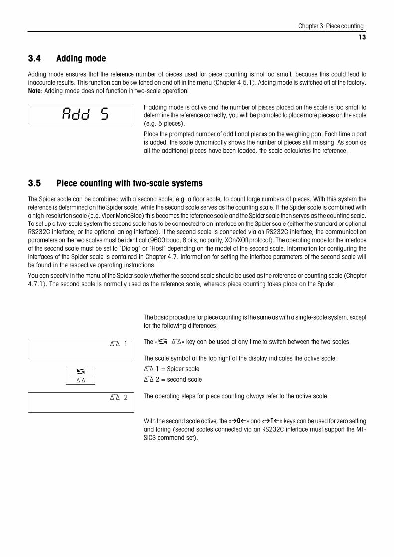
3.5 Piece counting with two-scale systems
The Spider scale can be combined with a second scale, e.g. a floor scale, to count large numbers of pieces. With this system thereference is determined on the Spider scale, while the second scale serves as the counting scale. If the Spider scale is combined witha high-resolution scale (e.g. Viper MonoBloc) this becomes the reference scale and the Spider scale then serves as the counting scale.To set up a two-scale system the second scale has to be connected to an interface on the Spider scale (either the standard or optionalRS232C interface, or the optional anlog interface). If the second scale is connected via an RS232C interface, the communicationparameters on the two scales must be identical (9600 baud, 8 bits, no parity, XOn/XOff protocol). The operating mode for the interfaceof the second scale must be set to “Dialog” or “Host” depending on the model of the second scale. Information for configuring theinterfaces of the Spider scale is contained in Chapter 4.7. Information for setting the interface parameters of the second scale willbe found in the respective operating instructions.
You can specify in the menu of the Spider scale whether the second scale should be used as the reference or counting scale (Chapter4.7.1). The second scale is normally used as the reference scale, whereas piece counting takes place on the Spider.
The basic procedure for piece counting is the same as with a single-scale system, exceptfor the following differences:
The «≤ ;» key can be used at any time to switch between the two scales.
The scale symbol at the top right of the display indicates the active scale:
; 1 = Spider scale
; 2 = second scale
The operating steps for piece counting always refer to the active scale.
With the second scale active, the «Ç» and «#» keys can be used for zero settingand taring (second scales connected via an RS232C interface must support the MT-SICS command set).
; 1
; 2
3.4 Adding mode
Adding mode ensures that the reference number of pieces used for piece counting is not too small, because this could lead toinaccurate results. This function can be switched on and off in the menu (Chapter 4.5.1). Adding mode is switched off at the factory.Note: Adding mode does not function in two-scale operation!
If adding mode is active and the number of pieces placed on the scale is too small todetermine the reference correctly, you will be prompted to place more pieces on the scale(e.g. 5 pieces).
Place the prompted number of additional pieces on the weighing pan. Each time a partis added, the scale dynamically shows the number of pieces still missing. As soon asall the additional pieces have been loaded, the scale calculates the reference.
Add 5
≤
;

Chapter 4: The menu
14
4 The menuThe menu can be used to change the settings for the scale and to activate functions, thereby allowing the scale to be adapted toindividual weighing neeeds.
Important: To avoid incorrect operation of the scale in normal use, the menu can be protected with a password. The scale differentiatesbetween a user and a supervisor. When the scale leaves the factory, the entire menu can be accessed by both user and supervisor.We therefore recommend you to define your own supervisor password as soon as you set up the scale (Chapter 4.6.2). Thislimits access by the user to a small number of menu items (calibration, and settings for energy-saving mode and backlighting).
4.1 Overview and operation
Chapter 4.3 contains a complete overview of the menu and all the possible settings.
4.2 Calling up the menu and entering the password
COdE
±
Press the «±» key and hold it down until the prompt to enter the password appears.
User: No password required, just press the «±» key.
Supervisor: Enter password (sequence of keystrokes) immediately and confirm withthe «±» key, otherwise after a few seconds the scale returns to weighing mode. If anincorrect password is entered, the menu cannot be called up.Note: When the scale leaves the factory no supervisor password is defined, so whenthe password is requested, just press the «±» key.
If the password entered is correct, the first block of the menu appears (“SCALE”).
▼
○ ○ ○ ○ ○
Request password
CodE
=.00∆
Weighing mode
Chapter 4.2
Enter password
- - - -
▼
Operator Supervisor
▼
Quit menu
End
Diagnosis
d1AGNOS
Interfaces
COMMUN1
Terminal
tERM1NL
Applications
APPL1C
Scale
SCALE
▼ ▼ ▼ ▼ ▼
▼
▼
▼
Chapter 4.4▼
Chapter 4.5▼
Chapter 4.6▼
Chapter 4.7▼
Chapter 4.8 Chapter 4.9▼
Press «±» key and hold down (call up menu)
Press «±» key briefly (“Yes”)
Press «#» key briefly (“No”)
• «On/Off» key jumps direct to end of menu (“End”)
• «Ç» navigates backward through the menu• If no key is operated for 3 min. the menu is closed (without saving changes
to settings)
▼▼
▼

Chapter 4: The menu
15
4.3 Menu overview
Operation
Press «±» key (“Yes”)
Press «#» key (“No”)
«On/Off» key jumps direct to the end of the menu (“End”)
«Ç» navigates backward through the menu
0.00 ∆
ãããã
±
±
CodE
0.00 ∆
SCALE 1 CAL
SCALE 2
d1SPLAY
RESOLUã 0 ã
6.000∆0.0001∆
0.05∆
Un1t
Un1t
Un1t
Un1t
RESEt
UN1t
2.000∆
donE
Un1t
kg
lb
g
oz
t
AãtARE
OFF
ON
Aã2ERO
ON
OFF
REStARt
OFF
ON
FiLtER
V1bRAt
UN1VEr
dOS1NG
PROCESS
LOW
MEd
H1GH
SCALESURE?
APPL1C
Add.MOdE
OFF
ON
REF OPt
ON
OFF
dYNAM1C
SURE?
RESEtCOUNt
tERM1NL
SLEEP
OFF
ON
ACCESS
SURE?
RESEtdEV1CE
PWROFF
YES
NO
b.L1GHt
SUPERV1
ENtER.C
ãããã
REtYPE.C
ãããã
On
OFF
3
2
3
21
21
* * *
*
*
3 3
*
*
*
*
*
4
5
OFF
AUtO
MAnuAL
*
Scale
Applications
Terminal

Chapter 4: The menu
16
Menu (continued)
* Factory setting
1) Available settings depend on model.
2) Factory setting depends on model.
3) Not available on certified scales.
4) Not available on scales with storage battery.
5) Not available on scales driven from power supply (without storagebattery).
6) Not available for analog option.
7) Only available for COM2 if analog option is not installed or is deactivated.
8) For second scale connected to a COM interface, only available if analogoption is not installed or is deactivated.
9) Only available for analog option.
10) Only available for “Print” and “AutoPrint” operating modes.
11) Not available for COM2.
12) Only available if “Handshake” is set to “Net 422” or “Net 485”.
13) Only available if analog option is installed and active.
0.00 ∆
CON 1
OPt1ON
MOdE
CON 2
PARAMEt
bAUd
CONNUN1
H.SHAKE
nEt.Addr
L1NE.FNtPrint
A.Print
CONt1NU
d1ALOG
2nd.d1SP
rEF
bULK
300
600
1200
2400
4800
9600
19200
38400
7 EVEN
7 nonE
8 nonE
7 odd
HONOFF
nEt 422
nEt 485
NO
0
MULt1
S1NGLE
FORMAt
StdArd
31
L1NE 1
L1NE 20
CUStOM
NOt.USEd
HEAdEr
SCALE.NO
GROSS
tArE
NEt
APII
rEF Ct
PCS
StARLN
CrLF
F FEEd
4
0
Add LF
rEF
bULK
bYPASS
MOdE
SURE?
rSt.CON.
PAritY
dEFStr
KboARd d1SPLAY
d1AGNOS
PUSH 1
PUSH 10
SURE?
rESEt.ALSNR
0000000
; 1
LiSt; 1
SNR
0000000
; 2
LiSt; 2
EndSAVE
6*
6
6
6
7
7
67
8
8
9
*
*
*
11
11
12
*
13 13
*
10 10
CONt.OLd67
d1AL.OLd67
8 odd
8 EVEN
Interfaces
Diagnosis
Quit menu

Chapter 4: The menu
17
▼
○
○
○
○
○
○
○
○
○
○
SCALE ▼
▼SCALE 1
SCALE 2▼
4.4 Scale settings (SCALE )
Display Explanation
Scale settings:
Settings and functions for Spider scale
Settings and functions for second scale
Note: The “SCALE 1/SCALE 2 ” selection only appears if the analog option is installed.
Functions and settings:
Adjust/calibrate scale ––> Chapter 4.4.1
Display accuracy and weighing unit ––> Chapter 4.4.2
Automatic taring ––> Chapter 4.4.3
Automatic zero point correction ––> Chapter 4.4.4
Automatic storage of tare and zero values ––> Chapter 4.4.5
Adaptation to environmental conditions/weighing mode ––> Chapter 4.4.6
Reset scale settings to factory settings ––> Chapter 4.4.7
▼
▼
CAL
- 0 -
&000∆
▼
▼
▼
%000∆
"000∆
▼
Calibrating/adjusting the scale (weighing pan must be empty).Not available on certified scales!
Scale determines the zero point, display flashes (no confirma-tion required).
Scale prompts for calibration weight.
Change calibration weight if desired (available values dependon scale).
Place selected weight on pan and confirm.
Calibration is successfully completed....
... scale returns automatically to weighing mode.
4.4.1 Adjust/calibrate scale (SCALE –> Cal )
Display Explanation
donE
▼
=00∆

Chapter 4: The menu
18
▼
▼▼
▼
▼
▼
▼
▼▼
d1SPLAY
RESOLU
oz
kg
lb
t
UN1t
▼
▼
▼
▼
▼▼
=0001∆
=05∆
▼
4.4.2 Display accuracy and weighing unit (SCALE –> Display)
Display Explanation
Block can only be accessed by supervisor.
Display accuracy (resolution):
Setting values and factory setting depend on model.
On certified scales, resolutions which deviate from the scaledefinition are displayed without the weighing unit and witha star symbol (weighing result does not correspond tocalibrated resolution). On dual-range balances resolutionsmarked with “I<–>I 1/2” are spread over two weighingranges (e.g. B 2 x 3,000d).
Weighing unit (factory setting according to type plate):
Kilogram
Ounce (not availble on certified scales)
Pound (not available on certified scales)
Ton (metric ton)
Gramg
OFF
On
A - tARE
▼
▼
▼ ▼
Block can only be accessed by supervisor.
Automatic taring function switched off (factory setting).
Automatic taring function switched on. The first weight placed on the scale is inter-preted as the tare.
4.4.3 Automatic taring (SCALE –> A-Tare)
Display Explanation▼
Can only be accessed by supervisor. Not available on certified scales.
Auto zero switched on (factory setting).
Auto zero switched off (display can be set to zero manually with the «Ç» key).
On
OFF
A - 2ERO
▼
▼
▼ ▼
4.4.4 Automatic zero point correction (SCALE –> A-Zero)
Display Explanation

Chapter 4: The menu
19
Resets all scale settings to the factory settings (applies only to selected scale, “SCALE 1”or “SCALE 2”). This block can only be accessed by the supervisor.
Confirm resetting or cancel.▼
SURE?
RESEt ▼
▼
4.4.7 Reset scale settings to factory settings (SCALE –> Reset )
Display Explanation
▼
▼▼
▼
Block can only be accessed by supervisor. Not available on certified scales.
Automatic save switched off (factory setting).
Automatic save switched on, last tare and zero values are saved and are availableagain after a power outage or switching off.
OFF
On
REStARt
▼
▼
▼
▼
4.4.5 Automatic save of tare and zero values (SCALE –> Restart )
Display Explanation
▼▼
FiLtEr
V1bRAt
dOS1NG
UN1VEr
PROCESS
▼
▼
▼
MEd
H1GH
▼
▼
4.4.6 Aadaptation to environmental conditions and weighing mode (SCALE –> Filter )
Display Explanation
Block can only be accessed by supervisor.
Environmental conditions (vibration adapter):
Normal environmental conditions (“medium”): scale operatesat medium speed (factory setting).
Unstable environment (“high”): scale operates more slowly butis less sensitive to external influences.
Very stable and stable enviroment (“low”): scale operates veryquickly but is more sensitive to external influences.
Weighing mode (weighing process adapter):
Universal setting for all weighing types and normal weighinggoods (factory setting).
Dispensing liquids or powdery substances.
LOW
▼
▼
▼
▼

Chapter 4: The menu
20
▼▼
▼▼
▼
Application settings: can only be accessed by supervisor!
Settings for piece counting ––> Chapter 4.5.1
Activate dynamic weighing function ––> Chapter 4.5.2
Reset application settings to factory settings ––> Chapter 4.5.3
APPL1C ▼
▼
COUNt
dYNAMIC
4.5 Application settings (APPLICATION)
Display Explanation
RESEt
Adding mode (does not function in two-scale operation):
Adding mode switched off (factory setting).
Adding mode switched on (when piece counting, ensures thatthe reference quantity used is not too small, see Chapter 3.5).
Reference optimization:
Reference optimization switched on (factory setting), increas-es piece counting accuracy (see Chapter 3.4).
Reference optimization switched off.
▼▼
Count
Add.MOdE
OFF
ON
REF OPt
▼
▼
▼
OFF
ON
▼
▼
▼
▼ ▼
4.5.1 Settings for piece counting (APPLICATION –> Count )
Display Explanation
This function facilitates weighing unstable weighing goods (e.g. animals).
Dynamic weighing function switched off (factory setting).
Dynamic weighing function with automatic start switched on (for notes on use, seeChapter 2.5).
Dynamic weighing function with manual start switched on (for notes on use, seeChapter 2.5).
▼
OFF
AUtO
dYNAM1C
▼
▼
▼
MAnuAL
▼
▼
4.5.2 Activating the dynamic weighing function (APPLICATION –> Dynamic)
Display Explanation

Chapter 4: The menu
21
▼▼
▼
Only the “Device” block is available to the user!
Standby, energy-saving mode, and display backlighting ––> Chapter 4.6.1
Password for menu access ––> Chapter 4.6.2
Reset terminal settings to factory settings ––> Chapter 4.6.3
▼▼
▼
tERM1NL ▼
▼
dEV1CE
ACCESS
RESEt
4.6 Terminal settings (TERMINAL)
Display Explanation
Can be accessed by user!
Standby (only for scales operated from power supply):
Standby switched off, display permanently activated (factorysetting).
Standby switched on. If there is no activity for 3 minutes, thedisplay and backlighting are deactivated (“SLEEP”). They arereactivated when a key is pressed or the weight is changed.
Energy saving mode (for battery-operated scales only):
Energy saving mode active. If there is no activity for 3 minutes,the scale is switched off (factory setting).
Energy saving mode inactive, scale does not switch off auto-matically.
Display backlighting:
Backlighting switched on (factory setting). Battery-operatedscales: switches off automatically after 5 seconds.
Backlighting switched off.
▼▼
dEV1CE
SLEEP
NO
YES
PWROFF
▼
▼
▼
OFF
ON
▼
▼
▼
▼
▼
4.6.1 Standby, energy-saving mode, and display backlighting (TERMINAL –> Device)
Display Explanation
▼
OFF
On
b.L1GHt
▼
▼
Resets all application settings to the factory settings.
Confirm resetting or cancel.▼
SURE?
RESEt ▼
▼
▼
4.5.3 Reset application settings to factory settings (APPLICATION –> Reset )
Display Explanation

Chapter 4: The menu
22
Can only be accessed by supervisor!
Define supervisor password:
Prompt to enter password.
Enter password (min. 1, max. 4 characters) and confirm with«±».
Important: The «±» key cannot be used as part of the pass-word because it terminates the input! If «±» is pressed im-mediately after the entry prompt, the existing password iscleared. The user then has complete access to the menu again.The «Ç» key can only be used in combination with at leastone other key!
Re-enter the password and confirm with «±».
Resets all terminal settings to the factory settings. Only the settings in the “Device”block are reset, not the password for menu access.
Confirm resetting or cancel.▼SURE?
RESEt ▼
▼
▼
4.6.3 Reset terminal settings to factory settings (TERMINAL –> Reset )
Display Explanation
▼
▼
ACCESS
SUPERV1
▼
▼
ENtER.C
- - - -
▼
▼
REtYPE.C
▼
4.6.2 Password for menu access (TERMINAL –> Access)
Display Explanation

Chapter 4: The menu
23
Configures the scale interfaces: can only be accessed by supervisor!
Standard interface COM1 (RS232C or RS422/485).
Optional interface COM2 (RS232C).
Analog option (only if analog option installed).
Settings:
Operating mode of interface ––> Chapter 4.7.1
Communication parameters ––> Chapter 4.7.2
Settings for printed reports ––> Chapter 4.7.3
Insert line feeds into printed reports ––> Chapter 4.7.4
Reset interface settings to factory settings ––> Chapter 4.7.5
Manual data output on printer («±» key). Factory setting.
Automatic output of stable results on printer (for series weighings).
Continuous output of all weight values via the interace. Not available for COM2 ifanalog option active!
Bidirectional communication using MT-SICS commands (to control scale from a PC).Not available for COM2 if analog option active!
Same as “Continuous” (see above), but with 2 fixed blanks before the unit (compatiblewith Spider 1/2/3).
Same as “Dialog” (see above), but scale sends 2 fixed blanks before the unit (com-patible with Spider 1/2/3).
Connects a second display. Not available for COM2 if analog option active!
Second scale serves as reference scale.
Second scale serves as counting scale.
Deactivates the analog option (if present). If the analog option is not deactivated, the“Ref” and “Bulk” settings are no longer available for COM1, and only the “Print” and“A. Print” operating modes are available for COM2!
COMMUN1 ▼
▼COM 1
COM 2
OPt1ON
▼
4.7 Configure interfaces (COMMUNICATION )
Display Explanation
▼A.Print
CONt1NU
d1ALOG
2nd.d1SP
rEF
MOdE
Print▼
▼
▼
▼
▼
▼
▼
▼
▼▼
CONt.OLd
d1AL.OLd
bULK
bYPASS
4.7.1 Operating mode of interface (COMMUNICATION –> Mode)
Display Explanation

Chapter 4: The menu
24
Not available for analog option. Parameters on the connecteddevice (printer, PC, second display) must be set to the samevalues:
Interface data transmission rate:
300 baud – 38400 baud. Factory setting = 2400 baud.
Number of data bits and parity:
7 data bits, even parity (factory setting)
8 data bits, odd parity
8 data bits, even parity
7 data bits, no parity
8 data bits, no parity
7 data bits, odd parity
Factory setting depends on operating mode of interface.
Transmission protocol:
Xon/Xoff protocol (factory setting).
Network operation according to RS422 standard via optionalRS422/485 interface (COM1). Not available for COM2.
Network operation according to RS485 standard via optionalRS422/485 interface (COM1). Not available for COM2.
No communication protocol.
Network address (only available for “Net 422” and “Net 485”,see Chapter 5.1.4 for notes on network operation).
Available network addresses 0 – 31.
▼▼
▼▼
▼
PARAMEt
nEt 422
nEt 485
NO
▼
▼
▼
▼
▼
▼
▼▼
▼▼
31
300
38400
▼
▼
▼
▼
▼
▼
▼
▼
8 EVEN
▼
▼
▼
7 nonE
8 nonE
7 odd
8 odd
▼▼
▼
0
nEt.Addr
H.SHAKE
HONHOFF
PAritY
7 EVEN
bAUd
4.7.2 Communication parameters (COMMUNICATION –> Parameters)
Display Explanation

Chapter 4: The menu
25
▼
Only available for “Print” and “A.Print” operating modes (Chap-ter 4.7.1).
Report formatting:
Each value on the report is printed on a separate line (factorysetting).
Several values are printed on one line.
Data to be reported:
Standard report (factory setting) containing report header,gross, net, and tare weight (if present). For piece counting, alsoreference piece weight, number of reference pieces, and resultof piece counting.
Defines customized report:
Defines the values to be reported on up to 20 report lines.
The following settings are available for each line:
Report line not used (factory setting).
Report header (Chapter 5.1.3).
Scale number (for two-scale systems only)
Gross weight
Tare weight
Net weight
Average piece weight
Reference quantity
Piece counting result (“Pieces”)
Line of stars (“Starline”)
Line feed (for empty line)
Form feed for label printer.
▼
▼▼
▼
▼
○
○
S1NGLE
MULt1
StdArd
CUStOM
dEFStr
L1NE.FMt
FORMAt
GROSS
tArE
NEt
APW
rEF Ct
PCS
StARLN
CrLF
F FEEd
HEAdEr
NOt.USEd
L1NE 20
L1NE 1
SCALE.NO
▼
▼
▼
▼
▼
▼
4.7.3 Settings for printed reports (COMMUNICATION –> Definition String)
Display Explanation

Chapter 4: The menu
26
▼▼
Inserts additional line feeds at the end of the report. On printers with tear-off edge (e.g.“Sprinter” printer) the paper can be fed forward far enough for the report to be torn off.Only available for “Print” and “A.Print” operating modes (Chapter 4.7.1):
4 additional line feeds at end of report (factory setting).
No additional line feeds at end of report.
▼
4
0
SURE?
Add LF
rSt.COM1
rSt.COM2
▼
▼
▼
▼
▼▼
▼
▼
4.7.4 Inserting line feeds into the report (COMMUNICATION –> Add Line Feed)
Display Explanation
4.7.5 Reset interface settings to factory settings (COMMUNICATION –> Reset)
Display Explanation
Resets all settings in the “COMMUNICATION” menu block to the factory settings. Resettingonly affects the selected interface (COM1 or COM2). Not available for analog option.
Confirms or cancels resetting. After confirmation the scale uses the factory settingsagain.
Can only be accessed by supervisor!
Check keyboard ––> Chapter 4.8.1
Check display ––> Chapter 4.8.2
Display serial number ––> Chapter 4.8.3
Print menu settings ––> Chapter 4.8.4
Reset all menu settings to factory settings ––> Chapter 4.8.5
Note: If a second weighing platform is connected via the analog option, separate menublocks are displayed for its serial number (“SNR ;2”) and to print out its menusettings (“List ;2”).
▼▼
▼
d1AGNOS ▼
▼
KboARd
d1SPLAY
SNR
4.8 Diagnosis and printout of menu settings (DIAGNOSTICS)
Display Explanation
▼LiSt
▼rESEt.AL

Chapter 4: The menu
27
Press all 10 keys in sequence. If a key is functioning, the scale jumps to the next key.The keys are numbered as follows:
▼
○
○
○
○
○
○
○
○
▼
KboARd
PUSH 1
PUSH 10
▼
4.8.1 Checking the keyboard (DIAGNOSTICS –> Keyboard)
Display Explanation
○ ○ ○ ○ ○ ○ ○ ○ ○ ○
1098765
1 432
The scale displays the functioning segments. Check whether all segments are visible(compare with illustration on first inside page of these instructions).
▼
▼
d1SPLAY ▼
4.8.2 Checking the display (DIAGNOSTICS –> Display)
Display Explanation
Serial number of Spider scale (max. 7 characters). If a second weighing platform isconnected to the analog option, an additional menu block (“SNR ;2”) appears withits serial number.▼
▼
▼
1234567
SNR; 1
4.8.3 Display serial number (DIAGNOSTICS –> SNR )
Display Explanation
Menu settings for the Spider scale are output on a printer (see sample printout inChapter 5.3). If a second weighing platform is connected to the analog option, anadditional menu block (“List ;2”) appears for printing the settings of the secondscale.
▼
▼
▼LiSt; 1
4.8.4 Printing the menu settings (DIAGNOSTICS –> List )
Display Explanation
SOFTWARE VER 22-2.00SNR :1234567METROLO :NO APPrSCAL.TYP :2MULT.RNBAS.UNIT :kgSCL.CAP1 :30.00 kgRESOL.1 :0.01 kgSCL.CAP2 :60.00 kgRESOL.2 :0.02 kg
OptAuto
Com 231 231
Pcs%kg100
OK10050500
%

Chapter 4: The menu
28
Resets all menu settings to the factory settings. Caution: All the individual settingsare lost except for the supervisor password (“TERMINAL” menu block), the calib-ration data and the settings in the “COMMUNICATION” block!
Confirm resetting or cancel.▼
SURE?
rESEt.AL ▼
▼
▼
4.8.5 Reset all menu settings to the factory settings (DIAGNOSTICS –> Reset All)
Display Explanation
You can go directly to this menu block from any point in the menu by using the «On/Off» key!
Save the changed settings or cancel.▼
SAVE
End ▼
▼
▼
4.9 Saving the settings and quitting the menu (End )
Display Explanation
=00∆
Chapter 5: Additional important information
29
5 Additional important informationIn this chapter you will find information about the interface commands, error messages, and cleaning your scale.
5.1 SICS interface commands
The Spider scale supports the METTLER TOLEDO Standard Interface Command Set (MT-SICS). You can use MT-SICS commandsto configure, interrogate, and operate the scale from a PC via the RS232C or optional RS422/485 interface.
5.1.1 Preconditions for communication between scale and PC
– The scale must be connected to the RS232C interface of a PC by a suitable cable (Chapter 6.6).
– The interface of the scale must be set to “Dialog” mode (Chapter 4.7.1).
– The PC must have a terminal program (e.g. “Hyper Terminal”) installed on it.
– The communication parameters (data transmission rate, bits, and parity) in the terminal program must be set to the same valuesas on the scale (Chapter 4.7.2).
5.1.2 SICS commands supported by the scale
– All SICS Level 0 (“I0”, “I1”, “I2”, “I3”, “I4”, “S”, “SI”, “SIR”, “Z”, “ZI”, “@”) and SICS Level 1 (“D”, “DW”, “K”, “SR”, “T”, “TA”,“TAC”, “TI”) commands. The additional “SFIR” command corresponds to the SICS Level 0 “SIR” command but transmits a greaternumber of data records per unit of time (while doing so, the display of the Spider scale is no longer active).
– The following commands from SICS Level 2R Standard are implemented: “SU”, “SIU”, “SIRU” and “SRU”.
– The “PW” command from SICS Level 3R Standard is supported.
– Special command “P130” for price display in auxiliary display (for details refer to document no. 21300758).
– SQC14 command “XD12” switches operating mode of interface between “Print” and “Dialog”.
The “I0” command can be used to inquire the supported commands.
You will find detailed information about the interface commands in the “MT SICS Reference Manual” (ME-705184).
Besides the standard commands, there are also scale-specific SICS commands which support specific characteristics of theproduct. These commands are not listed in the “MT SICS Reference Manual” but in the documentation of the specific scale. Your Spiderscale currently supports only one scale-specific command for defining the report header.
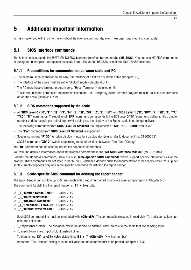
5.1.3 Scale-specific SICS command for defining the report header
The report header can contain up to 5 lines each with a maximum of 24 characters (see sample report in Chapter 5.3).
The command for defining the report header is I31_x. Example:
I31_1_"Mettler-Toledo GmbH" <CR><LF>I31_2_"Heuwinkelstrasse" <CR><LF>I31_3_"CH-8606 Naenikon" <CR><LF>I31_4_"Telephone 01 944 22 11" <CR><LF>I31_5_"Internet www.mt.com" <CR><LF>
– Each SICS command line must be terminated with <CR><LF>. The command is executed immediately. To make corrections, re-enter the entire line.
– “_” represents a blank. The quotation marks must also be entered. They indicate to the scale that text is being input.
– To insert blank lines, input a blank instead of text.
– To inquire line: I31_x <CR><LF>; delete line: I31_x_"" <CR><LF> (x = line number).
– Important: The “Header” setting must be activated for the report header to be printed (Chapter 4.7.3).

Chapter 5: Additional important information
30
5.1.4 Network operation via the optional RS422/485 interface
You can use the optional RS422/485 interface to network up to 32 scales. In network operation the scale must be addresed by thehost computer before commands can be transmitted and weighing results received. Addressing is done with the control character<ESC> (hex. 1B) followed by the address (in the range from hex. 30... 3F). Following this, the desired SICS command is transmittedand terminated with <CR> (hex. 0D) and <LF> (hex. 0A). This transfers control of the bus to the scale, which then sends its addressto the host as confirmation. After that, the scale sends the answer to the command, followed by <CRLF>. By doing this it returns controlof the bus to the host.
Example: The host addresses the scale with hex address 3A.
The host transmits command (e.g. “SI”). The command is terminated with <CRLF> andcontrol of the bus is transferred to the scale. Note: <ESC> deletes a command alreadyissued.
The scale confirms receipt of the command by sending its address (3A) to the host.
The scale transmits the answer to the command received from the host and with <CRLF>returns control of the bus to the host.
<ESC> 3A –> Scale
SI <CRLF> –> Scale
Host <– <ESC> 3A
Host <– S_S____45.02_kg
<CRLF>
5.2 Warning and error messages
Overload: Reduce the load on the scale or reduce the preload.
Underload: Place the weighing pan on the scale and ensure it can move freely.
Result not stable: Always appears when not stable (when zeroing, taring, etc.). If the scale still does notbecome stable after a long time, check the environmental conditions. If necessary, change the setting of thevibration adapter (Chapter 4.4.6) or use the dynamic weighing function (Chapter 2.5/4.5.2).
Function not allowed: The requested function cannot be executed because it is not allowed at the time of therequest.
Zeroing not possible: Make sure that zeroing is being performed in the allowed range and not with overloador underload.
Reference weight too low: The weight on the pan is too low to use as a valid reference for piece counting.Place a larger number of reference pieces on the weighing pan.
No valid value from reference scale: Only occurs when piece counting on a 2-scale system. Check cableconnecting the scales and check interface settings.
Not calibrated/adjusted: Disconnect the power supply plug and reconnect it (or if the scale is battery-operated,switch it off and then on again). If the message appears again, calibrate/adjust scale (Chapter 4.4.1). Ifmessage still appears, contact your authorized METTLER TOLEDO representative.
Reference piece weight too low: When determining the reference, the resulting weight of a single piece isbelow the allowable limit. Piece counting is not possible for such pieces.
Unstable weight value when determining reference: When determining the reference for piece counting, theweight value did not become stable and the scale cannot determine the reference piece weight. Check theenvironmental conditions. If necessary, change the setting of the vibration adapter (Chapter 4.4.6).
EAROM checksum error: Disconnect the power supply plug and reconnect it (or if the scale is battery-operated,switch the scale off and then on again). If the message re-appears, contact your authorized METTLER TOLEDOrepresentative.
íååååì
î____ï
ãããããã
ããnoãã
òãnoãô
î_no_ï
Err 4
Err 5
Err 6
Err 7
Err 9
Err 53

Chapter 5: Additional important information
31
SCALE: 1G 4.876 kgT 0.223 kgN 4.653 kg
PIECE WT 48.468 gREF PCS 10
QUANTITY 96 PCS
Dyn WT 43.52 kgT 3.78 kg
G 4.876 kgT 0.223 kgN 4.653 kg
Mettler-Toledo GmbHHeuwinkelstrasseCH-8606 NaenikonTelefon 01/944 22 11Internet www.mt.com
G 4.876 kgT 0.223 kgN 4.653 kg
SOFTWARE VER 22-2.00SNR :1234567METROLO :NO APPrSCAL.TYP :2MULT.RNBAS.UNIT :kgSCL.CAP1 :30.00 kgRESOL.1 :0.01 kgSCL.CAP2 :60.00 kgRESOL.2 :0.02 kgGEO :18DISPLAY RESOLU :0.01 kg UNIT :kgA-TARE :OFFA-ZERO :ONRESTART :OFFVIBRAT :MIDPROCESS :UNIVErADD.MODE :OFFREF OPT :ONDYNAMIC :OFFSLEEP :ONB.LIGHt :ON
RS232 MODE 1:Print BAUD 1:2400 PAriTY 1:7 EVEN H.SHAKE 1:XONXOFF LINE.FMT 1:MULTI FORMAT 1:StdArd ADD LF 1:4
MODE 2:Print BAUD 2:2400 PAriTY 2:7 EVEN H.SHAKE 2:XONXOFF LINE.FMT 2:MULTI FORMAT 2:StdArd ADD LF 2:4
OPTION MODE :rEF
▼
5.3 Sample reports
Weighing with tare Dynamic weighing Piece counting Printout with report header
G = gross weightN = net weightT = tareDyn WT = dynamically determined weightSCALE 1 = scale (only on two-scale systems)PIECE WT = average piece weight (piece counting)REF PCS = reference piece weight (piece counting)QUANTITY = number of pieces (result of piece counting)
Printout of scale settings (“List”, Chapter 4.8.4)
5.4 Cleaning instructions
Before you start to clean your scale, disconnect it from the power supply!
Use a moist cloth (no acids, caustics, or strong solvents).
Do not use abrasive cleaning agents, they can scratch the display.
Do not clean the scale with a high-pressure cleaner or under running water.
If heavily soiled, remove the weighing pan, protective cover (if present), and levelingfeet, and clean them separately.
Never use a rigid object to clean under the load plate support when the weighing panis removed!
Observe the regulations of your company and industry with regard to cleaning intervalsand permitted cleaning agents.

Chapter 6: Technical data, interfaces, and accessories
32
6 Technical data, interfaces, and accessoriesIn this chapter you will find technical specifications for your scale, information about standards and directives, and a list of currentlyavailable accessories.
6.1 General data and delivered items
Applications WeighingPiece countingPiece counting with second scaleDynamic weighing
Settings Selectable resolutionSelectable weighing unitAutomatic taring functionAutomatic zeroing (at switchon and during operation)Filter for adaptation to environmental conditions (vibration adapter)Filter for adaptation to weighing mode, e.g. dispensing (weighing process adapter)Adding mode for reference determination (piece counting)Variable reference piece count (piece counting)Automatic reference optimization (piece counting)Switchoff function, standby and energy-saving modesDisplay backlightingGraphical weighing range display
Display Liquid crystal display (LCD), 37 mm high, backlit, with linear weighing range display
Interface 1 RS232C interface built in (for data s. Chapter 6.4), optional interfaces available
Environmental conditions Accuracy is guaranteed in the following ranges:
Temperature range: –10 ... +40 °C / 14 ... 104 °FRelative air humidity: 15 ... 85% rh (noncondensing)Overvoltage category: IIPollution degree: 2
Power supply Direct connection to power supply (cable with country-specific plug):
Scale without OptionPac: Scale with OptionPac:120 V, 60 Hz, 90 mA 100 – 250V / 47 – 63 Hz / 300 mA100 V, 50/60 Hz, 90 mA230 V, 50 Hz, 70 mA240 V, 50 Hz, 70 mA
Weight and dimensions See Chapter 6.3
Standard delivery package Complete scale (terminal and weighing platform assembled)Operating instructionsOpen-end wrench (for leveling)

Chapter 6: Technical data, interfaces, and accessories
33
6.2 Type codes and model-specific data
6.2.1 Type codes
Spider BC XYScale capacity in kg (6, 15, 35, 60, 150, 300, 600, 1500, 3000)
Weighing platform (see table below)
Example: Spider BC CC60 = Spider BC 60 kg with weighing platform 600 x 800mm
Weighing platforms
Designation A BB B BC CC DS D E ES F
Depth [mm] 240 300 400 500 600 1000 1250 1500 1500 Free size 1000 - 1500
Length [mm] 300 400 500 650 800 1000 1000 1250 1500 Free size 1000 - 1500
6.2.2 Model-specific data
Max. capacity Readability
Weighing range Weighing range
Scale capacity 1 2 1 2
6 kg 3 kg 6 kg 1 g 2 g
15 kg 6 kg 15 kg 2 g 5 g
35 kg 15 kg 35 kg 5 g 10 g
60 kg 30 kg 60 kg 10 g 20 g
150 kg 60 kg 150 kg 20 g 50 g
300 kg 150 kg 300 kg 50 g 100 g
600 kg 300 kg 600 kg 100 g 200 g
600 kg 600 kg * 200 g *
1500 kg 1500 kg * 500 g *
3000 kg 3000 kg * 1000 g *
* Single-range scale

Chapter 6: Technical data, interfaces, and accessories
34
GB
A
DC
FE
6.3 Dimensions and weights
6.3.1 Terminal
A 1) B C D E (OptionPac) 1)
Dimensions 71 mm 36 mm 200 mm 277 mm 49 mm
Net weight 3.5 kg
1) Without fixed feet (with fixed feet: +4.5 mm)
6.3.2 Weighing platforms
A B C D1) E F G Net weight Material
Type [mm] [mm] [mm] [mm] [mm] [mm] [mm] [kg] 2)
A 175 240 62 80 235 300 22 5.6 Chrome-nickel steel
BB 235 300 66 86 335 400 22 9.7 Chrome-nickel steel
B 335 400 66 86 435 500 22 20.2 Chrome-nickel steel
BC 435 500 85 100 587 650 22 24.8 Painted metal 3)
CC 503 600 97 115 724 800 21 29.0 Painted metal 3)
DS – 1000 – 78 – 1000 – 116 Painted metal
D – 1000 – 78 – 1250 – 140 Painted metal
E – 1250 – 78 – 1500 – 185 Painted metal
ES – 1500 – 78 – 1500 – 259 Painted metal
F – 4) – 4) – 4) – 4) Painted metal
1) With leveling feet fully screwed in2) Upper and lower parts of the weighing platform incl. weighing cell and weighing pan3) Also optionally available in chrome-nickel steel4) Free size of platform (1000 x 1000 mm to 1500 x 1500 mm)
D
BA
E
C
Side view Front view
OptionPac OptionPac

Chapter 6: Technical data, interfaces, and accessories
35
5 3 2 14
6789
Standard Spider BC scales are fitted with one voltage interface according to EIA RS-232C/DIN 66020 (CCITT V24/V.28, maximum cable length 50 ft /15 m). As an option,the terminal is also available with 2 interfaces. The corresponding interface boardsreplace the standard interface. All interfaces have a 9-pin sub-D socket (female).
The illustration at left shows the numbering of the individual pins (looking onto thesocket). The pin designations for the different interfaces are shown in the following tables.
Standard interface
Interface type: RS232C
Pin 1 VCC
Pin 2 TxD 1
Pin 3 RxD 1
Pin 4 Not available for connection
Pin 5 GND
Pin 6 Not available for connection
Pin 7 Not available for connection
Pin 8 Not available for connection
Pin 9 VCC
TxD: transmit data RxD: receive data GND: signal ground VCC: supply voltage +5V
Optional: 2 RS232C interfaces
Interface no./type: Interface 1/RS232C Interface 2/RS232C
Pin 1 Not used Not used
Pin 2 TxD 1 TxD 2
Pin 3 RxD 1 RxD 2
Pin 4 Not used Not used
Pin 5 GND GND
Pin 6 Not used Not used
Pin 7 Not used Not used
Pin 8 Not used Not used
Pin 9 VCC VCC
TxD: transmit data RxD: receive data GND: signal ground VCC: supply voltage +5V
6.4 RS232C and RS422/485 interfaces
Spider BC scales can be fitted with various different interfaces at the factory.

Chapter 6: Technical data, interfaces, and accessories
36
Optional: 1 RS422/485 and 1 RS232C interface
Interface no./type: Interface 1 Interface 2
RS422 (4-wire) RS485 (2-wire) RS232C
Pin 1 Not used Not used Not used
Pin 2 TxD 1– TxD 1–/RxD 1– TxD 2
Pin 3 RxD 1– ––––––––– RxD 2
Pin 4 Not used Not used Not used
Pin 5 GND GND GND
Pin 6 Not used Not used Not used
Pin 7 TxD 1+ TxD 1+/RxD 1+ Not used
Pin 8 RxD 1+ ––––––––– Not used
Pin 9 VCC VCC VCC
TxD: transmit data RxD: receive data GND: signal ground VCC: supply voltage +5V
There is important information concerning networking via the RS422/485 interface in Chapter 5.1.4.
6.5 Analog option
The Spider BC can be fitted at the factory with an additional analog option which is built into the OptionPac. The analog option permitsconnection of a second weighing platform which delivers analog signals. This makes it possible to configure compact two-scalesystems using only one terminal. After an analog weighing platform has been connected, its parameters must be entered in the menu.These are stored on the board of the analog option. This preparatory work is carried out by the service technician and is not describedin these instructions. When the parameters have been input, the same settings are available in the “SCALE” menu block for the secondscale as for the Spider scale itself (settings for resolution, taring, zeroing, filter). Note: In the “COMMUNICATION –> Option” menuthe second weighing platform can be defined as the reference or bulk scale for piece counting, or it can be deactivated.
To connect a weighing platform to the analog option, the bottom plate of the OptionPac must be removed (8 screws Torx T20). Theconnecting cable of the weighing platform must be led through the bushing of the OptionPac and connected to the terminal strip onthe board ot the analog option as follows:
Terminal Function
1 – Excitation (GND)
2 – Sense
3 – Signal
4 Shield
5 + Signal
6 + Sense
7 + Excitation (+8.2 V)1 2 3 4 5 6 7

Chapter 6: Technical data, interfaces, and accessories
37
6.6 Accessories
You can order the following accessories from your authorized METTLER TOLEDO representative:
Accessory Art. no.
Protective cover for terminal 21255045
Wall mount for terminal 21255258
Mounting plate for fastening terminal to weighing platform 21255259
Second display 21250064
Sprinter 1 printer (Euro version) 21253399
Sprinter 1 printer (UK version) 21253745
Interface cable for Sprinter 1 printer 21253677
Interface cable for Spider–PC connection 00410024
Interface cable for Spider–Spider connection 21252588
Antitheft device 00229175
Stand 300 mm 21255254
Stand 400 mm 21255255
Stand 500 mm 21255256
Stand 650 mm 21255257
Floor stand 00506721
Stand base (for floor stand) 00503700
Roller track 300 x 400 mm 21253930
Roller track 400 x 500 mm 21253931
Roller track 500 x 650 mm 21253932
Roller track 600 x 800 mm 00504852
Roller top 300 x 400 mm 21254155
Roller top 400 x 500 mm 21254156
Roller top 500 x 650 mm 21254157
Roller top 600 x 800 mm 21254844
Approach ramp 1000 mm 00506548
Approach ramp 1250 mm 00506549
Approach ramp 1500 mm 00506550
Pit frame 1000 x 1000 mm 00506481
Pit frame 1000 x 1250 mm 00505315
Pit frame 1250 x 1500 mm 00505316
Pit frame 1500 x 1500 mm 00505379

Chapter 6: Technical data, interfaces, and accessories
38
6.7 Declaration of conformity
We, Mettler-Toledo (Albstadt) GmbH, Unter dem Malesfelsen 34, D-72458 Albstadt declare under our sole responsibility
that the product
Spider BC from serial no. 2494000, to which this declaration relates
is in conformity with the following directives and standards.
Directive Applicable standard
relating to electrical equipment designed for use within certain EN61010-1 (Safety Regulations)voltage limits EN60529 IP65 (IP degree of protection)(73/23/EEC; amended by directive 93/68/EEC)
relating to electromagnetic compatibility EN61326-1 Class B (Emission)(89/336/EEC; amended by directive 93/68/EEC; 92/31/EEC) EN61326-1 (Immunity)
EN61000-3-2 (Harmonic Oscillations)EN61000-3-3 (Voltage Fluctuations)
relating to non-automatic weighing instruments EN45501 1) (Metrological Aspects)(90/384/EEC; amended by directive 93/68/EEC) 1)
1) applies only to certified scales (approvaI/test certificate no. TC5818 for terminals (without weighing platform) and T5819 forcomplete scales (terminal and weighing platform).
Albstadt, January 2002 Mettler-Toledo (Albstadt) GmbH
Roland Schmider, General Manager Heiko Carls, Quality Manager
Important notice for verified weighing instruments in EC countries
Weighing instruments verified at the place of manufacture bear the preceding mark on the packing label and a green “M”sticker on the descriptive plate. They may be set to work immediately.
Weighing instruments which are verified in two steps have no green “M” on the descriptive plate and bear the precedingidentification mark on the packing label. The second step of the verification must be carried out by the approved Mettler-Toledo service or by the W & M authorities. Please contact your Mettler-Toledo organization.
The first step of the verification has been carried out at the manufacturing plant. It comprises all tests according to EN45501-8.2.2.Scales with analog connection to the weighing platform require an additional test according to EN45501-3.5.3.3. However, this testis not mandatory if the terminal bears the same serial number as the weighing platform.
If national regulations in individual countries limit the period of validity of the certification, the operator of such a scale is himselfresponsible for its timely re-certification.
USA
This equipment has been tested and found to comply with the limits for a Class A digital device, pursuant to both Part 15 of the FCCRules and the radio interference regulations of the Canadian Department of Communications. These limits are designed to providereasonable protection against harmful interference when the equipment is operated in a commercial environment. This equipmentgenerates, uses and can radiate radio frequency energy and, if not installed and used in accordance with the instruction manual,may cause harmful interference to radio communications. Operation of this equipment in a residential area is likely to cause harmfulinterference, in which case the user will be required to correct the interference at his own expense.
M
M
[year][code] M
1)

Chapter 6: Technical data, interfaces, and accessories
39
±Ç Ç Ç
✂
Canada
ICES-001 Notice for Industrial, Scientific and Medical Radio Frequency Generators: This ISM apparatus meets all requirements of theCanadian Interference-Causing Equipment Regulations. Please note that this requirement is only for generators which operate at over10 kHz.
Avis de l’ICES-001, générateurs de radiofréquences dans le domaine industriel, scientifique et médical: Cet appareil ISM (industriel,scientifique et médical) satisfait à toutes les exigences définies par la réglementation canadienne en matière d’équipements générantdes perturbations radioélectriques. Veuillez noter qu’il s’agit d’une exigence concernant uniquement les générateurs fonctionnant au-delà de 10 kHz.
6.8 Safety tests
The terminals and scales of the Spider SW, BC, and FC series have been inspected by accredited testing laboratories. They havepassed the safety tests stated below and bear the corresponding test marks. Their production takes place under the control of thetesting authorities.
Country Test Mark Standard
Canada CAN/CSA.C22.2 No. 1010.1-92USA UL Std. No. 3101-1
Europe EN61010-1:93 + A2:95EN61326-1:97 + A1:98 Class BEN61326-1:97 + A1:98 Industry
Switzerland EN61010-1:93 + A2:95EN61326-1:97 + A1:98 Class BEN61326-1:97 + A1:98 Industry
Other countries CB Scheme EN61010-1:93 + A2:95 (no marking) EN61326-1:97 + A1:98 Class B
EN61326-1:97 + A1:98 Industry
Emergency password for supervisor access to menu
Please cut out and keep in a safe place!
Use this emergency password if you have defined a supervisor password and then forgotten it.
C US
Press the «Ç» key 3 times,followed by «±».

To preserve the value of your METTLER TOLEDO scale and protect itsfuture: METTLER TOLEDO servicing assures the quality and measuringaccuracy of your METTLER TOLEDO instrument for years to come.Please ask for full details of our attractive terms of service.Thank you.
Subject to technical changes and availbility of the accessoriessupplied with the instruments.
Printed on 100% chlorine-free paper.Because we care.*P21255138*
© Mettler-Toledo (Albstadt) GmbH 2002 21255138A Printed in Germany 0202/2.12
Mettler-Toledo (Albstadt) GmbH, D-72423 Albstadt, Tel. +49-7431 14-0, Fax +49-7431 14-371, Internet: http://www.mt.com
AT Mettler-Toledo Ges.m.b.H., A-1100 Wien, Tel. (01) 604 19 80, Fax (01) 604 28 80AU Mettler-Toledo Ltd., Port Melbourne, Victoria 3207, Tel. (03) 9644 5700, Fax (03) 9645 3935BE n.v. Mettler-Toledo s.a., B-1932 Zaventem, Tel. (02) 334 02 11, Fax (02) 378 16 65BR Mettler-Toledo Indústria e Comércio Ltda., São Paulo, CEP 06465-130, Tel. (11) 421 5737, Fax (11) 725 1962CH Mettler-Toledo (Schweiz) AG, CH-8606 Greifensee, Tel. (01) 944 45 45, Fax (01) 944 45 10CN Mettler-Toledo Changzhou Scale Ltd., Changzhou City, Jiangsu 213001, Tel. (519) 664 20 40, Fax (519) 664 19 91CZ Mettler-Toledo, s.r.o., CZ-100 00 Praha 10, Tel. (2) 72 123 150, Fax (2) 72 123 170DE Mettler-Toledo GmbH, D-35353 Giessen, Tel. (0641) 50 70, Fax (0641) 52 951DK Mettler-Toledo A/S, DK-2600 Glostrup, Tel. (43) 27 08 00, Fax (43) 27 08 28ES Mettler-Toledo S.A.E., E-08038 Barcelona, Tel. (93) 223 76 00, Fax (93) 223 02 71FR Mettler-Toledo s.a., F-78222 Viroflay, Tél. (01) 309 717 17, Fax (01) 309 716 16HK Mettler-Toledo (HK) Ltd., Kowloon HK, Tel. (852) 2744 1221, Fax (852) 2744 6878HR Mettler-Toledo, d.o.o., CR-10000 Zagreb, Tel. (1) 29 20 633, Fax (1) 29 58 140HU Mettler-Toledo Kft, H-1173 Budapest, Tel. (1) 257 9889, Fax (1) 257 7030IN Mettler-Toledo India Pvt Ltd, Mumbai 400 072, Tel. (22) 857 08 08, Fax (22) 857 50 71IT Mettler-Toledo S.p.A., I-20026 Novate Milanese, Tel. (02) 333 321, Fax (02) 356 29 73JP Mettler-Toledo K.K., Shiromi, J-Osaka 540, Tel. (6) 949 5901, Fax (6) 949 5945KR Mettler-Toledo (Korea) Ltd., Seoul (135-090), Tel. (82) 2 518 20 04, Fax (82) 2 518 08 13MY Mettler-Toledo (M) Sdn.Bhd., 40100 Shah Alam, Tel. (603) 7845 5773, Fax (603) 7845 8773MX Mettler-Toledo S.A. de C.V., Mexico CP 06430, Tel. (5) 547 5700, Fax (5) 541 2228NL Mettler-Toledo B.V., NL-4000 HA Tiel, Tel. (0344) 638 363, Fax (0344) 638 390NO Mettler-Toledo A/S, N-1008 Oslo, Tel. (22) 30 44 90, Fax (22) 32 70 02PL Mettler-Toledo, Sp. z o.o., PL-02-929 Warszawa, Tel. (22) 651 92 32, Fax (22) 651 71 72RU Mettler-Toledo AG, 10 1000 Moskau, Tel. (095) 921 68 12, Fax (095) 921 63 53SE Mettler-Toledo AB, S-12008 Stockholm, Tel. (08) 702 50 00, Fax (08) 642 45 62SEA Mettler-Toledo (SEA), 40100 Shah Alam, Tel. (603) 7845 5373, Fax (603) 7845 3478SG Mettler-Toledo (S) Pte. Ltd., Singapore 139959, Tel. (65) 890 0011, Fax (65) 890 0012SK Mettler-Toledo, service s.r.o., SK-83103 Bratislava, Tel. (7) 525 2170, Fax (7) 525 2173SI Mettler-Toledo, d.o.o., SI-1236 Trzin, Tel. (016) 162 18 01, Fax (061) 162 17 89TH Mettler-Toledo (Thailand), Bangkok 10310, Tel. (662) 723 0300, Fax (662) 719 6479TW Mettler-Toledo Pac Rim AG, Taipei, Tel. (886) 2 2579 5955, Fax (886) 2 2579 5977UK Mettler-Toledo Ltd., Leicester, LE4 1AW, Tel. (0116) 235 0888, Fax (0116) 236 5500US Mettler-Toledo, Inc., Columbus, Ohio 43240, Tel. (614) 438 4511, Fax (614) 438 4900
For all other countries: Mettler-Toledo GmbH, PO Box VI-400, CH-8606 Greifensee, Tel. (01) 944 22 11, Fax (01) 944 31 70