operating instructions indumax cls50/cls50d instructions indumax cls50/cls50d ... only use the...
TRANSCRIPT
BA00182C/07/EN/15.12
71186405
Operating Instructions
Indumax CLS50/CLS50DAnalog or digital sensors with Memosens protocol
For inductive measurement of conductivity in liquids
Documentation information
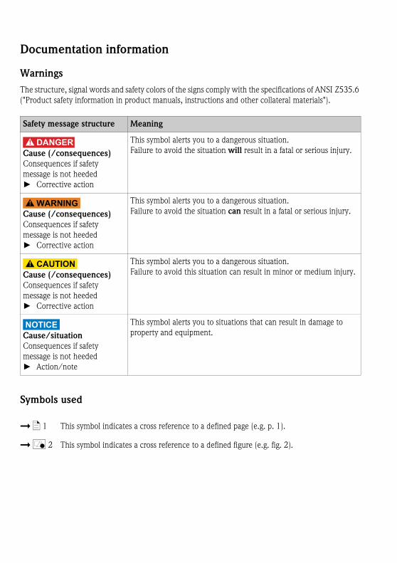
Warnings
The structure, signal words and safety colors of the signs comply with the specifications of ANSI Z535.6
("Product safety information in product manuals, instructions and other collateral materials").
Symbols used
Safety message structure Meaning
DANGER!
Cause (/consequences)
Consequences if safety
message is not heeded
► Corrective action
This symbol alerts you to a dangerous situation.
Failure to avoid the situation will result in a fatal or serious injury.
WARNING!
Cause (/consequences)
Consequences if safety
message is not heeded
► Corrective action
This symbol alerts you to a dangerous situation.
Failure to avoid the situation can result in a fatal or serious injury.
CAUTION!
Cause (/consequences)
Consequences if safety
message is not heeded
► Corrective action
This symbol alerts you to a dangerous situation.
Failure to avoid this situation can result in minor or medium injury.
NOTICECause/situation
Consequences if safety
message is not heeded
► Action/note
This symbol alerts you to situations that can result in damage to
property and equipment.
È ä 1 This symbol indicates a cross reference to a defined page (e.g. p. 1).
È å 2 This symbol indicates a cross reference to a defined figure (e.g. fig. 2).

Endress+Hauser
Indumax CLS50/CLS50D
Table of contents
1 Basic safety instructions . . . . . . 4
1.1 Requirements for personnel . . . . . . . . . . . . 4
1.2 Designated use . . . . . . . . . . . . . . . . . . . . . . 4
1.3 Occupational safety . . . . . . . . . . . . . . . . . . 4
1.4 Operational safety . . . . . . . . . . . . . . . . . . . 5
1.5 Product safety . . . . . . . . . . . . . . . . . . . . . . 5
2 Identification . . . . . . . . . . . . . . 7
2.1 Type code for versions with Ex approval . . . 7
2.2 Nameplate . . . . . . . . . . . . . . . . . . . . . . . . . 7
2.3 Temperature classes for hazardous locations 8
2.4 Certificates and approvals . . . . . . . . . . . . . . 8
3 Installation . . . . . . . . . . . . . . . . 9
3.1 Installation conditions . . . . . . . . . . . . . . . . 9
3.2 Installation . . . . . . . . . . . . . . . . . . . . . . . . 11
3.3 Post-installation check . . . . . . . . . . . . . . . 13
4 Wiring . . . . . . . . . . . . . . . . . . 14
4.1 Connection to the transmitter . . . . . . . . . 14
4.2 Wiring diagram for explosion-hazardous areas
15
5 Commissioning. . . . . . . . . . . . 18
6 Maintenance. . . . . . . . . . . . . . 18
7 Spare parts and return . . . . . . 19
7.1 Spare parts . . . . . . . . . . . . . . . . . . . . . . . . 19
7.2 Return . . . . . . . . . . . . . . . . . . . . . . . . . . . 20
8 Technical data . . . . . . . . . . . . 21
8.1 Input . . . . . . . . . . . . . . . . . . . . . . . . . . . . 21
8.2 Performance characteristics . . . . . . . . . . . 21
8.3 Environment . . . . . . . . . . . . . . . . . . . . . . 22
8.4 Process . . . . . . . . . . . . . . . . . . . . . . . . . . 22
8.5 Mechanical construction . . . . . . . . . . . . . 24
9 Appendix . . . . . . . . . . . . . . . . 25
9.1 Declaration of conformity for CLS50-G and
CLS50D-BA . . . . . . . . . . . . . . . . . . . . . . . 25
9.2 Declaration of conformity for CLS50-V . . . 27
Basic safety instructions Indumax CLS50/CLS50D
4 Endress+Hauser
1 Basic safety instructions
1.1 Requirements for personnel
► Installation, commissioning, operation and maintenance of the measuring system must only be
carried out by trained technical personnel.
► The technical personnel must be authorized by the plant operator to carry out the specified
activities.
► The electrical connection may only be performed by an electrical technician.
► The technical personnel must have read and understood these Operating Instructions and must
follow the instructions they contain.
► Measuring point faults may only be rectified by authorized and specially trained personnel.
Repairs not described in the enclosed Operating Instructions may only be carried out directly at
the manufacturer's or by the service organization.
1.2 Designated use
Indumax CLS50/CLS50D conductivity sensors are especially suitable for application in the chemical
industry and process engineering. The six-decade measuring range and the high chemical resistance of
the materials in contact with medium (PFA or PEEK) permit to use this sensor in a number of various
applications, e.g.:
• Concentration measurement of acids and bases
• Quality monitoring of chemical products in tanks and pipes
• Phase separation of product/product mixtures
Digital CLS50D sensors are used with Liquiline CM44x or Liquiline CM42. Analog CLS50 sensors are
used with the transmitters Liquiline CM42, Liquisys CLM223/253 or Mycom CLM153.
Any other use than the one described here compromises the safety of persons and the entire measuring
system and is not permitted.
The manufacturer is not liable for damage caused by improper or non-designated use.
NOTICEUse in not specified applications
Measurement errors and failures up to the breakdown of the measurement point possible
► Only use the product acc. to it’s specification.
► Note the technical data of the nameplate.
1.3 Occupational safety
As the user, you are responsible for complying with the following safety conditions:
• Guidelines for explosion protection
• Installation instructions
• Local prevailing standards and regulations.

Indumax CLS50/CLS50D Basic safety instructions
Endress+Hauser 5
1.4 Operational safety
► Before commissioning the entire measuring point, make sure all the connections are correct. Ensure
that electrical cables and hose connections are not damaged.
► Do not operate damaged products, and safeguard them to ensure that they are not operated
inadvertently. Mark the damaged product as defective.
► If faults cannot be rectified, the products must be taken out of service and secured against
unintentional commissioning.
1.5 Product safety
1.5.1 State of the art
The sensor has been designed and tested according to the state of the art and left the factory in perfect
functioning order.
Relevant regulations and European standards have been met.
1.5.2 Safety instructions for electrical equipment in hazardous locations
Sensors with ATEX approval (CLS50-G and CLS50D-BA for Zone 0 and CLS50-V for Zone 2) have been
developed and manufactured in compliance with applicable European standards and guidelines and are
suitable for use in hazardous locations. The Declaration of Conformity confirms compliance with the
harmonized European standards for using the sensors in hazardous locations.
CLS50-G and CLS50D-BA
• The sensors may be operated in Zone 0 (1G) classified locations.
• The sensors may be operated in liquid media providing a conductivity of >10 nS/cm, only.
• The measurement cable must be protected from electrostatic charging when applied in Ex-Zone 0
(1G).
CLS50-G
• The sensor may only be connected to the following transmitters:
– Mycom type CLM152-Z with transmitter module type FCL1, EC type-examination certificate
DMT 99 ATEX E 076
– Mycom type CLM153-G, EC type-examination certificate DMT 01 ATEX E 174
– Liquiline type CM42-IG, EC type-examination certificate EX5 05 03 30266 012
• The maximum permitted length of the measuring cable is 55 m (180 ft).
Basic safety instructions Indumax CLS50/CLS50D
6 Endress+Hauser
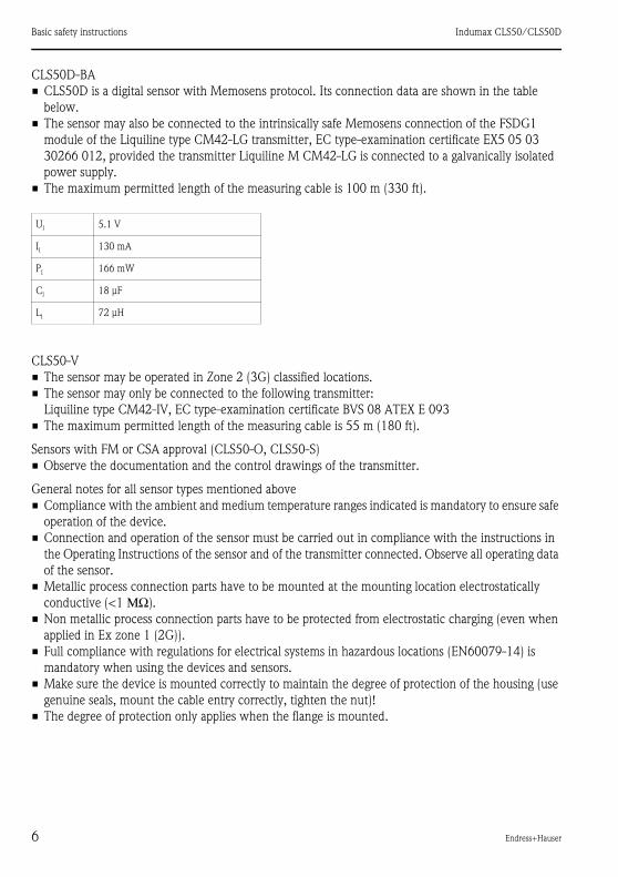
CLS50D-BA
• CLS50D is a digital sensor with Memosens protocol. Its connection data are shown in the table
below.
• The sensor may also be connected to the intrinsically safe Memosens connection of the FSDG1
module of the Liquiline type CM42-LG transmitter, EC type-examination certificate EX5 05 03
30266 012, provided the transmitter Liquiline M CM42-LG is connected to a galvanically isolated
power supply.
• The maximum permitted length of the measuring cable is 100 m (330 ft).
CLS50-V
• The sensor may be operated in Zone 2 (3G) classified locations.
• The sensor may only be connected to the following transmitter:
Liquiline type CM42-IV, EC type-examination certificate BVS 08 ATEX E 093
• The maximum permitted length of the measuring cable is 55 m (180 ft).
Sensors with FM or CSA approval (CLS50-O, CLS50-S)
• Observe the documentation and the control drawings of the transmitter.
General notes for all sensor types mentioned above
• Compliance with the ambient and medium temperature ranges indicated is mandatory to ensure safe
operation of the device.
• Connection and operation of the sensor must be carried out in compliance with the instructions in
the Operating Instructions of the sensor and of the transmitter connected. Observe all operating data
of the sensor.
• Metallic process connection parts have to be mounted at the mounting location electrostatically
conductive (<1 ΜΩ).
• Non metallic process connection parts have to be protected from electrostatic charging (even when
applied in Ex zone 1 (2G)).
• Full compliance with regulations for electrical systems in hazardous locations (EN60079-14) is
mandatory when using the devices and sensors.
• Make sure the device is mounted correctly to maintain the degree of protection of the housing (use
genuine seals, mount the cable entry correctly, tighten the nut)!
• The degree of protection only applies when the flange is mounted.
Ui 5.1 V
Ii 130 mA
Pi 166 mW
Ci 18 μF
Li 72 μH

Indumax CLS50/CLS50D Identification
Endress+Hauser 7
2 Identification
2.1 Type code for versions with Ex approval
2.2 Nameplate
The nameplate can be found on the sensor.
The following information is provided on the nameplate:
• Order code
• Extended order code
• Serial number
• Cell constant (nominal value)
• Protection class
• Pressure specification at 20 ˚C
• Continuous service temperature
Compare the data on the nameplate with your order.
To find out what CLS50D version you have, enter the order code indicated on the nameplate in
the search screen at the following address: www.products.endress.com/order-ident
Name Type Version
Indumax CLS50 - G x x x
for the use in hazardous locations,
ATEX II 1G Ex ia IIC T4/T6 Ga
Process connections, material
no Ex relevance
Name Type Version
Indumax CLS50 - V x x x
for the use in hazardous location,
ATEX II 3G Ex nL IIC T4/T6 Gc
Process connections, material
no Ex relevance
Name Type Version
Indumax CLS50D - BA x x x x - x x
for the use in hazardous location,
ATEX II 1G Ex ia IIC T4/T6 Ga
Process connections, material, cable connection,
calibration, service
no Ex relevance
Identification Indumax CLS50/CLS50D
8 Endress+Hauser
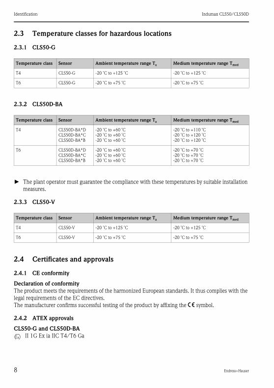
2.3 Temperature classes for hazardous locations
2.3.1 CLS50-G
2.3.2 CLS50D-BA
► The plant operator must guarantee the compliance with these temperatures by suitable installation
measures.
2.3.3 CLS50-V
2.4 Certificates and approvals
2.4.1 CE conformity
Declaration of conformity
The product meets the requirements of the harmonized European standards. It thus complies with the
legal requirements of the EC directives.
The manufacturer confirms successful testing of the product by affixing the 4 symbol.
2.4.2 ATEX approvals
CLS50-G and CLS50D-BA
II 1G Ex ia IIC T4/T6 Ga
Temperature class Sensor Ambient temperature range Ta Medium temperature range Tmed
T4 CLS50-G -20 ˚C to +125 ˚C -20 ˚C to +125 ˚C
T6 CLS50-G -20 ˚C to +75 ˚C -20 ˚C to +75 ˚C
Temperature class Sensor Ambient temperature range Ta Medium temperature range Tmed
T4 CLS50D-BA*D
CLS50D-BA*C
CLS50D-BA*B
-20 ˚C to +60 ˚C
-20 ˚C to +60 ˚C
-20 ˚C to +60 ˚C
-20 ˚C to +110 ˚C
-20 ˚C to +120 ˚C
-20 ˚C to +120 ˚C
T6 CLS50D-BA*D
CLS50D-BA*C
CLS50D-BA*B
-20 ˚C to +60 ˚C
-20 ˚C to +60 ˚C
-20 ˚C to +60 ˚C
-20 ˚C to +70 ˚C
-20 ˚C to +70 ˚C
-20 ˚C to +70 ˚C
Temperature class Sensor Ambient temperature range Ta Medium temperature range Tmed
T4 CLS50-V -20 ˚C to +125 ˚C -20 ˚C to +125 ˚C
T6 CLS50-V -20 ˚C to +75 ˚C -20 ˚C to +75 ˚C
Indumax CLS50/CLS50D Installation
Endress+Hauser 9
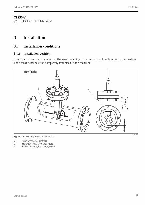
CLS50-V
II 3G Ex nL IIC T4/T6 Gc
3 Installation
3.1 Installation conditions
3.1.1 Installation position
Install the sensor in such a way that the sensor opening is oriented in the flow direction of the medium.
The sensor head must be completely immersed in the medium.
a0007035
Fig. 1: Installation position of the sensor
1 Flow direction of medium2 Minimum water level in the pipea Sensor distance from the pipe wall

Installation Indumax CLS50/CLS50D
10 Endress+Hauser
3.1.2 Installation factor
In narrow installation conditions, the conductivity measurement is affected by the pipe walls. This effect
is compensated by the so-called installation factor. The transmitter corrects the cell constant by
multiplication with the installation factor.
The value of the installation factor depends on the diameter and the conductivity of the pipe as well as
the sensor’s distance from the wall.
If the distance from the wall is sufficient (a > 15 mm (0.59"), from DN 80), it is not necessary to
consider the installation factor (f = 1.00).
If the distance from the wall is smaller, the installation factor increases in case of electrically insulating
pipes (f > 1) and decreases in case of electrically conductive pipes (f < 1).
The installation factor can be measured using calibration solutions or it can be approximately
determined from the following diagram.
a0005441
Fig. 2: Relationship between installation factor f and distance from wall a
1 Electrically conductive pipe wall2 Insulating pipe wall
3.1.3 Air set
CLS50
To compensate residual coupling in the cable and between the two sensor coils, you must perform a
zero calibration in air ("air set") before installing the sensor.
For further information, refer to the Operating Instructions of your transmitter.
CLS50D
The digital sensor is already adjusted at the factory, an on-side compensation is not necessary.
1
2
a [inch]
0 5 10 15 20 2525 a [mm]
0.80
1.00
1.20
1.40
f
0.20 0.39 0.59 0.79 0.98

Indumax CLS50/CLS50D Installation
Endress+Hauser 11
3.2 Installation
3.2.1 Flange installation
The sensor is suitable for installation in T-pieces ≥ DN 80 with the outgoing diameter reduced to
≥ DN 50.
WARNING!
Leakages
Danger of injuries by leaking medium
► Tighten the nut with a torque of 20 Nm.
► To avoid leakages, regularly check the tightness of the nut.
3.2.2 Flange, not in contact with medium
a0007062
Fig. 3: Fixed flange, in contact with medium (order option "process connection": 3, 4)12
Flange (stainless steel)Nut
34
O-ringSensor

Installation Indumax CLS50/CLS50D
12 Endress+Hauser
3.2.3 Flange, not in contact with medium
3.2.4 Lap-joint flange, not in contact with medium
a0007061
Fig. 4: Fixed flange, not in contact with medium (order option "process connection": 5, 6, 7)123
Flange (stainless steel)NutSealing disk (GYLON)
45
O-ringSensor
a0007063
Fig. 5: Lap-joint flange, not in contact with medium (order option "process connection": A, B, C)123
Lap-joint flange (PP-GF)Nut (stainless steel)Flange (PVDF)
45
O-ringSensor

Indumax CLS50/CLS50D Installation
Endress+Hauser 13
3.2.5 Assembly installation
3.3 Post-installation check
► Are sensor and cable undamaged?
► Is the installation position correct? Arrow on the threaded sleeve shows the flow direction =
installation position.
► Is the sensor installed via process connection and not suspended from the cable?
a0007064
Fig. 6: Installation of sensor with assembly12
CLA111 with suspension bracketCLA111 with flange connection
34
CLA140 with flange connectionCYA611

Wiring Indumax CLS50/CLS50D
14 Endress+Hauser
4 Wiring
WARNING!
Device is energized
Improper connection can cause injury or death.
► The electrical connection must only be carried out by a certified electrician.
► Technical personnel must have read and understood the instructions in this manual and must
adhere to them.
► Prior to beginning any wiring work, make sure voltage is not applied to any of the cables.
4.1 Connection to the transmitter
The sensor is supplied with a fixed cable. The connection to the transmitter can be extended using the
CYK11 (CLS50D) or the CLK6 (CLS50) special measuring cable (not applicable for use in hazardous
locations).
Please note that the residual coupling increases when the cable is extended.
a0017984
Fig. 7: CYK11 for cable extension for CLS50D–max. total cable length: 100 m (330 ft)
a0012998
Fig. 8: CLK6 for cable extension for CLS50–max. total cable length: 55 m (180 ft)
WH
RD
Pt100
YE
GN
RD
WH
BU
BN n.c.
RD
BU
Indumax CLS50/CLS50D Wiring
Endress+Hauser 15
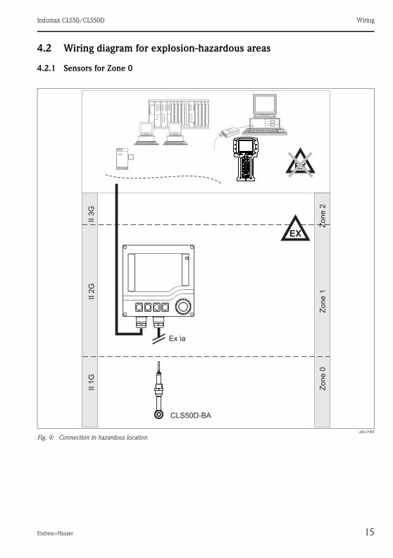
4.2 Wiring diagram for explosion-hazardous areas
4.2.1 Sensors for Zone 0
a0017985
Fig. 9: Connection in hazardous location

Wiring Indumax CLS50/CLS50D
16 Endress+Hauser
a0013258
Fig. 10: Connection in hazardous location
Indumax CLS50/CLS50D Wiring
Endress+Hauser 17
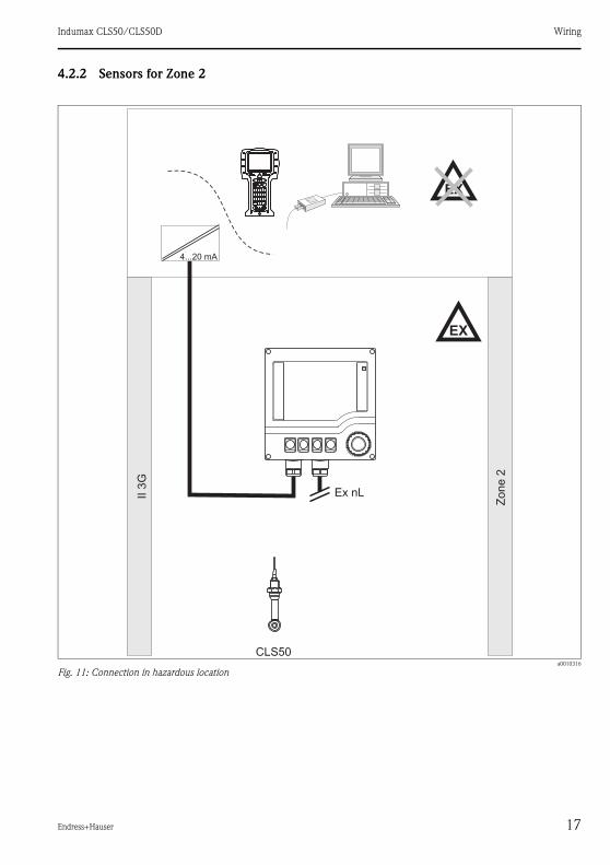
4.2.2 Sensors for Zone 2
a0010316
Fig. 11: Connection in hazardous location
EX
EX
Ex nL
CLS50
4...20 mA
II3
G
Zo
ne
2

Commissioning Indumax CLS50/CLS50D
18 Endress+Hauser
5 Commissioning
Before first commissioning, check if:
• the sensor is correctly installed
• the electrical connection is correct.
If using an assembly with automatic cleaning, check the correct connection of the cleaning agent (e.g.
water or air).
WARNING!
Incorrect connection of a cleaning unit to an assembly
Danger of medium leaking off
► Before applying compressed air to an assembly with cleaning facility, make sure the connections are
correctly fitted. Otherwise, the assembly may not be inserted into the process.
6 Maintenance
WARNING!
Burning chemicals
Danger of chemicals burns to the eyes and skin. Danger of damage to clothing and equipment.
► It is absolutely essential to protect the eyes and hands properly when working with acids, bases and
organic solvents!
► Wear protective goggles and safety gloves.
► Clean away splashes on clothes and other objects to prevent any damage.
► Pay particular attention to the information provided in the safety data sheets for the chemicals used.
Clean away fouling on the sensor as follows depending on the particular type of fouling:
• Oily and greasy films:
Clean with grease remover, e.g. alcohol, acetone, as well as hot water and dishwashing detergent if
necessary.
• Lime and metal hydroxide buildup:
Dissolve buildup with diluted hydrochloric acid (3 %) and then rinse thoroughly with plenty of clear
water.
• Sulfidic buildup (from flue gas desulfurising or sewage treatment plants):
Use a mixture of hydrochloric acid (3 %) and thiocarbamide (commercially available) and then rinse
thoroughly with plenty of clear water.
• Buildup containing proteins (e.g. food industry):
Use a mixture of hydrochloric acid (0.5 %) and pepsin (commercially available) and then rinse
thoroughly with plenty of clear water.
Indumax CLS50/CLS50D Spare parts and return
Endress+Hauser 19
7 Spare parts and return
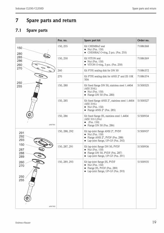
7.1 Spare parts
Pos. no. Spare part kit Order no.
a0007081
150, 255 Kit CHEMRAZ seal
• Nut (Pos. 150)
• CHEMRAZ O-ring, 2 pcs. (Pos. 255)
71086368
150, 250 Kit VITON seal
• Nut (Pos. 150)
• VITON O-ring, 3 pcs. (Pos. 250)
71086369
260 Kit PTFE sealing disk for DN 50 71086372
270 Kit PTFE sealing disk for ANSI 2" and JIS 10K
50A
71086374
150, 280 Kit fixed flange DN 50, stainless steel 1.4404
(AISI 316L)
• Nut (Pos. 150)
• Flange DN 50 (Pos. 280)
51500525
150, 285 Kit fixed flange ANSI 2", stainless steel 1.4404
(AISI 316L)
• Nut (Pos. 150)
• Flange ANSI 2" (Pos. 285)
51500527
150, 286 Kit fixed flange JIS, stainless steel 1.4404
(AISI 316 L)Nut
• (Pos. 150)
• Flange DN 50 (Pos. 286)
51500934
a0007082
150, 288, 292 Kit lap-joint flange ANSI 2", PVDF
• Nut (Pos. 150)
• Flange ANSI 2", PVDF (Pos. 288)
• Lap-joint flange, UP-GF (Pos. 292)
51500937
150, 287, 291 Kit lap-joint flange DN 50, PVDF
• Nut (Pos. 150)
• Flange DN 50, PVDF (Pos. 287)
• Lap-joint flange, UP-GF (Pos. 291)
51500936
150, 289, 293 Kit lap-joint flange JIS, PVDF
• Nut (Pos. 150)
• Flange JIS, PVDF (Pos. 289)
• Lap-joint flange, UP-GF (Pos. 293)
51500935
Spare parts and return Indumax CLS50/CLS50D
20 Endress+Hauser
7.2 Return
The device must be returned if repairs or a factory calibration are required, or if the wrong device has
been ordered or delivered. According to legal regulations, Endress+Hauser, as an ISO-certified
company, is required to follow certain procedures when handling returned products that are in contact
with medium.
To ensure swift, safe and professional device returns, please read the return procedures and conditions
on the internet site:
www.services.endress.com/return-material
Indumax CLS50/CLS50D Technical data
Endress+Hauser 21
8 Technical data
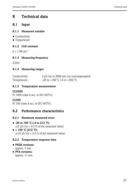
8.1 Input
8.1.1 Measured variable
• Conductivity
• Temperature
8.1.2 Cell constant
k = 1.98 cm–1
8.1.3 Measuring frequency
2 kHz
8.1.4 Measuring ranges
8.1.5 Temperature measurement
CLS50D
Pt 1000 (class A acc. to IEC 60751)
CLS50
Pt 100 (class A acc. to IEC 60751)
8.2 Performance characteristics
8.2.1 Maximum measured error
• -20 to 100 ˚C (-4 to 212 ˚F):
±(5 μS/cm + 0.5 % of the measured value)
• > 100 ˚C (212 ˚F):
±(10 μS/cm + 0.5 % of the measured value)
8.2.2 Temperature response time
• PEEK versions:
approx. 7 min
• PFA versions:
approx. 11 min
Conductivity: 2 μS/cm to 2000 mS/cm (uncompensated)
Temperature: –20 to +180 ˚C (-4 to +350 ˚F)
Technical data Indumax CLS50/CLS50D
22 Endress+Hauser
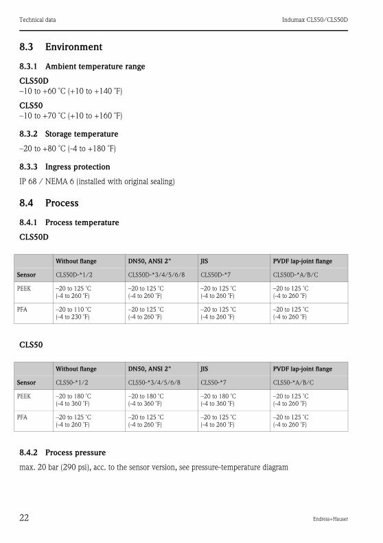
8.3 Environment
8.3.1 Ambient temperature range
CLS50D
–10 to +60 ˚C (+10 to +140 ˚F)
CLS50
–10 to +70 ˚C (+10 to +160 ˚F)
8.3.2 Storage temperature
–20 to +80 ˚C (-4 to +180 ˚F)
8.3.3 Ingress protection
IP 68 / NEMA 6 (installed with original sealing)
8.4 Process
8.4.1 Process temperature
CLS50D
CLS50
8.4.2 Process pressure
max. 20 bar (290 psi), acc. to the sensor version, see pressure-temperature diagram
Without flange DN50, ANSI 2" JIS PVDF lap-joint flange
Sensor CLS50D-*1/2 CLS50D-*3/4/5/6/8 CLS50D-*7 CLS50D-*A/B/C
PEEK –20 to 125 ˚C
(-4 to 260 ˚F)
–20 to 125 ˚C
(-4 to 260 ˚F)
–20 to 125 ˚C
(-4 to 260 ˚F)
–20 to 125 ˚C
(-4 to 260 ˚F)
PFA –20 to 110 ˚C
(-4 to 230 ˚F)
–20 to 125 ˚C
(-4 to 260 ˚F)
–20 to 125 ˚C
(-4 to 260 ˚F)
–20 to 125 ˚C
(-4 to 260 ˚F)
Without flange DN50, ANSI 2" JIS PVDF lap-joint flange
Sensor CLS50-*1/2 CLS50-*3/4/5/6/8 CLS50-*7 CLS50-*A/B/C
PEEK –20 to 180 ˚C
(-4 to 360 ˚F)
–20 to 180 ˚C
(-4 to 360 ˚F)
–20 to 180 ˚C
(-4 to 360 ˚F)
–20 to 125 ˚C
(-4 to 260 ˚F)
PFA –20 to 125 ˚C
(-4 to 260 ˚F)
–20 to 125 ˚C
(-4 to 260 ˚F)
–20 to 125 ˚C
(-4 to 260 ˚F)
–20 to 125 ˚C
(-4 to 260 ˚F)

Indumax CLS50/CLS50D Technical data
Endress+Hauser 23
8.4.3 Pressure-temperature diagram
a0018311
Fig. 12: Pressure-temperature-diagram of CLS50D
1 PEEK sensor, without flange2 PFA sensor, without flange (blue line)3 PEEK or PFA sensor, with DN50/ANSI 2" flange (red line)4 PEEK or PFA sensor, with JIS flange5 PEEK or PFA sensor, with lap-joint flange PVDF (green line)
a0018312
Fig. 13: Pressure-temperature-diagram of CLS50
1 PEEK sensor, without flange2 PFA sensor, without flange or with DN50/ANSI 2" flange (blue line)3 PEEK sensor, with DN50/ANSI 2" flange (red line)4 PFA sensor, with JIS flange (black line)5 PEEK or PFA sensor, with lap-joint flange PVDF (green line)6 PEEK sensor, with JIS flange (grey line)
Technical data Indumax CLS50/CLS50D
24 Endress+Hauser
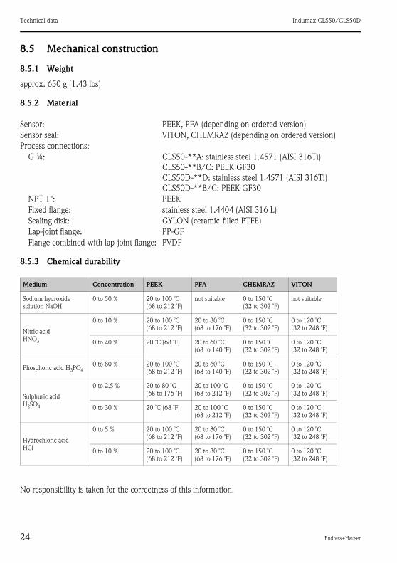
8.5 Mechanical construction
8.5.1 Weight
approx. 650 g (1.43 lbs)
8.5.2 Material
8.5.3 Chemical durability
No responsibility is taken for the correctness of this information.
Sensor: PEEK, PFA (depending on ordered version)
Sensor seal: VITON, CHEMRAZ (depending on ordered version)
Process connections:
G ¾: CLS50-**A: stainless steel 1.4571 (AISI 316Ti)
CLS50-**B/C: PEEK GF30
CLS50D-**D: stainless steel 1.4571 (AISI 316Ti)
CLS50D-**B/C: PEEK GF30
NPT 1": PEEK
Fixed flange: stainless steel 1.4404 (AISI 316 L)
Sealing disk: GYLON (ceramic-filled PTFE)
Lap-joint flange: PP-GF
Flange combined with lap-joint flange: PVDF
Medium Concentration PEEK PFA CHEMRAZ VITON
Sodium hydroxide
solution NaOH
0 to 50 % 20 to 100 ˚C
(68 to 212 ˚F)
not suitable 0 to 150 ˚C
(32 to 302 ˚F)
not suitable
Nitric acid
HNO3
0 to 10 % 20 to 100 ˚C
(68 to 212 ˚F)
20 to 80 ˚C
(68 to 176 ˚F)
0 to 150 ˚C
(32 to 302 ˚F)
0 to 120 ˚C
(32 to 248 ˚F)
0 to 40 % 20 ˚C (68 ˚F) 20 to 60 ˚C
(68 to 140 ˚F)
0 to 150 ˚C
(32 to 302 ˚F)
0 to 120 ˚C
(32 to 248 ˚F)
Phosphoric acid H3PO4
0 to 80 % 20 to 100 ˚C
(68 to 212 ˚F)
20 to 60 ˚C
(68 to 140 ˚F)
0 to 150 ˚C
(32 to 302 ˚F)
0 to 120 ˚C
(32 to 248 ˚F)
Sulphuric acid
H2SO4
0 to 2.5 % 20 to 80 ˚C
(68 to 176 ˚F)
20 to 100 ˚C
(68 to 212 ˚F)
0 to 150 ˚C
(32 to 302 ˚F)
0 to 120 ˚C
(32 to 248 ˚F)
0 to 30 % 20 ˚C (68 ˚F) 20 to 100 ˚C
(68 to 212 ˚F)
0 to 150 ˚C
(32 to 302 ˚F)
0 to 120 ˚C
(32 to 248 ˚F)
Hydrochloric acid
HCl
0 to 5 % 20 to 100 ˚C
(68 to 212 ˚F)
20 to 80 ˚C
(68 to 176 ˚F)
0 to 150 ˚C
(32 to 302 ˚F)
0 to 120 ˚C
(32 to 248 ˚F)
0 to 10 % 20 to 100 ˚C
(68 to 212 ˚F)
20 to 80 ˚C
(68 to 176 ˚F)
0 to 150 ˚C
(32 to 302 ˚F)
0 to 120 ˚C
(32 to 248 ˚F)
Indumax CLS50/CLS50D Appendix
Endress+Hauser 25
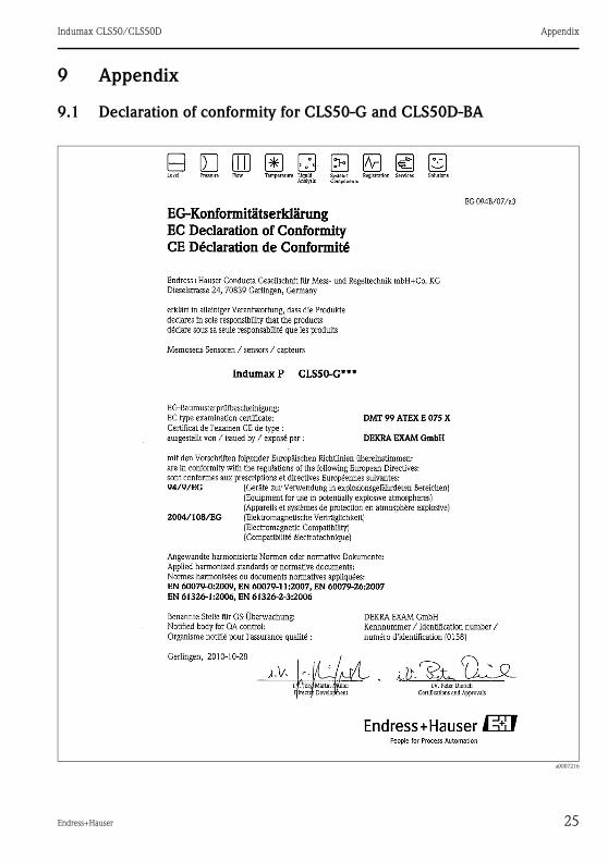
9 Appendix
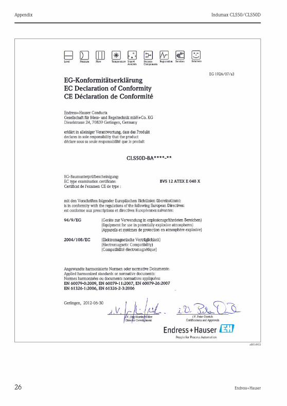
9.1 Declaration of conformity for CLS50-G and CLS50D-BA
a0007216
Appendix Indumax CLS50/CLS50D
26 Endress+Hauser
a0014933
Indumax CLS50/CLS50D Appendix
Endress+Hauser 27
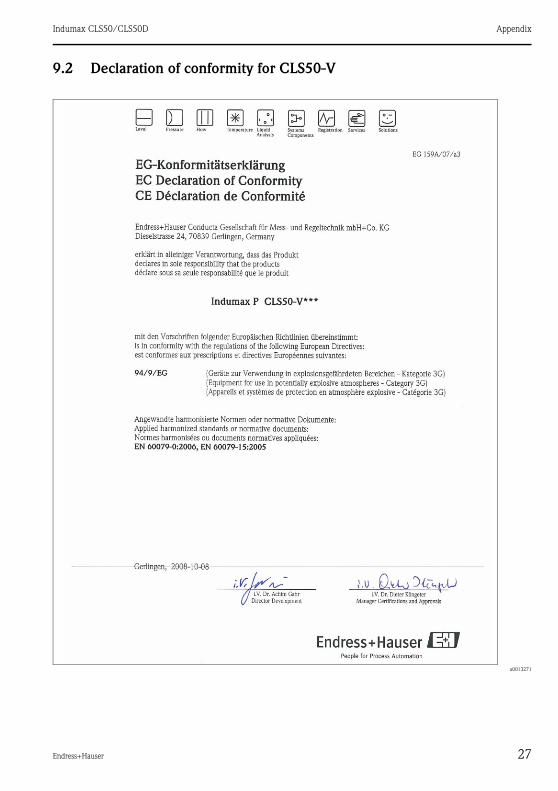
9.2 Declaration of conformity for CLS50-V
a0013271

BA00182C/07/EN/15.12
FM9 / DT