operating instructions for elcometer 456...operating instructions for elcometer 456 basic models...
TRANSCRIPT

Operating Instructionsfor
Elcometer 456
Basic Models
Ferrous, Non-Ferrousand
Dual Ferrous/Non-FerrousModels
(F, N & FNF)
FNF UK Patent No: 2306009BFNF US Patent No: 5886522

This product meets the emc directive89/336/EEC, amended 92/31/EEC & 93/68/EEC
WarningThis instrument uses a Liquid Crystal Display. If it isheated above 50˚C (120˚F) it may be damaged. Thiscan happen if it is left in a car parked in strong sunlight.
, and are registeredtrademarks of Elcometer Instruments Ltd.
©Elcometer Instruments Ltd. England 2000/2001
All rights reserved. No part of this document may bereproduced, transmitted, transcribed, stored (in aretrieval system or otherwise) or translated into anylanguage in any form or by any means (electronic,mechanical, magnetic, optical, manual or otherwise)without the prior written permission of ElcometerInstruments Ltd.
Doc.No: TMA-0239 Issue 01Text with cover Part No: 16454
®
Elcometer 456Basic Models
ContentsPage No.
1 Introduction 1
2 Getting Started 3
3 MENU STRUCTURE 7
4 General Operating Instructions 12
5 Calibration Adjustment 16
6 Data Output 21
7 Service 22
8 Error Messages 23
9 Technical Data 24
10 Accessories 31
11 Glossary 33

1
1 INTRODUCTIONThe Elcometer 456 Coating Thickness Gauges have afull range of probe options for ferrous (F), non-ferrous(N) and dual ferrous/non-ferrous (FNF) operation.
The F probes measure the thickness of non-magneticcoatings on steel or iron substrates. They can be usedon paint, plastic, galvanising, enamel, powder, hardchrome and other coatings such as electroless nickel.
The N probes are for measuring the thickness of non-magnetic coatings on non-magnetic metals. They canbe used on anodising, paint, plastic coatings, powder,etc applied to aluminium, brass, non-magneticstainless steel, etc.
The FNF probes are dual function with Automatic orManual substrate selection.
The gauges are available as either integral probe orseparate probe versions. All separate probes are fullyinterchangeable and there is a Plug IN Integral Probe(PINIP™) option so that an integral style probe can bepluged in to a separate probe type gauge.
Coatings on Galvanised or Metallised (Al andZn) Steel Using the FNFThe FNF in fixed N mode may be used to measurepaint coatings on galvanised, aluminium or zincsprayed steel substrates. The instrument must be setto the manual mode before the N mode is selected.The unit should then be zeroed and calibrated on asample of the coated steel. Care must be taken toensure that the calibration conditions are not affectedby changes in the zinc or aluminium coating thickness.This can be determined by checking the zero over anarea of the galvanised or metal-coated steel. Metalcoatings on steel above 50µm (2 mil/thou) should beconsistent enough to obtain a stable zero on the layerof metal.
2
1.1 FeaturesThe Elcometer 456 Basic versions have a graphicsdisplay, multiple calibration adjustment options,backlight and infrared data output.
For readings memory see the Standard and Topversions.
1.2 The Package contains
456 Gauge
456 Probe (Chosen from the list of options,including integral probes.)
Calibration Foils
Carrying Pouch
Batteries
Operating Instruction Book
3
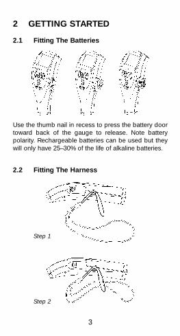
2 GETTING STARTED
2.1 Fitting The Batteries
Use the thumb nail in recess to press the battery doortoward back of the gauge to release. Note batterypolarity. Rechargeable batteries can be used but theywill only have 25–30% of the life of alkaline batteries.
2.2 Fitting The Harness
Step 1
Step 2

4
2.3 Fitting The Separate Probes
Align connector keyway andpush home. The connectorlocks automatically.NOTE: The design of theprobe connector allowssome movement between theprobe and the gauge. This isintentional and does notaffect measurementperformance.
To release the probe, graspthe knurled section and pullgently away from the gauge.The connection will unlockand the probe will release.
Step 3
5
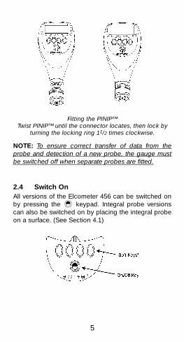
Fitting the PINIP™Twist PINIP™ until the connector locates, then lock by
turning the locking ring 11/2 times clockwise.
NOTE: To ensure correct transfer of data from theprobe and detection of a new probe, the gauge mustbe switched off when separate probes are fitted.
2.4 Switch OnAll versions of the Elcometer 456 can be switched onby pressing the keypad. Integral probe versionscan also be switched on by placing the integral probeon a surface. (See Section 4.1)

6
2.4.1 Soft Keys
Softkey operations depend on the screen beingviewed and are indicated on the screen as in theexample above.
Some screens allow the status of a feature to bechanged e.g. on to off or select or deselect, etc. A tickbox indicates this type of feature. Use the BACKsoftkey to close the screen without a change or use theSEL softkey to change the status, tick off to on or tickon to off. See Section 3.3 for an example.
To return from any screen to the Reading screen pressthe BACK softkey until the Reading screen appears.
2.5 Taking a Reading
or
456 Separate and Integral Probe beingplaced on surface.
CAL STATS MENU
F1
7
3 MENU STRUCTURE
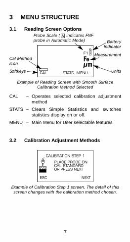
3.1 Reading Screen Options
Example of Reading Screen with Smooth SurfaceCalibration Method Selected
CAL – Operates selected calibration adjustmentmethod
STATS – Clears Simple Statistics and switchesstatistics display on or off.
MENU – Main Menu for User selectable features
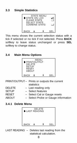
3.2 Calibration Adjustment Methods
Example of Calibration Step 1 screen. The detail of thisscreen changes with the calibration method chosen.
CALIBRATION STEP 1
PLACE PROBE ONCAL STANDARDOR PRESS NEXT
ESC NEXT
CAL STATS MENU
F1
BatteryIndicator
Measurement
Units
Cal MethodIcon
Softkeys
Probe Scale ( indicates FNFprobe in Automatic Mode)
A
8
3.3 Simple Statistics
This menu shows the current selection status with atick if selected or no tick if not selected. Press BACKsoftkey to leave status unchanged or press SELsoftkey to change status.
3.4 Main Menu Options
PRINT/OUTPUT – Prints or outputs the currentstatistics
DELETE – Last reading onlySETUP – Select featuresRESET – Select Cal or Gauge resetsABOUT – Select Probe or Gauge information
3.4.1 Delete Menu
LAST READING – Deletes last reading from thestatistical calculation.
DELETELAST READING
BACK SEL
MENUPRINT/OUTPUTDELETESETUPRESETABOUT
BACK SEL
STATS MENUSTATS ON LCDCLEAR STATSSELECT STATSCOMBINE STATS
BACK SEL

9
3.4.2 Setup Menu
CAL METHOD – Selects calibration method fromlist. See Section 5
STATISTICS – To select simple statistics to bedisplayed from list and combinestatistics for Dual probes.
BACKLIGHT – Switches feature on or off. Whenswitched on, the backlightilluminates the display for 4seconds after each reading or keypress. Use of the backlightreduces the battery life.
PROBE – Displays probe type in use andselects range on dual functionprobes, F1 2 or FNF1.
UNITS – Selects measurement units
OUTPUT – Select infrared printer output.
BEEP VOLUME – Switch bleep off or set level from 1(low) to 5 (high).
LANGUAGE – Select from list.*
AUTO – Select delay time or turn thisSWITCH-OFF feature off.
OPENING – Turn this feature on or off.SCREEN
SETUPCAL METHODSTATISTICSBACKLIGHTPROBEUNITSOUTPUT
BACK SEL
* See next page

10
3.4.3 Reset
FACTORY CAL – Returns gauge to calibrationadjustment set at time ofmanufacture.
INTL GAUGE – Resets the gauge to Internationaldefault settings eg. DD/MM/YYdate format and metric units.
US GAUGE – Resets the gauge to USA defaultsettings eg. MM/DD/YY dateformat and imperial units.
RESETFACTORY CALINTL GAUGEUSA GAUGE
BACK SEL
* To change language which is not understood:
Press left hand key until READING SCREEN isdisplayed.
Press right hand key once - displays MAIN MENU.
Press key (3rd from left) twice - moves cursor toSETUP selection.
Press right hand key once - displays SETUP MENU.
Press key (3rd from left) 8 times - moves cursor toLANGUAGE selection.
Press right hand key once - displays languageoptions.
Move cursor to recognised language, press righthand key to select.
➔➔
11
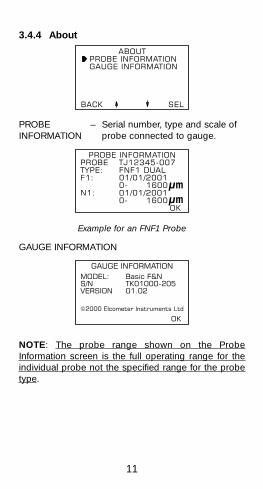
3.4.4 About
PROBE – Serial number, type and scale ofINFORMATION probe connected to gauge.
Example for an FNF1 Probe
GAUGE INFORMATION
NOTE: The probe range shown on the ProbeInformation screen is the full operating range for theindividual probe not the specified range for the probetype.
GAUGE INFORMATIONMODEL: Basic F&NS/N TK01000-205VERSION 01.02
©2000 Elcometer Instruments Ltd
OK
PROBE INFORMATIONPROBE TJ12345-007TYPE: FNF1 DUALF1: 01/01/2001
0- 1600N1: 01/01/2001
0- 1600OK
ABOUTPROBE INFORMATIONGAUGE INFORMATION
BACK SEL

12
4 GENERAL OPERATINGINSTRUCTIONS
4.1 Switch On/Switch OffGauges with Separate and PINIP probes are switchedon or off by pressing .
Integral probe units switch on when the probe isplaced on a surface.
To switch off all gauge types, press and hold for 3seconds. The gauge will bleep, two single tonesfollowed by a double tone.

13
The Elcometer 456 switches itself off 60 seconds afterthe last operation unless the Auto Switch Off time ischanged in the SETUP menu. The Auto Switch Offfeature can be set to a maximum of 10 minutes or canbe deactivated in the SETUP menu.
4.2 Opening Screen & Readings Screen
The opening screen can be deactivated in the SETUPmenu. The gauge then wakes up showing the readingscreen.
Reading Screen with all statistics activated.
NOTE: If CAL softkey indicator is flashing the gaugeshould be recalibrated. This is due to the calibrationadjustment method having been changed or a probechange. See Section 5.3
4.3 Select LanguageThe most suitable language for the user can beselected within the Setup menu under the Languageoption. See section 3.4.2.
CAL STATS MENU
F1
14
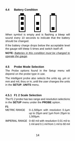
4.4 Battery Condition
When symbol is empty and is flashing a bleep willsound every 10 seconds to indicate that the batteryshould be changed.
If the battery charge drops below the acceptable levelthe gauge will bleep 5 times and switch itself off.
NOTE: Batteries in this condition must be changed tooperate the gauge.
4.5 Probe Mode SelectionThe Probe options found in the Setup menu willdepend on the probe type in use.
The intelligent probe also selects the units eg. µm ormm and mil, thou or in, until the user changes the unitsin the SETUP, UNITS menu.
4.5.1 F1 2 Scale SelectionThe F1 2 probe has two range and resolution selectionsin the SETUP menu under the PROBE option.
F1METRIC RANGE 0–1,500µm with resolution 0.1µm
up to 20µm and 1µm from 20µm to1,500µm.
IMPERIAL RANGE 0–60 mil with resolution 0.01 mil to1 mil and 0.1 mil from 1 mil to 60 mil
15
F2METRIC RANGE 0–5.00mm with resolution of 1µm
(0.001mm) to 1.00mm and 10µm(0.01mm) from 1.00mm to 5.00mm
IMPERIAL RANGE 0–200 mil with resolution of 0.1 to50 mil and 1.0 mil from 50 to 200 mil
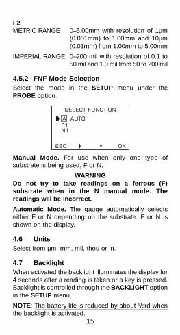
4.5.2 FNF Mode SelectionSelect the mode in the SETUP menu under thePROBE option.
Manual Mode. For use when only one type ofsubstrate is being used, F or N.
WARNINGDo not try to take readings on a ferrous (F)substrate when in the N manual mode. Thereadings will be incorrect.
Automatic Mode. The gauge automatically selectseither F or N depending on the substrate. F or N isshown on the display.
4.6 UnitsSelect from µm, mm, mil, thou or in.
4.7 BacklightWhen activated the backlight illuminates the display for4 seconds after a reading is taken or a key is pressed.Backlight is controlled through the BACKLIGHT optionin the SETUP menu.
NOTE: The battery life is reduced by about 1/3rd whenthe backlight is activated.
SELECT FUNCTION
AUTOF1N1
ESC OK
16
5 CALIBRATION ADJUSTMENT
5.1 Factory CalibrationThe gauge is dispatched from the factory with a pre-set(factory) calibration. This can be restored at any timethrough the RESET menu in SETUP.
The Elcometer 456 should be adjusted before use or atleast checked to ensure that it has been previouslyadjusted correctly for the conditions of use.
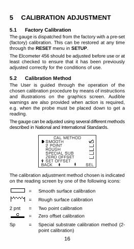
5.2 Calibration MethodThe User is guided through the operation of thechosen calibration procedure by means of instructionsand illustrations on the graphics screen. Audiblewarnings are also provided when action is required,e.g. when the probe must be placed down to get areading.
The gauge can be adjusted using several different methodsdescribed in National and International Standards.
The calibration adjustment method chosen is indicatedon the reading screen by one of the following icons:
= Smooth surface calibration
= Rough surface calibration
2 pnt = Two point calibration
= Zero offset calibration
Sp = Special substrate calibration method (2-point calibration)
CAL METHODSMOOTH2 POINTROUGHSPECIAL SUBZERO OFFSETSET OFFSET
BACK SEL

17
5.3 Calibration AdjustmentCalibration adjustment should be carried out with theappropriate probe on the same type of metal, the samecurvature and similar finish to the item to be measured.It is best to use an uncoated sample of the items to betested.
Calibration can be carried out using measured foils orcoated standards. The use of coated standards onlyconfirms that the gauge meets its specifications. Whenusing foils care must be taken to keep the foils cleanand free from dust and to avoid damage by creasingparticularly the lower value foils.
NOTE: To calibrate 5mm (200 mils) and 13mm (500mils) range gauges it will be necessary to stack thefoils. Care must also be taken to avoid errors due toplacing the foil labels between the foils.
SMOOTH – Smooth surface calibration where the gaugeis set to zero on the uncoated surface and a knownthickness above the expected thickness of the coating.
2-POINT – Calibration on a thin value and a thick valueeither side of the expected thickness. This will enhancethe accuracy of the gauge over the thickness rangedefined by the two values. This method is also calledRough Surface Calibration.
SPECIAL SUB – This method uses the 2-pointcalibration for unusual substrate materials such as castiron, certain types of stainless steel, high carbon steel,special aluminium alloys, etc.
18
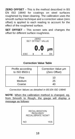
ZERO OFFSET – This is the method described in BSEN ISO 19840 for coatings on steel surfacesroughened by blast cleaning. The calibration uses thesmooth surface technique and a correction value (zerooffset) is applied to each reading to account for theeffect of the roughened surface.
SET OFFSET – This screen sets and changes theoffset for different surface roughness.
Correction Value Table
Correction Values as detailed in BS EN ISO 19840
NOTE: When the calibration method is changed, eg.from Smooth to Rough, the gauge will display amessage as follows:
RECALIBRATIONREQUIRED
RECALIBRATE NOW?
NO YES
ZEROSET OFFSET VALUE
0.0ESC OK
Profile according Correction Value µmto ISO 8503-1 (Zero Offset)
Fine 10Medium 25Coarse 40
19
If the "NO" key is pressed the CAL softkey indicator onthe Readings display will flash to warn that calibrationadjustment is still required.
If the "YES" key is pressed the calibration adjustmentroutine is activated.
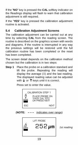
5.4 Calibration Adjustment ScreensThe calibration adjustment can be carried out at anytime by selecting CAL from the reading screen. Theroutine is described on the graphics screen with wordsand diagrams. If the routine is interrupted in any waythe previous settings will be restored until the fullcalibration routine has been completed or the resethas been completed.
The screen detail depends on the calibration methodchosen but the calibration is in two steps:
Step 1 Place the probe on a calibration standard andlift the probe. Repeating the reading willdisplay the average ( x̄ ) and the last reading.The displayed reading value can be adjustedwith or keys until it is correct.
Press set to enter the value.
(NOTE: – – – indicates over range)
LIFT PROBE
252
CALIBRATION STEP 1
PLACE PROBE ONTHICK CAL STDOR PRESS NEXT
ESC NEXT
➔
➔
1st reading

20
Step 2 Place the probe on an uncoated standard(smooth calibration) or a thin calibrationstandard (2-point, rough, special substrateetc.). Repeating the reading will display theaverage ( x̄ ) and the last reading. Thedisplayed reading can be adjusted with thesoftkeys.
Press SET to enter the value.
NOTE: Pressing NEXT will skip Step 1 or Step 2.Pressing ESC will return to the readings display withthe calibration unchanged.
REPLACE PROBE ONU-BASE OR PRESSZERO THEN SET
�: -0.9LAST RDG -0.7ESC ZERO SET
LIFT PROBE
-0.7
CALIBRATION STEP 2
PLACE PROBE ONUNCOATED BASEOR PRESS NEXT
ESC NEXT
REPLACE PROBE ONCAL STANDARD ORADJ - PRESS SET
�: 253LAST RDG 252ESC SET
1st reading
2nd andsubsequent
readings
2nd andsubsequent
readings
21
6 DATA OUTPUTA statistical summary can be output via the infraredinterface to a suitable printer.
The Elcometer 456 Basic version is fitted with anInfraRed printer output port and is programmed towork with the Hewlett Packard (HP) InfraRed PortablePrinter.
Other InfraRed printers with different print protocolsmay not be supported. Consult your local dealer.
The Elcometer 456 Basic sends the current statisticalsummary when operated from the MENU, PRINT/OUTPUT option.

22
7 SERVICEYou own probably the finest hand-held coatingthickness gauge in the world today. If looked after, itwill last a lifetime.
Regular calibration checks over the life of the gaugeand its probe are a requirement of quality managementprocedures, e.g. ISO 9000 and other quality standards.For gauge checks and certification contact your localElcometer dealer.
In the unlikely event of a fault the gauge should bereturned to your local Elcometer dealer, directly toElcometer Instruments Ltd. or contact us for advice at:
e-mail: [email protected] [email protected]
Web: www.elcometer.com
Tel: +44 (0)161 371 6000
Fax: +44 (0)161 371 6010
NOTE: Probes will eventually wear. Probe life willdepend on the number of measurements taken andhow abrasive the coating is. Replacement separateand PINIP probes can be fitted by the User without theneed to return the gauge for service.
Integral probe gauges have to be returned forreprogramming or replacement if worn or damaged.

23
8 ERROR MESSAGESUnder certain conditions the gauge will display errormessages. These messages are normally cleared bypressing any one of the softkeys. The error messagewill contain an indication of the cause which should becorrected before proceeding.
24
9 TECHNICAL DATAScale Ranges: Probe Options
The F1 2 scale combines the F1 scale with the F2 scalein a single probe with the user selecting theappropriate range for the work in hand. The resolutionof the gauge is dependent on the scale selected on thegauge.
Integral Probe Options
456F, 456N & 456FNF F1, F1 2, F3, N1 & FNF1Scales
Separate Probe Options
456F, 456N, & 456FNF (F1, F1 2, F3, N1, N1A &FNF1 Scales)
Right Angle Separate Probes are available for F1,F1 2, N1 and FNF1 Scales
A Telescopic Separate Probe is available for theF1 and F1 2 Scales.
An Anodiser’s Probe is available for the N1 Scale.
Integral Probe Options
PINIP Probes (Plug IN Integral Probe) areavailable in place of Separate probes with cablesfor F1, F1 2, F3, N1 and FNF1 Scales.
25
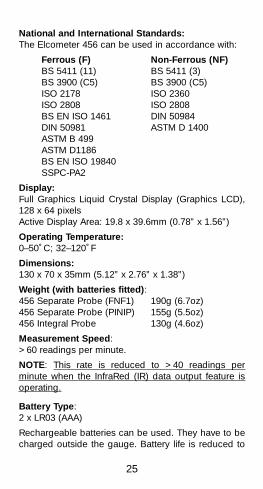
National and International Standards:The Elcometer 456 can be used in accordance with:
Ferrous (F) Non-Ferrous (NF)BS 5411 (11) BS 5411 (3)BS 3900 (C5) BS 3900 (C5)ISO 2178 ISO 2360ISO 2808 ISO 2808BS EN ISO 1461 DIN 50984DIN 50981 ASTM D 1400ASTM B 499ASTM D1186BS EN ISO 19840SSPC-PA2
Display:Full Graphics Liquid Crystal Display (Graphics LCD),128 x 64 pixelsActive Display Area: 19.8 x 39.6mm (0.78” x 1.56”)
Operating Temperature:0–50˚C; 32–120˚F
Dimensions:130 x 70 x 35mm (5.12” x 2.76” x 1.38”)
Weight (with batteries fitted):456 Separate Probe (FNF1) 190g (6.7oz)456 Separate Probe (PINIP) 155g (5.5oz)456 Integral Probe 130g (4.6oz)
Measurement Speed:>60 readings per minute.
NOTE: This rate is reduced to >40 readings perminute when the InfraRed (IR) data output feature isoperating.
Battery Type:2 x LR03 (AAA)
Rechargeable batteries can be used. They have to becharged outside the gauge. Battery life is reduced to

26
approximately 25% of the dry battery life when usingrechargeable batteries. Follow the batterymanufacturer’s instructions when charging anddisposing of rechargeable batteries.
Do not dispose of in fire.
Battery Life:30–40 hours continuous use with alkaline dry batteries.(15,000–20,000 readings at an average of 8 readingsper minute.) Battery life is reduced by 1/3rd when usingthe backlight.
Minimum Substrate Thickness:300µm (12 mil) unless special adjustment is made.Gauges will have reduced range when adjusted forthin substrates.
Measurement Performance:
1Whichever is the greater2When calibrated close to the thickness to bemeasured.
Scale F1, F2 and F1 2
Range Accuracy1 Resolution
(F1) 0–1,500µm±3% or ±2.5µm
below 100µm, 0.1µm(F1 2 when set above 100µm,for F1 operation)
±1% or ±2.5µm2
1µm to 1,5000µm
(F2) 0–5.00mmbelow 1000µm (1mm)
(F1 2 when set±3% or ±20µm 0.1µm, above ±1% or ±20µm2 1000µm (1mm)
for F2 operation)10µm to 5mm
±3% or ±0.1 mil below 5 mil, 0.01 mil(F1) 0–60 mil above 5 mil, 0.1 mil
±1% or ±0.1 mil2 to 60 mil
(F1 2) 0.5–200 mil±3% or ±1 mil below 50 mil, 0.1 mil±1% or ±1 mil2 above 50 mil, 1 mil
27
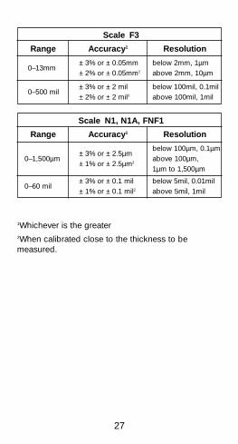
1Whichever is the greater2When calibrated close to the thickness to bemeasured.
Scale F3
Range Accuracy1 Resolution
0–13mm±3% or ±0.05mm below 2mm, 1µm±2% or ±0.05mm2 above 2mm, 10µm
0–500 mil±3% or ±2 mil below 100mil, 0.1mil±2% or ±2 mil2 above 100mil, 1mil
Scale N1, N1A, FNF1
Range Accuracy1 Resolution
±3% or ±2.5µmbelow 100µm, 0.1µm
0–1,500µm above 100µm,±1% or ±2.5µm2
1µm to 1,500µm
0–60 mil±3% or ±0.1 mil below 5mil, 0.01mil±1% or ±0.1 mil2 above 5mil, 1mil
28
Pro
be
Typ
eM
inim
umM
inim
umH
ead
roo
mM
inim
umC
al F
oil
Co
nvex
Co
ncav
eS
amp
leVa
lue1
Sur
face
Sur
face
Dia
met
erD
iam
eter
Rad
ius
Sep
arat
e Fe
rro
usF1
(or
F1 2
set
for
F1 o
pera
tion)
4mm
(0.
16”)
25m
m (
0.98
”)85
mm
(3.
35”)
4mm
(0.
16”)
250µ
m (
10m
il)F2
(or
F1 2
set
for
F2 o
pera
tion)
4mm
(0.
16”)
25m
m (
0.98
”)85
mm
(3.
35”)
4mm
(0.
16”)
1mm
(40
mil)
F1
Rig
ht A
ngle
4mm
(0.
16”)
25m
m (
0.98
”)25
mm
(0.
98”)
4mm
(0.
16”)
250µ
m (
10m
il)F1
2 R
ight
Ang
le4m
m (
0.16
”)25
mm
(0.
98”)
25m
m (
0.98
”)4m
m (
0.16
”)1m
m (
40m
il)F1
Tel
esco
pic
4mm
(0.
16”)
25m
m (
0.98
”)30
mm
(1.
18”)
4mm
(0.
16”)
250µ
m (
10m
il)F1
2 T
eles
copi
c4m
m (
0.16
”)25
mm
(0.
98”)
30m
m (
1.18
”)4m
m (
0.16
”)1m
m (
40m
il)F3
15m
m (
0.59
”)40
mm
(1.
57”)
85m
m (
3.35
”)22
mm
(0.
87”)
2.5m
m 1
00m
il)
Sep
arat
e N
on-
Ferr
ous
N1
22m
m (
0.87
”)25
mm
(0.
98”)
90m
m (
3.54
”)10
mm
(0.
39”)
250µ
m (
10m
il)N
1 R
ight
Ang
le22
mm
(0.
87”)
25m
m (
0.98
”)25
mm
(0.
98”)
10m
m (
0.39
”)25
0µm
(10
mil)
N1A
Ano
dise
r’s P
robe
TBA
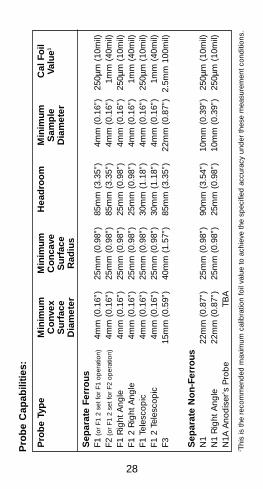
Pro
be
Cap
abili
ties:
1 Thi
s is
the
reco
mm
ende
d m
axim
um c
alib
ratio
n fo
il va
lue
to a
chie
ve th
e sp
ecifi
ed a
ccur
acy
unde
r th
ese
mea
sure
men
t con
ditio
ns.
29
Pro
be
Typ
eM
inim
umM
inim
umH
ead
roo
mM
inim
umC
al F
oil
Co
nvex
Co
ncav
eS
amp
leVa
lue1
Sur
face
Sur
face
Dia
met
erD
iam
eter
Rad
ius
Sep
arat
e D
ual F
NF
FNF1
(N
)44
mm
(1.
73”)
50m
m (
1.96
”)90
mm
(3.
54”)
18m
m (
0.71
”)25
0µm
(10
mil)
FNF1
(F)
8mm
(0.
31”)
50m
m (
1.96
”)90
mm
(3.
54”)
8mm
(0.
31”)
250µ
m (
10m
il)
FNF1
Rig
ht A
ngle
(N
)44
mm
(1.
73")
50m
m (
1.96
”)25
mm
(0.
96")
18m
m (
0.71
")25
0µm
(10
mil)
FNF1
Rig
ht A
ngle
(F)
8mm
(0.
31")
50m
m (
1.96
”)25
mm
(0.
96")
8mm
(0.
31")
250µ
m (
10m
il)
Inte
gra
lF1
(or
F1 2
set
for
F1 o
pera
tion)
4mm
(0.
16”)
25m
m (
0.98
”)13
0mm
(5.
1”)
4mm
(0.
16”)
250µ
m (
10m
il)F2
(or
F1 2
set
for
F2 o
pera
tion)
4mm
(0.
16”)
25m
m (
0.98
”)13
5mm
(5.
3”)
4mm
(0.
16”)
1mm
(40
mil)
F3TB
AN
1 (N
)22
mm
(0.
87”)
25m
m (
0.98
”)13
0mm
(5.
1”)
10m
m (
0.39
”)25
0µm
(10
mil)
FNF1
(N
)44
mm
(1.
73”)
50m
m (
1.96
”)13
5mm
(5.
3”)
18m
m (
0.70
”)25
0µm
(10
mil)
FNF1
(F)
8mm
(0.
31”)
50m
m (
1.96
”)13
5mm
(5.
3”)
8mm
(0.
31”)
250µ
m (
10m
il)
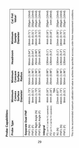
Pro
be
Cap
abili
ties:
1 Thi
s is
the
reco
mm
ende
d m
axim
um c
alib
ratio
n fo
il va
lue
to a
chie
ve th
e sp
ecifi
ed a
ccur
acy
unde
r th
ese
mea
sure
men
t con
ditio
ns.

30
Pro
be
Typ
eM
inim
umM
inim
umH
ead
roo
mM
inim
umC
al F
oil
Co
nvex
Co
ncav
eS
amp
leVa
lue1
Sur
face
Sur
face
Dia
met
erD
iam
eter
Rad
ius
PIN
1PF1
(or
F1 2
set
for
F1 o
pera
tion)
4mm
(0.
16”)
25m
m (
0.98
”)15
5mm
(6.
1”)
4mm
(0.
16”)
250µ
m (
10m
il)F2
(or
F1 2
set
for
F2 o
pera
tion)
4mm
(0.
16”)
25m
m (
0.98
”)16
0mm
(6.
3”)
4mm
(0.
16”)
1mm
(40
mil)
F3TB
AN
122
mm
(0.
87”)
25m
m (
0.98
”)16
0mm
(6.
3”)
10m
m (
0.39
”)25
0µm
(10
mil)
FNF1
(N
)44
mm
(1.
73”)
50m
m (
1.96
”)16
5mm
(6.
5”)
18m
m (
0.70
”)25
0µm
(10
mil)
FNF1
(F)
8mm
(0.
31”)
50m
m (
1.96
”)16
5mm
(6.
5”)
8mm
(0.
31”)
250µ
m (
10m
il)
Pro
be
Cap
abili
ties:
1 Thi
s is
the
reco
mm
ende
d m
axim
um c
alib
ratio
n fo
il va
lue
to a
chie
ve th
e sp
ecifi
ed a
ccur
acy
unde
r th
ese
mea
sure
men
t con
ditio
ns.

31
10 ACCESSORIESSome of the following items are optional. However,some are consumable items that may need to bereplaced over the lifetime of the gauge.
Dry Batteries:T4569329- 2 off Alkaline Cells (AAA)
Foil Sets:T9904199F 1mm (40 mil) 8 piecesT9904199G 1mm (40 mil) 3 piecesT9904199J 5mm (200 mil) 4 piecesT9904199K 13mm (500 mil) 4 piecesT9904199N 1.5mm (60 mIl) 3 pieces
Individual foils in the range 12.5µm (0.5 mil) to 8mm(315 mil) and customised sets chosen from this rangeare also available. Consult your local Elcometer Dealer.
Calibration Certificates:Certificates traceable to National Standards includingUKAS and NIST are available on request.
Test Certificates:A certificate with results of a standard test on knownfoil values over the full range of the probe. Order usingPart No. TEST-456
Coated Thickness Standards including CertificateT995111261 Ferrous Standard (4 Values)T999111271 Non-Ferrous Standard (4 Values)
T995 TBA Ferrous Standard (2 Values)T995 TBA Non-Ferrous Standard (2 Values)

32
Probe Positioning JigT95012880
Probe Adapters: (Standard F & N Probes Only)T4567766- Jumbo Hand GripT4567381- V Adapter (for pipes)
Printer Lead:T45616267 456 to Printer Connection Cable
(25-pin)
Printers:INFRARED PORTABLE PRINTERX45613877 Hewlett Packard (HP) Infrared
Portable PrinterT45613878 HP Thermal Printer Paper
MINIPRINTER42 column, rechargeable battery powered Miniprintercomplete with cable in three charger options
X4569964B 230V (UK Plug)X4569964C 230V (European Plug)X4569964D 110V (US Plug)
MINIPRINTER SPAREST45616267 456 to printer connection leadT9769992- Ribbon Cassettes (Pack of 5)T9769993- Paper Rolls (Box of 20)
Bench StandsT45616161 Integral Probe VersionT45616162 Integral/Separate Probe Version
PC LeadT45616217 456 to PC Connection Lead (9-pin)
NOTE: A 9-pin to 25-pin adapter may be required forcertain PC RS232 ports.
33
11 GLOSSARYAbout: Information screens for probe and gaugewithin the Main menu.
Auto Batching: Memory for readings with the batchnumber automatically determined by the gauge. (Toponly)
Automatic Mode: Setting for Dual FNF probe so thatthe substrate type is determined automatically.
Average Mode: A data collection method where theuser determines the subgroup size. (Standard and Toponly)
Back: Softkey control that returns gauge to theprevious screen without any change to settings.
Backlight: Illumination for the display that can beswitched on or off by the user.
Basic: One of the three feature versions of the gaugewith simple statistics but no memory for readings.
Batching: Collection of reading data in groups to alloweasier analysis of large structures or complexassemblies. (Standard and Top only)
Calibration Adjustment: Setting the gauge to knownvalues of thickness to ensure accuracy on differentsubstrate types, shapes and surface finishes.
Calibration Foils: Coating thickness standardsmeasured using techniques independent of the gaugefor setting known values of thickness on the substrateto be measured.
Calibration Method: Adjustment technique for thegauge dependant on the condition of the substrate tobe measured, e.g. smooth surface calibration, roughsurface calibration, etc.
34
Coated Standards: Thickness standards using typicalsubstrate materials coated with hardwearing materialsand measured using techniques independent of thegauge.
Coefficient of Variation: The standard deviationdivided by the mean for a group of readings,expressed as a percentage.
Combined Statistics: FNF operation statistics arekept separately for F and N readings unless thecombined statistics is activated, also applies to F1 2operation.
Counted Average Mode: A data collection methodusing a pre-set number of readings for each sub-group. The gauge records the average of the group asa single value, e.g. for a counted average set to threereadings, the gauge records the average of eachgroup of three readings in turn. (Standard and Top only)
Current Batch: The active batch when data is beingcollected.
Current Statistics: The statistical values for the activebatch.
Delete: Cancellation of an individual reading, a batchof readings or the whole memory of readings andstatistical data.
EDCS: The Windows® based Elcometer DataCollection software also available as EDCS+.(Standard and Top only)
EDTS: A data transfer software for uploading readingsfrom the memory of a gauge to a spreadsheet, alsoknown as EDTS ExceI® Link. (Standard and Top only)
35
Error Message: Text message displayed on the LCDscreen when an operational error has been detected,e.g. gauge switched on with no probe connected, printfunction selected with no connection to the printer.Pressing any of the four softkeys normally clears thesemessages.
ESC: Abbreviation for escape. This softkey controlreturns the gauge to the Reading Screen from theCalibration Procedure without making any changes.
F: Abbreviation for Ferrous substrate, i.e. a magneticmetal onto which a coating is applied.
Factory Calibration: Calibration values set when theprobe is manufactured. These settings can be recalledby the User in the RESET menu. NOTE: FACTORYCALIBRATION will not necessarily restore precisecalibration values. So calibration adjustment isrecommended after FACTORY CALIBRATION isimplemented.
Ferrous: The measurement method applicable tocoatings on magnetic metals such as steel, cast iron,etc. The Elcometer 456 uses the electromagneticinduction principle to determine the coating thicknesson Ferrous substrates.
FNF: Abbreviation for the dual Ferrous/Non-Ferrousprobe option.
Highest Reading: The value for the greatest thicknessin a group of readings.
Integral Probe: The probe option where the probe isfixed to the case of the gauge without any externalcable. Appropriate for one handed operation of thegauge.

36
International Gauge Setting: Default settings for thegauge for all areas except the USA. Sets the units tometric, the calendar to DD/MM/YY format and all othersettings to the default condition.
Limits: Upper and lower values that can be set by theuser to monitor specification values. (Standard and Toponly)
Lowest Reading: The value for the least thickness in agroup of readings.
Manual Mode: The setting for the dual function FNFprobe that makes the probe function as either an Fonly or a N only probe, as opposed to the automaticmode.
Mean: The average of a group of readings, the sum ofthe individual readings divided by the number ofreadings.
Memory: The feature of the Elcometer 456 Standardand Top options that allows individual readings to bestored for recording and/or analysis.
Menu Operation: The Elcometer 456 operates usinguser-selected options from a series of menus. Thegraphical display allows text and images to bedisplayed to aid operation of the various gaugeprocedures and features.
N: Abbreviation for Non-Ferrous substrate, i.e. non-magnetic metals to which a non-conductive coating isapplied.
Non-Ferrous: The measurement method applicable tocoatings on non-magnetic metals such as aluminium,copper, some types of stainless steel, etc. TheElcometer 456 uses the eddy current principle todetermine the coating thickness on Non-Ferroussubstrates
37
Normal Mode: A data collection method where thegauge records individual readings. (Standard and Toponly)
Number of Readings: The running value for thenumber of readings taken in a group. In the case of theaveraging or counted average, the Number ofReadings is the number of values recorded not thetotal number of readings taken.
Opening Screen: The screen that is displayed whenthe gauge is switched on. This screen can be switchedoff under user control.
Output: The data stream from the memory of thegauge sent via the data port to a computer or asuitable printer. (Standard and Top only)
PINIP: The Plug IN Integral Probe option for theseparate probe gauge types. This is a separate probeoption without the cable and therefore allows one-handed operation.
Print: The formatted data output suitable for serialprinters and includes headers and space for writtenuser notes. (Standard and Top only)
Recalibration: Readjustment of the gauge settings forzero and/or known values of thickness usingcalibration foils or coated standards.
Reset: The ability to return the gauge to defaultsettings for the operational features, an option on theMain Menu.
Reading Screen: The screen where readings aredisplayed. This screen can include statistics if selectedand batch information if in use.
38
SEL: Abbreviation for Select. This softkey controlselects the option displayed. In some cases pressingSEL puts a tick in to the tick box to indicate that thefeature is selected, e.g. Backlight on.
Separate Probe: The probe option where the probe isattached to the gauge via a cable and connector.These probes are interchangeable and allowmaximum flexibility of operation and access.
Setup: The ability to select and/or adjust the gaugefeatures via the menus. Features in the Setup menuare Calibration Method, Statistics, Backlight, Probe,Units, Output, Beep Volume, Language, Auto SwitchOff and Opening Screen.
Softkeys: The flexible control feature that allows thefour controls to vary their function depending on thelocation in the gauge software. Each screen has itsown set of control functions.
Software: Elcometer support for gauges with RS232output, see EDCS and EDTS. (Standard and Top only)
Standard: One of the three feature versions of thegauge with a single batch memory for upto 250readings.
Standard Deviation: A statistical measure of thespread of values in a group of readings.
Statistics: Number of readings, mean, standarddeviation, coefficient of variation, highest and lowestreading can all be displayed or a selection from this listdisplayed as required.
Substrate: The base material onto which the coating isapplied. In the case of the Elcometer 456 the substratewill always be a metal.
39
Top: One of the three feature versions of the gaugewith capacity for storage of upto 40,000 readings inupto 999 batches.
USA Gauge Setting: Default settings for the gauge forthe USA. Sets the units to imperial, the calendar toMM/DD/YY format and all other settings to defaultcondition.
Zero Offset: Correction method for measurement ofcoatings applied to rough surfaces. A value issubtracted from each reading to compensate for theeffects of the rough surface; the value depends on theactual profile. This method is also known as the ISOmethod, the Australian National Standard method andthe SSPC method.