operating instructions electrical part turn actuator€¦ · · 2015-04-27electrical part turn...
TRANSCRIPT
Operating Instructions 42/68-151-EN
Electrical Part Turn ActuatorPME120-AI/AN (Contrac)
Pos: 1 /Titelblätter / Copyright/BA-IA/Aktorik/Antriebe/Contrac/PME120-AI/-AN @ 18\mod_1203591384140_3101.doc @ 163857
For continuous positioning,Rated torque 100 Nm (80 lbf-ft),
with integrated electronics or for use with separate electronic unit

Blinder Text
2 PME120-AI/AN (Contrac) 42/68-151-EN
Pos: 2 /Titelblätter / Copyright/Copyright-Seite @ 0\mod_1138781938968_3101.doc @ 3122
Electrical Part Turn Actuator
PME120-AI/AN (Contrac)
Operating Instructions 42/68-151-EN
06.2008
Rev. D
Manufacturer: ABB Automation Products GmbH Schillerstraße 72 32425 Minden Germany Tel.: +49 551 905-534 Fax: +49 551 905-555 [email protected]
© Copyright 2008 by ABB Automation Products GmbH Subject to change without notice
This document is protected by copyright. It assists the user with the safe and efficient operation of the device. The contents may not be copied or reproduced in whole or in excerpts without prior approval of the copyright holder.
Pos: 3 /Inhaltsverzeichnis/Inhaltsverzeichnis für alle Dokumente @ 0\mod_1138710310890_3101.doc @ 3129 Contents
Contents
42/68-151-EN PME120-AI/AN (Contrac) 3
1 Safety....................................................................................................................................................................5
1.1 General Safety Information ............................................................................................................................5 1.2 Technical limits...............................................................................................................................................5 1.3 Warranty provision .........................................................................................................................................6 1.4 Labels and symbols........................................................................................................................................6
1.4.1 Symbols and warnings ............................................................................................................................6 1.4.2 Name plate..............................................................................................................................................7
1.5 Operator liability .............................................................................................................................................7 1.6 Personnel qualification ...................................................................................................................................7 1.7 Returning devices...........................................................................................................................................8 1.8 Disposal..........................................................................................................................................................8
1.8.1 Information on WEEE directive 2002/96/EC (Waste Electrical and Electronic Equipment) ...................8 1.9 Transport safety information ..........................................................................................................................8 1.10 Storage conditions..........................................................................................................................................9 1.11 Installation safety information.........................................................................................................................9 1.12 Electrical installation safety information .......................................................................................................10 1.13 Operating safety information ........................................................................................................................10 1.14 Maintenance safety information ...................................................................................................................10
2 Design and function..........................................................................................................................................11 3 Installation..........................................................................................................................................................12
3.1 Actuator check..............................................................................................................................................12 3.2 Mounting position .........................................................................................................................................12 3.3 Installation instructions .................................................................................................................................13 3.4 Assembly with the valve ...............................................................................................................................13
3.4.1 Preparation for mounting with lever ......................................................................................................13 3.4.2 Preparation for mounting with direct adapter ........................................................................................15
3.5 Mounting examples ......................................................................................................................................16 3.5.1 Fastening elements...............................................................................................................................16 3.5.2 Mounting with lever ...............................................................................................................................16 3.5.3 Lever PME120-AI/-AN...........................................................................................................................17 3.5.4 Direct adapter PME120-AI/-AN.............................................................................................................19
4 Electrical connection ........................................................................................................................................20 4.1 Cable shield..................................................................................................................................................20
4.1.1 Signal part .............................................................................................................................................20 4.2 Integrated Electronic Unit AI (standard) .......................................................................................................21 4.3 Integrated Electronic Unit AI (bus communication)......................................................................................21 4.4 Electronic unit in field mount EAN823 (standard) ........................................................................................22 4.5 Electronic unit in field mount EAN823 (bus communication) .......................................................................23 4.6 Configuration of digital input/output signals (standard control) ....................................................................23

Contents
4 PME120-AI/AN (Contrac) 42/68-151-EN
4.6.1 Standard................................................................................................................................................23 4.6.2 Downstream from step controller ..........................................................................................................24
5 Local operation..................................................................................................................................................25 5.1 General information on operation.................................................................................................................25 5.2 Operating elements of the service field (ISF)...............................................................................................26
6 Commissioning and service field (ISF) ...........................................................................................................27 6.1 Typical commissioning with the service field (ISF) ......................................................................................27
6.1.1 Status ....................................................................................................................................................27 6.1.2 Opening the cover flap of the ISF .........................................................................................................27 6.1.3 Operating mode "Device setup"............................................................................................................27 6.1.4 Setup via user interface ........................................................................................................................27 6.1.5 Defining the initial position (0 % or 100 %) ...........................................................................................28 6.1.6 Defining the second position (0 % or 100 %)........................................................................................28 6.1.7 Saving your settings..............................................................................................................................28 6.1.8 Correcting settings ................................................................................................................................29 6.1.9 Signals on the commissioning and service field (ISF) ..........................................................................29
6.2 Positions for the potential switch..................................................................................................................30 6.3 Fuses for integrated actuator electronic unit ................................................................................................30
6.3.1 Installation locations for fuses...............................................................................................................31 7 Operation............................................................................................................................................................32
7.1 Automatic / manual mode.............................................................................................................................32 7.2 Manual operation..........................................................................................................................................32
8 Maintenance.......................................................................................................................................................33 8.1 Inspection and overhaul ...............................................................................................................................33 8.2 Brake adjustment .........................................................................................................................................34 8.3 Oil change ....................................................................................................................................................34 8.4 Filling capacity..............................................................................................................................................34
9 Alarms / Errors...................................................................................................................................................35 9.1 Definition ......................................................................................................................................................35
9.1.1 Alarms ...................................................................................................................................................35 9.1.2 Error ......................................................................................................................................................35
9.2 Alarm diagram ..............................................................................................................................................36 9.3 Error diagram ...............................................................................................................................................37
10 Trouble shooting ...............................................................................................................................................38 10.1 Electrical test values.....................................................................................................................................39
11 Technical data....................................................................................................................................................40 11.1 General information......................................................................................................................................40
12 Appendix ............................................................................................................................................................41 12.1 Permits and certifications .............................................................................................................................41
13 Index ...................................................................................................................................................................43

Safety
42/68-151-EN PME120-AI/AN (Contrac) 5
Pos: 4.1 /Überschriften/1/S - U/Sicherheit @ 0\mod_1129703894050_3101.doc @ 3168
1 Safety Pos: 4.2 /Sicherheit/Allgemein/Allgemeines zur Sicherheit @ 0\mod_1129703939516_3101.doc @ 3260
1.1 General Safety Information
The “Safety” chapter provides an overview of the safety aspects to be observed for the operation of the device.
The device is built based on state-of-the-art technology and is operationally safe. It was tested and left the factory in a proper state. The requirements in the manual as well as the documentation and certificates must be observed and followed in order to maintain this state for the period of operation.
The general safety requirements must be complied with completely during operation of the device. In addition to the general information, the individual chapters of the manual contain descriptions about processes or procedural instructions with specific safety information.
Only the observance of all safety information enables the optimal protection of personnel as well as the environment from hazards and the safe and trouble-free operation of the device.
Pos: 4.3 /Sicherheit/Aktorik/Antriebe/Allgemein/Bestimmungsgemäße Verwendung @ 16\mod_1197272116328_3101.doc @ 144907
The actuators are used for operating final control elements (valves, vanes, etc.). They may only be operated using the appropriate Contrac electronic unit. Do not use these actuators for any other purpose. Otherwise, a hazard of personal injury or of damage to or impairment of the operational reliability of the device may arise. In addition to these operating instructions, the relevant documentation for the electronic unit and software tools must be observed.
Pos: 4.4 /Sicherheit/Allgemein/Hinweis zur bestimmungswidrigren Verwendung (Wartung/Reparatur) @ 0\mod_1129707002440_3101.doc @ 3240
Repairs, alterations and enhancements or the installation of replacement parts is only permissible as far as described in the manual. Further actions must be verified with ABB Automation Products GmbH. Excluded from this are repairs performed by ABB-authorized specialist shops.
Pos: 4.5 /Sicherheit/Allgemein/Technische Grenzwerte BA @ 0\mod_1140156564953_3101.doc @ 3252
1.2 Technical limits
The device is designed for use exclusively within the stated values on the name plate and in the technical specifications (see "Technical Specifications” chapter and data sheet). These must be complied with accordingly, e.g.:
• The maximum operating temperature may not be exceeded.
• The permitted operating temperature may not be exceeded.
• The housing protection system must be observed.
Pos: 4.6 /======= Seitenumbruch ======== @ 0\mod_1126532365768_3101.doc @ 3830

Safety
6 PME120-AI/AN (Contrac) 42/68-151-EN
Pos: 4.7 /Sicherheit/Allgemein/Gewährleistungsbestimmungen @ 0\mod_1129706207246_3101.doc @ 3261
1.3 Warranty provision
A use contrary to the device’s stipulated use, disregarding of this manual, the use of under-qualified personnel as well as unauthorized alterations excludes the manufacturer of liability from any resulting damages. The manufacturer’s warranty expires.
Pos: 4.8 /Überschriften/1.1/1-spaltig/S - U/Schilder und Symbole @ 0\mod_1129721947139_3101.doc @ 3204
1.4 Labels and symbols Pos: 4.9 /Überschriften/1.1.1/1-spaltig/Symbole und Signalwörter @ 20\mod_1208422698260_3101.doc @ 180868
1.4.1 Symbols and warnings Pos: 4.10 /Sicherheit/Allgemein/Symbole und Signalwörter @ 20\mod_1208422453167_3101.doc @ 180843
Danger – <Serious damage to health / risk to life>
One of these symbols in conjunction with the “Danger“ warning indicates an imminent danger. If it is not avoided, death or serious injury will result.
Warning – <Bodily injury> The symbol in conjunction with the “Warning“ message indicates a possibly dangerous situation. If it is not avoided, death or serious injury could result.
Caution – <Slight injuries> The symbol in conjunction with the “Caution“ message indicates a possibly dangerous situation. If it is not avoided, slight or minor injury can result. May also be used for property damage warnings.
Notice – <Property damage>!
The symbol indicates a possibly damaging situation. If it is not avoided, the product or something in its area can be damaged.
Important
The symbol indicates operator tips or especially useful information. This is not a message for a dangerous or damaging situation.
Pos: 4.11 /======= Seitenumbruch ======== @ 0\mod_1126532365768_3101.doc @ 3830

Safety
42/68-151-EN PME120-AI/AN (Contrac) 7
Pos: 4.12 /Überschriften/1.1.1/1-spaltig/Typenschild @ 0\mod_1140617210906_3101.doc @ 3227
1.4.2 Name plate Pos: 4.13 /Sicherheit/Aktorik/Antriebe/Elektr. Schwenkantriebe/PME120/Typenschild @ 18\mod_1204020550687_3101.doc @ 165125
Fig. 1 1 Complete model name 2 Fabrication no./ NL no. (no. of non-
standard version) 3 Output torque / Year of manufacture 4 Permissible ambient temperature and
protection class / CE mark 5 min./max. crank angle and max.
actuating speed
6 Filled oil types 7 Associated Contrac electronic unit 8 Permissible voltage range / mains
frequency (for PME120-AI only) 9 Power consumption / specifications for
fuse protection (for PME120-AI only) 10 Blank for customer-specific entry
Pos: 4.14 /Sicherheit/Aktorik/Allgemein/Pflichten des Betreibers @ 10\mod_1181723170562_3101.doc @ 105157
1.5 Operator liability
The operators must strictly observe the applicable national regulations in their countries with regards to installation, function tests, repairs, and maintenance of electrical devices.
Pos: 4.15 /Sicherheit/Allgemein/Organisatorische Maßnahmen/Qualifikation des Personals @ 0\mod_1129728800194_3101.doc @ 3247
1.6 Personnel qualification
The installation, commissioning and maintenance of the device may only be carried out through trained specialist personell authorized by the plant operator. The specialist personnel must have read and understood the manual and comply with its instructions.
Pos: 4.16 /======= Seitenumbruch ======== @ 0\mod_1126532365768_3101.doc @ 3830

Safety
8 PME120-AI/AN (Contrac) 42/68-151-EN
Pos: 4.17 /Sicherheit/Allgemein/Organisatorische Maßnahmen/Rücksendung von Geräten @ 0\mod_1129730744499_3101.doc @ 3248
1.7 Returning devices
Use the original packaging or a suitably secure packaging for returning the device for repair or for recalibration. Include the properly filled out return form (see attachment) with the device.
According to EC guidelines for hazardous materials, the owner of hazardous waste is responsible for its disposal or must observe the following regulations for its shipping:
All delivered devices to ABB Automation Products GmbH must be free from any hazardous materials (acids, alkali, solvents, etc.).
Pos: 4.18 /Sicherheit/Allgemein/Organisatorische Maßnahmen/Entsorgung @ 10\mod_1176447410937_3101.doc @ 81544
1.8 Disposal
ABB Automation Products GmbH actively promotes environmental consciousness and has an operational management system in accordance with DIN EN ISO 9001:2000, EN ISO 14001:2004 and OHSAS 18001. Our products and solutions should have minimum impact on the environment and persons during manufacture, storage, transport, use and disposal.
This includes the environmentally friendly use of natural resources. Through its publications ABB conducts an open dialog with the public.
This product/solution is manufactured from materials that can be reused by specialized recycling companies.
1.8.1 Information on WEEE directive 2002/96/EC (Waste Electrical and Electronic Equipment)
This product/solution is not subject to the WEEE directive 2002/96/EC and relevant national laws (e.g., ElektroG in Germany).
Dispose of the product/solution directly in a specialized recycling facility and do not use the municipal garbage. Only privately used products may be disposed of in the municipal garbage according to the WEEE directive 2002/96/EC. Proper disposal prevents negative effects on people and the environment, and supports the reuse of valuable raw materials.
If it is not possible to dispose of old equipment properly, ABB Service can accept and dispose of returns for a fee.
Pos: 4.19 /Überschriften/1.1/1-spaltig/S - U/Sicherheitshinweise zum Transport @ 0\mod_1140166475703_3101.doc @ 3206
1.9 Transport safety information Pos: 4.20 /Transport/Allgemein/Prüfung @ 0\mod_1129815371197_3101.doc @ 3317
Check the devices for possible damage that may have occurred during transport. Damages in transit must be recorded on the transport documents. All claims for damages must be claimed without delay against the shipper and before the installation.
Pos: 4.21 /======= Seitenumbruch ======== @ 0\mod_1126532365768_3101.doc @ 3830
Safety
42/68-151-EN PME120-AI/AN (Contrac) 9
Pos: 4.22 /Überschriften/1.1/1-spaltig/J - L/Lagerbedingungen @ 8\mod_1176907016921_3101.doc @ 84229
1.10 Storage conditions Pos: 4.23 /Sicherheit/Aktorik/Antriebe/Elektr. Schwenkantriebe/Allgemein/Lagerbedingungen @ 9\mod_1181415663015_3101.doc @ 102780
The actuators may be stored under moist and aggressive condition for a short time. The equipment is protected against external corrosive influences. However, direct exposure to rain, snow, etc., must be avoided.
Actuators, equipped with an anti condensation heater, are additionally protected by desiccant, which is placed in the following locations:.
Position sensor: in connection chamber
electronic unit (separately supplied): electrical connection area The desiccant guarantees sufficient protection for approximately 150 days. It can be regenerated at a temperature of 90 °C (114 °F) within 4 h.
Important Remove the desiccant prior to commissioning the actuator or the electronic unit.
If you intend to store or transport the device for a longer time, we recommend that you wrap it in plastic foil and add desiccant. Regularly check whether the desiccant is still active.
Pos: 4.24 /Überschriften/1.1/1-spaltig/S - U/Sicherheitshinweise zur Montage @ 0\mod_1140166528109_3101.doc @ 3208
1.11 Installation safety information Pos: 4.25 /Sicherheit/Aktorik/Antriebe/Allgemein/Sicherheitshinweise zur Montage (2008-05-07 13:42:13) @ 10\mod_1181563348656_3101.doc @ 102853
• The actuators perform movements for positioning vanes and valves, etc.
• Only qualified specialists who have been trained for these tasks are authorized to mount and adjust the control actuator, and to make the electrical connection.
• When working on the actuator itself or the electronics always observe the locally valid accident prevention regulations and the regulations concerning the construction of technical installations.
• The eyebolt at the top of the actuator may only be used to lift or lower the actuator vertically.
• Do not use the handwheel to lift or to lower the actuator..
• Do not use it if the actuator is mounted at the valve! Make sure that the final control element is not exposed to process forces.
Pos: 4.26 /======= Seitenumbruch ======== @ 0\mod_1126532365768_3101.doc @ 3830
Safety
10 PME120-AI/AN (Contrac) 42/68-151-EN
Pos: 4.27 /Überschriften/1.1/1-spaltig/S - U/Sicherheitshinweise zur elektrischen Installation @ 0\mod_1140166567843_3101.doc @ 3207
1.12 Electrical installation safety information Pos: 4.28 /Sicherheit/Allgemein/Sicherheitshinweise zur elektrischen Installation @ 13\mod_1191930430247_3101.doc @ 128893
The electrical connection may only be performed by authorized specialist personnel according to the electrical plans.
Comply with electrical connection information in the manual. Otherwise, the electrical protection class can be affected. The secure separation of contact-dangerous electrical circuits is only guaranteed when the connected devices fulfill the requirements of the DIN EN 61140 (VDE 0140 Part 1) (basic requirements for secure separation). For secure separation, run the supply lines separated from contact-dangerous electrical circuits or additionally insulate them.
Pos: 4.29 /Überschriften/1.1/1-spaltig/S - U/Sicherheitshinweise zum Betrieb @ 0\mod_1140166424437_3101.doc @ 3205
1.13 Operating safety information Pos: 4.30 /Sicherheit/Aktorik/Antriebe/Elektr. Schwenkantriebe/Allgemein/Sicherheitshinweise zum Betrieb RHD @ 18\mod_1204884114406_3101.doc @ 168542
Warning - risk of injury! Note that the actuator position may be changed accidentally by the repelling power of the valve when the brake is released! Make sure that process forces are not exerted on the lever.
Before switching on the device, ensure that the specified environmental conditions in the “Technical Specifications” chapter or data sheet are complied with and that the power supply voltage corresponds with the power electronic unit.
If there is a chance that safe operation is no longer possible, take the unit out of operation and secure against unintended startup.
When mounting the actuator in areas that may be accessed by unauthorized persons, take the required protective measures.
Switch off the power supply to the motor for manual operation.
Pos: 4.31 /Überschriften/1.1/1-spaltig/S - U/Sicherheitshinweise zur Wartung @ 10\mod_1181811822343_3101.doc @ 106052
1.14 Maintenance safety information Pos: 4.32 /Sicherheit/Aktorik/Antriebe/Allgemein/Sicherheitshinweise zur Wartung (2008-05-07 14:15:45) @ 10\mod_1181812046750_3101.doc @ 106075
• When changing the oil of the actuator, thoroughly remove any oil that may have run down on the floor during the procedure to avoid accidents.
• Dispose of the waste oil in compliance with the respective local regulations. Make sure that no oil reaches the water cycle.
• Switch off the supply voltage for the power electronic unit and separate anti-condensation heater (option) when working on the actuator or related subassemblies and take precautions to prevent unintentional switch-on.
• Make sure that any oil leaking from the device cannot come into contact with hot parts
Pos: 5 /======= Seitenumbruch ======== @ 0\mod_1126532365768_3101.doc @ 3830
Design and function
42/68-151-EN PME120-AI/AN (Contrac) 11
Pos: 6.1 /Überschriften/1/A - C/Aufbau und Funktion @ 0\mod_1129797620733_3101.doc @ 3140
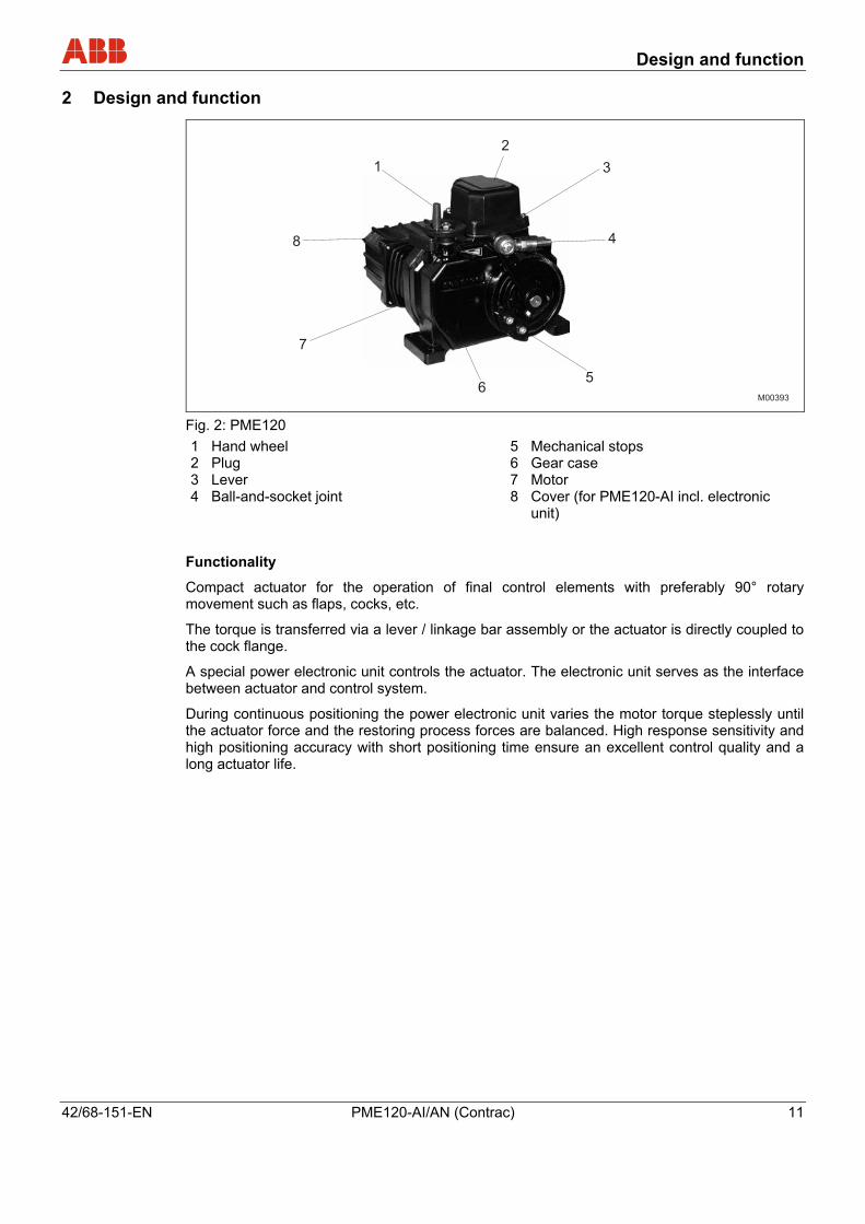
2 Design and function Pos: 6.2 /Aufbau und Funktion/Aktorik/Antriebe/Elektr. Schwenkantriebe/PME120/Aufbau PME120 @ 18\mod_1204022385203_3101.doc @ 165175
Fig. 2: PME120 1 Hand wheel 2 Plug 3 Lever 4 Ball-and-socket joint
5 Mechanical stops 6 Gear case 7 Motor 8 Cover (for PME120-AI incl. electronic
unit)
Pos: 6.3 /Aufbau und Funktion/Aktorik/Antriebe/Elektr. Schwenkantriebe/Allgemein/Konzept @ 15\mod_1195050522390_3101.doc @ 140463
Functionality
Compact actuator for the operation of final control elements with preferably 90° rotary movement such as flaps, cocks, etc.
The torque is transferred via a lever / linkage bar assembly or the actuator is directly coupled to the cock flange.
A special power electronic unit controls the actuator. The electronic unit serves as the interface between actuator and control system.
During continuous positioning the power electronic unit varies the motor torque steplessly until the actuator force and the restoring process forces are balanced. High response sensitivity and high positioning accuracy with short positioning time ensure an excellent control quality and a long actuator life.
Pos: 7 /======= Seitenumbruch ======== @ 0\mod_1126532365768_3101.doc @ 3830

Installation
12 PME120-AI/AN (Contrac) 42/68-151-EN
Pos: 8.1 /Überschriften/1/M - O/Montage @ 0\mod_1140519732218_3101.doc @ 3159
3 Installation Pos: 8.2 /Überschriften/1.1/1-spaltig/A - C/Antriebskontrolle @ 10\mod_1181632527031_3101.doc @ 103415
3.1 Actuator check Pos: 8.3 /Montage/Aktorik/Elektr. Schwenkantriebe/Allgemein/Antriebskontrolle RHD/PME @ 16\mod_1197272853218_3101.doc @ 144955
Before you start to install the actuator make sure that the delivery status corresponds to the ordered status and to the intended use.
• Check the oil level when installing the device in positions other than IMB 3.
• Did you fasten the separately delivered venting plug in the uppermost bore (depending on the mounting orientation)?
• Make sure that the motor and the connection chambers are free of dirt, moisture and corrosion.
Pos: 8.4 /Überschriften/1.1/1-spaltig/D - F/Einbaulage @ 3\mod_1158651041937_3101.doc @ 41702
3.2 Mounting position Pos: 8.5 /Montage/Aktorik/Elektr. Schwenkantriebe/Allgemein/Einbaulage Zeich. RHD/PME @ 14\mod_1194260228968_3101.doc @ 135729
The spur gears of the actuator PME120-AI/AN (Contrac) are oil lubricated. They contain the max. oil quantity when leaving the manufacturer. Once the actuator is installed replace the uppermost check plug by the separately supplied venting plug.
IMB 3 IMB 6 IMB 7 IMB 8 IMV 6IMV 5
1 2
M00366 Fig. 3 1 Inspection plug 2 Venting plug
Pos: 8.6 /Montage/Aktorik/Elektr. Schwenkantriebe/PME120/Einbaulage @ 18\mod_1204707991984_3101.doc @ 167333
All mounting orientations shown in Fig. 3 are permissible. To facilitate mounting and maintenance, however, it is recommended that you use orientation IMB 3. For each mounting position, check the oil level prior to commissioning.
To ensure proper access to the electronic unit, maintain a minimum separation of 60 mm (2.36 inch).
Pos: 8.7 /======= Seitenumbruch ======== @ 0\mod_1126532365768_3101.doc @ 3830

Installation
42/68-151-EN PME120-AI/AN (Contrac) 13
Pos: 8.8 /Überschriften/1.1/1-spaltig/M - O/Montagehinweise @ 10\mod_1181632708234_3101.doc @ 103461
3.3 Installation instructions Pos: 8.9 /Montage/Aktorik/Elektr. Schwenkantriebe/RHD250...4000/Montagehinweise @ 16\mod_1197272970281_3101.doc @ 145009
• Make sure that the actuator is accessible from all sides to ensure convenient handwheel operation, electrical connection, and replacement of assemblies.
• Avoid direct exposure to rain, snow and other environmental influences.
• The actuators can withstand vibration loadings up to 150 Hz and max. 2 g acc. to EN 60068-2-6, table C2.
• Exclusively mount the actuator on a rigid, non-vibrating support to avoid relative motions between the actuator and the valve.
• Spring couplings or vibration absorbers in the coupling rod may cause additional load. The drive elements (lever, coupling rod) may not cause additional vibration loadings, which exceed the rated torque more than twice.
• The maximum rated torque of the actuator may not be permanently exceeded. A short-term overload (up to twice the rated torque) is possible.
• When mounting the actuator close to heat sources use an insulating layer or shielding.
• The ambient temperature may not be exceeded. If necessary, use an appropriate roof to avoid heat radiation.
Pos: 8.10 /Überschriften/1.1/1-spaltig/V - Z/Zusammenbau mit dem Stellglied @ 10\mod_1181634985953_3101.doc @ 103507
3.4 Assembly with the valve Pos: 8.11 /Überschriften/1.1.1/1-spaltig/Vorbereitung Montage mit Hebeltrieb @ 18\mod_1205935578140_3101.doc @ 171575
3.4.1 Preparation for mounting with lever Pos: 8.12 /Montage/Aktorik/Elektr. Schwenkantriebe/Allgemein/Vorbereitung @ 10\mod_1181569909062_3101.doc @ 103083
Warning – Electrical voltage risk! When working on the actuator or the related subassembly, switch off the supply voltage for the power electronic unit and separate anti-condensation heater (option), and take precautions to prevent unintentional switch-on.
1. Make sure that the shaft and lever bore surface are clean and free of grease.
2. Determine the length of the coupling tube (not included in the scope of delivery).
3. Move the valve to the "CLOSED" position.
4. Use the handwheel to move the actuator into the proper end position. Observe the permissible angle.
5. Refer to the dimensioned drawings for the required length of the connection pipe.
6. Drill a cone bore into the valve lever for mounting the second ball-and-socket joint, as shown in the dimensioned drawings section.
7. Insert the ball-and-socket joint, and secure with crown nut and split-pin.
8. Remove the welding bushings and weld them to the coupling tube.
9. Insert the link rod between the two ball-and-socket joints and screw it in.
10. If required adjust “L” by turning the link rod.
11. When all adjustment steps are finished, fasten the counter nuts.
Pos: 8.13 /======= Seitenumbruch ======== @ 0\mod_1126532365768_3101.doc @ 3830

Installation
14 PME120-AI/AN (Contrac) 42/68-151-EN
Pos: 8.14 /Überschriften/1.1.1.1/1-spaltig/Wegabhängige Anschlageinstellung @ 19\mod_1207653387468_3101.doc @ 178771
3.4.1.1 Adjusting the stops for travel Pos: 8.15 /Montage/Aktorik/Elektr. Schwenkantriebe/Allgemein/Wegabhängige Anschlageinstellung @ 10\mod_1181570388312_3101.doc @ 103106
1. Move the output lever / valve to the position requiring fine adjustment.
2. Put the stop onto the toothing as close to the output lever as possible and fasten it with screws.
3. The mechanical limit stops may not be fixed within the adjusted operating range.
4. Move the output lever towards the stop using the handwheel; turn the coupling rod for fine adjustment.
5. Fasten the counter nuts.
6. Fasten the stop in the other mounting position close to the end position, depending on the toothing.
Pos: 8.16 /Überschriften/1.1.1.1/1-spaltig/Kraftabhängige Anschlageinstellung @ 19\mod_1207653437593_3101.doc @ 178794
3.4.1.2 Adjusting the stops for torque Pos: 8.17 /Montage/Aktorik/Elektr. Schwenkantriebe/Allgemein/Kraftabhängige Anschlageinstellung @ 10\mod_1181570779703_3101.doc @ 103152
1. First proceed as described above for travel-dependent adjustment.
2. Prior to re-fastening the counter-nut provide pretension in the valve’s "CLOSED" position.
3. Lock the hand wheel.
4. Turn the coupling tube or slightly shift the limit stops to get a small gap between lever and limit stop.
5. The procedure and gap size depend on the stiffness of the linkage arrangement.
6. Tighten the counter-nuts and limit stop screws. Pos: 8.18 /======= Seitenumbruch ======== @ 0\mod_1126532365768_3101.doc @ 3830
Installation
42/68-151-EN PME120-AI/AN (Contrac) 15
Pos: 8.19 /Montage/Aktorik/Elektr. Schwenkantriebe/PME120/Vorbereitung Montage mit Direktadapter @ 18\mod_1205930117203_3101.doc @ 171363
3.4.2 Preparation for mounting with direct adapter
1. Make the hole in the direct adapter based on the valve shaft. For the layout, ensure that the resulting torques can be transferred safely. Observe the position of keyed connection elements in relation to the possible mounting positions for the coupling.
2. Make sure that the valve shaft and direct adapter bore are clean and free of grease.
3. The direct adapter for the actuator is designed with an F10 flange in accordance with ISO5211. A corresponding centering ring is delivered loose with the actuator. Make sure that the flange for the direct adapter fits the flange for the valve.
4. Mount the actuator on the valve flange with four screws. Make sure the actuator is centered precisely. Use screws with a torque of 50 Nm (37 lbf-ft). The valve-side and actuator-side section of the coupling must interlock.
Pos: 8.20 /Montage/Aktorik/Elektr. Schwenkantriebe/PME120/Wegabhängige Anschlageinstellung @ 18\mod_1205930261031_3101.doc @ 171386
3.4.2.1 Adjusting the stops for travel
1. Use the hand wheel to move the actuator coupling / valve into the proper end position.
2. Release the lock nut of the set screw for the stop lever and turn the set screw against the stop. Tighten lock nut with torque of 70 Nm (52 lbf-ft).
Pos: 8.21 /Montage/Aktorik/Elektr. Schwenkantriebe/PME120/Kraftabhängige Anschlageinstellung @ 18\mod_1205930266312_3101.doc @ 171410
3.4.2.2 Adjusting the stops for torque
1. Make sure that the valve can be subjected to the resulting torques.
2. Use the hand wheel to move the actuator coupling / valve into the proper end position.
3. The set screw for the stop may not touch the stop lever. If the stop lever touches the set screw before reaching the end position, release the counter-nut and unscrew the set screw further. Tighten lock nut with a torque of 70 Nm (52 lbf-ft).
Pos: 8.22 /======= Seitenumbruch ======== @ 0\mod_1126532365768_3101.doc @ 3830
Installation
16 PME120-AI/AN (Contrac) 42/68-151-EN
Pos: 8.23 /Überschriften/1.1/1-spaltig/M - O/Montagebeispiel @ 10\mod_1181637256390_3101.doc @ 103672
3.5 Mounting examples Pos: 8.24 /Montage/Aktorik/Elektr. Schwenkantriebe/PME120/Befestigungselemente @ 18\mod_1205934127609_3101.doc @ 171527
3.5.1 Fastening elements
PME120-AI/AN (Contrac)
clamping screws for mech. limit stop
tightening torque: 46 Nm (34 Lbf-ft)
lever clamping screw
tightening torque: 23 Nm (17 Lbf-ft)
Mounting screw (property class 8.8)
tensile strength: 12 mm (0.47 inch)
tensile strength: ≥ 800 N/mm2 (≥ 116032 pounds/square inch)
Yield strength: ≥ 640 N/mm2 (≥ 93550 pounds/square inch)
Pos: 8.25 /Montage/Aktorik/Elektr. Schwenkantriebe/PME120/Montage mit Hebeltrieb @ 18\mod_1204708101453_3101.doc @ 167356
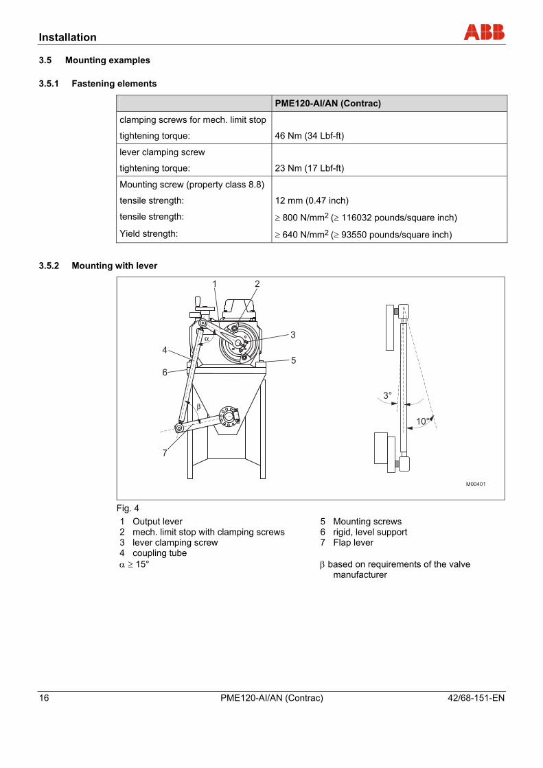
3.5.2 Mounting with lever
Fig. 4 1 Output lever 2 mech. limit stop with clamping screws 3 lever clamping screw 4 coupling tube α ≥ 15°
5 Mounting screws 6 rigid, level support 7 Flap lever β based on requirements of the valve
manufacturer
Pos: 8.26 /======= Seitenumbruch ======== @ 0\mod_1126532365768_3101.doc @ 3830

Installation
42/68-151-EN PME120-AI/AN (Contrac) 17
Pos: 8.27 /Überschriften/1.1.1/1-spaltig/Hebeltrieb PME120-AI/-AN @ 18\mod_1204708407968_3101.doc @ 167402
3.5.3 Lever PME120-AI/-AN Pos: 8.28 /Technische Daten / Datenblatt/Aktorik/Antriebe/Schwenkantriebe/El. Schwenkantrieb PME120-AI/-AN (Contrac)/Maßbild Hebeltrieb, Maße in mm / inch @ 5\mod_1151314497046_3101.doc @ 31996
201
19
32
48
28
32 150
100
125
8 45°
27
-0,0
15-0
,051
+0,2
18
14
61
15
62
...
78
14
24
60
46
18
19
46
1
2
3
21
+0
.02
7
0 0 -0,0
43
L-
14
0
L
M00067
9
24
+0
,03
3
0
62
...
78
Fig. 5: Dimensions in mm 1 Connection pipe 3/4” DIN 2440 resp. 3/4” schedule 40 pipe size
“L” acc. to requirements. The pipe is not included in shipment. 2 Cone 1 : 10
3 Angular deflection of ball and socket joint: Pointing towards the actuator: max. 3° Pointing away from the actuator: max. 10°
Installation
18 PME120-AI/AN (Contrac) 42/68-151-EN
7.91
0.7
5
1.2
6
1.8
9
1.1
0
1.26 5.91
3.94
4.92
0.31 45°
1.06
0.00
060.
002
0.008
0.71
0.55
2.40
0.59
2.4
4..
.3
.07
0.5
5
0.9
5
2.36
1.81
0.71
0.75
1.81
1
2
3
0.83
+0.0
01
0 0 -0.0
02
L-
5.5
1
L
M00067
0.35
0.9
5+
0.0
013
0
2.4
4..
.3
.07
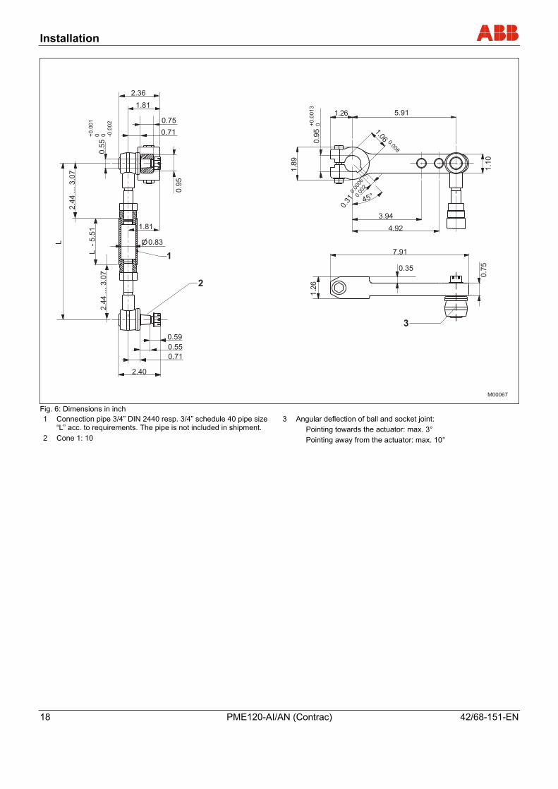
Fig. 6: Dimensions in inch 1 Connection pipe 3/4” DIN 2440 resp. 3/4” schedule 40 pipe size
“L” acc. to requirements. The pipe is not included in shipment. 2 Cone 1: 10
3 Angular deflection of ball and socket joint: Pointing towards the actuator: max. 3° Pointing away from the actuator: max. 10°
Pos: 8.29 /======= Seitenumbruch ======== @ 0\mod_1126532365768_3101.doc @ 3830
Installation
42/68-151-EN PME120-AI/AN (Contrac) 19
Pos: 8.30 /Überschriften/1.1.1/1-spaltig/Direktadapter PME120-AI/-AN @ 18\mod_1205933869828_3101.doc @ 171504
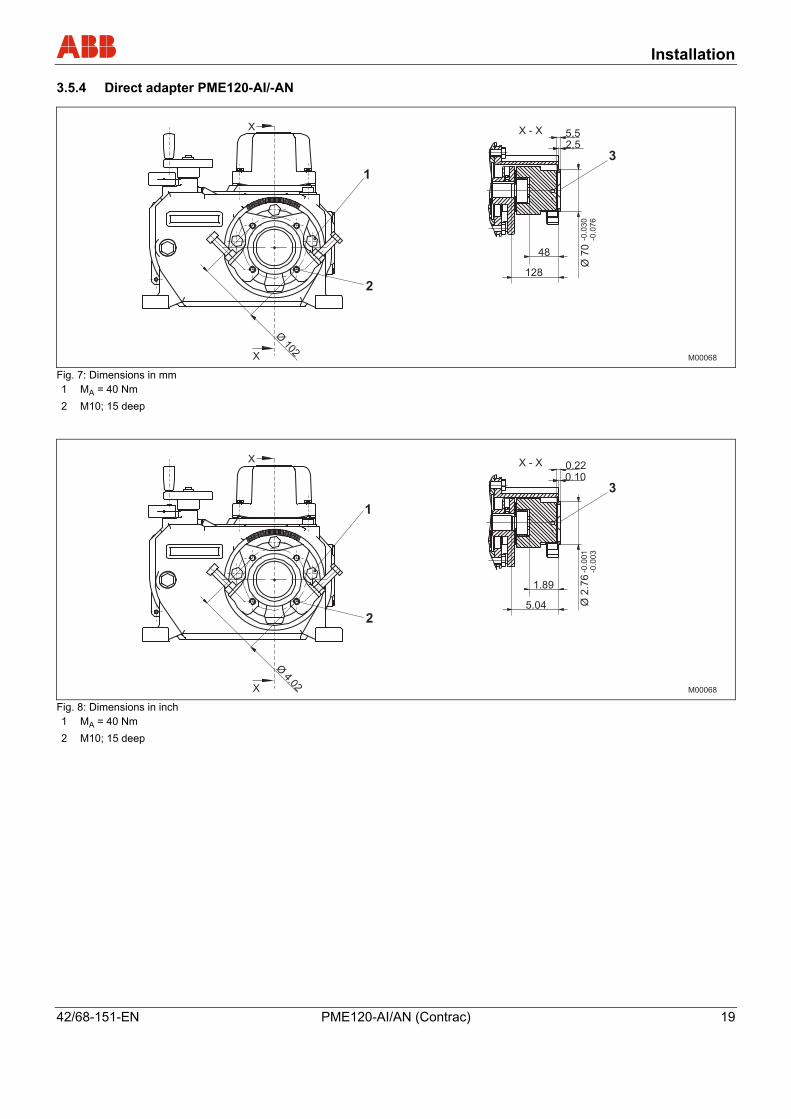
3.5.4 Direct adapter PME120-AI/-AN Pos: 8.31 /Technische Daten / Datenblatt/Aktorik/Antriebe/Schwenkantriebe/El. Schwenkantrieb PME120-AI/-AN (Contrac)/Maßbild Direktadapter, Maße in mm / inch @ 5\mod_1151314749140_3101.doc @ 32017
Fig. 7: Dimensions in mm 1 MA = 40 Nm 2 M10; 15 deep
Fig. 8: Dimensions in inch 1 MA = 40 Nm 2 M10; 15 deep
Pos: 9 /======= Seitenumbruch ======== @ 0\mod_1126532365768_3101.doc @ 3830

Electrical connection
20 PME120-AI/AN (Contrac) 42/68-151-EN
Pos: 10.1 /Überschriften/1/D - F/Elektrischer Anschluss @ 0\mod_1140620471687_3101.doc @ 3143
4 Electrical connection Pos: 10.2 /Elektrischer Anschluss/Aktorik/Allgemein/Elektrischer Anschluss @ 16\mod_1197274093609_3101.doc @ 145053
Each actuator requires a Contrac electronic unit which is loaded with the type specific-software. Carefully consider the instructions for the electronic unit and compare the data labels of the actuator and the electronic unit in order to ensure a proper hard- and software assignment.
Pos: 10.3 /Überschriften/1.1/1-spaltig/J - L/Kabelschirm @ 10\mod_1181823716656_3101.doc @ 106187
4.1 Cable shield Pos: 10.4 /Überschriften/1.1.1/1-spaltig/Signalteil @ 10\mod_1182501083765_3101.doc @ 108573
4.1.1 Signal part Pos: 10.5 /Elektrischer Anschluss/Aktorik/Antriebe/Allgemein/Kabelschirm Anschluss @ 10\mod_1181823021906_3101.doc @ 106144
Fig. 9: Fitting the shield
1. Remove approx. 2 cm of cable sheathing (3) from the end of the cable.
2. Separate the shield and peel it back to its inner sheathing (4).
3. Push the cable through the cable gland and fasten with clamp (1).
4. Make sure that the shielding is touching the clamp and the electronic unit housing (2).
Pos: 10.6 /======= Seitenumbruch ======== @ 0\mod_1126532365768_3101.doc @ 3830
Electrical connection
42/68-151-EN PME120-AI/AN (Contrac) 21
Pos: 10.7 /Überschriften/1.1/1-spaltig/G - I/Integrierte Elektronik AI (Standard) @ 18\mod_1205756489296_3101.doc @ 170446
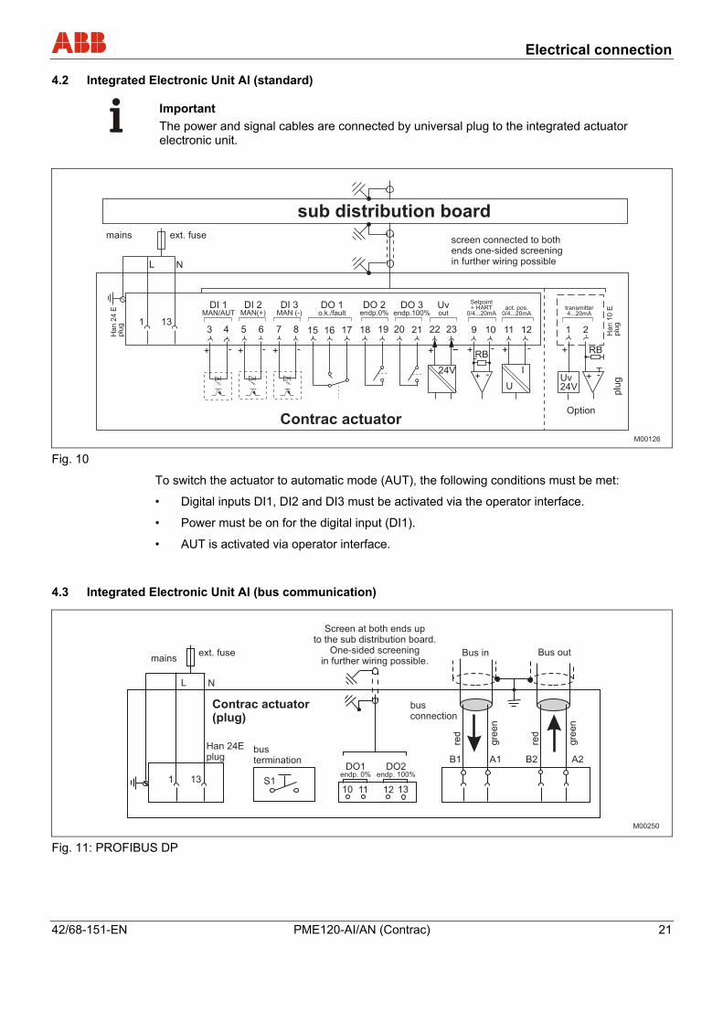
4.2 Integrated Electronic Unit AI (standard) Pos: 10.8 /Elektrischer Anschluss/Aktorik/Antriebe/Allgemein/Integrierte Elektronik AI Standard @ 18\mod_1205157040718_3101.doc @ 168891
Important The power and signal cables are connected by universal plug to the integrated actuator electronic unit.
Fig. 10
To switch the actuator to automatic mode (AUT), the following conditions must be met:
• Digital inputs DI1, DI2 and DI3 must be activated via the operator interface.
• Power must be on for the digital input (DI1).
• AUT is activated via operator interface.
Pos: 10.9 /Überschriften/1.1/1-spaltig/G - I/Integrierte Elektronik AI (Buskommunikation) @ 18\mod_1205756593250_3101.doc @ 170789
4.3 Integrated Electronic Unit AI (bus communication) Pos: 10.10 /Elektrischer Anschluss/Aktorik/Antriebe/Allgemein/Integrierte Elektronik AI Buskommunikation @ 18\mod_1205157289625_3101.doc @ 168914
Fig. 11: PROFIBUS DP
Pos: 10.11 /======= Seitenumbruch ======== @ 0\mod_1126532365768_3101.doc @ 3830

Electrical connection
22 PME120-AI/AN (Contrac) 42/68-151-EN
Pos: 10.12 /Überschriften/1.1/1-spaltig/D - F/Elektronik im Feldgehäuse EAN823 (Standard) @ 18\mod_1205756762171_3101.doc @ 170812
4.4 Electronic unit in field mount EAN823 (standard) Pos: 10.13 /Elektrischer Anschluss/Aktorik/Antriebe/Allgemein/Elektronik im Feldgehäuse EAN823 (Standard) @ 18\mod_1205157429109_3101.doc @ 168937
Important The electrical connection is provided by a plug on the actuator and the terminals on the electronic unit.
Fig. 12
To switch the actuator to automatic mode (AUT), the following conditions must be met:
• Digital inputs DI1, DI2 and DI3 must be activated via the operator interface.
• Power must be on for the digital input (DI1).
• AUT is activated via operator interface.
Pos: 10.14 /======= Seitenumbruch ======== @ 0\mod_1126532365768_3101.doc @ 3830

Electrical connection
42/68-151-EN PME120-AI/AN (Contrac) 23
Pos: 10.15 /Überschriften/1.1/1-spaltig/D - F/Elektronik im Feldgehäuse EAN823 (Buskommunikation) @ 18\mod_1205756885843_3101.doc @ 170835
4.5 Electronic unit in field mount EAN823 (bus communication) Pos: 10.16 /Elektrischer Anschluss/Aktorik/Antriebe/Allgemein/Elektronik im Feldgehäuse EAN823 (Buskommunikation) @ 18\mod_1205750350531_3101.doc @ 170423
Fig. 13: PROFIBUS DP
Pos: 10.17 /Überschriften/1.1/1-spaltig/J - L/Konfiguration der Binärsignal Ein- / Ausgänge (konventionelle Ansteuerung) @ 16\mod_1197966111421_3101.doc @ 146015
4.6 Configuration of digital input/output signals (standard control) Pos: 10.18 /Elektrischer Anschluss/Aktorik/Antriebe/Allgemein/Signal bei konventioneller Ansteuerung @ 18\mod_1205157717515_3101.doc @ 168960
4.6.1 Standard
Fig. 14: Potential wiring for default assignments

Electrical connection
24 PME120-AI/AN (Contrac) 42/68-151-EN
4.6.2 Downstream from step controller
Fig. 15: Potential wiring for "Downstream from step controller" operation
Important When operating the unit downstream from a step controller, the selector switch must be in the
position.
Important When DI1 is assigned with DC +24 V, the electronic unit is write-protected.
Pos: 11 /======= Seitenumbruch ======== @ 0\mod_1126532365768_3101.doc @ 3830

Local operation
42/68-151-EN PME120-AI/AN (Contrac) 25
Pos: 12.1 /Überschriften/1/J - L/Lokale Bedienung @ 1\mod_1144311291828_3101.doc @ 5751
5 Local operation Pos: 12.2 /Überschriften/1.1/1-spaltig/A - C/Allgemeine Informationen zur Bedienung @ 7\mod_1167724521984_3101.doc @ 53616
5.1 General information on operation Pos: 12.3 /Konfiguration, Parametrierung/Aktorik/Allgemein/Lokale Bedienung/Allgemeine Informationen zur Bedienung @ 7\mod_1166523369281_3101.doc @ 53108
The basic settings "Define end positions" and "Initial diagnosis" can be configured via the commissioning and service field (ISF). It can be used to adjust the actuator to the working area and set the direction without using a PC. The actuator can be further parametrized using a graphic user interface.
Important
The commissioning and service field is located on the electronic unit.
Pos: 12.4 /======= Seitenumbruch ======== @ 0\mod_1126532365768_3101.doc @ 3830
Local operation
26 PME120-AI/AN (Contrac) 42/68-151-EN
Pos: 12.5 /Überschriften/1.1/1-spaltig/A - C/Bedienelemente des Servicefelds (ISF) @ 7\mod_1167724580593_3101.doc @ 53637
5.2 Operating elements of the service field (ISF) Pos: 12.6 /Konfiguration, Parametrierung/Aktorik/Antriebe/Leistungselektroniken/Allgemein/Bedienelemente des Servicefelds (ISF) EX @ 13\mod_1191933980187_3101.doc @ 129109
1
2
3
4
5
67
8
9
10
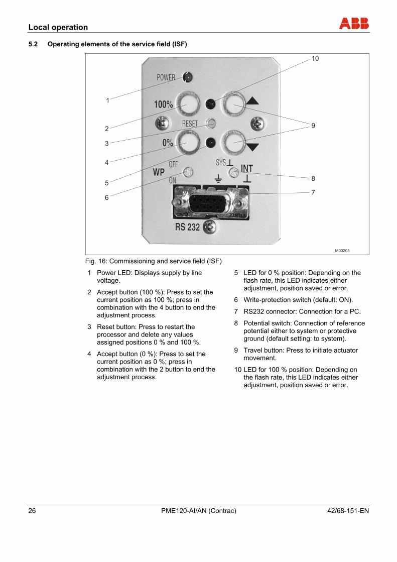
M00203 Fig. 16: Commissioning and service field (ISF)
1 Power LED: Displays supply by line voltage.
2 Accept button (100 %): Press to set the current position as 100 %; press in combination with the 4 button to end the adjustment process.
3 Reset button: Press to restart the processor and delete any values assigned positions 0 % and 100 %.
4 Accept button (0 %): Press to set the current position as 0 %; press in combination with the 2 button to end the adjustment process.
5 LED for 0 % position: Depending on the flash rate, this LED indicates either adjustment, position saved or error.
6 Write-protection switch (default: ON).
7 RS232 connector: Connection for a PC.
8 Potential switch: Connection of reference potential either to system or protective ground (default setting: to system).
9 Travel button: Press to initiate actuator movement.
10 LED for 100 % position: Depending on the flash rate, this LED indicates either adjustment, position saved or error.
Pos: 13.1 /Überschriften/1/G - I/Inbetriebnahme und Servicefeld (ISF) @ 5\mod_1167725076390_3101.doc @ 53680

Commissioning and service field (ISF)
42/68-151-EN PME120-AI/AN (Contrac) 27
6 Commissioning and service field (ISF) Pos: 13.2 /Überschriften/1.1/1-spaltig/S - U/Typische Inbetriebnahme mit dem Servicefeld (ISF) @ 7\mod_1167725302531_3101.doc @ 53720
6.1 Typical commissioning with the service field (ISF) Pos: 13.3 /Konfiguration, Parametrierung/Aktorik/Antriebe/Leistungselektroniken/EAN823,EBN853,EBN861/Typische Inbetriebnahme mit dem Servicefeld (ISF) EX @ 16\mod_1197968117187_3101.doc @ 146160
Important
The operating range of the actuator is not adjusted at time of delivery.
For information on setting up the mechanical end stops, refer to the operating instructions of the relevant actuator.
Part of the commissioning activities below can only be performed by opening the cover flap of the ISF.
6.1.1 Status
• The electronic unit is connected to the power supply and wired to the actuator.
• The electronic unit is in the MAN operating mode; no signal at digital input 1 (DI 1).
• No error (if an error exists, the LEDs flash alternately at 4 Hz).
6.1.2 Opening the cover flap of the ISF
• Release the screws for the cover flap.
• Swing the cover flap to the side.
6.1.3 Operating mode "Device setup"
• Switch the electronic unit to the "Device setup" operating mode. Press and hold both travel buttons (9) at once for approx. 5 s until both LEDs (items 5 and 10 in Fig. 16) flash in sync at a rate of 4 Hz.
6.1.4 Setup via user interface
Context-sensitive online Help can be called at any time via the graphical user interface.
Important The RS232 communication cable provides a conductive ground connection between the computer and the Contrac electronic unit. If the PC is grounded, a ground loop may form in the system.
Commissioning and service field (ISF)
28 PME120-AI/AN (Contrac) 42/68-151-EN
6.1.5 Defining the initial position (0 % or 100 %)
• Use a travel button (9) to move to the desired position.
• Press the Accept button (2) or (4) to accept the position; if successful, the corresponding LED flashes at a rate of 1 Hz. The other LED continues to flash at approx. 4 Hz.
6.1.6 Defining the second position (0 % or 100 %)
• Use a button (9) to move to the second position.
• To accept the position, press the Accept button (2) or (4). If successful, both LEDs(5) and (10) flash at a rate of approx. 1 Hz.
6.1.7 Saving your settings
• Press both Accept buttons (2 + 4) to accept the settings. The LEDs (5 + 10) stop flashing after a short period of time and the adjustment process is completed.
• If the range selected for the actuator is too small, both LEDs begin to flash again at 4 Hz and the setup procedure must be repeated with a larger value (min. actuator travel).
(Information regarding actuator travel on the model plate)

Commissioning and service field (ISF)
42/68-151-EN PME120-AI/AN (Contrac) 29
6.1.8 Correcting settings
• If after accepting the initial value for the settings you need to correct this value, press the reset button (3) and repeat the settings.
• If you need to make corrections after saving, the complete setup procedure must be performed again.
6.1.9 Signals on the commissioning and service field (ISF)
Function Signals
Device Setup
Switch to Device Setup: Press and hold both travel buttons for approx. 5 s.
Both LEDs then flash in sync at 4 Hz.
Reaching an end position: Use the appropriate button on the ISF.
Both LEDs continue to flash at 4 Hz during actuator travel.
Save the initial end position: Press 0 % or 100 %.
The corresponding LED flashes at approx. 1 Hz, the others continue to flash at 4 Hz.
Save the second end position: Press 0 % or 100 %.
The related LED flashes at approx. 1 Hz in sync with the first LED.
Finish Adjustment: Press 0 % and 100 % at once.
Both LEDs light up briefly and then stop flashing.
Operation
Standard operation: MAN / AUT The LEDs are switched off.
Positioning via the button on the ISF takes priority over the control system.
The LEDs are switched off.
Error (both LEDs flash alternately at 4 Hz)
Reset: Resets error messages. If no other error exists, both LEDs stop flashing.
Reset if the operating range is overshot: Hold both travel buttons for 5 s and then press the Reset button.
After approx. 5 s, the flashing is briefly interrupted. After a reset, the electronic unit will be in adjustment mode.
Important
After startup, it is recommended that you use the control system to operate the actuator and check the behavior as well as signaling of the actuator.
To place the actuator in automatic mode after startup, a 24 V DC signal at the digital input 1 must be present for actuators with active digital input functions (default setting).
If the digital function is switched off, the actuator switches to automatic mode immediately after completing the adjustment process.
Pos: 13.4 /======= Seitenumbruch ======== @ 0\mod_1126532365768_3101.doc @ 3830
Commissioning and service field (ISF)
30 PME120-AI/AN (Contrac) 42/68-151-EN
Pos: 13.5 /Überschriften/1.1/1-spaltig/P - R/Positionen des Potenzialumschalters @ 16\mod_1197986226843_3101.doc @ 146548
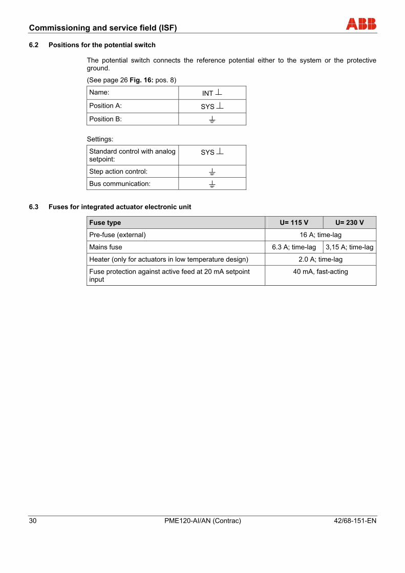
6.2 Positions for the potential switch Pos: 13.6 /Konfiguration, Parametrierung/Aktorik/Antriebe/Leistungselektroniken/EAN823,EBN853,EBN861/Positionen des Potenzialumschalters @ 16\mod_1197986081890_3101.doc @ 146525
The potential switch connects the reference potential either to the system or the protective ground.
(See page 26 Fig. 16: pos. 8)
Name: INT
Position A: SYS
Position B: Settings:
Standard control with analog setpoint:
SYS
Step action control: Bus communication:
Pos: 13.7 /Überschriften/1.1/1-spaltig/S - U/Sicherungen bei integrierter Antriebselektronik @ 18\mod_1205932178718_3101.doc @ 171434
6.3 Fuses for integrated actuator electronic unit Pos: 13.8 /Elektrischer Anschluss/Aktorik/Antriebe/Allgemein/Sicherungen bei integrierter Antriebselektronik @ 18\mod_1205157894953_3101.doc @ 168983
Fuse type U= 115 V U= 230 V
Pre-fuse (external) 16 A; time-lag
Mains fuse 6.3 A; time-lag 3,15 A; time-lag
Heater (only for actuators in low temperature design) 2.0 A; time-lag
Fuse protection against active feed at 20 mA setpoint input
40 mA, fast-acting
Pos: 13.9 /======= Seitenumbruch ======== @ 0\mod_1126532365768_3101.doc @ 3830
Commissioning and service field (ISF)
42/68-151-EN PME120-AI/AN (Contrac) 31
Pos: 13.10 /Konfiguration, Parametrierung/Aktorik/Antriebe/Contrac/PME120/Einbauorte der Sicherungen @ 18\mod_1205932847000_3101.doc @ 171457
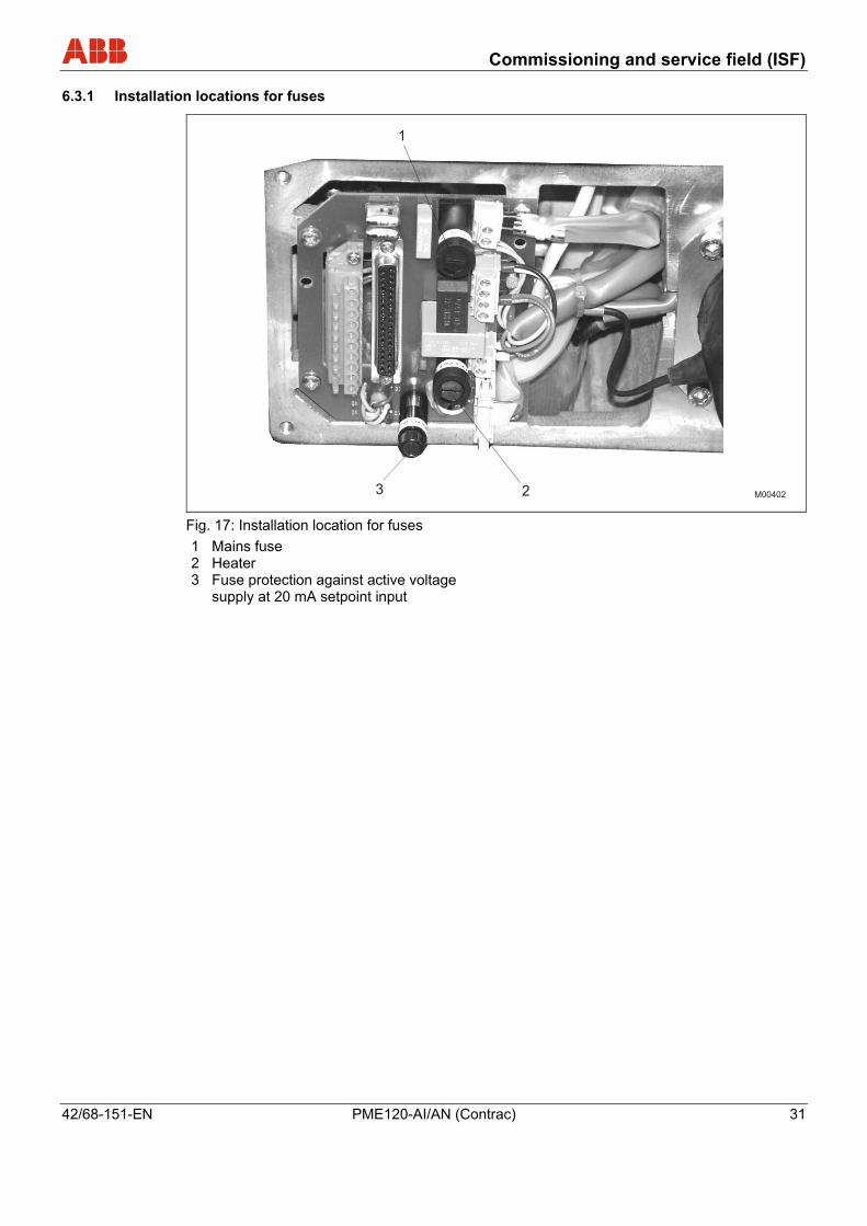
6.3.1 Installation locations for fuses
Fig. 17: Installation location for fuses 1 Mains fuse 2 Heater 3 Fuse protection against active voltage
supply at 20 mA setpoint input
Pos: 14 /======= Seitenumbruch ======== @ 0\mod_1126532365768_3101.doc @ 3830

Operation
32 PME120-AI/AN (Contrac) 42/68-151-EN
Pos: 15 /======= Seitenumbruch ======== @ 0\mod_1126532365768_3101.doc @ 3830 Pos: 16.1 /Überschriften/1/A - C/Betrieb @ 10\mod_1175678278921_3101.doc @ 76015
7 Operation Pos: 16.2 /Überschriften/1.1/1-spaltig/A - C/Automatik / Handbetrieb @ 10\mod_1181715570281_3101.doc @ 104973
7.1 Automatic / manual mode Pos: 16.3 /Bedienung/Aktorik/Antriebe/Schwenkantriebe/Allgemein/Automatik / Handbetrieb @ 10\mod_1181715898015_3101.doc @ 105066
The motor triggered by the power electronics controls the drive shaft via oil-lubricated spur gears. This transmits the torque to the valve via a lever with ball-and-socket joints and a coupling rod. A position sensor detects backlash-free the current position of the drive shaft.
Adjustable limit stops prevent overloading of the valve in the event of an operating error. The motor brake locks the actuator in the current position if the power suplly is cut off.
Pos: 16.4 /Überschriften/1.1/1-spaltig/G - I/Handradbetrieb @ 10\mod_1181715640046_3101.doc @ 104996
7.2 Manual operation Pos: 16.5 /Bedienung/Aktorik/Antriebe/Schwenkantriebe/PME120/Handradbetrieb @ 18\mod_1205933445031_3101.doc @ 171481
Manual mode allows you to move the actuator manually when the electrical power is off.
Caution - Risk of injury! When pressing the release lever, the restoring force from the valve may be present in the hand wheel. To prevent the hand wheel from turning unintentionally, hold the hand wheel with one hand.
1. Press the release lever.
2. Turn the hand wheel to move the part-turn actuator to the desired position.
3. Let go of the release lever.
Pos: 17 /======= Seitenumbruch ======== @ 0\mod_1126532365768_3101.doc @ 3830
Maintenance
42/68-151-EN PME120-AI/AN (Contrac) 33
Pos: 18.1 /Überschriften/1/V - Z/Wartung @ 10\mod_1181642125390_3101.doc @ 103817
8 Maintenance Pos: 18.2 /Wartung / Reparatur/Aktorik/Antriebe/Allgemein/Wartung @ 10\mod_1181640290218_3101.doc @ 103695
Important All maintenance activities may only be performed by properly qualified persons.
Contrac actuators feature a robust construction. As a result, they are highly reliable and require minimal maintenance. The maintenance intervals depend upon the effective load and are therefore not specified here.
The built-in microprocessor evaluates the actual load factors (e.g. torques, forces, temperatures, etc.) and derives the remaining operating time until the next routine maintenance is required.
Use the configuration program to view this information.
Pos: 18.3 /Überschriften/1.1/1-spaltig/G - I/Inspektion und Überholung @ 10\mod_1181642170921_3101.doc @ 103840
8.1 Inspection and overhaul Pos: 18.4 /Wartung / Reparatur/Aktorik/Antriebe/Allgemein/Inspektion und Überholung @ 16\mod_1197275309500_3101.doc @ 145205
• Only use genuine spare parts such as ball bearings, gaskets and oil may be used to overhaul the actuators.
• Proceed acc. to table when performing maintenance activities.
• Inspection or maintenance is due after the time specified in the table.
Overhaul intervals:
Interval Measures
1 x per year Visual check of the gaskets for leaks, change if necessary.
Change oil, roller bearings and gaskets on motor and gearing.
max. every 10 years, preferably after the expiry of the calculated remaining service life
Check gear wheels for wear; replace if necessary.
Don’t drive the actuator during the oil check.
Make sure that no chippings or other material get into the gearbox during the maintenance work.
Pos: 18.5 /======= Seitenumbruch ======== @ 0\mod_1126532365768_3101.doc @ 3830

Maintenance
34 PME120-AI/AN (Contrac) 42/68-151-EN
Pos: 18.6 /Überschriften/1.1/1-spaltig/A - C/Bremseneinstellung @ 10\mod_1181642242218_3101.doc @ 103863
8.2 Brake adjustment Pos: 18.7 /Wartung / Reparatur/Aktorik/Antriebe/Elektr. Schwenkantriebe/Allgemein/Bremseneinstellung @ 18\mod_1204698670531_3101.doc @ 167013
Warning - risk of injury! Note that the actuator position may be changed accidentally by the repelling power of the valve when the brake is released! Make sure that process forces are not exerted on the lever.
Since the brake is permanently released in AUT mode it is not exposed to mechanical wear. Any readjustment is not necessary. Enables users to test the configuration software of the brake.
Pos: 18.8 /Überschriften/1.1/1-spaltig/M - O/Ölwechsel @ 10\mod_1181652527843_3101.doc @ 104243
8.3 Oil change Pos: 18.9 /Wartung / Reparatur/Aktorik/Antriebe/Allgemein/Ölwechsel @ 10\mod_1181632020265_3101.doc @ 103369
Important Oils for different temperature ranges may not mixed. Dispose of old oil according to local regulations. Make sure that the oil does not enter the water cycle.
Proceed as follows to drain or change the oil:
1. Provide a container capable of holding the expected oil quantity acc. to chapter „Filling capacity“.
2. Open and remove the ventilation plug, see Fig. 3.
3. Unscrew the lowermost inspection plug and drain the oil.
4. Make sure all the oil is out of the actuator.
5. Screw in and tighten the oil drain plug.
6. Fill the container with the proper volume of oil and tighten the venting plug.
Pos: 18.10 /Wartung / Reparatur/Aktorik/Antriebe/Elektr. Schwenkantriebe/PME120/Schmiermittel @ 18\mod_1204808253515_3101.doc @ 167506
Ambient temp. Actuator type
with heat without heat Type of
oil Motor mounting
(grease)
PME 120 AI
(with integrated electronic unit)
-25 ... 55 °C (-15 ... 130 °F)
-10 ... 55 °C (15 ... 130 °F)
PME 120 AN
(for separate electronic unit)
-25 ... 65 °C (-15 ... 150 °F)
-10 ... 65 °C (15 ... 150 °F)
Mobil
SHC 629 ESSO Beacon 325
Pos: 18.11 /Überschriften/1.1/1-spaltig/D - F/Füllmengen @ 10\mod_1181654885484_3101.doc @ 104359
8.4 Filling capacity Pos: 18.12 /Wartung / Reparatur/Aktorik/Antriebe/Elektr. Schwenkantriebe/PME120/Füllmengen @ 18\mod_1204810073562_3101.doc @ 167759
Filling capacity for PME120-AI/-AN Mounting orientation IMB 3 IMB 6 IMB 7 IMB 8 IMV 5 IMV 6
Minimum oil quantity, approx.:
2,2 l (0,58 gal.1))
2,5 l (0,66 gal.1))
2,2 l (0,58 gal.1))
2,2 l (0,58 gal.1))
2,5 l (0,66 gal.1))
2,5 l (0,66 gal.1))
Min. oil level [mm] under
inspection plug:
45 mm (1.77 inch)
2 mm (0.08 inch)
42 mm (1.65 inch)
20 mm
(0.79 inch)
23 mm
(0.91 inch)
17 mm
(0.67 inch)
1) US liquid gallon Pos: 19 /======= Seitenumbruch ======== @ 0\mod_1126532365768_3101.doc @ 3830
Alarms / Errors
42/68-151-EN PME120-AI/AN (Contrac) 35
Pos: 20.1 /Überschriften/1/A - C/Alarme / Fehler @ 13\mod_1191918058984_3101.doc @ 128661
9 Alarms / Errors Pos: 20.2 /Überschriften/1.1/1-spaltig/D - F/Definition @ 13\mod_1191918133734_3101.doc @ 128707
9.1 Definition Pos: 20.3 /Fehlermeldungen/Allgemein/Alarme @ 13\mod_1191907921656_3101.doc @ 128299
9.1.1 Alarms
The actuator or electronic unit is in a critical state (e.g., high temperature), which currently does not affect the actuator, electronic unit, process or persons. The actuator functions are available. Previous alarms are stored in the "Saved Alarms" area in the electronic unit. The graphic user interface use to output the stored alarms.
Pos: 20.4 /Fehlermeldungen/Allgemein/Fehler @ 13\mod_1191908411312_3101.doc @ 128322
9.1.2 Error
The actuator or electronic unit is in a critical state, e.g., positioning time-out, which currently is impairing the actuator, electronic unit, process or persons. The actuator is switched off and the actuator functions are no longer available. Previous error messages are stored in the "Saved Errors" area in the electronic unit. Use the graphic user interface to output the stored errors. Error messages cannot be reset until the cause of the error has been eliminated.
Pos: 20.5 /======= Seitenumbruch ======== @ 0\mod_1126532365768_3101.doc @ 3830

Alarms / Errors
36 PME120-AI/AN (Contrac) 42/68-151-EN
Pos: 20.6 /Überschriften/1.1/1-spaltig/A - C/Alarm Schema @ 13\mod_1191918181968_3101.doc @ 128730
9.2 Alarm diagram Pos: 20.7 /Fehlermeldungen/Allgemein/Alarm Schema @ 13\mod_1191909106750_3101.doc @ 128345
Setpoint time-out Transmitter monitoring
Maintenance Actuator temperature
Temperature of Electronic Unit
upper limit/ lower limit upper limit/ lower limit
Lubricant / Elastom. Motor / Gear
(high / low) (high / low)
Monitoring ON Integr. controller ON
Behavior at critical temp. MAN AUT
& & & &
Actuator Stop Safety pos. last setpoint
Actuator moves in desired operating mode
Alarm Signal
Saved Alarms (Reset Option)
General Alarm Display ON
Pos: 20.8 /======= Seitenumbruch ======== @ 0\mod_1126532365768_3101.doc @ 3830
Alarms / Errors
42/68-151-EN PME120-AI/AN (Contrac) 37
Pos: 20.9 /Überschriften/1.1/1-spaltig/D - F/Fehler Schema @ 13\mod_1191918225828_3101.doc @ 128753
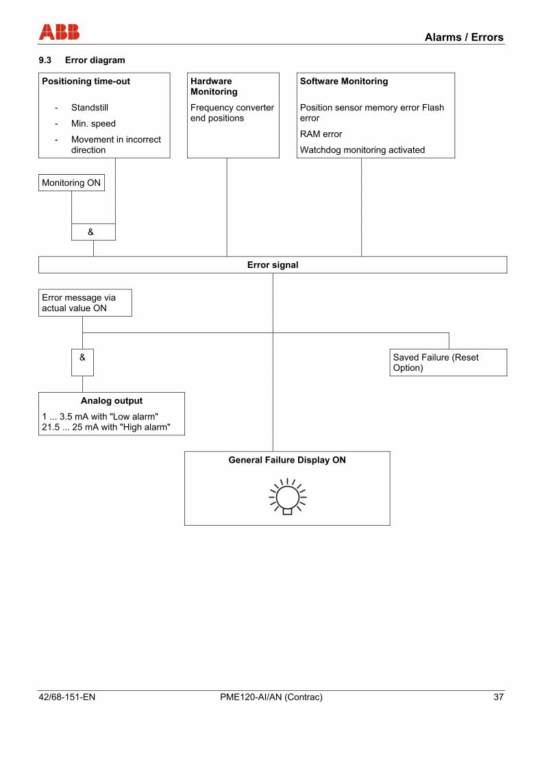
9.3 Error diagram Pos: 20.10 /Fehlermeldungen/Allgemein/Fehler Schema @ 13\mod_1191916378062_3101.doc @ 128588
Positioning time-out Hardware Monitoring
Software Monitoring
- Standstill
- Min. speed
- Movement in incorrect direction
Frequency converter end positions
Position sensor memory error Flash error
RAM error
Watchdog monitoring activated
Monitoring ON
&
Error signal
Error message via actual value ON
& Saved Failure (Reset Option)
Analog output
1 ... 3.5 mA with "Low alarm" 21.5 ... 25 mA with "High alarm"
General Failure Display ON
Pos: 20.11 /======= Seitenumbruch ======== @ 0\mod_1126532365768_3101.doc @ 3830

Trouble shooting
38 PME120-AI/AN (Contrac) 42/68-151-EN
Pos: 20.12 /Überschriften/1/D - F/Fehlerbehebung @ 8\mod_1177421457781_3101.doc @ 86174
10 Trouble shooting Pos: 20.13 /Fehlermeldungen/Aktorik/Antriebe/Allgemein/Fehlersuche @ 20\mod_1209118101843_3101.doc @ 182650
This chapter only covers hardware-related errors. For additional troubleshooting information, refer to the online help for the operator interface.
Error Possible cause Troubleshooting Valve cannot be moved by actuator.
Failure either on the actuator or the valve (e.g., stuffing box tightened too much).
Disconnect actuator from valve. If the actuator moves, the valve is the possible cause. If the actuator does not move, the actuator is the possible cause.
Incorrect electronic unit or incorrect data record.
Compare information on name plates for actuator and electronic unit.
Incorrectly configured electronic unit.
Check/update the settings for the parametrization software.
No communication with the control system.
Check wiring.
Incorrect wiring between actuator and electronic unit.
Check wiring.
Defective motor/brake. Check the winding resistance of the motor and brake. Check the brake lock.
Binary inputs on the electronic unit are not wired.
Make connection.
The actuator does not respond.
Brake does not release (no mechanical "click").
Check the brake air gap (approx. 0.25 mm (0.010 inch)) and electrical connection to the brake. Check winding resistance of the brake coil.
Actuator does not run in AUT mode, although “AUT” is selected in the user interface.
Digital input 1 (DI 1) not wired.
Make connection. Check the software settings for the digital inputs.
LEDs in the commissioning and service panel (CSP) flash synchronously.
Actuator is not adjusted properly.
Adjust actuator.
LEDs flash alternately. Electronic unit / drive malfunction.
Malfunction when approaching the end position.
Actuator in limit range of positioning sensor.
Drive the actuator beyond the adjusted end position (either manually or using the pushbuttons on the CSP). Disconnect from valve, if necessary. Drive the actuator back into the operating range and connect it to the valve. Readjust the actuator for the operating range.
Pos: 20.14 /======= Seitenumbruch ======== @ 0\mod_1126532365768_3101.doc @ 3830
Trouble shooting
42/68-151-EN PME120-AI/AN (Contrac) 39
Pos: 20.15 /Überschriften/1.1/1-spaltig/D - F/Elektrische Prüfwerte @ 10\mod_1181642679500_3101.doc @ 103909
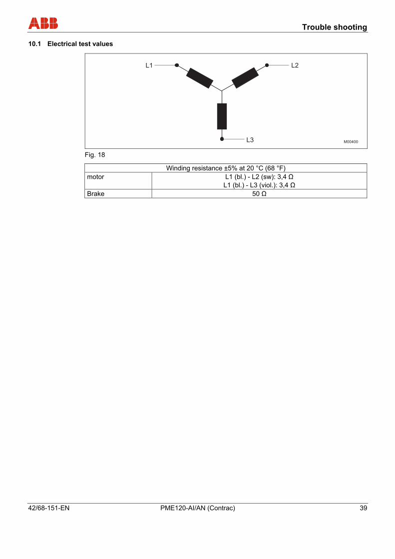
10.1 Electrical test values Pos: 20.16 /Fehlermeldungen/Aktorik/Antriebe/Allgemein/Elektrische Prüfwerte @ 18\mod_1204794223640_3101.doc @ 167483
Fig. 18
Winding resistance ±5% at 20 °C (68 °F) motor L1 (bl.) - L2 (sw): 3,4 Ω
L1 (bl.) - L3 (viol.): 3,4 Ω Brake 50 Ω
Pos: 21 /======= Seitenumbruch ======== @ 0\mod_1126532365768_3101.doc @ 3830

Technical data
40 PME120-AI/AN (Contrac) 42/68-151-EN
Pos: 22.1 /Überschriften/1/S - U/Technische Daten @ 0\mod_1132904574837_3101.doc @ 3169
11 Technical data Pos: 22.2 /Überschriften/1.1/1-spaltig/A - C/Allgemeine Daten @ 0\mod_1140622753015_3101.doc @ 3177
11.1 General information Pos: 22.3 /Technische Daten / Datenblatt/Aktorik/Antriebe/Schwenkantriebe/El. Schwenkantrieb PME120-AI/-AN (Contrac)/Allgemeine Daten @ 5\mod_1151309430890_3101.doc @ 31660
PME120-AI (integrated electronic unit) PME120-AN (separate electronic unit) Operating mode S9 - 100 %; stall proof acc. to IEC 60034-1 / EN 60034-1 Protection class IP 66 Humidity ≤ 95 % average; condensation not permitted Ambient temperature -10 … 55 °C (15 … 130 °F)
-25 … 55 °C (-15 … 130 °F) -10 … 65 °C (15 … 150 °F) -25 … 55 °C (-15 … 130 °F) -1 … 85 °C (30 … 185 °F)
Mounting position any position; preferably IMB 3 acc. to IEC 60034-7 / EN 60034-7 Coating 2-layer component epoxy (RAL 9005; black) Anti-condensation heater - Optional, separate power supply or power feed from
Contrac electronic unit Power supply for motor and sensors
Only via Contrac electronic unit (refer to the data sheet for the electronic unit)
Cable between actuator and electronic unit
- Select from 5 m (16 ft), 10 m (32 ft) or 20 m (65 ft) max. 30 m (98 ft) for EAN823 electronic unit max. 480 m (1575 ft) for EAS822 electronic unit
(read the data sheet for the electronic unit) Weight, approx. 32 kg (70 lb) 36 kg (79 lb)
Pos: 22.4 /==== Wechsel ein- auf zweispaltig ==== @ 0\mod_1130421847171_3101.doc @ 3828 Wechsel ein-auf zweispaltig Pos: 22.5 /Technische Daten / Datenblatt/Aktorik/Antriebe/Schwenkantriebe/El. Schwenkantrieb PME120-AI/-AN (Contrac)/Regelantrieb @ 5\mod_1151306489265_3101.doc @ 31576
Model PME120-AN; PME120-AI Rated torque 100 Nm (80 lbf-ft), adjustable to 0.5; 0.75 or
1x rated torque Starting torque 1.2 x rated torque (break-away torque in end
positions for short time 2 x rated torque) Rated time for 90° (Operating speed)
Adjustable from 20 … 900 s (4.5 … 0.1°/s)
Operating angle Typically 90 ° (min. 35°; max. 270°), see manual for reduced angle with lever and limit stop
Associated electronic unit (data sheet)
PME120-AI: integrated electronic unit PME120-AN: Designed for field installation: EAN823 (10/68-8.26) Designed for rack installation: EAS822 (10/68-8.23)
Motor 24 V 3~ asynchronous motor for operation with electronic unit EAN823 or EAS822
Sensors Position and temperature sensor always available
Pos: 22.6 /==== Wechsel zwei- auf ein
spaltig ==== @ 0\mod_1130421955859_3101.doc @ 3829
Wechsel ein-auf zweispaltig Pos: 23 /======= Seitenumbruch ======== @ 0\mod_1126532365768_3101.doc @ 3830
Appendix
42/68-151-EN PME120-AI/AN (Contrac) 41
Pos: 24.1 /Überschriften/1/A - C/Anhang @ 0\mod_1132904773022_3101.doc @ 3134
12 Appendix Pos: 24.2 /Überschriften/1.1/1-spaltig/V - Z/Zulassungen und Zertifizierungen @ 0\mod_1132230068395_3101.doc @ 3806
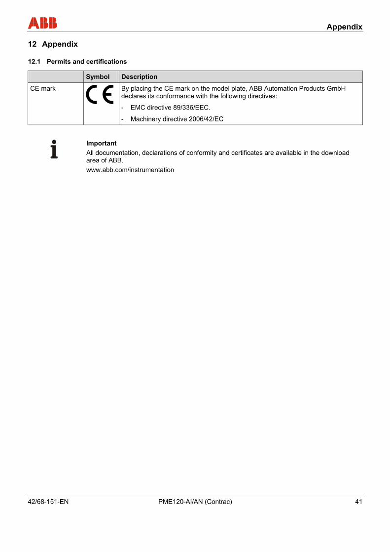
12.1 Permits and certifications Pos: 24.3 /Anhang/Allgemein/Zulassungen und Zertifizierungen (CE) @ 18\mod_1205231786867_3101.doc @ 169127 Zu
Symbol Description
CE mark
By placing the CE mark on the model plate, ABB Automation Products GmbH declares its conformance with the following directives:
- EMC directive 89/336/EEC.
- Machinery directive 2006/42/EC
Pos: 24.4 /Anhang/Allgemein/Hinweis zum Download-Bereich (Aktorik) @ 10\mod_1182172251781_3101.doc @ 107696
Important All documentation, declarations of conformity and certificates are available in the download area of ABB. www.abb.com/instrumentation
Pos: 24.5 /======= Seitenumbruch ======== @ 0\mod_1126532365768_3101.doc @ 3830

Appendix
42 PME120-AI/AN (Contrac) 42/68-151-EN
Pos: 24.6 /Anhang/Allgemein/Rücksendeformular @ 0\mod_1132757486454_3101.doc @ 3820
Statement about the contamination of devices and components
The repair and/or maintenance of devices and components will only be performed when a completely filled out explanation is present.
Otherwise, the shipment can be rejected. This explanation may only be filled out and signed by authorized specialist personnel of the operator.
Customer details:
Company:
Address:
Contact person: Telephone:
Fax: E-Mail:
Device details:
Type: Serial no.:
Reason for the return/description of the defect:
Was this device used for working with substances which pose a threat or health risk?
Yes No
If yes, which type of contamination (please place an X next to the applicable items)
biological corrosive/irritating combustible (highly/extremely combustible)
toxic explosive other harmful substances
radioactive
Which substances have had contact with the device?
1.
2.
3.
We hereby certify that the devices/parts shipped were cleaned and are free from any dangerous or poisonous materials.
City, Date Signature and company stamp
Pos: 25 /======= Seitenumbruch ======== @ 0\mod_1126532365768_3101.doc @ 3830
Index
42/68-151-EN PME120-AI/AN (Contrac) 43
Pos: 26.1 /Überschriften/1/G - I/Index @ 0\mod_1138787046328_3101.doc @ 3151
13 Index Pos: 26.2 /==== Wechsel ein- auf zweispaltig ==== @ 0\mod_1130421847171_3101.doc @ 3828 Wechsel ein-auf zweispaltig Pos: 26.3 /Inhaltsverzeichnis/Index @ 0\mod_1138784494500_3101.doc @ 3128
A
Actuator check .........................................................13
Actuator electronic unit ............................................22
Adjusting the stops for torque............................15, 16
Adjusting the stops for travel .............................15, 16
Alarm diagram..........................................................38
Alarms......................................................................37
Alarms / Errors .........................................................37
Appendix ..................................................................43
Assembly with the valve ..........................................14
AUT mode..........................................................22, 36
Automatic / manual mode ........................................34
B
Brake adjustment.....................................................36
C
Cable shield .............................................................21
CE mark ...................................................................43
Commissioning and service field (ISF) ....................27
Configuration of digital input/output signals (conventional control)...........................................24
Contrac electronic unit .............................................21
Correcting settings...................................................30
D
Default assignments ................................................24
Defining the initial position .......................................29
Defining the second position....................................29
Design and function .................................................12
Device setup ............................................................30
Direct adapter PME120-AI/-AN................................20
Disposal .....................................................................9
Downloads ...............................................................43
Downstream from step controller.............................25
E
Electrical connection................................................21
Electrical installation safety information...................11
Electronic unit in field mount EAN823 (bus communication) ....................................................24
Electronic unit in field mount EAN823 (standard)....23
EMC directive...........................................................43
Error .........................................................................37
Error diagram...........................................................39
F
Failure ......................................................................30
Filling capacities.......................................................36
Filling capacity .........................................................36
Fuses for integrated actuator electronic unit ...........31
G
General information .................................................42
General information on operation ............................26
General Safety Information........................................6
I
Inspection and overhaul...........................................35
Installation................................................................13
Installation instructions ............................................14
Installation locations for fuses..................................32
Installation position ..................................................36
Installation safety information ..................................10
Integrated Electronic Unit AI (bus communication) .22
Integrated Electronic Unit AI (standard)...................22
L
Labels and symbols ...................................................7
Lever PME120-AI/-AN .............................................18
Local operation ........................................................26
M
Maintenance ............................................................35
Maintenance activities .............................................35
Maintenance intervals..............................................35
Manual operation .....................................................34
Mounting position.....................................................13
N
Name plate.................................................................8
O
Oil change................................................................36
Opening the cover flap of the ISF ............................28
Operating elements of the service field (ISF) ..........27
Operating mode .......................................................28
Operating safety information....................................11

Index
44 PME120-AI/AN (Contrac) 42/68-151-EN
Operation .................................................................34
Operator liability .........................................................8
P
Permits and certifications.........................................43
Personnel qualification...............................................8
Positions for the potential switch .............................31
Preparation for mounting with direct adapter...........16
Preparation for mounting with lever .........................14
Process forces ...................................................11, 36
R
Repelling power .................................................11, 36
Returning devices ......................................................9
S
Safety.........................................................................6
Saving your settings ................................................29
Setup via user interface ...........................................28
Signals on the commissioning and service field (ISF).............................................................................30
Spur gearing ............................................................13
Status.......................................................................28
Storage conditions ...................................................10
Symbols and warnings...............................................7
T
Technical data..........................................................42
Technical limits ..........................................................6
tensile strength.........................................................17
tightening torque ......................................................17
Time until next maintenance is required..................35
Transport safety information ......................................9
Trouble shooting ......................................................40
Typical commissioning with the service field (ISF) ..27
W
Warranty provision.....................................................7
Wear ........................................................................35
WEEE directive ..........................................................9
Winding resistance...................................................41
Pos: 26.4 /==== Wechsel zwei- auf einspaltig ==== @ 0\mod_1130421955859_3101.doc @ 3829
Wechsel ein-auf zweispaltig Pos: 27 /Rückseiten/Minden_Aktorik @ 2\mod_1151575081640_3101.doc @ 32243 ===== Ende der Stückliste =====

ABB has Sales & Customer Support expertise in over 100 countries worldwide. www.abb.com/instrumentation
The Company’s policy is one of continuous productimprovement and the right is reserved to modify the
information contained herein without notice.
Printed in the Fed. Rep. of Germany (06.2008)
© ABB 2008
3KXE111005R4201
42/6
8-15
1-EN
R
ev. D
ABB Limited Salterbeck Trading Estate Workington, Cumbria CA14 5DS UK Tel: +44 (0)1946 830 611 Fax: +44 (0)1946 832 661
ABB Inc. 125 E. County Line Road Warminster, PA 18974 USA Tel: +1 215 674 6000 Fax: +1 215 674 7183
ABB Automation Products GmbH Schillerstr. 72 32425 Minden Germany Tel: +49 551 905-534 Fax: +49 551 905-555 [email protected]