operating instructions 8250 brake unit - lenzedownload.lenze.com/td/8250__brake...
TRANSCRIPT
EDB8250EN!PM8
Operating Instructions
Brake unit8250 series
Ä!PM8ä
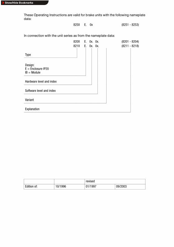
These Operating Instructions are valid for brake units with the following nameplatedata:
825X E. 0x (8251 - 8253)
In connection with the unit series as from the nameplate data:
820X E. 0x. 0x. (8201 - 8204)821X E. 0x. 0x. (8211 - 8218)
Type
Design:E = Enclosure IP20IB = Module
Hardware level and index
Software level and index
Variant
Explanation
revised
Edition of: 10/1996 01/1997 09/2003

Pos. Name/Meaning
Note
1 Brake unit D 8251/8252 brake moduleD 8253 brake chopper
2 LED Display of the operating stateD green:flashing, when voltage isapplied to terminals +UG, -UG
D yellow:- flashing, when brake unit isin braking operation
- Display of faults:see chapter 6, page 6-1
3 Connections D Voltage link:+UG, -UG
only 8251/8252 brake module:D Thermostat: T1, T2only 8253 brake chopper:D Brake resistor: RB1, RB2
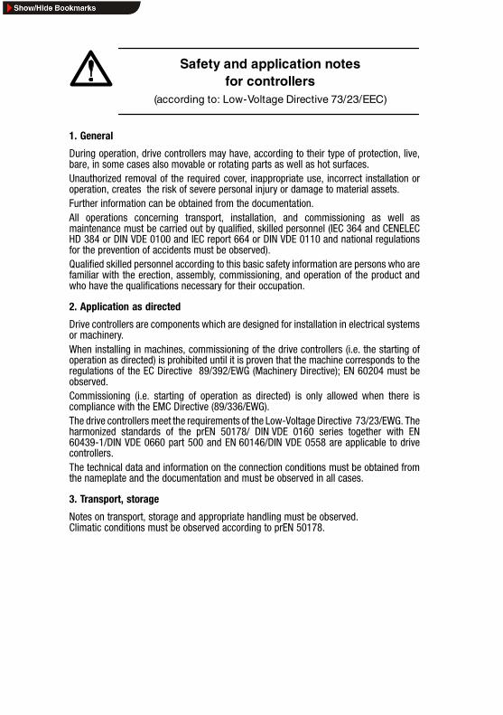
Safety and application notesfor controllers
(according to: Low-Voltage Directive 73/23/EEC)
1. General
During operation, drive controllers may have, according to their type of protection, live,bare, in some cases also movable or rotating parts as well as hot surfaces.Unauthorized removal of the required cover, inappropriate use, incorrect installation oroperation, creates the risk of severe personal injury or damage to material assets.Further information can be obtained from the documentation.All operations concerning transport, installation, and commissioning as well asmaintenance must be carried out by qualified, skilled personnel (IEC 364 and CENELECHD 384 or DIN VDE 0100 and IEC report 664 or DIN VDE 0110 and national regulationsfor the prevention of accidents must be observed).Qualified skilled personnel according to this basic safety information are persons who arefamiliar with the erection, assembly, commissioning, and operation of the product andwho have the qualifications necessary for their occupation.
2. Application as directed
Drive controllers are components which are designed for installation in electrical systemsor machinery.When installing in machines, commissioning of the drive controllers (i.e. the starting ofoperation as directed) is prohibited until it is proven that the machine corresponds to theregulations of the EC Directive 89/392/EWG (Machinery Directive); EN 60204 must beobserved.Commissioning (i.e. starting of operation as directed) is only allowed when there iscompliance with the EMC Directive (89/336/EWG).The drive controllers meet the requirements of the Low-Voltage Directive 73/23/EWG. Theharmonized standards of the prEN 50178/ DIN VDE 0160 series together with EN60439-1/DIN VDE 0660 part 500 and EN 60146/DIN VDE 0558 are applicable to drivecontrollers.The technical data and information on the connection conditions must be obtained fromthe nameplate and the documentation and must be observed in all cases.
3. Transport, storage
Notes on transport, storage and appropriate handling must be observed.Climatic conditions must be observed according to prEN 50178.
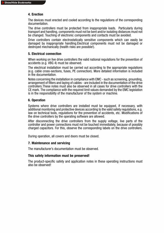
4. Erection
The devices must erected and cooled according to the regulations of the correspondingdocumentation.The drive controllers must be protected from inappropriate loads. Particularly duringtransport and handling, components must not be bent and/or isolating distances must notbe changed. Touching of electronic components and contacts must be avoided.Drive controllers contain electrostatically sensitive components which can easily bedamaged by inappropriate handling.Electrical components must not be damaged ordestroyed mechanically (health risks are possible!).
5. Electrical connection
When working on live drive controllers the valid national regulations for the prevention ofaccidents (e.g. VBG 4) must be observed.The electrical installation must be carried out according to the appropriate regulations(e.g. cable cross-sections, fuses, PE connection). More detailed information is includedin the documentation.Notes concerning the installation in compliance with EMC - such as screening, grounding,arrangement of filters and laying of cables - are included in the documentation of the drivecontrollers.These notes must also be observed in all cases for drive controllers with theCE mark. The compliance with the required limit values demanded by the EMC legislationis in the responsibility of the manufacturer of the system or machine.
6. Operation
Systems where drive controllers are installed must be equipped, if necessary, withadditional monitoring and protective devices according to the valid safety regulations, e.g.law on technical tools, regulations for the prevention of accidents, etc. Modifications ofthe drive controllers by the operating software are allowed.After disconnecting the drive controllers from the supply voltage, live parts of thecontroller and power connections must not be touched immediately, because of possiblycharged capacitors. For this, observe the corresponding labels on the drive controllers.
During operation, all covers and doors must be closed.
7. Maintenance and servicing
The manufacturer’s documentation must be observed.
This safety information must be preserved!
The product-specific safety and application notes in these operating instructions mustalso be observed!
Contents
8250BA0903 i
1 Preface and general information 1-1. . . . . . . . . . . . . . . . .1.1 About these Operating Instructions ... 1-1. . . . . . . . . . . . . . . . . . . . .
1.1.1 Terminology used 1-1. . . . . . . . . . . . . . . . . . . . . . . . . . . .1.1.2 What is new? 1-1. . . . . . . . . . . . . . . . . . . . . . . . . . . . . . .
1.2 Scope of delivery 1-2. . . . . . . . . . . . . . . . . . . . . . . . . . . . . . . . . . .1.3 825X brake units 1-2. . . . . . . . . . . . . . . . . . . . . . . . . . . . . . . . . . .
1.3.1 Labelling 1-2. . . . . . . . . . . . . . . . . . . . . . . . . . . . . . . . . .1.3.2 Application as directed 1-3. . . . . . . . . . . . . . . . . . . . . . . .1.3.3 Legal regulations 1-4. . . . . . . . . . . . . . . . . . . . . . . . . . . .
2 Safety information 2-1. . . . . . . . . . . . . . . . . . . . . . . . . . . .2.1 Personnel responsible for safety 2-1. . . . . . . . . . . . . . . . . . . . . . . . .2.2 General safety information 2-2. . . . . . . . . . . . . . . . . . . . . . . . . . . . .2.3 Layout of the safety information 2-3. . . . . . . . . . . . . . . . . . . . . . . . .2.4 Residual hazards 2-4. . . . . . . . . . . . . . . . . . . . . . . . . . . . . . . . . . .
3 Technical data 3-1. . . . . . . . . . . . . . . . . . . . . . . . . . . . . . .3.1 Features 3-1. . . . . . . . . . . . . . . . . . . . . . . . . . . . . . . . . . . . . . . . .3.2 General data /operating conditions 3-2. . . . . . . . . . . . . . . . . . . . . . .3.3 Rated data 3-3. . . . . . . . . . . . . . . . . . . . . . . . . . . . . . . . . . . . . . . .
3.3.1 Brake units 3-3. . . . . . . . . . . . . . . . . . . . . . . . . . . . . . . . .3.3.2 Assignment table for brake resistors 3-3. . . . . . . . . . . . . . .3.3.3 Overcurrent relay and cable cross-sections 3-4. . . . . . . . . .
3.4 Dimensions 3-4. . . . . . . . . . . . . . . . . . . . . . . . . . . . . . . . . . . . . . .
4 Installation 4-1. . . . . . . . . . . . . . . . . . . . . . . . . . . . . . . . . .4.1 Mechanical installation 4-1. . . . . . . . . . . . . . . . . . . . . . . . . . . . . . .
4.1.1 Important notes 4-1. . . . . . . . . . . . . . . . . . . . . . . . . . . . .4.1.2 Standard assembly with fixing rail 4-2. . . . . . . . . . . . . . . .4.1.3 DIN-rail assembly 4-3. . . . . . . . . . . . . . . . . . . . . . . . . . . .
4.2 Electrical installation 4-4. . . . . . . . . . . . . . . . . . . . . . . . . . . . . . . . .4.2.1 Operator’s safety 4-4. . . . . . . . . . . . . . . . . . . . . . . . . . . . .4.2.2 Protection of the brake unit 4-5. . . . . . . . . . . . . . . . . . . . .4.2.3 Specification of cables used 4-5. . . . . . . . . . . . . . . . . . . .
4.3 Connection 4-6. . . . . . . . . . . . . . . . . . . . . . . . . . . . . . . . . . . . . . . .4.3.1 Power connection 4-6. . . . . . . . . . . . . . . . . . . . . . . . . . . .4.3.2 8251 brake module on 820X controller 4-7. . . . . . . . . . . . .4.3.3 8252 brake module on 821X controller 4-8. . . . . . . . . . . . .4.3.4 8253 brake chopper on 821X controller 4-9. . . . . . . . . . . .4.3.5 Connect temperature monitoring 4-10. . . . . . . . . . . . . . . . .
Contents
ii 8250BA0903
5 Commissioning 5-1. . . . . . . . . . . . . . . . . . . . . . . . . . . . . .
6 Troubleshooting and fault elimination 6-1. . . . . . . . . . . .
7 Waste disposal 7-1. . . . . . . . . . . . . . . . . . . . . . . . . . . . . .
8 Supplement 8-1. . . . . . . . . . . . . . . . . . . . . . . . . . . . . . . . .8.1 Accessories 8-1. . . . . . . . . . . . . . . . . . . . . . . . . . . . . . . . . . . . . . .
8.1.1 Brake resistors 8-1. . . . . . . . . . . . . . . . . . . . . . . . . . . . .8.2 Glossary 8-3. . . . . . . . . . . . . . . . . . . . . . . . . . . . . . . . . . . . . . . . .8.3 Index 8-4. . . . . . . . . . . . . . . . . . . . . . . . . . . . . . . . . . . . . . . . . . . .
Preface and general information
8250BA0903 1-1
1 Preface and general information
1.1 About these Operating Instructions ...
• The present Operating Instructions are used for operationsconcerning safety measures on and with the 825X brakeunits. They contain safety information which must beobserved.
• All persons who work on and with 825X brake units musthave the Operating Instructions available and observe allrelevant notes and instructions.
• The Operating Instructions must always be in a completeand perfectly readable state.
1.1.1 Terminology used
Brake unit
The”8251 brakemodule”, the ”8252 brakemodule” or the”8253brake chopper with brake resistor” are called ”brake unit” in thefollowing text.
Controller
In the following text, the term ”controller” is used for ”82XXfrequency inverter”.
Drive system
For drive systems with 825X brake units and other Lenze drivecomponents, the term ”drive system” is used in the followingtext.
1.1.2 What is new?
Material No. Edition Important Contents
39365812/1996 1st edition
393658
01/1997 revised • Technical data• Chapter 4.3
474423 09/2003 replaces393658
• Change of company name• Chapter 8

Preface and general information
1-2 8250BA0903
1.2 Scope of delivery
• The scope of delivery includes:- 1 8251 brake module, 1 8252 brake module or 1 8253
brake chopper- 1 push-on terminal strip- 1 accessory kit with fixing material- 1 book of Operating Instructions
• After reception of the delivery, check immediately whetherthe scope of supply matches the accompanying papers.Lenze does not accept any liability for deficiencies claimedsubsequently. Claim- visible transport damage immediately to the forwarder.- visible deficiencies/incompleteness immediately to your
Lenze representative.
1.3 825X brake units
1.3.1 Labelling
• Lenze 825X brake units are clearly identified by theindications on the nameplate.
• CE mark- Conformity with the EC Low-Voltage Directive
• Manufacturer:- Lenze Drive Systems GmbH
Postfach 10 13 52D-31763 Hameln
Preface and general information
8250BA0903 1-3
1.3.2 Application as directed
8251 brake modules
• Additional units for Lenze controllers:- 820X frequency inverters (8201 to 8204)
8252 brake modules and 8253 brake choppers
• Additional units for Lenze controllers:- 821X frequency inverters (8211 to 8218)
825X brake units
• Operate the brake units only under the conditionsprescribed in these Operating Instructions.
• They are components- for installation in a machine- for assembly with other components to form a machine.
• They are electrical equipment for installation into controlcabinets or similar closed operating rooms.
• They meet the protection requirements of the EC Low-Voltage Directive.
• They are not machinery in the sense of the EC MachineryDirective.
• They are not household appliances but are intendedexclusively as components for further commercial use.
Drive systems with 825X brake units
• They correspond to the EC Electromagnetic CompatibilityDirective if they are installed according to the guidelines ofCE-typical drive systems.
• They can be operated- on public and non-public mains.- in industrial as well as residential and commercial
premises.
• The compliance with the EC Directives in machineapplication is in the responsibility of the user.
Any other use shall be deemed inappropriate!
Preface and general information
1-4 8250BA0903
1.3.3 Legal regulations
Liability
• The information, data, and notes in these OperatingInstructions met the state of the art at the time of printing.Claims referring to drive systems which have already beensupplied cannot be derived from the information,illustrations, and descriptions.
• The specifications, processes, and circuitry described inthese Operating Instructions are for guidance only andmust be adapted to your own specific application. Lenzedoes not take responsibility for the suitability of theprocess and circuit proposals.
• The indications given in these Operating Instructionsdescribe the features of the product without warrantingthem.
• Lenze does not accept any liability for damage andoperating interference caused by:- Disregarding these Operating instructions- Unauthorized changes of the brake units- Operating mistakes- Improper working on and with the brake units
Warranty
• Terms of warranty: see terms of sale and delivery of LenzeDrive Systems GmbH.
• Warranty claims must be made to Lenze immediately afterdetecting the deficiency or fault.
• The warranty is void in all cases where liability claimscannot be made.
Safety information
8250BA0903 2-1
2 Safety information
2.1 Personnel responsible for safety
Operator
• An operator is any natural or legal person who uses thedrive system or on behalf of whom the drive system isused.
• The operator or his safety officer are obliged- to check whether all relevant regulations, notes, and
laws are observed.- to ensure that only qualified personnel work with and on
the drive system.- to ensure that the personnel have the Operating
Instructions available for all corresponding operations- to prohibit non-qualified personnel from working with
and on the drive system.
Qualified personnel
Qualified personnel are persons who are - because of theireducation, experience, instructions, and knowledge aboutcorresponding standards and regulations, rules for theprevention of accidents, and operating conditions - authorizedby the person responsible for the safety of the plant to performthe required actions and who are able to recognize and avoidpotential hazards.(see IEC 364, definition of qualified personnel)

Safety information
2-2 8250BA0903
2.2 General safety information
• This safety information is not claimed to be complete. Incase of questions and problems please contact yourLenze representative.
• At the time of delivery the brake unit meets the state of theart and ensures basically safe operation.
• The indications given in these Operating Instructions referto the stated versions of the brake unit.
• The brake unit is hazardous for persons, the brake unititself and other property of the operator, if- non-qualified personnel work with and on the brake unit.- the brake unit is not used as directed.
• The specifications, processes, and circuitry described inthese Operating Instructions are for guidance only andmust be adapted to your own specific application.
• Brake units must be designed so that they comply withtheir function and do not cause any hazards for personsunder the conditions of correct installation and faultlessoperation as instructed. This is also effective for theinteraction with the complete plant.
• Take additional measures to limit consequences ofmalfunctions which may cause hazards for persons ormaterial assets:- Further independent equipment which can take over the
function of the brake unit- Electrical or non-electrical protection (latching or
mechanical blocking)- Measures covering the complete system
• Operate the drive system only in a perfect condition.
• Changes or retrofittings to the brake unit are prohibited inprinciple. In any case, Lenze must be contacted.
Safety information
8250BA0903 2-3
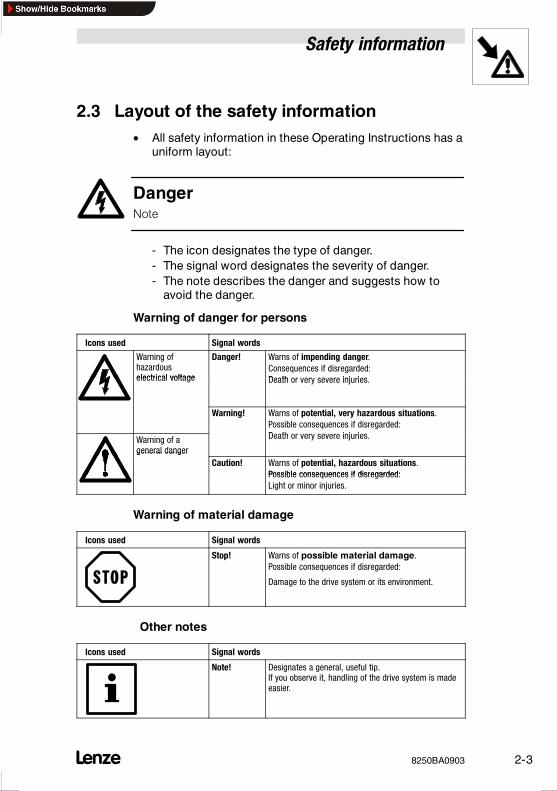
2.3 Layout of the safety information• All safety information in these Operating Instructions has a
uniform layout:
DangerNote
- The icon designates the type of danger.- The signal word designates the severity of danger.- The note describes the danger and suggests how to
avoid the danger.
Warning of danger for persons
Icons used Signal words
Warning ofhazardouselectrical voltage
Danger! Warns of impending danger.Consequences if disregarded:Death or very severe injurieselectrical voltage Death or very severe injuries.
Warning! Warns of potential, very hazardous situations.Possible consequences if disregarded:D th i j iWarning of a
general danger
q gDeath or very severe injuries.
general dangerCaution! Warns of potential, hazardous situations.
Possible consequences if disregarded:Possible consequences if disregarded:Light or minor injuries.
Warning of material damage
Icons used Signal words
Stop! Warns of possible material damage.Possible consequences if disregarded:
Damage to the drive system or its environment.
Other notes
Icons used Signal words
Note! Designates a general, useful tip.If you observe it, handling of the drive system is madeeasier.

Safety information
2-4 8250BA0903
2.4 Residual hazards
Protection of persons
After mains voltage disconnection the power terminals+UG, -UG remain live for 3 minutes.
Brake units may have surface temperatures of up to 130C forup to 30 minutes after mains disconnection.
Touching the brake unit may cause burns.
Technical Data
8250BA0903 3-1
3 Technical data
3.1 Features
• Three types:- 8251 brake module with internal brake resistor for
frequent braking operations with low load or infrequentbraking with medium load for operation with 820Xfrequency inverter
- 8252 brake module with internal brake resistor forfrequent braking operations with low load or infrequentbraking with medium load for operation with 8211- 8213frequency inverters
- 8253 brake chopper with external brake resistor forhigh-load continuous braking for operation with 821Xfrequency inverter
• Conversion of the mechanical braking energy into thermalenergy- Controller does not set pulse inhibit during braking, i.e.
the braking operation still remains controlled
• Very short braking times are possible
• Enclosure IP10 for installation in a control cabinet
• DIN-rail assembly possible (additional accessoriesrequired)
• Fixed thresholds for the mains voltages 230 V (8251) and400460 V (8252/8253)
• Current-state display via LED

Technical Data
3-2 8250BA0903
3.2 General data /operating conditions
Field Values
Vibration resistance Germanischer Lloyd, general conditions (in preparation)
Permissible moisture Humidity class F without condensation (medium relativehumidity 85 %)
Permissible temperature ranges during transport : -25 C +70 Cduring storage: -25 C +70 Cduring operation: 0 C +40 C
Permissible installation height h h 1000 m a.m.s.lwithout power derating1000 m a.m.s.l< h 4000 m a.m.s.lwith power derating
Degree of pollution VDE 0110 part 2 pollution degree 2
Insulation strength Overvoltage category III according to VDE 0110
Packing to DIN 4180
Type of protection IP10NEMA 1: Protection against contact
Approvals CE: Low-Voltage DirectiveEMC Directive in preparation
Technical Data
8250BA0903 3-3
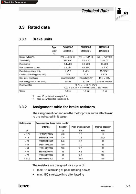
3.3 Rated data
3.3.1 Brake units
Type EMB8251-E EMB8252-E EMB8253-E
Orderno.
EMB8251-E EMB8252-E EMB8253-E
Supply voltage VN 270 400 V DC 270 750 V DC 270 750 V DC
Threshold VZ 375 V DC 725 V DC 725 V DC
Peak current 5.4 A DC 2.7 A DC 15 A DC
Max. continuous current 0.2 A DC 0.1 A DC 7.5 A DC
Peak braking power at VZ 2 kW1) 2 kW1) 11.2 kW2)
Continuous braking power at VZ 70 W 70 W 5.6 kW
Min. brake resistance (internal resistor) (internal resistor) 47 Ω 10%
Max. energy (min. 5 min break) 20 kWs 20 kWs (external resistor)
Power derating 40 C < T < 50 C: 2%/K1000 m a.m.s.l. < h < 4000 m a.m.s.l.: 5%/1000 m
Weight 1.3 kg 1.3 kg 1.1 kg
1) max. 10 s with switch-on cycle 3 %2) max. 60 s with switch-on cycle 50 %
3.3.2 Assignment table for brake resistors
The assignment depends on the motor power and is effectiveupto the indicated limit value.
Motor power Recommended Lenze brake resistoroto po e
Order no. Resistor Peak braking power Thermal capacity
kW Ω kW kWs
< 0.75 ERBM470R100W 470 1.0 15
< 1.5 ERBM370R150W 370 1.5 22,5
< 2.2 ERBM240R200W 240 2.0 30
< 3.0 ERBD180R300W 180 3.0 45
< 4.0 ERBD100R600W 100 5.5 90
< 5.5 ERBD082R600W 82 6.5 90
< 7.5 ERBD068R800W 68 8.0 120
< 11.0 ERBD047R01K2 47 11.5 180
The resistors are designed for a cycle of:
• max. 15 s braking at peak braking power
• min. 150 s release time after braking

Technical Data
3-4 8250BA0903
3.3.3 Overcurrent relay and cable cross-sections
With a cable cross section of the feeding inverter of > 2.5 mm2,
the cable can be protected via overcurrent relay.
The cable cross-sections used must meet the valid regulations.We recommend:
Type Input +UG, -UG
Overcurrent relay Cable cross-section
[A] [mm2]
8251 not required 1.5
8252 not required 1.5
8253 max 12 * 2.5
* depending on the brake resistor
3.4 Dimensions
The dimensions of the brake units depend on the mechanicalinstallation (see chapter 4.1)
Installation
8250BA0903 4-1
4 Installation
4.1 Mechanical installation
4.1.1 Important notes
• Use the brake units only as built-in devices!
• Observe free space!- Allow a free space of 100 mm at the top and at the
bottom.
• Ensure unimpeded ventilation of cooling air and outlet ofexhaust air.
• If the cooling air contains pollutants (dust, fluff, grease,aggressive gases ), which may impair the function of thebrake units:- Take suitable preventive measures , e.g. separate air
duct, installation of filters, regular cleaning, etc.
• Do not exceed the permissible range of the operatingambient temperature (see chapter 3.2).
• If the brake units are permanently subjected to vibration orshaking:- Check whether shock absorbers are necessary.
Danger!
Operation with 8253 brake chopper and external brake resistor:
• In the event of failures, brake resistors can become veryhot, they can even burn. E.g. when the following occurs:- mains overvoltage,- application-specific overload,- internal fault.
• Brake resistors must therefore be installed such that thevery high temperatures possible cannot cause anydamage.
Installation
4-2 8250BA0903
Possible mounting positions
• In vertical position at the backside of the control cabinet.- terminal strip at the bottom- assembled on attached fixing rail (see chapter 4.1.2) or
DIN rail (see chapter 4.1.3)
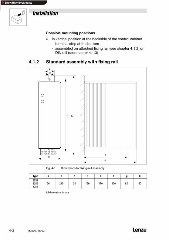
4.1.2 Standard assembly with fixing rail
-UG +UG RB1 RB2 PE (T1) (T2)
a e
b
f
d
gk
Fig. 4-1 Dimensions for fixing-rail assembly
Type a b c d e f g k
825182528253
56 210 28 190 170 130 6.5 30
All dimensions in mm
Installation
8250BA0903 4-3
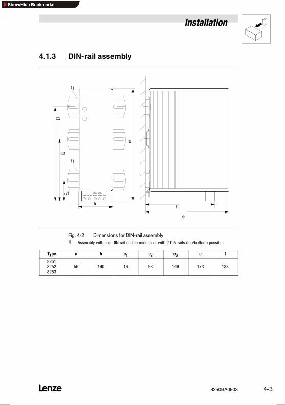
4.1.3 DIN-rail assembly
1)
1)
-UG +UG RB1 RB2 PE (T1) (T2)
a
e
b
c1
c2
c3
f
Fig. 4-2 Dimensions for DIN-rail assembly1) Assembly with one DIN rail (in the middle) or with 2 DIN rails (top/bottom) possible.
Type a b c1 c2 c3 e f
825182528253
56 190 16 98 149 173 133
Installation
4-4 8250BA0903
4.2 Electrical installation
4.2.1 Operator’s safety
Danger!After switching off the mains voltage, all power terminals (+UG,-UG and RB1, RB2) of the brake unit remain live for up to3 minutes.Therefore please wait for 3 minutes after having switched off themains voltage before you start to work.
- For single drives, the brake unit carries a hazardousvoltage up to three minutes after mains disconnection.
- In a drive network, all controllers must be inhibited anddisconnected from the mains.
Danger!During braking operation (e.g. test stand, high inertia loads etc.)the voltage is still present after mains switching (OFF).It is therefore necessary to set all controllers to controller inhibit.
Installation
8250BA0903 4-5
4.2.2 Protection of the brake unit
Stop!
The brake units contain electrostatically sensitive components.
• Prior to assembly and service operations, the personnelmust be free of electrostatic charge:- They can discharge themselves by touching the PE
fixing screw or another grounded metal part in thecontrol cabinet.
• In the event of condensation connect the brake unit tomains voltage only after the visible humidity hasevaporated.
4.2.3 Specification of cables used
• The cables used must comply with the approvals requiredat the site (eg. UL).
• The prescribed minimum cross-sections of PE conductorsmust be maintained in all cases. The cross-section of thePE conductor must be at least as large as thecross-section of the power connections (VDE 0160).
• The screening quality of a cable is determined by- a good screen connection- a low screen resistance
Use only screens with tin-plated or nickel-plated copperbraid!Screens of steel braid are not suitable.
- the degree of coverage of the screen braid:at least 70% to 80% with a coverage angle of 90
Note!The screens are only required to comply with existing standards(e.g. VDE 0160, EN 50178).
Installation
4-6 8250BA0903
4.3 Connection
4.3.1 Power connection
• All indications about cable cross-sections arerecommendations and refer to the application:- in control cabinets and machines- in cable ducts- at a max. ambient temperature +40 C
• The compliance with other standards (e.g.: VDE 0113, VDE0289, etc.) remains the responsibility of the user.
• The cables between brake unit and controller must not belonger than max. 2 m.
• If the brake unit is directly connected with the controllerand the cable length does not exceed 0.5 m, the cablescan be used as unscreened single cores.
• For a radio interference suppression (limit-value class A orB) to DIN 55011 observe the following:- The cables must be screened.- For cable lengths up to 1 m it is sufficient to connect the
screen at the middle.- For cable lengths > 1 m, the screen must always be
connected on both sides.
Connection
• The cables between controller and brake unit must beDC-bus connected to the terminals +UG, -UG.
• Observe stud torques:
Terminals 0.5 ... 0.6 Nme a s
4.4 ... 5.3 lbfin
Installation
8250BA0903 4-7
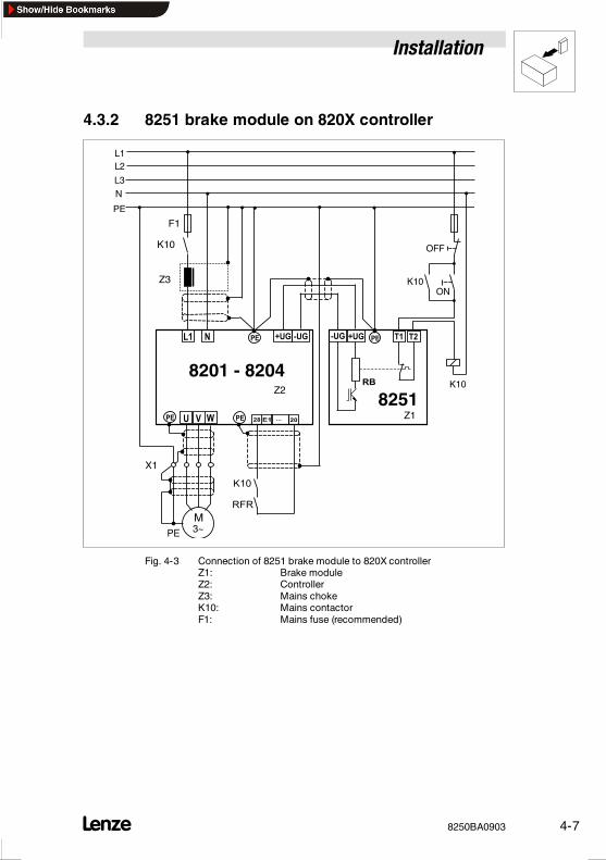
4.3.2 8251 brake module on 820X controller
K10
L3
N
PE
L1L2
M3~PE
K10
F1
8201 - 8204
8251 Z1
X1
Z2
K10
OFF
ONZ3
Fig. 4-3 Connection of 8251 brake module to 820X controllerZ1: Brake moduleZ2: ControllerZ3: Mains chokeK10: Mains contactorF1: Mains fuse (recommended)
Installation
4-8 8250BA0903
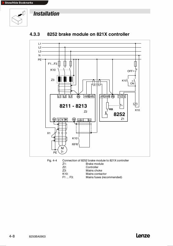
4.3.3 8252 brake module on 821X controller
L3
N
PE
L1L2
M3~PE
K10
F1...F3
8211 - 8213
8252 Z1
X1
Z2
Z3
K10
OFF
ON
K10
Fig. 4-4 Connection of 8252 brake module to 821X controllerZ1: Brake moduleZ2: ControllerZ3: Mains chokeK10: Mains contactorF1 ... F3: Mains fuses (recommended)
Installation
8250BA0903 4-9
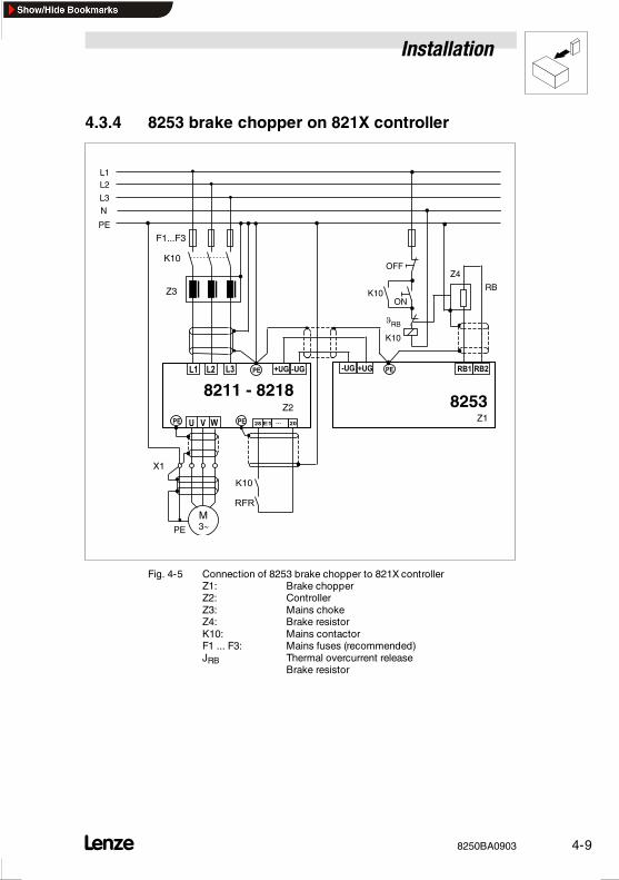
4.3.4 8253 brake chopper on 821X controller
L3
N
PE
L1L2
M3~PE
8211 - 82188253
Z1
X1
Z2
Z3
K10
OFF
ON
RB
Z4
K10
RB
K10
F1...F3
Fig. 4-5 Connection of 8253 brake chopper to 821X controllerZ1: Brake chopperZ2: ControllerZ3: Mains chokeZ4: Brake resistorK10: Mains contactorF1 ... F3: Mains fuses (recommended)JRB Thermal overcurrent release
Brake resistor
Installation
4-10 8250BA0903
4.3.5 Connect temperature monitoring
Danger!Thetemperaturemonitoring is required to ensuresafeswitch-offin the event of a failure.
Use the thermostats of the brake resistors to
• separate the controller from the mains if the temperaturemonitoring is activated
and
• set controller inhibit in all connected controllers.
For connection of the thermostat: see the correspondingsignal-flow diagrams (chapter 4.3.2 4.3.4).

Commissioning
8250BA0903 5-1
5 Commissioning
Stop!If theconnections +UG and -UGarereserved, thebrakeunits andall connected components can be destroyed.It is therefore absolutely necessary to check the correctconnection of the terminals before switching on the unit.
The two LEDs at the brake unit indicate the operating state:
• green LED:illuminated, when the brake unit is supplied with voltageand is ready for operation
• yellow LED:illuminated, when brake unit is in braking operation
Note!The deceleration time of the drive will be prolonged if thefeedback power is higher than the peak brake power of theassigned brake resistor. In this case, the controller sets pulseinhibit and indicates „overvoltage“.Prolong the Tif-time via the deceleration ramp at theramp-function generator or theQSPramp at thecontroller orusea lower-value brake resistor, if permitted.
Commissioning
5-2 8250BA0903

Troubleshooting and fault elimination
8250BA0903 6-1
6 Troubleshooting and fault eliminationFault Cause Remedy
Green LED is not illuminated No voltage at terminals +UG, -UG • Switch on the mains• Connect the brake unit to theterminals +UG, -UG of thecontroller
Controller sets pulse inhibit duringbraking and indicates overvoltage
• Yellow LED is not illuminated The brake unit is not connected tothe terminals +UG, -UG of thecontroller
Connect the brake unit to theterminals +UG, -UG of the controller
• Yellow LED is illuminated Brake resistor is not connected Connect brake resistor
Brake resistance too high Use lower-value brake resistor
Troubleshooting and fault elimination
6-2 8250BA0903
Waste disposal
8250BA0903 7-1
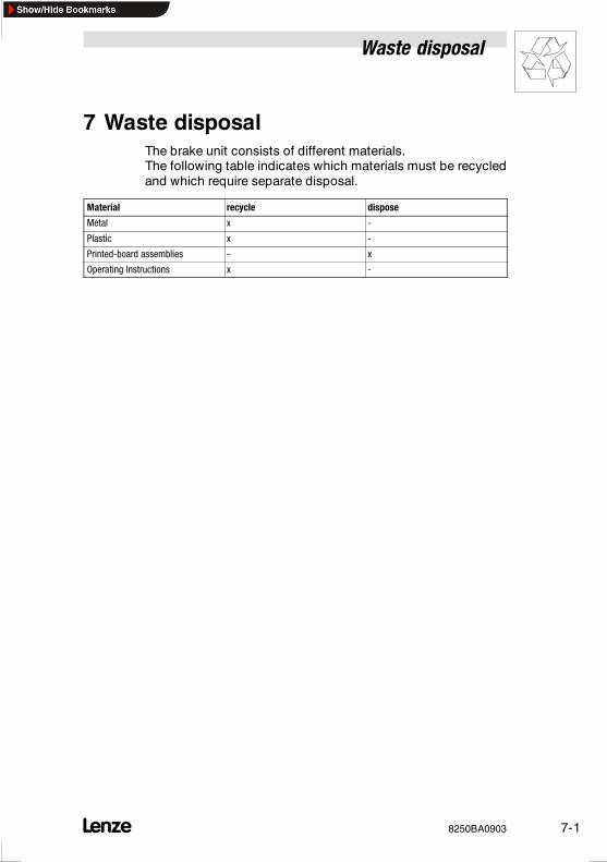
7 Waste disposalThe brake unit consists of different materials.The following table indicates which materials must be recycledand which require separate disposal.
Material recycle dispose
Metal x -
Plastic x -
Printed-board assemblies - x
Operating Instructions x -
Waste disposal
7-2 8250BA0903
Appendix
8250BA0903 8-1
8 Supplement
8.1 Accessories
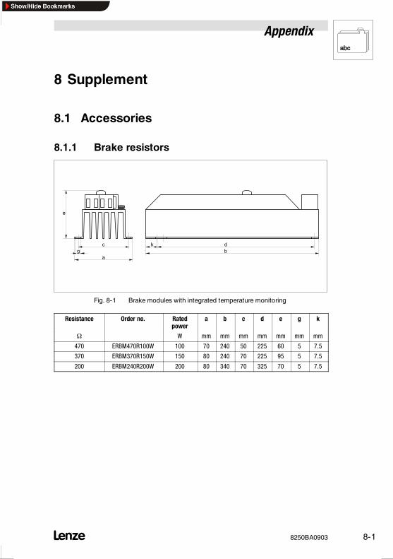
8.1.1 Brake resistors
Fig. 8-1 Brake modules with integrated temperature monitoring
Resistance Order no. Ratedpower
a b c d e g k
Ω W mm mm mm mm mm mm mm
470 ERBM470R100W 100 70 240 50 225 60 5 7.5
370 ERBM370R150W 150 80 240 70 225 95 5 7.5
200 ERBM240R200W 200 80 340 70 325 70 5 7.5
Appendix
8-2 8250BA0903
c
a
f
de
b
g
h
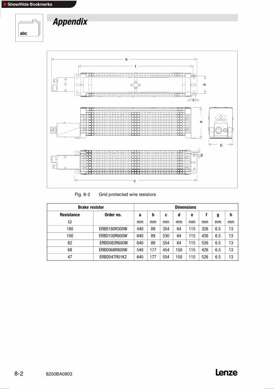
Fig. 8-2 Grid protected wire resistors
Brake resistor Dimensions
Resistance Order no. a b c d e f g h
Ω mm mm mm mm mm mm mm mm
180 ERBD180R300W 440 89 354 64 115 326 6.5 13
100 ERBD100R600W 640 89 530 64 115 426 6.5 13
82 ERBD082R600W 640 89 554 64 115 526 6.5 13
68 ERBD068R800W 540 177 454 150 115 426 6.5 13
47 ERBD047R01K2 640 177 554 150 115 526 6.5 13
Appendix
8250BA0903 8-3
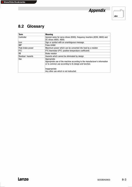
8.2 Glossary
Term MeaningController General name for servo drives (93XX), frequency inverters (82XX, 86XX) and
DC drives (48XX, 49XX)Icon Sign or symbol with an unambiguous message.IMP Pulse inhibitPeak brake power Maximum power which can be converted into heat by a resistorPTC PTC thermistor (PTC: positive temperature coefficient)RB Brake resistorResidual hazards Hazards which cannot be eliminated by designUse Appropriate:
Appropriate use of the machine according to the manufacturer’s informationor to common use according to its design and function.
Inappropriate:Any other use which is not instructed.
Appendix
8-4 8250BA0903
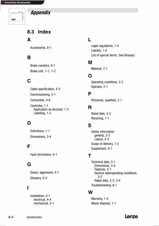
8.3 Index
A
Accessories, 8-1
B
Brake resistors, 8-1
Brake unit, 1-1, 1-2
C
Cable specification, 4-5
Commissioning, 5-1
Connection, 4-6
Controller, 1-1Application as directed, 1-3Labelling, 1-2
D
Definitions, 1-1
Dimensions, 3-4
F
Fault elimination, 6-1
G
Gases, aggressive, 4-1
Glossary, 8-3
I
Installation, 4-1electrical, 4-4mechanical, 4-1
LLegal regulations, 1-4Liability, 1-4List of special terms. See Glossary
MMaterial, 7-1
OOperating conditions, 3-2Operator, 2-1
PPersonnel, qualified, 2-1
RRated data, 3-3Recycling, 7-1
SSafety informationgeneral, 2-2Layout, 2-3
Scope of delivery, 1-2Supplement, 8-1
TTechnical data, 3-1Dimensions, 3-4Features, 3-1General data/operating conditions,3-2
Rated data, 3-3, 3-4Troubleshooting, 6-1
WWarranty, 1-4Waste disposal, 7-1