operating instructions 07/2007 edition - siemens ag · operating instructions 07/2007 edition. ......
TRANSCRIPT

sinamics
s
SINAMICS G130/G150Line harmonics filter
Operating Instructions 07/2007 Edition


Safety information 1
General 2
Mechanical installation 3
Electrical installation 4
Maintenance and servicing 5
Technical specifications 6
SINAMICS
SINAMICS G130/G150Line harmonics filters
Operating Instructions
07/07 A5E01347987A
Control version V2.5
Safety Guidelines This manual contains notices you have to observe in order to ensure your personal safety, as well as to prevent damage to property. The notices referring to your personal safety are highlighted in the manual by a safety alert symbol, notices referring only to property damage have no safety alert symbol. These notices shown below are graded according to the degree of danger.
DANGER indicates that death or severe personal injury will result if proper precautions are not taken.
WARNING indicates that death or severe personal injury may result if proper precautions are not taken.
CAUTION with a safety alert symbol, indicates that minor personal injury can result if proper precautions are not taken.
CAUTION without a safety alert symbol, indicates that property damage can result if proper precautions are not taken.
NOTICE indicates that an unintended result or situation can occur if the corresponding information is not taken into account.
If more than one degree of danger is present, the warning notice representing the highest degree of danger will be used. A notice warning of injury to persons with a safety alert symbol may also include a warning relating to property damage.
Qualified Personnel The device/system may only be set up and used in conjunction with this documentation. Commissioning and operation of a device/system may only be performed by qualified personnel. Within the context of the safety notes in this documentation qualified persons are defined as persons who are authorized to commission, ground and label devices, systems and circuits in accordance with established safety practices and standards.
Prescribed Usage Note the following:
WARNING This device may only be used for the applications described in the catalog or the technical description and only in connection with devices or components from other manufacturers which have been approved or recommended by Siemens. Correct, reliable operation of the product requires proper transport, storage, positioning and assembly as well as careful operation and maintenance.
Trademarks All names identified by ® are registered trademarks of the Siemens AG. The remaining trademarks in this publication may be trademarks whose use by third parties for their own purposes could violate the rights of the owner.
Disclaimer of Liability We have reviewed the contents of this publication to ensure consistency with the hardware and software described. Since variance cannot be precluded entirely, we cannot guarantee full consistency. However, the information in this publication is reviewed regularly and any necessary corrections are included in subsequent editions.
Siemens AG Automation and Drives Postfach 48 48 90327 NÜRNBERG GERMANY
A5E01347987A Ⓟ 09/2007
Copyright © Siemens AG 2007. Technical data subject to change

Line harmonics filters Operating Instructions, 07/07, A5E01347987A 5
Table of contents 1 Safety information...................................................................................................................................... 7
1.1 Warnings ........................................................................................................................................7 1.2 Safety and operating instructions...................................................................................................8
2 General...................................................................................................................................................... 9 3 Mechanical installation............................................................................................................................. 15
3.1 General ........................................................................................................................................15 3.2 Dimension drawings.....................................................................................................................16
4 Electrical installation ................................................................................................................................ 19 5 Maintenance and servicing ...................................................................................................................... 25 6 Technical specifications........................................................................................................................... 27

Table of contents
Line harmonics filters 6 Operating Instructions, 07/07, A5E01347987A

Line harmonics filters Operating Instructions, 07/07, A5E01347987A 7
Safety information 11.1 Warnings
WARNING
Hazardous voltages are present when electrical equipment is in operation. Severe personal injury or substantial material damage may result if these warnings are not observed. Only qualified personnel are permitted to work on or around the equipment. This personnel must be thoroughly familiar with all the warnings and maintenance procedures described in these operating instructions. Correct and safe operation of this device assumes correct transportation, storage, setup, and installation, as well as careful operation and maintenance.. National safety guidelines must be observed.

Safety information 1.2 Safety and operating instructions
Line harmonics filters 8 Operating Instructions, 07/07, A5E01347987A
1.2 Safety and operating instructions
DANGER
This equipment is used in industrial high-voltage installations. During operation, this equipment contains rotating and live, bare parts. For this reason, they could cause severe injury or significant material damage if the required covers are removed, if they are used or operated incorrectly, or have not been properly maintained. When the machines are used in non-industrial areas, the installation location must be protected against unauthorized access (protective fencing, appropriate signs).
Prerequisites Those responsible for protecting the plant must ensure the following: ● The basic planning work for the plant and the transport, assembly, installation,
commissioning, maintenance, and repair work is carried out by qualified personnel and/or checked by experts responsible.
● The operating manual and machine documentation are always available. ● The technical specifications regarding the applicable installation, connection,
environmental, and operating conditions are always observed. ● The plant-specific assembly and safety guidelines are observed and personal protection
equipment is used. ● Unqualified personnel are forbidden from using these machines and working near them. This operating manual is intended for qualified personnel and only contain information and notes relating to the intended purpose of the machines. The operating manual and machine documentation are written in different languages as specified in the delivery contracts.
Note We recommend engaging the support and services of your local Siemens service center for all planning, installation, commissioning and maintenance work.
Line harmonics filters Operating Instructions, 07/07, A5E01347987A 9
General 2Description
Line harmonics filters are drive components designed for installation in electrical systems or machines. They must not be used in other electrical consumers since this could destroy the devices.
WARNING Line harmonics filters must only be connected to symmetrical networks otherwise they can be destroyed.
General
Line harmonics filters 10 Operating Instructions, 07/07, A5E01347987A
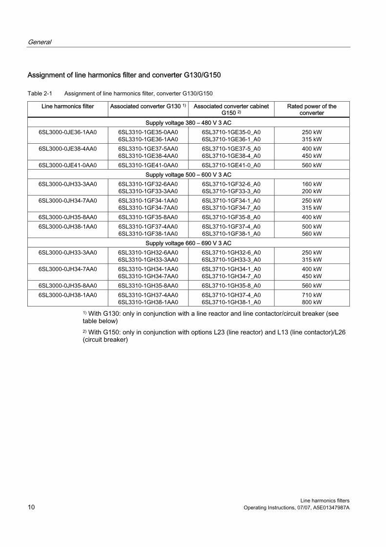
Assignment of line harmonics filter and converter G130/G150
Table 2-1 Assignment of line harmonics filter, converter G130/G150
Line harmonics filter Associated converter G130 1) Associated converter cabinet G150 2)
Rated power of the converter
Supply voltage 380 – 480 V 3 AC 6SL3000-0JE36-1AA0 6SL3310-1GE35-0AA0
6SL3310-1GE36-1AA0 6SL3710-1GE35-0_A0 6SL3710-1GE36-1_A0
250 kW 315 kW
6SL3000-0JE38-4AA0 6SL3310-1GE37-5AA0 6SL3310-1GE38-4AA0
6SL3710-1GE37-5_A0 6SL3710-1GE38-4_A0
400 kW 450 kW
6SL3000-0JE41-0AA0 6SL3310-1GE41-0AA0 6SL3710-1GE41-0_A0 560 kW Supply voltage 500 – 600 V 3 AC
6SL3000-0JH33-3AA0 6SL3310-1GF32-6AA0 6SL3310-1GF33-3AA0
6SL3710-1GF32-6_A0 6SL3710-1GF33-3_A0
160 kW 200 kW
6SL3000-0JH34-7AA0 6SL3310-1GF34-1AA0 6SL3310-1GF34-7AA0
6SL3710-1GF34-1_A0 6SL3710-1GF34-7_A0
250 kW 315 kW
6SL3000-0JH35-8AA0 6SL3310-1GF35-8AA0 6SL3710-1GF35-8_A0 400 kW 6SL3000-0JH38-1AA0 6SL3310-1GF37-4AA0
6SL3310-1GF38-1AA0 6SL3710-1GF37-4_A0 6SL3710-1GF38-1_A0
500 kW 560 kW
Supply voltage 660 – 690 V 3 AC 6SL3000-0JH33-3AA0 6SL3310-1GH32-6AA0
6SL3310-1GH33-3AA0 6SL3710-1GH32-6_A0 6SL3710-1GH33-3_A0
250 kW 315 kW
6SL3000-0JH34-7AA0 6SL3310-1GH34-1AA0 6SL3310-1GH34-7AA0
6SL3710-1GH34-1_A0 6SL3710-1GH34-7_A0
400 kW 450 kW
6SL3000-0JH35-8AA0 6SL3310-1GH35-8AA0 6SL3710-1GH35-8_A0 560 kW 6SL3000-0JH38-1AA0 6SL3310-1GH37-4AA0
6SL3310-1GH38-1AA0 6SL3710-1GH37-4_A0 6SL3710-1GH38-1_A0
710 kW 800 kW
1) With G130: only in conjunction with a line reactor and line contactor/circuit breaker (see table below) 2) With G150: only in conjunction with options L23 (line reactor) and L13 (line contactor)/L26 (circuit breaker)

General
Line harmonics filters Operating Instructions, 07/07, A5E01347987A 11
Table 2-2 Assignment of converter G130, line contactor, and line reactor
SINAMICS G130 Rated power Line contactor/circuit breaker Line reactor Supply voltage 380 – 480 V 3 AC
6SL3310-1GE35-0AA0 250 kW 3RT1476-6AP36 6SL3000-0CE35-1AA0 6SL3310-1GE36-1AA0 315 kW 3RT1476-6AP36 6SL3000-0CE36-3AA0 6SL3310-1GE37-5AA0 400 kW 3 x 3RT1466-6AP36 6SL3000-0CE37-7AA0 6SL3310-1GE38-4AA0 450 kW 3WL1110-2BB34-4AN2-Z, Z=22 6SL3000-0CE38-7AA0 6SL3310-1GE41-0AA0 560 kW 3WL1210-2BB34-4AN2-Z, Z=22 6SL3000-0CE41-0AA0
Supply voltage 500 – 600 V 3 AC 6SL3310-1GF32-6AA0 160 kW 3RT1466-6AP36 6SL3000-0CH32-7AA0 6SL3310-1GF33-3AA0 200 kW 3RT1466-6AP36 6SL3000-0CH33-4AA0 6SL3310-1GF34-1AA0 250 kW 3RT1476-6AP36 6SL3000-0CH34-8AA0 6SL3310-1GF34-7AA0 315 kW 3RT1476-6AP36 6SL3000-0CH34-8AA0 6SL3310-1GF35-8AA0 400 kW 3RT1476-6AP36 6SL3000-0CH36-0AA0 6SL3310-1GF37-4AA0 450 kW 3 x 3RT1466-6AP36 6SL3000-0CH38-4AA0 6SL3310-1GF38-1AA0 560 kW 3WL1210-4BB34-4AN2-Z, Z=22 6SL3000-0CH38-4AA0
Supply voltage 660 – 690 V 3 AC 6SL3310-1GH32-6AA0 250 kW 3RT1466-6AP36 6SL3000-0CH32-7AA0 6SL3310-1GH33-3AA0 315 kW 3RT1466-6AP36 6SL3000-0CH33-4AA0 6SL3310-1GH34-1AA0 400 kW 3RT1476-6AP36 6SL3000-0CH34-8AA0 6SL3310-1GH34-7AA0 450 kW 3RT1476-6AP36 6SL3000-0CH34-8AA0 6SL3310-1GH35-8AA0 560 kW 3RT1476-6AP36 6SL3000-0CH36-0AA0 6SL3310-1GH37-4AA0 710 kW 3 x 3RT1466-6AP36 6SL3000-0CH38-4AA0 6SL3310-1GH38-1AA0 800 kW 3WL1210-4BB34-4AN2-Z, Z=22 6SL3000-0CH38-4AA0
Line system configurations If you want to operate the filter modules with line systems not specified in the table below, please contact our technical department.
VDE-compliant line system configuration Operating the line harmonics filter
With directly grounded star point Permitted With indirectly grounded star point Permitted
With isolated star point Permitted
General
Line harmonics filters 12 Operating Instructions, 07/07, A5E01347987A
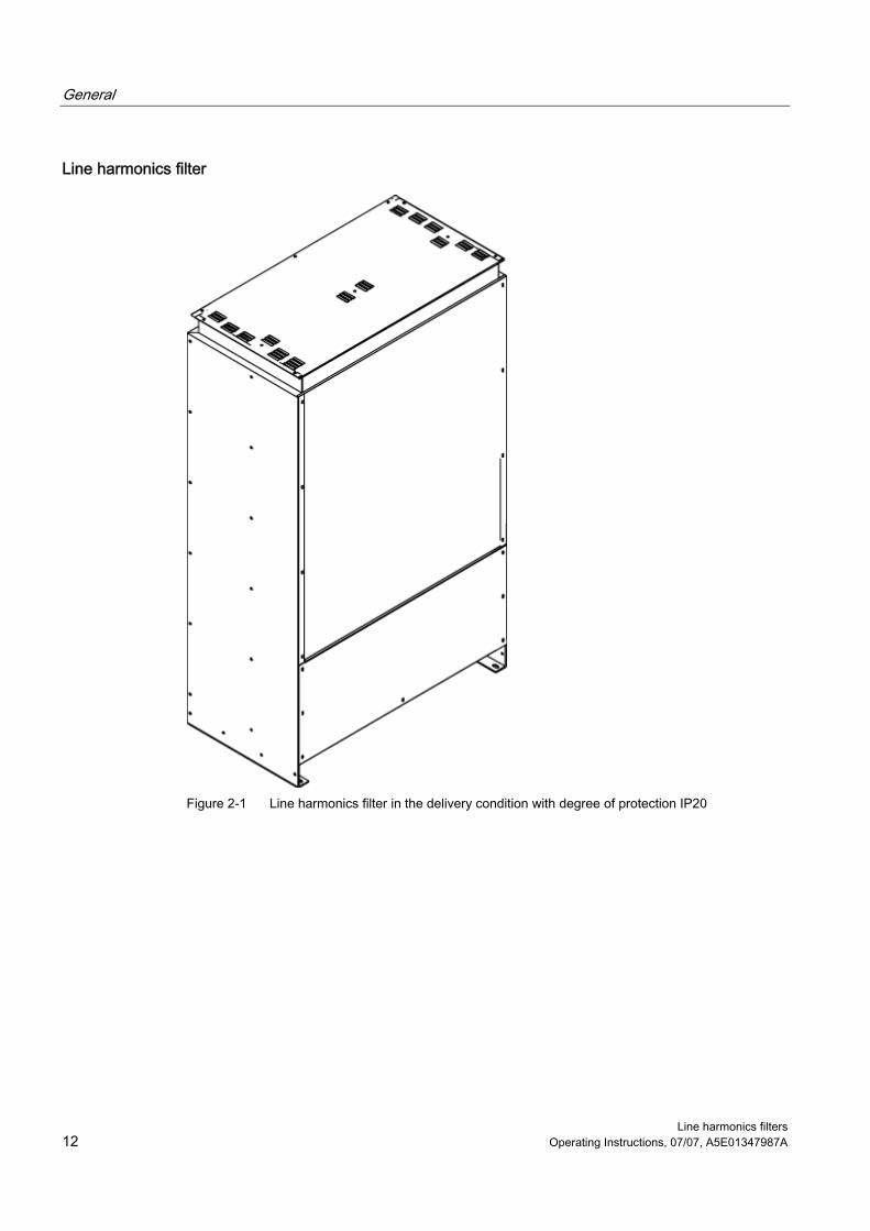
Line harmonics filter
Figure 2-1 Line harmonics filter in the delivery condition with degree of protection IP20

General
Line harmonics filters Operating Instructions, 07/07, A5E01347987A 13
Figure 2-2 Line harmonics filter with mounted canopy and degree of protection IP21

General
Line harmonics filters 14 Operating Instructions, 07/07, A5E01347987A

Line harmonics filters Operating Instructions, 07/07, A5E01347987A 15
Mechanical installation 33.1 General
WARNING To ensure that the devices operate safely and reliably, they must be properly installed and commissioned by qualified personnel, taking into account the warnings provided in these operating instructions. In particular, the general and national installation and safety guidelines for high-voltage installations (e.g. VDE – the Union of German Technical Engineers) as well as the guidelines relating to the proper use of tools and personal protective equipment must be observed. Death, serious injury, or substantial material damage can result if these factors are not taken into account.
Note
A ventilation clearance of at least 60 mm at the rear of the line harmonics filter must be observed. Natural convection must not be obstructed.
Installing the canopy to increase the degree of protection to IP21 The canopy supplied can be installed on the line harmonics filter to increase the degree of protection to IP21. To install it, the spacers supplied with the line harmonics filter must be screwed into the holes otherwise used for the cover. Use the screws you removed earlier (incl. washers and retaining rings) to secure the canopy.

Mechanical installation 3.2 Dimension drawings
Line harmonics filters 16 Operating Instructions, 07/07, A5E01347987A
3.2 Dimension drawings
Figure 3-1 Dimension drawing of line harmonics filter: 6SL3000-0JE36-1AA0, 6SL3000-0JH33-
3AA0

Mechanical installation 3.2 Dimension drawings
Line harmonics filters Operating Instructions, 07/07, A5E01347987A 17
Figure 3-2 Dimension drawing of line harmonics filter: 6SL3000-0JE38-4AA0, 6SL3000-0JH34-7AA0

Mechanical installation 3.2 Dimension drawings
Line harmonics filters 18 Operating Instructions, 07/07, A5E01347987A
Figure 3-3 Dimension drawing of line harmonics filter: 6SL3000-0JE41-0AA0, 6SL3000-0JH35-8AA0, 6SL3000-0JH38-
1AA0

Line harmonics filters Operating Instructions, 07/07, A5E01347987A 19
Electrical installation 4Important safety precautions
WARNING The line harmonics filters are operated with high voltages. All connection procedures must be carried out when the cabinet is de-energized. All work on the device must be carried out by trained personnel only. Death, serious injury, or substantial material damage can result if these warnings are not taken into account. Work on an open device must be carried out with extreme caution. The power and control terminals may be live even when the motor is not running. Due to the capacitors, dangerously high voltage levels are still present in the cabinet up to five minutes after it has been disconnected. For this reason, the cabinet should not be opened until a reasonable period of time has elapsed. The operator is responsible for ensuring that the motor, converter, and other devices are installed and connected in accordance with the recognized technical rules in the country of installation and applicable regional guidelines. Special attention should be paid to cable dimensioning, fuses, grounding, shutdown, disconnection, and overcurrent protection. If an item of protective gear trips in a branch circuit, a leakage current may have been disconnected. To reduce the risk of fire or an electric shock, the current-carrying parts and other components in the cabinet unit should be inspected and damaged parts replaced. When an item of protective gear trips, the cause of the trip must be identified and rectified. When the line harmonics filter is connected to a network with a line frequency of 60 Hz, the cable jumpers must be removed in accordance with the instructions in the device (see interface overviews below).
Tightening torques for connecting current-carrying parts When securing connections for current-carrying parts (e.g. copper bars), you must observe the following tightening torques.
Table 4-1 Tightening torques for connecting current-carrying parts
Screw Torque M6 6 Nm M8 13 Nm
M10 25 Nm M12 50 Nm
Electrical installation
Line harmonics filters 20 Operating Instructions, 07/07, A5E01347987A
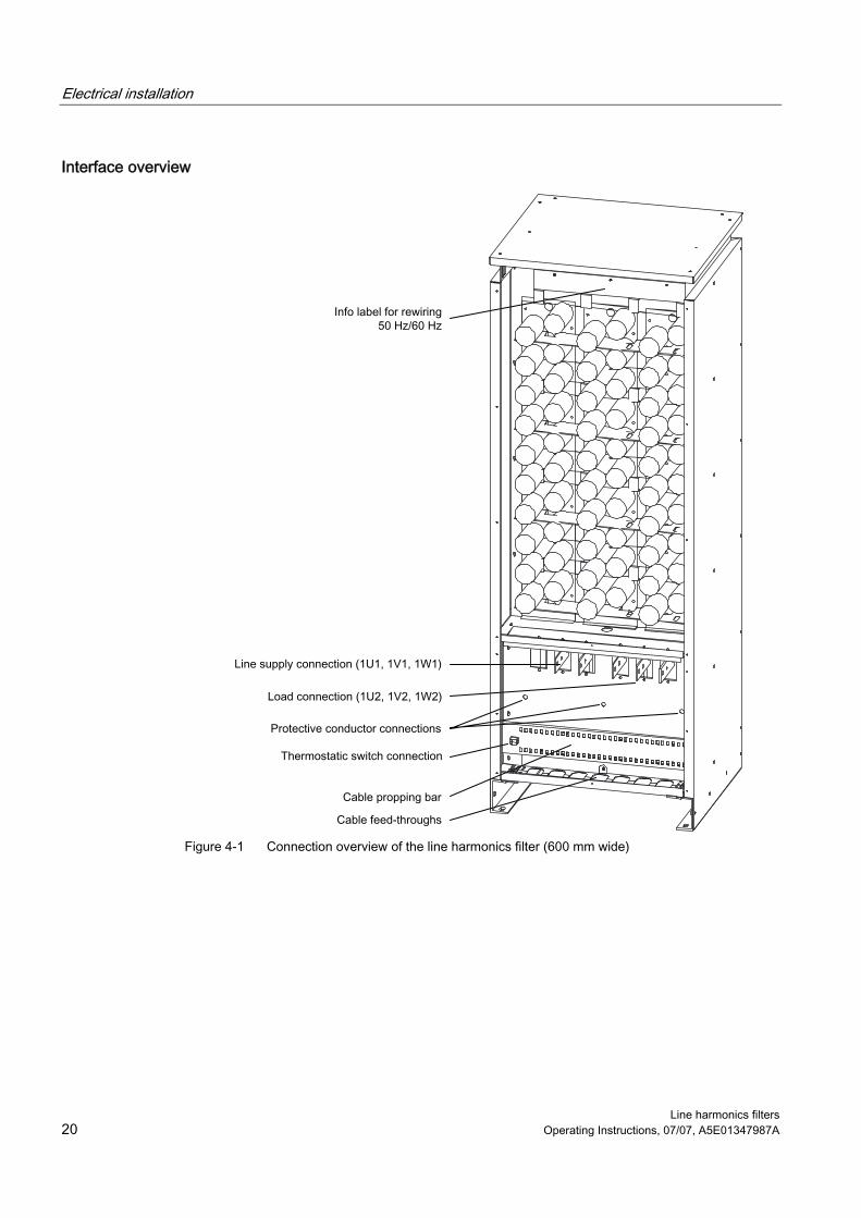
Interface overview
Figure 4-1 Connection overview of the line harmonics filter (600 mm wide)
Electrical installation
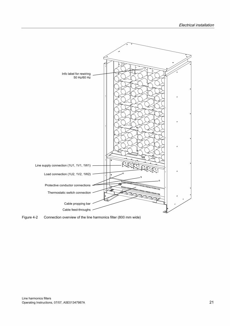
Line harmonics filters Operating Instructions, 07/07, A5E01347987A 21
Figure 4-2 Connection overview of the line harmonics filter (800 mm wide)
Electrical installation
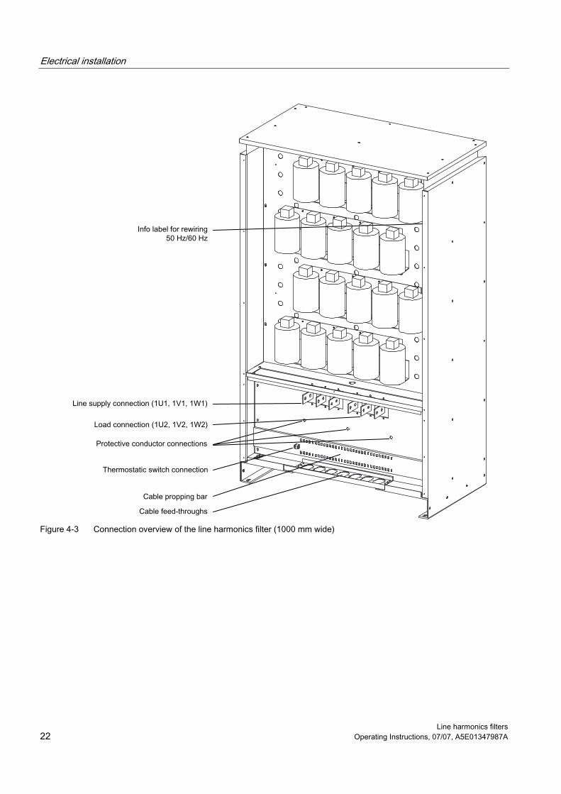
Line harmonics filters 22 Operating Instructions, 07/07, A5E01347987A
Figure 4-3 Connection overview of the line harmonics filter (1000 mm wide)

Electrical installation
Line harmonics filters Operating Instructions, 07/07, A5E01347987A 23
Connecting the line harmonics filter for SINAMICS G150
L 1
L 2
L 3
N PE
M 3 ~
Figure 4-4 Connecting the line harmonics filter for SINAMICS G150

Electrical installation
Line harmonics filters 24 Operating Instructions, 07/07, A5E01347987A
Connecting the line harmonics filter for SINAMICS G130
L 1
L 2
L 3
N PE
M 3 ~
Figure 4-5 Connecting the line harmonics filter for SINAMICS G130
Thermostatic switch connection A thermostatic switch is installed to protect the integrated reactors against overload. Its floating contacts must be integrated in the fault chain on the line side.
Table 4-2 Thermostatic switch connection
Terminal Description of function T1 Thermostatic switch connection T2 Thermostatic switch connection
Max. connectable cross-section: 6 mm² (AWG 8)
Rewiring when the line frequency is changed from 50 Hz to 60 Hz When the line harmonics filter is connected to a network with a line frequency of 60 Hz, the cable jumpers must be removed in accordance with the instructions in the device (see the interface overviews).

Line harmonics filters Operating Instructions, 07/07, A5E01347987A 25
Maintenance and servicing 5Maintenance and servicing are not carried out for the line harmonics filter. If a fault occurs, please contact Technical Support.
Technical support We offer technical support in both German and English for products, systems, and solutions deployed in drive and automation systems. In special cases, help is available from professional, trained, and experienced specialists via teleservice and video conferencing. Free Contact – providing you with free technical support ● In Europe / Africa
Tel.: +49 (0)180 50 50 222 Fax: +49 (0)180 50 50 223 Internet: http://www.siemens.de/automation/support-request
● in America Tel.: +14232622522 Fax: +14232622289 E-mail: [email protected]
● Asia / Pacific region Tel.: +86 1064 757575 Fax: +86 1064 747474 E-mail: [email protected]


Line harmonics filters Operating Instructions, 07/07, A5E01347987A 27
Technical specifications 6General technical specifications
Table 6-1 General technical specifications
Temperature class VDE: H UL: H
Cooling method AN: Air cooling by means of natural convection Ambient conditions Operation Storage Transport Ambient temperature 0 °C to +40 °C -25°C to +55°C -25°C to +70 °C Humidity range (non-condensing) Corresponds to class:
5% to 95% 3K3 to IEC 60 721-3-3
5% to 95% 1K4 to IEC 60 721-3-1
5% to 95% at 40°C 2K3 to IEC 60 721-3-2
Mechanical stability Vibrational load: - Displacement - Acceleration
0.075 mm at 10 Hz to 58 Hz10 m/s² at > 58 Hz to 200 Hz
1.5 mm at 5 Hz to 9 Hz 5 m/s² at > 9 Hz to 200 Hz
3.1 mm at 5 Hz to 9 Hz 10 m/s² at >9 Hz to 200 Hz
Shock load: Acceleration
100 m/s² at 11 ms
40 m/s² at 22 ms
100 m/s² at 11 ms
Detailed technical specifications
Table 6-2 Line harmonics filter, 380 V – 480 V
Category Unit Order number: 6SL3000- 0JE36-1AA0 0JE38-4AA0 0JE41-0AA0 Rated power kW 315 450 560 Rated voltage - can be rewired to:
V 380 V to 415 V 3 AC ±10% at 50 Hz 440 V to 480 V 3 AC ±10% at 60 Hz
Rated current A 500 700 900 Power loss kW 1.0 1.5 2.0 Connection cross-sections Maximum: DIN VDE AWG / MCM Mounting holes
mm2 mm
2 x 240
2 x (500) 15 (2 holes)
2 x 240
2 x (500) 15 (2 holes)
2 x 240
2 x (500) 15 (2 holes)
Protective conductor connection Securing bolt
M12 (3 bolts)
M12 (3 bolts)
M12 (3 bolts)
Weight kg 450 600 830 Dimensions (W x H x D) mm 600 x 1700 x 540 800 x 1700 x 540 1000 x 1700 x 540

Technical specifications
Line harmonics filters 28 Operating Instructions, 07/07, A5E01347987A
Table 6-3 Line harmonics filter, 500 V – 690 V, part 1
Category Unit Order number: 6SL3000- 0JH33-3AA0 0JH34-7AA0 0JH35-8AA0 Rated power kW 315 450 560 Rated voltage - can be rewired to:
V 500 V to 690 V 3 AC ±10% at 50 Hz 500 V to 690 V 3 AC ±10% at 60 Hz
Rated current A 290 400 520 Power loss kW 0.8 1.0 1.5 Connection cross-sections Maximum: DIN VDE AWG / MCM Mounting holes
mm2 mm
2 x 240
2 x (500) 15 (2 holes)
2 x 240
2 x (500) 15 (2 holes)
2 x 240
2 x (500) 15 (2 holes)
Protective conductor connection Securing bolt
M12 (3 bolts)
M12 (3 bolts)
M12 (3 bolts)
Weight kg 450 600 830 Dimensions (W x H x D) mm 600 x 1700 x 540 800 x 1700 x 540 1000 x 1700 x 540
Table 6-4 Line harmonics filter, 500 V – 690 V, part 2
Category Unit Order number: 6SL3000- 0JH38-1AA0 Rated power kW 800 Rated voltage - can be rewired to:
V 500 V to 690 V 3 AC ±10% at 50 Hz 500 V to 690 V 3 AC ±10% at 60 Hz
Rated current A 710 Power loss kW 2.0 Connection cross-sections Maximum: DIN VDE AWG / MCM Mounting holes
mm2 mm
2 x 240
2 x (500) 15 (2 holes)
Protective conductor connection Securing bolt
M12 (3 bolts)
Weight kg 830 Dimensions (W x H x D) mm 1000 x 1700 x 540


Siemens AG
Automation and DrivesLarge DrivesPO Box 474390025 NUREMBERGGERMANYwww.ad.siemens.com
A5E01347987A