operating instruction manual powered · pdf filepowered mixer operating instruction manual...
TRANSCRIPT
POWERED MIXEROperating instruction Manual
Model MX-101
Toa Electric Co., Ltd.KOBE, JAPAN
Contents
Precautions . . . . . . . . . . . . . . . . . . . . . . . . . . . . . . . . . . . . . . . . . . . . . . . . . 1
General Description . . . . . . . . . . . . . . . . . . . . . . . . . . . . . . . . . . . . . . . . . 2
Features. . . . . . . . . . . . . . . . . . . . . . . . . . . . . . . . . . . . . . . . . . . . . . . . . . . . 2
Front Panel (Names of components & their usage) . . . . . . . . . . . . . . . 3
Rear Panel (Names of components & their usage) . . . . . . . . . . . . . . . . 4
Connection Examples . . . . . . . . . . . . . . . . . . . . . . . . . . . . . . . . . . . . . . . . 5
Input Connections . . . . . . . . . . . . . . . . . . . . . . . . . . . . . . . . . . . . . . . . . . . 6
Block and Level Diagrams . . . . . . . . . . . . . . . . . . . . . . . . . . . . . . . . . . . . 7
Specifications. . . . . . . . . . . . . . . . . . . . . . . . . . . . . . . . . . . . . . . . . . . . . . . 8
Characteristics Diagrams . . . . . . . . . . . . . . . . . . . . . . . . . . . . . . . . . . . . . 9
Appearance. . . . . . . . . . . . . . . . . . . . . . . . . . . . . . . . . . . . . . . . . . . . . . . . . 9
Precautions
1. XLR Type Audio ConnectorThe connectors are wired as follows.The pin 1 is ground (shield), the pin 2 cold (low, minus), the pin 3 hot(high,plus).
2. Description of components and functions on the MX-101.Various descriptions are applied, depending on each manufacturer. In ourOperating and Instruction Manual explanation of components and func-tions is made according to our usage for them.
— 1 —
General Description
The TOA MX-101 is a very compact, four channel self-powered mixer. It wasdesigned to deliver maximum features and performance in a cost-effectiveportable PA package.The MX-101 features four input channels, one main system output, and onepersonal monitoring (foldback) output. The internal amplifier is rated at 57 wattsRMS into an 8 ohm load, and 75 watts into 4 ohms.Each input channel has an electronically balanced XLR connector, and ahigh-impedance unbalanced 1/4" phone jack. In addition, each channel featuresan EQ control and a post-EQ reverb level control (send).The master control section features a 3-band equalizer, a high-quality 2 springreverb, RCA tape inputs, and master volume controls for System level, Foldback,and Reverb return to both.The power amp features protection circuitry and autocomp compressor, both withindicator LED's.
Features
1. Four input channels
2. 57 watts into 8 ohms, 75 watts into 4 ohms
3. 3-band EQ
4. Auto Comp compression unit w/LED
5. Built-in spring reverb
6. Power amp protection circuitry w/LED
7. System output jack
8. Tape input w/level control, RCA jacks
9. Reverb level to System
10. Foldback level control
Each Channel
1. Input level control
2. EQ control
3. Post-EQ Reverb send
4. Low-Z electronically balanced XLR input
5. Hi-Z unbalanced 1/4" input
— 2 —
Front Panel
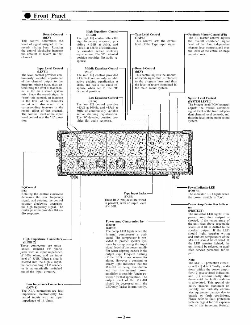
Reverb Control(REV)
This control determines thelevel of signal assigned to thereverb mixing buss. Rotatingthe control clockwise increasethe amount of reverb in thatchannel.
High Equalizer Control(HIGH)
The high EQ control alters thehigh frequency response, pro-viding ±13dB at 5kHz, and±15dB at 15kHz of continuous-ly variable active shelvingequalization. The "0" detentedposition provides flat audio re-sponse.
Middle Equalizer Control(MID)
The mid EQ control provided±15dB of continuously variableactive peaking equalization at2kHz, and has a flat audio re-sponse when set to the "0"detented position.
Input Level Control(LEVEL)
The level control provides con-tinuously variable adjustmentof the channel output to theprogram mixing buss, thus de-termining the level of that chan-nel in the main sound systemmix. Since the reverb signal is"post" this control, an increasein the level of the channel'soutput will also result in acorresponding increase in thereverb effect of that channel.The nominal level of the inputlevel control is at the "10" posi-tion.
Tape Level Control(TAPE)This control sets the overalllevel of the Tape input signal.
Reverb Control(REV)This control adjusts the amountof reverb signal that is returnedto the program buss and thusthe level of reverb contained inthe main sound system.
Foldback Master Control (FB)The FB master control adjuststhe overall combined signallevel of the four independentchannel level controls, and thusthe level of the entire on-stagemonitor mix.
System Level Control(SYSTEM LEVEL)The System level (PGM) controladjusts the overall combinedsignal level of the four indepen-dent channel level controls, andthus the level of the main soundsystem.
Low Equalizer Control(LOW)
The low EQ control provides±13dB at 100Hz, and ±15dB at50Hz of continuously variableactive shelving equalization.The "0" detented position pro-vides flat audio response.
EQ Control(EQ)Rotating the control clockwisedecreases the low frequencysignal, and rotating the controlcounter clockwise decreasesthe high frequency signal. Thecenter position provides flat au-dio response.
Tape Input Jacks(TAPE)
These RCA pin jacks are wiredin parallel, with an input levelof -10dB.
Power Indicator LED(POWER)The indicator LED lights whenthe power switch is "on".
Power Amp Protection Indica-tor(PROTECT)The indicator LED lights if thepower amplifier output isshorted, if the temperature ofthe unit rises above acceptablelevels, or if DC is drifted to thespeaker output. If the LEDshould light, speaker wiringand ambient temperature of theMX-101 should be checked. Ifthe LED remains lighted, theunit should be referred to qual-ified service personnel for re-pair.
High Impedance Connectors(HIGH Z)
These connectors are unba-lanced, standard 1/4" phonejacks with an input impedanceof 100k ohms, and an inputlevel of -35dB. When a plug isinserted into the high-Z input,the coresponding XLR connec-tor is automatically switchedout of the input circuitry.
Power Amp Compression In- dicator(COMP)The comp LED lights when theinternal compressor is acti-vated. The compressor is pro-vided to protect speaker sys-tems by compressing the inputsignal level of the power ampli-fier when clipping occurs in theoutput stage. Frequent flashingof the LED is not reason foralarm. However a constant orsteady light indicates that theMX-101 is being over-drivenand that the internal poweramplifier is possibly "under po-wered" for that application. Theoutput level of the MX-101should be decreased until theLED only flashes intermittently.
Low Impedance Connectors(LOW Z)
The XLR connectors are lowimpedance, electronically ba-lanced inputs with an inputimpedance of 1k ohms.
Note:The MX-101 protection circuit-ry will (1) detect 'faulty condi-tions' within the power ampli-fier, (2) give a visual indication,and (3) automatically shutdown until the fault conditionis alleviated. This special cir-cuitry ensures maximum re-liability and virtually elimin-ates equipment damage due tounsafe or fault conditions.Please refer to fault protectiontable on page 4 for full explana-tion of this important feature.
— 3 —
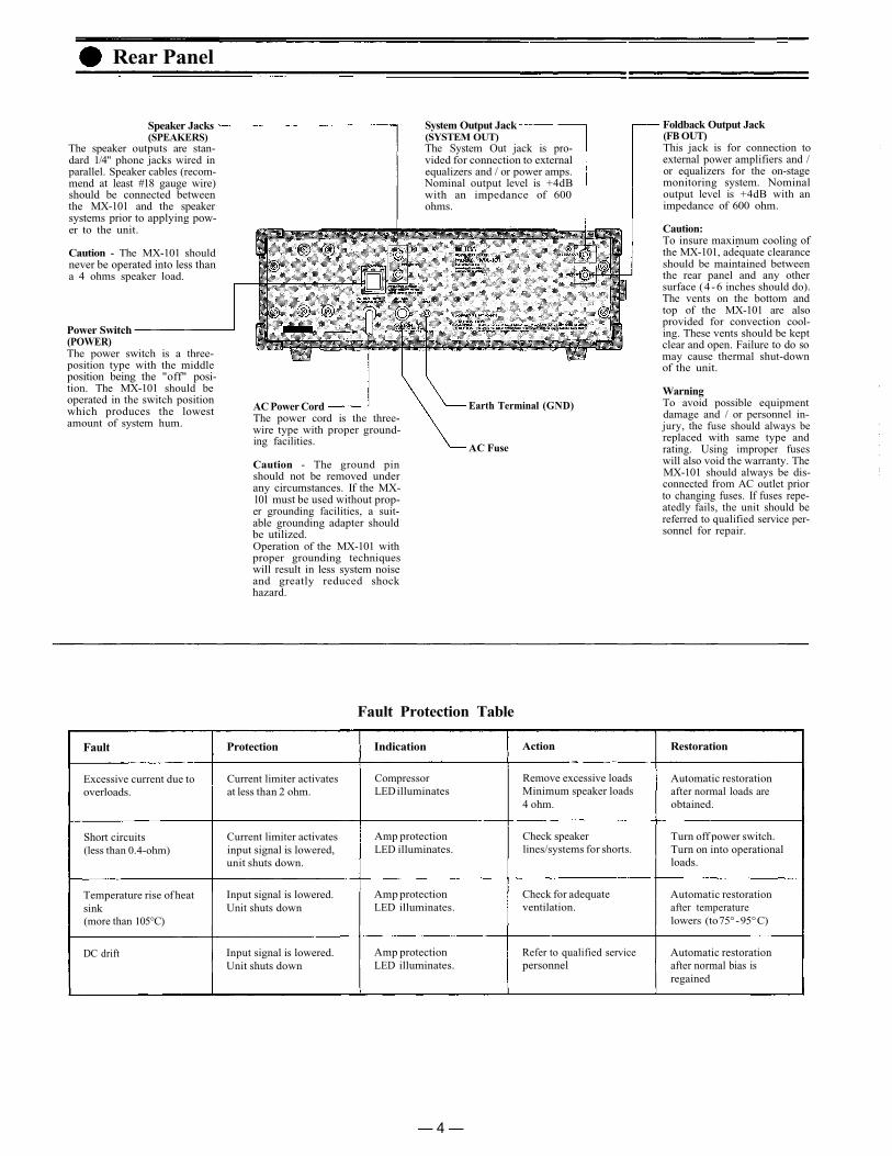
Rear Panel
Speaker Jacks(SPEAKERS)
The speaker outputs are stan-dard 1/4" phone jacks wired inparallel. Speaker cables (recom-mend at least #18 gauge wire)should be connected betweenthe MX-101 and the speakersystems prior to applying pow-er to the unit.
System Output Jack(SYSTEM OUT)The System Out jack is pro-vided for connection to externalequalizers and / or power amps.Nominal output level is +4dBwith an impedance of 600ohms.
Caution - The MX-101 shouldnever be operated into less thana 4 ohms speaker load.
Foldback Output Jack(FB OUT)This jack is for connection toexternal power amplifiers and /or equalizers for the on-stagemonitoring system. Nominaloutput level is +4dB with animpedance of 600 ohm.
Caution:To insure maximum cooling ofthe MX-101, adequate clearanceshould be maintained betweenthe rear panel and any othersurface (4 -6 inches should do).The vents on the bottom andtop of the MX-101 are alsoprovided for convection cool-ing. These vents should be keptclear and open. Failure to do somay cause thermal shut-downof the unit.
Power Switch(POWER)The power switch is a three-position type with the middleposition being the "off" posi-tion. The MX-101 should beoperated in the switch positionwhich produces the lowestamount of system hum.
AC Power CordThe power cord is the three-wire type with proper ground-ing facilities.
Earth Terminal (GND)
AC Fuse
Caution - The ground pinshould not be removed underany circumstances. If the MX-101 must be used without prop-er grounding facilities, a suit-able grounding adapter shouldbe utilized.Operation of the MX-101 withproper grounding techniqueswill result in less system noiseand greatly reduced shockhazard.
WarningTo avoid possible equipmentdamage and / or personnel in-jury, the fuse should always bereplaced with same type andrating. Using improper fuseswill also void the warranty. TheMX-101 should always be dis-connected from AC outlet priorto changing fuses. If fuses repe-atedly fails, the unit should bereferred to qualified service per-sonnel for repair.
Fault Protection Table
Fault
Excessive current due tooverloads.
Short circuits(less than 0.4-ohm)
Temperature rise of heatsink(more than 105°C)
DC drift
Protection
Current limiter activatesat less than 2 ohm.
Current limiter activatesinput signal is lowered,unit shuts down.
Input signal is lowered.Unit shuts down
Input signal is lowered.Unit shuts down
Indication
CompressorLED illuminates
Amp protectionLED illuminates.
Amp protectionLED illuminates.
Amp protectionLED illuminates.
Action
Remove excessive loadsMinimum speaker loads4 ohm.
Check speakerlines/systems for shorts.
Check for adequateventilation.
Refer to qualified servicepersonnel
Restoration
Automatic restorationafter normal loads areobtained.
Turn off power switch.Turn on into operationalloads.
Automatic restorationafter temperaturelowers (to 75° - 95° C)
Automatic restorationafter normal bias isregained
— 4 —
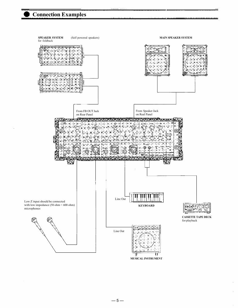
Connection Examples
SPEAKER SYSTEM (Self powered speakers)for foldback
MAIN SPEAKER SYSTEM
From FB OUT Jackon Rear Panel
From Speaker Jackon Real Panel
Low Z input should be connectedwith low impedance (50 ohm ~ 600 ohm)microphones
Line Out
KEYBOARD
CASSETTE TAPE DECKfor playback
Line Out
MUSICAL INSTRUMENT
— 5 —
Input Connections
Generally speaking, there are two rules to follow when connecting equipmentoutputs to the inputs of other equipment.
1. Properly match the impedances of the outputs and inputs.2. Connect low impedance outputs to high impedance inputs.
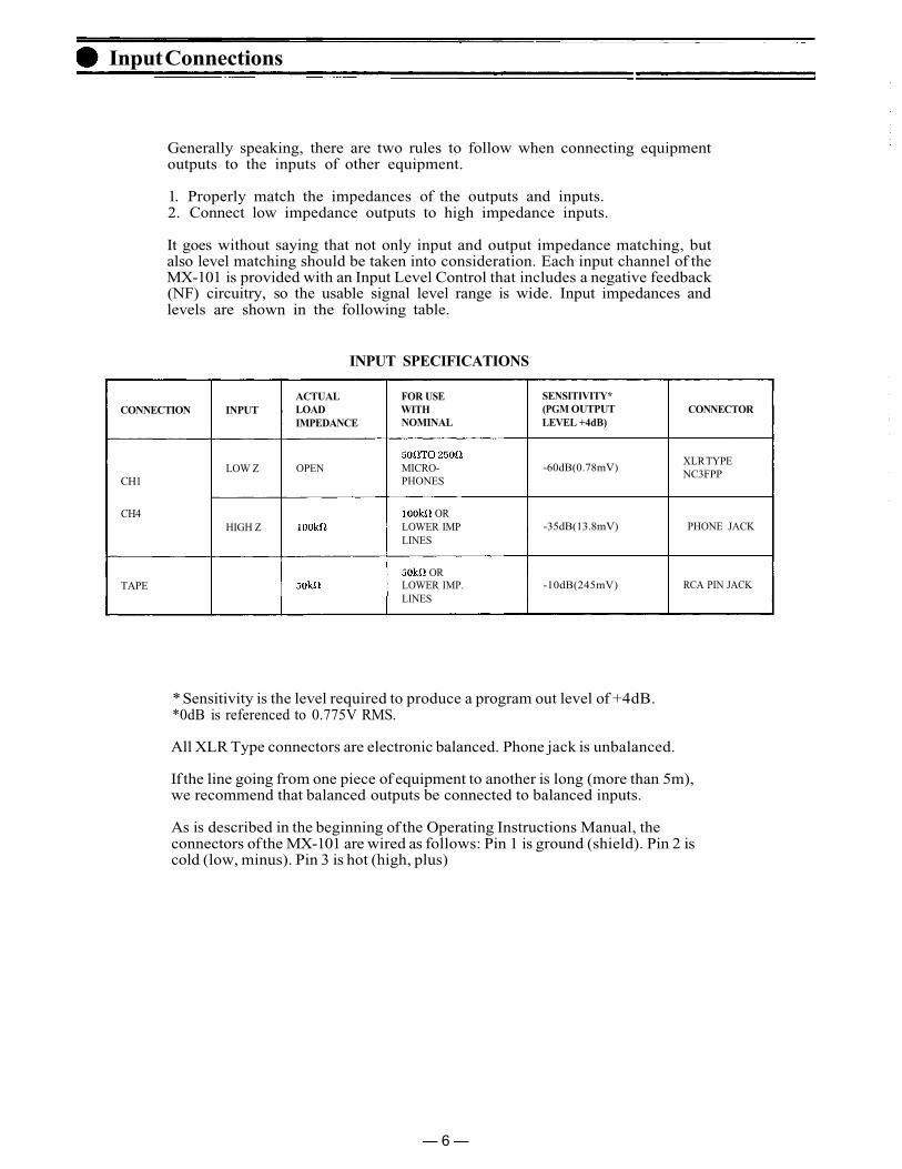
It goes without saying that not only input and output impedance matching, butalso level matching should be taken into consideration. Each input channel of theMX-101 is provided with an Input Level Control that includes a negative feedback(NF) circuitry, so the usable signal level range is wide. Input impedances andlevels are shown in the following table.
INPUT SPECIFICATIONS
CONNECTION
CH1
CH4
TAPE
INPUT
LOW Z
HIGH Z
ACTUALLOADIMPEDANCE
OPEN
FOR USEWITHNOMINAL
MICRO-PHONES
ORLOWER IMPLINES
ORLOWER IMP.LINES
SENSITIVITY*(PGM OUTPUTLEVEL +4dB)
-60dB(0.78mV)
-35dB(13.8mV)
-10dB(245mV)
CONNECTOR
XLR TYPENC3FPP
PHONE JACK
RCA PIN JACK
* Sensitivity is the level required to produce a program out level of +4dB.*0dB is referenced to 0.775V RMS.
All XLR Type connectors are electronic balanced. Phone jack is unbalanced.
If the line going from one piece of equipment to another is long (more than 5m),we recommend that balanced outputs be connected to balanced inputs.
As is described in the beginning of the Operating Instructions Manual, theconnectors of the MX-101 are wired as follows: Pin 1 is ground (shield). Pin 2 iscold (low, minus). Pin 3 is hot (high, plus)
— 6 —
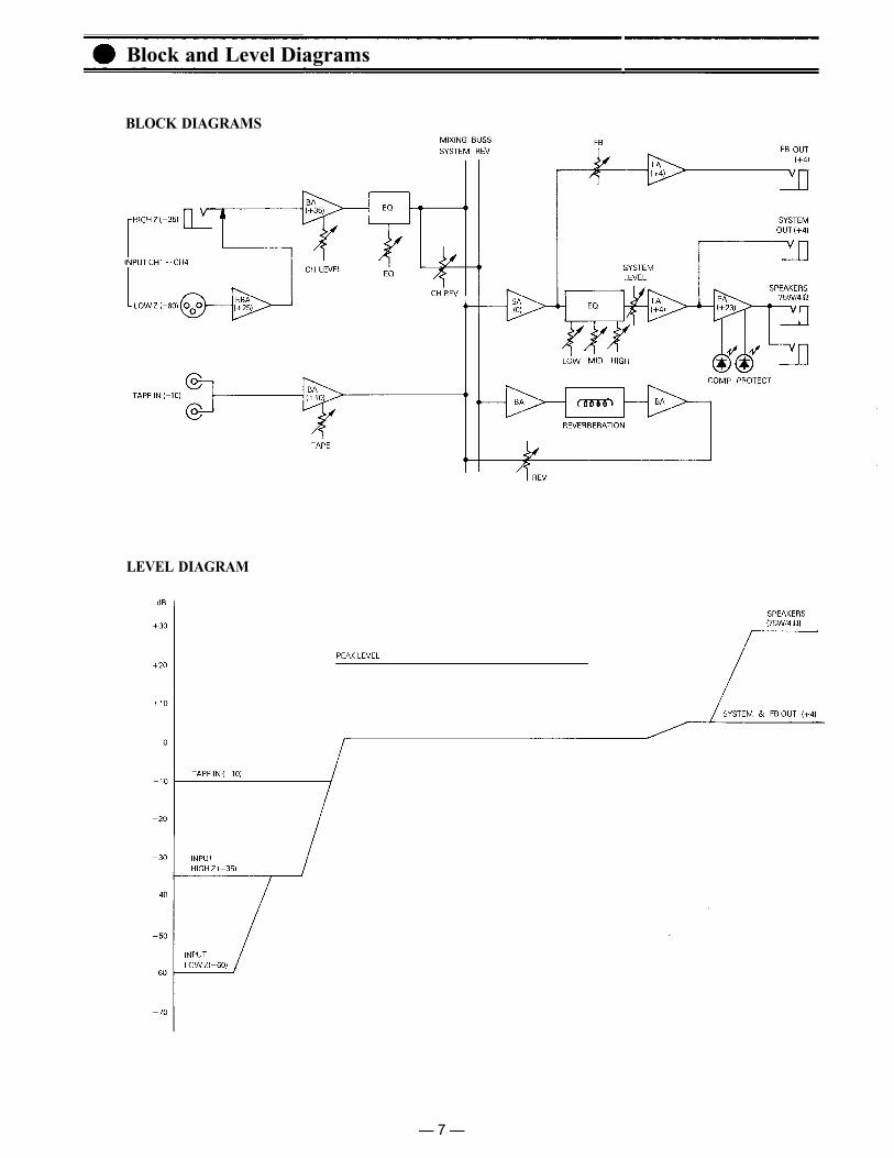
Block and Level Diagrams
BLOCK DIAGRAMS
LEVEL DIAGRAM
— 7 —

Specifications
MIXER SECTION
Frequency Response+ 1, -3dB 30Hz~20kHz (input LEVEL at "5" position)
Total Harmonic Distortion0.05% +4dB* at 1kHz.
Hum and Noise (Open)Equivalent Input Noise
Equivalent Input NoiseAll level Controls MinimumSYSTEM Master at MAX and all
input level controls minimumSYSTEM Master at MAX and one
input level control at Max
-132dB* (20Hz~20kHz)-134dB* (IHFA)-105dB* (IHFA)-87dB* (IHFA)
-70dB* (IHFA)
Maximum Voltage GainINPUT to SYSTEM outINPUT to FB outTAPE to SYSTEM out
Equalization50Hz ±15dB Shelving2kHz ±15dB Peaking15kHz ±15dB Shelving
INPUT SPECIFICATIONS
CONNECTION
CH1
CH4
TAPE
INPUT
LOW Z
HIGH Z
ACTUALLOADIMPEDANCE
OPEN
FOR USEWITHNOMINAL
MICRO-PHONES
ORLOWER IMPLINES
ORLOWER IMPLINES
SENSITIVITY*(PGM OUTPUTLEVEL +4dB)
-60dB(0.78mV)
-35dB(13.8mV)
-10dB(245mV)
CONNECTOR
XLR TYPE
PHONE JACK
RCA PIN JACK
OUTPUT SPECIFICATIONS
CONNECTION
SYSTEM
FB
ACTUALSOURCEIMPEDANCE
FOR USE WITHNOMINAL
OR HIGHERIMP LINES
OR HIGHERIMP LINES
OUTPUT LEVEL*
NOMINAL
+4dB(1.23V)
+4dB(1.23V)
MAX BEFORECLIP
+ 20dB(7.75V)
+ 20dB(7.75V)
CONNECTOR
PHONE JACK
PHONE JACK
POWER AMPLIFIER SECTIONFrequency Response
+ 0 -1dB 15Hz to 30kHz (75 W RMS )Rated Power & Load
75W RMS 57W RMSPower Output at Clipping
1% THD. 1kHz80W RMS 60W RMS
Total Harmonic DistortionLess than 0.1% (100mW~75W RMS. 20Hz~20kHz.Typically below 0.05%
Compresser Dynamic RangeGreater than 26dB
Hum and NoiseAt least 100dB S/N ratio. 20Hz~20kHzAt least 108dB S/N ratio IHF-A weighted
Damping Factor200 (1kHz
Output ConnectorPhone Jack × 2
Power Requirement182 W
Dimensions460(W) × 171(H) × 248(D) (18.11 × 6.73 × 8.91) ins.
Weight7.5 Kg (16.5 Ibs)
*0dB is referenced to 0.775V RMS.
*Specifications are subject to change without notice.
64dB64dB14dB
— 8 —
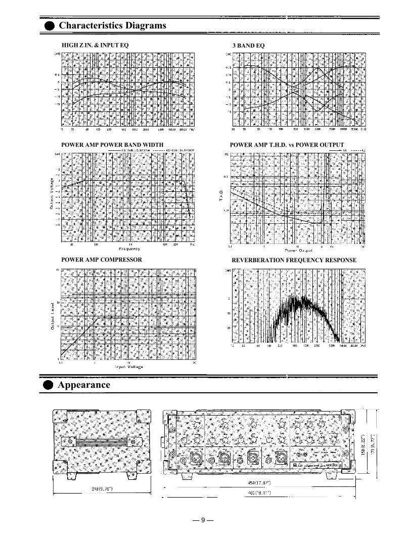
Characteristics Diagrams
HIGH Z IN. & INPUT EQ 3 BAND EQ
POWER AMP POWER BAND WIDTH POWER AMP T.H.D. vs POWER OUTPUT
POWER AMP COMPRESSOR REVERBERATION FREQUENCY RESPONSE
Appearance
— 9 —

Toa Electric Co., Ltd.KOBE, JAPAN
Printed in Japan133-02-884-9