operating different displays in military fast jets using
TRANSCRIPT

Available online at http://docs.lib.purdue.edu/jate
Journal of Aviation Technology and Engineering 8:1 (2018) 31–50
Operating Different Displays in Military Fast Jets Using Eye Gaze Tracker
Jeevitha Shree DV, L. R. D. Murthy, Kamalpreet Singh Saluja, and Pradipta Biswas
Indian Institute of Science
Abstract
This paper investigated the use of an eye-gaze-controlled interface in a military aviation environment. We set up a flight simulator andused the gaze-controlled interface in three different configurations of displays (head down, head up, and head mounted) for military fastjets. Our studies found that the gaze-controlled interface statistically significantly increased the speed of interaction for secondary missioncontrol tasks compared to touchscreen- and joystick-based target designation system. Finally, we tested a gaze-controlled system inside anaircraft both on the ground and in different phases of flight with military pilots. Results showed that they could undertake representativepointing and selection tasks in less than two seconds, on average.
Keywords: gaze-controlled interface, flight simulator, adaptive MFD, eye-gaze tracker, aviation UI
Introduction
Advancement of sensor and communication technologies has made aviation easier and safer at a cost of generating a hugeamount of information from aircraft. Although a good amount of information is used for offline processing on the groundor automated processing by mission computers on board, like controlling the autopilot system, pilots need to manuallyperceive and process a plethora of information for decision making for both flying and mission control tasks (Hierl,Neujahr, & Sandl, 2012). Information processing is more difficult in military fast jets (fighter aircraft used for air superiorityor multirole missions) than passenger aircraft as pilots need to undertake secondary mission tasks in addition to the primaryflying task. Secondary mission control tasks may include reconnaissance, protecting or tracking airborne assets, and weapondelivery, all of which require careful perception and analysis of information outside the aircraft as well as informationdisplayed in the cockpit. Efficiently displaying information inside the limited space of the cockpit is a challenging designtask. Existing military aircraft use three types of visual display: head-down display (HDD), head-up display (HUD), andhead-mounted display (HMD).
HDDs are configured to display information as multifunction displays (MFDs). MFDs are used for showing informationranging from primary flight data to details of airborne objects in a configurable way. Each is rectangular in shape, consistsof a set of soft buttons on the periphery, and a graphical user interface (GUI) in the middle. MFDs can present data inmultiple pages, rather than always being present at once like analog displays and so consumes less space in a cockpitcompared to analog displays.
HUDs are placed in the line of sight of the pilot, collimated at infinity to reduce parallax error (Wood & Howells, 2001).HUDs show primary flight information like speed, altitude, azimuth level, and airbourne targets. HUDs do not directly take
http://dx.doi.org/10.7771/2159-6670.1184

input from users like MFDs but update information
appropriately as the aircraft is operated.
HDDs and HUDs are fixed in place in the cockpit whileHMDs are projected from the helmet and pilots can getinformation even if they are not looking straight ahead.HMDs work like an augmented reality system. Pilots do notloose situational awareness when using HMDs; they cansee through the display while it displays extra informationon primary flight parameters and airborne objects in a see-through display.
In terms of taking input from users, HDDs are operatedusing physical touch and target designation system (TDS),which is a joystick attached to the throttle (Eurofighter,2017). Recently, voice commands (Hierl et al., 2012) werealso used by uttering the caption on buttons. HMDs are alsooperated using the TDS.
Existing military aircraft have multiple HDDs and physi-cally touching an MFD in an HDD with gloves may oftenbecome difficult for small targets (Hierl et al., 2012). TheTDS can be improved by reducing the pointing time (thetime needed to bring a cursor on a screen element). Targetprediction algorithms, which require a priori location oftargets on screen (Dixon, Fogarty, & Wobbrock, 2012),cannot be used for MFDs as targets may appear anywhere onthe GUI part (here the GUI part indicates the portion of theMFD between the peripheral Bessel keys). There are alsolimited interaction modalities available as pilots find itdifficult to take their hands away from throttle and flightstick in high-G manoeuvers (Hierl et al., 2012). Direct voiceinput has already been tested in military aviation, althoughvoice recognition systems are challenging for non-nativeEnglish speakers and for countries having multiple languagespeakers (Biswas & Langdon, 2015; Hierl et al., 2012).
This paper proposes the use of an eye gaze controlsystem to improve existing TDSs. Operators have to look atvarious displays to process information such as investigat-ing positions of airborne targets with an MFD or an HMDor changing pages of an MFD. We propose leveraging thiseye gaze as a direct way of controlling pointer movementson an MFD and an HMD as opposed to touchscreen orHOTAS (hands on throttle and stick) thumbstick. Eye gazetrackers as direct controllers of pointer movement have notyet been widely tested in the military aviation environment.De Reus, Zon, and Ouwerkerk (2012) reported qualitativedata on using a gaze-controlled interface in a helmet but didnot specify the accuracy of the gaze tracker or any quanti-tative data on processing speed of information. Accordingto TopGunMilitary (2013), the gaze control system of theM-TADS system in Apache AH-64 attack helicoptersallows the pilot to aim his or her weapon systems by merelylooking at the desired target.
We tested an eye-gaze-controlled interface with a flightsimulator and proposed a couple of adaptation algorithmsfor gaze-controlled displays. Our algorithm significantlyreduced pointing and selection times for large peripheral
buttons as well as improved flying performance for thegaze-controlled system compared to touchscreen for repre-sentative flying and pointing and selection tasks.
We also investigated using MFDs in HUD instead ofHDD and designed a frugal eye-gaze-controlled HUD. Ourproposed algorithms significantly reduced pointing timeand improved flying performance in terms of deviationfrom flight envelope compared to an existing TDS inrepresentative dual task studies described later.
Finally, we used a wearable gaze tracker and simulated acase study of operating an HMD using gaze tracking. Wenoted a one-third decrease in pointing and selection timesfor a gaze-controlled system compared to a traditional TDS.The main contributions of the paper are
1. Integrating and exploring an eye-gaze-controlledinterface for a flight simulator.
2. Proposing new algorithms to improve pointing andselection times in a gaze-controlled interface.
3. Designing and evaluating gaze-controlled HUD andsimulated HMD displays.
The paper is organized as follows. Section 2 presentsrelated literature on gaze-controlled interface and pointingfacilitation systems. Sections 3 describes our flight simu-lator setup followed by a couple of pilot studies involving amilitary aircraft and high-end third party simulator inSection 4. Sections 5 to 8 present three user studies usingour flight simulator setup and a study conducted in anaircraft both on the ground and in the air. Section 9 presentsa general discussion followed by concluding remarks inSection 10.
Related Work
Eye tracking is the process of measuring either the pointof gaze (where one is looking) or the motion of an eyerelative to the head. An eye tracker is a device for mea-suring eye positions and eye movement. Although researchon eye tracking dates back to the early 20th century (Huey,1908), controlling a display with gaze tracking is arelatively new concept. Eye-gaze-controlled interfaces weremainly explored as assistive technology for people withsevere motor impairment. However, using eye tracking insituational impairment poses new challenges in terms ofspeed and accuracy. A detailed survey on gaze-controlledinterfaces can be found elsewhere (Biswas & Langdon,2015; Biswas, Prabhakar, Rajesh, Pandit, & Halder, 2017;Zhai, Morimoto, & Ihde, 1999). Existing research on com-paring eye-gaze-controlled interfaces with other modalitiesis mainly limited to desktop computing and, excepta few cases involving novice users (Biswas & Langdon,2014), generally traditional input devices like mouse ortouchscreen worked better than gaze-controlled systems(Vertegaal, 2008; Ware & Mikaelian, 1987). A few recentstudies on automotive user interfaces found gaze-controlled
32 Biswas P. et al / Journal of Aviation Technology and Engineering

interfaces worked worse than (Poitschke, Laquai, Stamboliev,& Rigoll, 2011) or similar to (Biswas et al., 2017) touchscreenin terms of pointing and selection times although with higherrate of errors.
Researchers have already explored various target predic-tion or intent recognition techniques for reducing pointingtimes. Most of these techniques continuously record velocity,acceleration, and bearing of cursor movement, fit differentmodels, and use that model to predict either the cursormovement or the target itself (Murata, 1998; Pasqual &Wobbrock, 2014; Ruiz & Lank, 2010). However, eye gazemovements are not as smooth as mouse, finger, or handmovements, but rather follow a ‘‘spotlight’’ metaphor andso far no next point or target prediction models have beentested for gaze-controlled interfaces. A backpropagationneural network model was used (Biswas & Langdon, 2015),but only to differentiate between ballistic and homingmovements. Farrell and Zhai (2005) noted that ‘‘humans usetheir eyes naturally as perceptive, not manipulative, bodyparts. Eye movement is often outside conscious thought,and it can be stressful to carefully guide eye movement asrequired to accurately use these target selection systems.’’Gaze tracking is used for zooming or accentuating part of adisplay to help pointing by another pointing modality (Jacob,Hurwitz, & Kamhi, 2013, Pfeuffer & Gellersen, 2016; Zhaiet al. 1999).
In the military aviation domain, the United States AirForce (Furness, 1986) idealized a ‘‘Super Cockpit,’’ ageneric crew station that would conform to operators’ naturalperceptual, cognitive, and motor capabilities. Technologieswere envisaged that would provide the means to createvirtual worlds with visual and auditory fidelity, and perceiveoperators’ interactions using cognitively simpler, ‘‘biocyber-netics’’ control inputs. In recent times, a similar concept wasconsidered by BAE Systems (2018) as a sixth-generationcockpit that will use the latest AR/VR technologies withhead tracking and gesture recognition features. None of theseidealized models considered the gaze-controlled interface.To date, aircraft use hardware switches, joysticks, auditoryfeedback, and small-screen displays (primary flight displayor MFD) as main input and output modalities. Recently,touchscreen displays and head trackers have also beenexplored in fighter aircraft. Thomas, Biswas, and Langdon(2015) listed all input and output modalities used in a fewmodern fighter aircraft. Grandt, Pfendler, and Mooshage(2013) compared trackball, touchscreen, speech input, andmouse for an anti-warfare system; however, the experimentalset up was similar to a desktop computing environment withpointing and selection as the only task to be undertaken.Thomas (2018) reported results from ISO 9241 taskinvolving thumbstick, trackball, touchpad, and touchscreenand found trackpad to be most accurate and argued forsupporting new modalities for HOTAS cursor controldevice. Biswas and Langdon (2015) reported a significantreduction in reaction time for a gaze-controlled interface
compared to HOTAS TDS for operating a simulatedMFD. However, that study did not involve any primaryflying task and was configured in a desktop computingenvironment.
Gaze-controlled interface has also been explored forvirtual and augmented reality systems. Commercial eyegaze trackers have been integrated with virtual realitysystems (Ergoneers, 2018; Tobii, 2018b). For augmentedreality-based systems, researchers mainly explored detec-tion of eye gaze, but the resulting gaze tracking system isnot as accurate as existing commercial systems (Handa &Ebisawa, 2008; Plopski et al., 2015). For example, Handaand Ebisawa (2008) measured accuracy only with fixedhead position and reported results only in terms of ninepoints on screen, while commercial wearable gaze trackers(Tobii, 2018a) have accuracy at 0.5˚ of visual angle.Existing HMDs like the BAES StrikerH II system (Striker,2018) works based on head tracking and augmented reality.It augments pilot vision with extra information in see-through display: the head trackers are used to put thedisplay in a pilot’s visual field. HMDs display weaponryinformation and airborne objects and need actuation from aHOTAS stick to select the appropriate weapon to engage.This paper explored if one can use a commercial wearablegaze tracker as a cursor control device, thus eliminatingHOTAS-based actuation for operating HMDs.
Flight Simulator Setup
We designed a flight simulator to conduct studies in dualtask settings involving gaze-controlled interfaces. Usingour setup, participants undertook standard flying tasks inparallel with representative pointing and selection tasks.This setup allowed us to measure not only pointing andselection times, but also the total response time, consistingof the time required to switch from primary flying to sec-ondary mission control tasks. We set up the flight simulatorwith both HDD and an interactive HUD. Existing high-endsimulators are meant for pilot training purposes and do notallow configuring MFDs to explore different adaptationstrategies due to software integration, time duration, andsecurity reasons. They also do not have any interactiveHUDs. To our knowledge, no HUDs from either theautomotive or aviation domain take input from users; theyare only used to display primary flight information. Weexplored the possibility of displaying MFD at the samevisual line of sight of pilots’ normal seating position, sothat they never need to look down for any information.Presently, HMDs are designed to interact with a displaywithout losing situational awareness (Eurofighter, 2017);our results on HUDs can also be extended for HMDs.
The experimental setup consisted of primary andsecondary displays. The flight simulator was projectedon a screen. The secondary task (described below) wasdisplayed either on an LCD screen or on a projected display
Biswas P. et al / Journal of Aviation Technology and Engineering 33
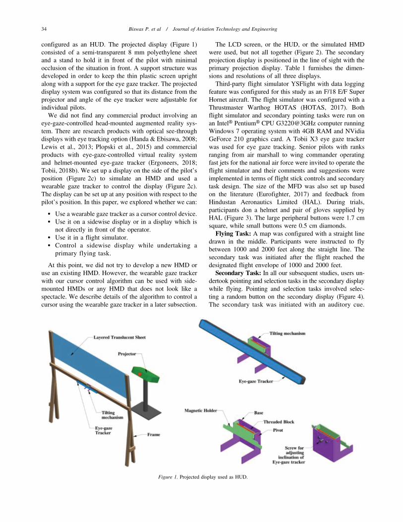
configured as an HUD. The projected display (Figure 1)consisted of a semi-transparent 8 mm polyethylene sheetand a stand to hold it in front of the pilot with minimalocclusion of the situation in front. A support structure wasdeveloped in order to keep the thin plastic screen uprightalong with a support for the eye gaze tracker. The projecteddisplay system was configured so that its distance from theprojector and angle of the eye tracker were adjustable forindividual pilots.
We did not find any commercial product involving aneye-gaze-controlled head-mounted augmented reality sys-tem. There are research products with optical see-throughdisplays with eye tracking option (Handa & Ebisawa, 2008;Lewis et al., 2013; Plopski et al., 2015) and commercialproducts with eye-gaze-controlled virtual reality systemand helmet-mounted eye-gaze tracker (Ergoneers, 2018;Tobii, 2018b). We set up a display on the side of the pilot’sposition (Figure 2c) to simulate an HMD and used awearable gaze tracker to control the display (Figure 2c).The display can be set up at any position with respect to thepilot’s position. In this paper, we explored whether we can:
N Use a wearable gaze tracker as a cursor control device.N Use it on a sidewise display or in a display which is
not directly in front of the operator.N Use it in a flight simulator.N Control a sidewise display while undertaking a
primary flying task.
At this point, we did not try to develop a new HMD oruse an existing HMD. However, the wearable gaze trackerwith our cursor control algorithm can be used with side-mounted HMDs or any HMD that does not look like aspectacle. We describe details of the algorithm to control acursor using the wearable gaze tracker in a later subsection.
The LCD screen, or the HUD, or the simulated HMDwere used, but not all together (Figure 2). The secondaryprojection display is positioned in the line of sight with theprimary projection display. Table 1 furnishes the dimen-sions and resolutions of all three displays.
Third-party flight simulator YSFlight with data loggingfeature was configured for this study as an F/18 E/F SuperHornet aircraft. The flight simulator was configured with aThrustmaster Warthog HOTAS (HOTAS, 2017). Bothflight simulator and secondary pointing tasks were run onan IntelH PentiumH CPU G3220@3GHz computer runningWindows 7 operating system with 4GB RAM and NVidiaGeForce 210 graphics card. A Tobii X3 eye gaze trackerwas used for eye gaze tracking. Senior pilots with ranksranging from air marshall to wing commander operatingfast jets for the national air force were invited to operate theflight simulator and their comments and suggestions wereimplemented in terms of flight stick controls and secondarytask design. The size of the MFD was also set up basedon the literature (Eurofighter, 2017) and feedback fromHindustan Aeronautics Limited (HAL). During trials,participants don a helmet and pair of gloves supplied byHAL (Figure 3). The large peripheral buttons were 1.7 cmsquare, while small buttons were 0.5 cm diamonds.
Flying Task: A map was configured with a straight linedrawn in the middle. Participants were instructed to flybetween 1000 and 2000 feet along the straight line. Thesecondary task was initiated after the flight reached thedesignated flight envelope of 1000 and 2000 feet.
Secondary Task: In all our subsequent studies, users un-dertook pointing and selection tasks in the secondary displaywhile flying. Pointing and selection tasks involved selec-ting a random button on the secondary display (Figure 4).The secondary task was initiated with an auditory cue.
Figure 1. Projected display used as HUD.
34 Biswas P. et al / Journal of Aviation Technology and Engineering

On hearing a beep sound, participants were instructed toundertake one button selection task on the secondary displayand then switch their attention back to flying until they heardthe next auditory cue (beep sound).
N For HDD and HUD, we rendered an MFD on thesecondary display. The MFD consisted of 17 peripheralbuttons and 10 small buttons at the central GUI part.Users needed to select one of these 27 buttons.
N For HMD, we rendered only five small buttons in asky-colored background and users needed to selectone of these five buttons.
Target Designation System: A joystick on the throttleof the HOTAS was configured as the TDS. For gaze-controlled interface, the TDS was only used for selection,not for moving the pointer on the MFD.
Eye-Gaze-Controlled HDD
In the following subsections, we describe a set of intel-ligent algorithms used to control a GUI with eye gazetracker and facilitate pointing and selection tasks forvarious aviation displays.
Controlling GUI through screen-mounted eye gazetracker: After developing the flight simulator, we devel-oped the following algorithm for controlling an on-screencursor using a screen-mounted eye gaze tracker. Retinalganglion cells only respond to change in stimuli, and evenif eye gaze is focused at a point, microsaccadic eye gazemovements always change the gaze location around thepoint of interest. Due to these microsaccadic eye gazemovements, the raw output from any eye gaze tracker cannotbe used to control an on-screen pointer and it requiresfiltering to stabilize the cursor. Our gaze tracking systemrecords the eye gaze positions continuously (see Figure 5,point A) and takes the median of the pixel locations in every250 ms (minimum duration of a saccade) to estimate theregion of interest or saccadic focus points (point B infigure 5). The median was less susceptible to outliers thanthe arithmetic mean in the case where the eye gaze trackerbriefly lost signal. We simulate the eye movement using aBezier curve that smooths the cursor movement bet-ween two focus points as we wanted to make the cursormovement look like an existing TDS. It then pushes thefocus points into a stack and the Bezier curve (Salomon,2005) algorithm interpolates points between the two focuspoints (see Figure 5, point B). The pointer is drawn ateach interpolated point in every 16 ms to visualize asmooth on-screen movement (see Figure 5, point C). Foradaptive conditions, it activates or enlarges the on-screentarget nearest to the present gaze location (see Figure 5,point C). Using this algorithm, we can produce a smoothcursor trajectory through the otherwise jittery eye gazemovements.
Adaptation for Large Buttons of an MFD: In userstudies involving the gaze-controlled interface, we notedthat as users stare at the middle of the target, due to theinaccuracy of the tracker or their head movement, theneighboring button was occasionally selected. The prob-ability of wrong selection increases if the buttons are
Figure 2. Flight simulator setup.
Biswas P. et al / Journal of Aviation Technology and Engineering 35

closely spaced in the interface. Hence, the probability ofwrong selection will be reduced if we can increase theinter-button spacing. However, we cannot change thedesign of an interface like an existing MFD just to make aninteraction technique work better.
We have explored the option of introducing hotspotsinside each button to facilitate eye gaze tracking interac-tion. If we can introduce a hotspot on each button and keepthem well separated, we can instruct users such that the firstsaccade on a button would launch on these hotspots. We
hypothesize that keeping these hotspots well separated willreduce pointing times and chances of wrong selection.
To find the best position of hotspots, we represented aninterface as a graph where each node corresponds to atarget button (clickable objects) and neighboring buttonsare connected by an edge. We assumed each button has ahotspot on it, which is initially located at the center of thebutton. The weight of each edge is equal to the Euclidiandistance between the hotspots of two neighboring buttons.We explored two different algorithms to increase the
Table 1Specifications of displays.
Primary displaySecondary display
for HUDSecondary display
for HDDSecondary display
for HMD
Projector/monitor model Dell 1220 Acer X1185G Waveshare 10.10 LCD Acer X1185GResolution (pixel) 1024 6 768 1024 6 768 1280 6 800 1024 6 768Size of projection/monitor (mm) 1200 6 900 380 6 295 250 6 167 380 6 295Distance from eye (mm) 2100 285 280 813
Figure 3. Instruments used in flight simulator.
36 Biswas P. et al / Journal of Aviation Technology and Engineering

distances between hotspots. We defined the following costfunction and tried to minimize it:
Cost function~X
Vdij
1
d2ij
, ð1Þ
where dij is the distance of the hotspots between buttons iand j and is equal to the weight of the edge between nodes iand j.
We have modeled the problem of finding optimumlocations of hotspots as a state space search problem. Eachstate corresponds to a particular organization of hotspots.
A state transition occurs when any hotspot changes itsposition. If we consider each button has k possible positionsand if an interface has n buttons, then an exhaustive searchalgorithm is needed to evaluate kn states. Even for a mode-rately complex interface, an exhaustive search algorithmwill be computationally intensive or almost impossible.Hence, we used the following two algorithms.
Greedy Algorithm: This algorithm picks the edge withminimum weight, which means the two most closelyspaced buttons. It checks the degrees of the two nodes ofthe minimum-weight edge and updates the hotspot of the
Figure 4. Screenshot of secondary tasks.
Figure 5. Cursor control through eye gaze.
Biswas P. et al / Journal of Aviation Technology and Engineering 37

node with higher degree. The algorithm calculates thecentroid of the hotspots of neighboring nodes of the selectednode and the new hotspot is calculated as the nearest pointon the selected button (or node) to the centroid. Whileselecting the next node for updating hotspot, the algorithmchecks whether the node was visited earlier and, if so, itselects a different node. The algorithm is greedy in the sensethat it only updates the hotspot if the overall value of the costfunction is reduced from the previous value.
Simulated Annealing: This algorithm randomly selectsa node and also randomly selects a point on the node as itsnew hotspot. If the new hotspot reduces the value of the costfunction, then it is selected and updated. However, even ifthe new hotspot increases the value of the cost function, itmay still be selected based on the following condition:
eðoldCostFn{newCostFnÞ
Tw a random number
between 0 and 1 ð1Þ
In the above equation, the value of T runs from 5000 to 1and is reduced by 1 in each iteration.
We have tested the algorithm on a sample MFD andtested the algorithms multiple times with different initialpositions of the hotspots. It may be noted that bothalgorithms reduced the cost function and increased theoverall weight of edges (Figure 6). The simulated anneal-ing algorithm reduced the cost function further than thegreedy algorithm. The greedy algorithm was stuck in cycleand a local optimum after visiting all nodes a couple oftimes. The simulated annealing algorithm can overcome alocal optimum due to randomly choosing node and hot-spots, although we also could not conclude whether itreached the global optimum. It may be noted that the weightsof edges in the final state of simulated annealing weresignificantly lower (t (0,13) 5 3.2, p , 0.01) than those inthe initial state in a paired t-test. Figure 7 shows an exampleof a set of hotspots on a sample MFD. The blue dots onthe buttons are obtained through the simulated annealingalgorithm discussed above.
Adaptation for Small Buttons: The previous strategy ofintroducing hotspots did not work for small buttons used toindicate airborne objects, as the buttons are too small to
hold a hotspot. Additionally, these buttons may appear at ahigher density than the accuracy of an eye gaze tracker.
We developed an adaptive zooming technique to increaseinter-button spacing of densely packed on-screen elements.In desktop computing, zooming a part of a display forreducing pointing times has already been well explored(McGuffin & Balakrishnan, 2005) and for gaze-controlledinterfaces, too (Bates, 1999). In our experimental setup, weused 175% zooming, as it resulted in an inter-button spacingmore than 0.4˚ of visual angle (Figure 8), which was theaccuracy of our eye gaze tracker. In actual implementation,whenever a new target appears, or an existing one changesposition, we calculate the pairwise distance among all pairsof targets and decide the zooming level based on theminimum distance. We implemented the following twotechniques for selecting small targets in the MFD.
Adaptation 1: In this technique, if users click near asmall button, a 250 6 250 pixel area around the buttonenlarges in size. In this experimental setup, we hard-codethe zooming percentage and zooming area, although bothcan be configured dynamically. In the zoomed-in area, anearest neighborhood predictor was implemented: userscould select a target by clicking near the target.
Adaptation 2: This technique was similar to the previoustechnique with one more feature in the implementation of thenearest neighborhood predictor. In this technique, users onlyneed to stare (or look) near the target item and, upondwelling for one second, the target is automatically selected.Additionally, users could also select a target by clicking nearthe target, as in the previous strategy.
In all adaptation strategies, the target button was indi-cated by drawing a yellow ring around it. The yellow ringwas made distinctive so that users did not need to undertakea serial visual search to find the target; rather it was poppedout from background.
The flow chart shown in Figure 9 explains the workingof the adaptive MFD. It may be noted that the adaptationstrategies are developed for a cursor control device, notfor facilitating physical touch in a touchscreen. The blueboxes indicate system-initiated function while brown boxesindicate user-initiated action.
If the cursor moves in the outer region of the MFD(marked in Figure 9), the nearest neighborhood predictorfinds the closest hotspot and activates one of the peripherallarge buttons. Activation is indicated by changing back-ground color and enlarging the target 1.5 times its size. Theuser selects the target by pressing the slew button on thethrottle stick of the HOTAS.
If the cursor moved in the inner region of the MFD, userswere instructed to press the slew button of the HOTASwhen the cursor is on or near one of the small buttons. Ifthe slew button is pressed when the cursor is on the target,it is selected immediately. If the cursor is not on the button,the neighborhood is zoomed in. The user then selects thetarget by bringing the cursor near the target button and thenFigure 6. Comparing state space search algorithms.
38 Biswas P. et al / Journal of Aviation Technology and Engineering

either by pressing the slew button (Adaptation 1) or bystaring in (dwelling, Adaptation 2) near the target button.
Eye-Gaze-Controlled HMD
Controlling GUI through wearable eye gaze tracker:We used a screen-mounted gaze tracker and the previousalgorithm for controlling a display in HDD and HUDconfigurations. However, in HMD configuration we used awearable gaze tracker, as it would not be possible to use ascreen-mounted tracker with an HMD. A screen-mountedgaze tracker can specify eye gaze positions in x and y
coordinates with respect to a screen. However, a wearablegaze tracker generates x and y coordinates in a normalizedform between 0 and 1 covering the entire visual field of anoperator. We mapped the normalized x and y coordinatesinto screen coordinates using a calibration program and abackpropagation neural network. The calibration programdisplays nine dots on a screen at an interval of 2.5 secondsfor displaying each dot. Users were instructed to stare ateach dot. We recorded the normalized coordinates while adot was displayed on screen and stored the median valuesof the normalized coordinates. After the calibration routine,we generated a file that contains the median values of
Figure 7. Hotspots for a representative MFD.
Figure 8. Zooming for small buttons.
Biswas P. et al / Journal of Aviation Technology and Engineering 39

normalized coordinates generated by the gaze tracker andscreen coordinate of the midpoint of each dot.
We collected data from nine participants using the flightsimulator setup shown in Figure 2c and evaluated a linearregression and neural network model for mapping from eyetracker coordinates to screen coordinates. We compared themodels by the R2 and RMS (root mean square) error inprediction. Figure 10 shows the average values and theerror bars indicate the standard deviation. Based on theanalysis, we noted that the neural network model produceshigher R2 and lower RMS values for error and selected theneural network model (Figure 11).
During subsequent studies with eye tracking glasses, weinitially calibrated the tracker by training the neuralnetwork. After the calibration, we recorded the normalizedcoordinates in real time, fed them to the trained network,and drew a cursor on the screen based on the output fromthe neural network. We recorded the nearest target to thecursor location. If we recorded the same target for sevenconsecutive times, we activated it.
Study 1: HDD
This study describes a dual task study using a 100 LCDdisplay for rendering an MFD in head-down configuration.
Participants: We collected data from 12 participants (10male, 2 female; age range 25 to 35 years, average age 28.3years). All participants volunteered for the study and didnot report any problems with the experimental setup duringthe practice session. None of them had used a gaze-controlled interface or the particular flight simulator setupbefore the study. Participants were trained with the flightsimulator: they were selected based upon their performancein maintaining altitude and direction in the flight simulator.
Design: The study was designed as 3 6 2 repeatedmeasure design with the following factors:
N Modality: touchscreen 6 Adaptation 1 6 Adaptation 2.N Button size: large buttons 6 small buttons.
Participants were required to press large and smallbuttons alternately on hearing the auditory cue. Eachparticipant was instructed to press 8 large and 8 smallbuttons alternately. We measured the following dependentvariables:
N Flying performance was measured by
˚ Deviation from the straight line flying path.
˚ Deviation in altitude outside the specified envelopeof 1000 and 2000 feet.
Figure 9. Flow chart of adaptive MFD operation.
40 Biswas P. et al / Journal of Aviation Technology and Engineering

N Pointing and clicking performance was measured as
˚ Response time as the time difference between theauditory cue and the time instant of the selection ofthe target button. This time duration adds up thetime to react to auditory cue, switch from primaryto secondary task, and the pointing and selectiontime in the secondary task.
˚ Error in secondary task as the number of wrongbuttons selected.
N Cognitive load measured using the NASA Task LoadIndex (TLX) score.
N Subjective preference as measured by the SystemUsability Score (SUS) (SUS, 2014).
Procedure: Initially participants were briefed about thepurpose of the study. Then they were trained with the flyingand pointing and selection tasks separately and undertookboth tasks separately. We proceeded with the trial only whenthey could complete each task separately. Finally, they
Figure 10. Comparing linear regression and neural network models for predicting screen coordinates from eye tracking glasses.
Figure 11. Neural network for using eye tracking glass as a cursor control device.
Biswas P. et al / Journal of Aviation Technology and Engineering 41
undertook the dual task study. In this study, we used a clearvisor of the helmet, while a later study separately collecteddata on clear and dark visors. On completion of each con-dition, we recorded the cognitive load and preference usingTLX and SUS questionnaire.
Results: All participants completed the trial in all condi-tions. In total, we recorded 580 pointing tasks, although theydid not select an equal number of buttons in each condition.In the subsequent graphs, error bars represent standarddeviation.
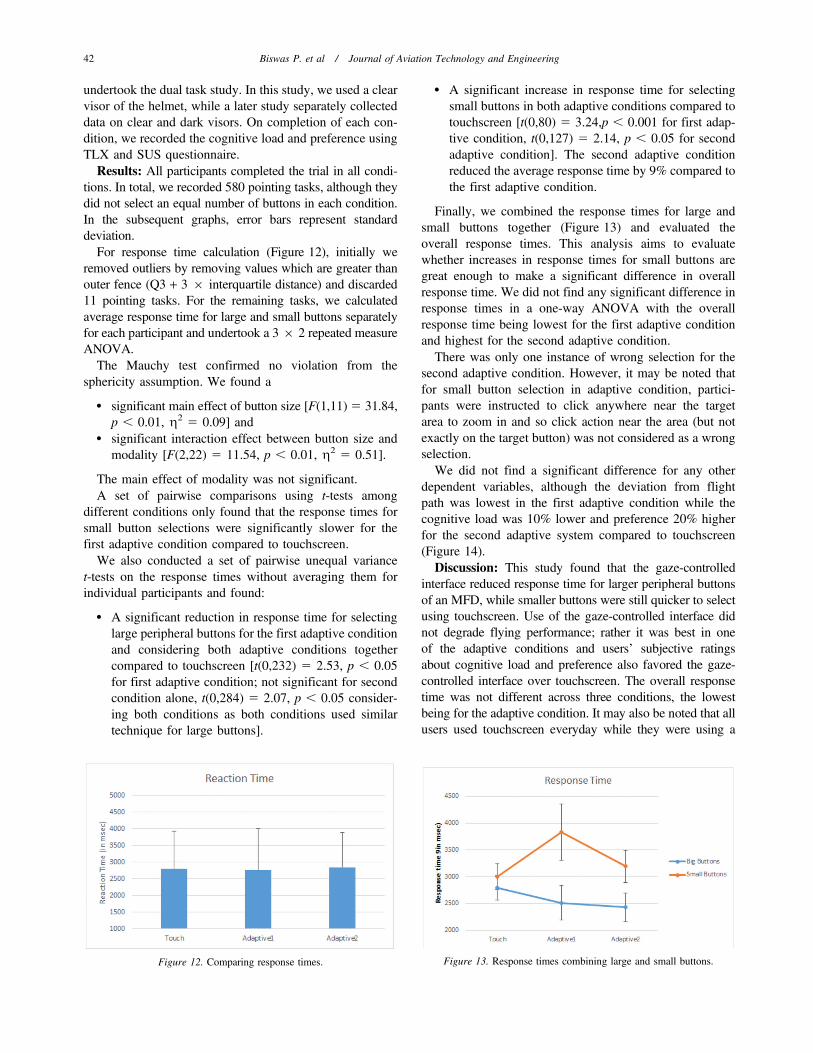
For response time calculation (Figure 12), initially weremoved outliers by removing values which are greater thanouter fence (Q3 + 3 6 interquartile distance) and discarded11 pointing tasks. For the remaining tasks, we calculatedaverage response time for large and small buttons separatelyfor each participant and undertook a 3 6 2 repeated measureANOVA.
The Mauchy test confirmed no violation from thesphericity assumption. We found a
N significant main effect of button size [F(1,11) 5 31.84,p , 0.01, g2 5 0.09] and
N significant interaction effect between button size andmodality [F(2,22) 5 11.54, p , 0.01, g2 5 0.51].
The main effect of modality was not significant.A set of pairwise comparisons using t-tests among
different conditions only found that the response times forsmall button selections were significantly slower for thefirst adaptive condition compared to touchscreen.
We also conducted a set of pairwise unequal variancet-tests on the response times without averaging them forindividual participants and found:
N A significant reduction in response time for selectinglarge peripheral buttons for the first adaptive conditionand considering both adaptive conditions togethercompared to touchscreen [t(0,232) 5 2.53, p , 0.05for first adaptive condition; not significant for secondcondition alone, t(0,284) 5 2.07, p , 0.05 consider-ing both conditions as both conditions used similartechnique for large buttons].
N A significant increase in response time for selectingsmall buttons in both adaptive conditions compared totouchscreen [t(0,80) 5 3.24,p , 0.001 for first adap-tive condition, t(0,127) 5 2.14, p , 0.05 for secondadaptive condition]. The second adaptive conditionreduced the average response time by 9% compared tothe first adaptive condition.
Finally, we combined the response times for large andsmall buttons together (Figure 13) and evaluated theoverall response times. This analysis aims to evaluatewhether increases in response times for small buttons aregreat enough to make a significant difference in overallresponse time. We did not find any significant difference inresponse times in a one-way ANOVA with the overallresponse time being lowest for the first adaptive conditionand highest for the second adaptive condition.
There was only one instance of wrong selection for thesecond adaptive condition. However, it may be noted thatfor small button selection in adaptive condition, partici-pants were instructed to click anywhere near the targetarea to zoom in and so click action near the area (but notexactly on the target button) was not considered as a wrongselection.
We did not find a significant difference for any otherdependent variables, although the deviation from flightpath was lowest in the first adaptive condition while thecognitive load was 10% lower and preference 20% higherfor the second adaptive system compared to touchscreen(Figure 14).
Discussion: This study found that the gaze-controlledinterface reduced response time for larger peripheral buttonsof an MFD, while smaller buttons were still quicker to selectusing touchscreen. Use of the gaze-controlled interface didnot degrade flying performance; rather it was best in oneof the adaptive conditions and users’ subjective ratingsabout cognitive load and preference also favored the gaze-controlled interface over touchscreen. The overall responsetime was not different across three conditions, the lowestbeing for the adaptive condition. It may also be noted that allusers used touchscreen everyday while they were using a
Figure 12. Comparing response times. Figure 13. Response times combining large and small buttons.
42 Biswas P. et al / Journal of Aviation Technology and Engineering
gaze-controlled interface for the first time. In a high-Genvironment, it is difficult to move one’s hand. Pilots willstill use saccadic eye gaze movement to watch MFDs andour gaze-controlled interface can leverage this gaze move-ment to directly control MFDs. Although users exhibitedsignificantly longer response time for small buttons inthe adaptive conditions, the one with dwell time selection(Adaptation 2) reduced pointing and selection time com-pared to the other adaptive condition (Adaptation 1) by 100ms on average. Future studies may adapt and optimize dwelltime duration to further reduce response times. In thefollowing studies, we explored the gaze-controlled interfaceas an HUD.
The following study rendered an MFD on a projecteddisplay configured as an HUD and evaluated its perfor-mance. We undertook a pointing and selection task similar tothis study and compared performance of the gaze-controlledinterface with respect to the standard TDS, presently used tooperate both HDDs and HMDs.
Study 2: HUD
This study involved similar tasks to the first study.However, instead of analyzing large and small buttonsseparately, we compared the gaze-controlled interface withdifferent visors of the helmet in a projected display.
Participants: We collected data from 11 participants(9 male, 2 female; age range 25 to 34 years) recruited fromour university with similar sampling criteria to the previousstudy discussed above. The participants had no visual,cognitive, and motor impairments and did not have anyproblem in using the experimental setup. None of them hadused either a HOTAS joystick or eye gaze tracking-basedinterface earlier.
Design and Material: The study used a similar set ofmaterials to the previous studies. We used the screenshot ofFigure 6 and each participant was instructed to make atleast eight selections for each condition while undertakingthe flying task. We also used a helmet given to us by HAL.The helmet had clear and dark visors. Since the eye gaze
tracker works based on reflected infrared light, we wantedto evaluate and compare the quality of interaction with adark visor. Our study consisted of the following threeconditions for pointing and selection tasks:
a. Using HOTAS joystick.b. Using eye gaze tracking with clear visor (ETC).c. Using eye gaze tracking with dark visor (ETD).
Procedure: We followed the same procedure as the firststudy but recorded data separately with clear and darkvisors.
Results: We initially analyzed the flight performanceunder three different conditions in terms of the standarddeviation in the x-axis, standard deviation in altitude whenthe flight was outside the envelope between 1000 and 2000feet, and total distance covered during the task. We did notfind any significant difference among those parametersin one-way ANOVAs. In fact, the deviation in altitude(Figure 15) was 10% less with eye gaze tracking with theclear visor compared to the HOTAS joystick.
Next we analyzed response times for 268 pointing tasksand found a significant difference among the three differentconditions [F(2,246) 5 9.65, p , 0.05, g2 5 0.07]. A setof pairwise t-tests also found significant difference betweenthe response times for the gaze-tracking system and theHOTAS joystick (Figure 16).
The number of wrong selections was measured andreported in terms of percent error, which was lowest forthe joystick and was under 10% for all conditions. Therewere four wrong selections for HOTAS, nine for eye gazetracking with the clear visor and six for eye gaze trackingwith the dark visor.
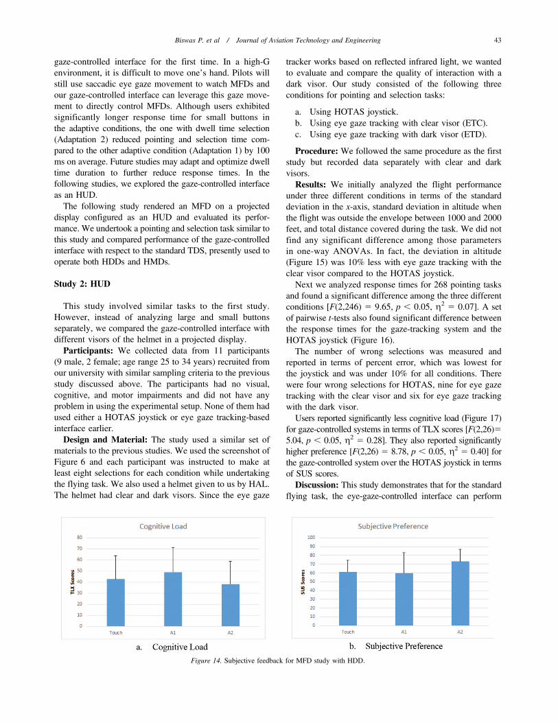
Users reported significantly less cognitive load (Figure 17)for gaze-controlled systems in terms of TLX scores [F(2,26)55.04, p , 0.05, g2 5 0.28]. They also reported significantlyhigher preference [F(2,26) 5 8.78, p , 0.05, g2 5 0.40] forthe gaze-controlled system over the HOTAS joystick in termsof SUS scores.
Discussion: This study demonstrates that for the standardflying task, the eye-gaze-controlled interface can perform
Figure 14. Subjective feedback for MFD study with HDD.
Biswas P. et al / Journal of Aviation Technology and Engineering 43

better than the existing HOTAS joystick in terms of bothresponse times and subjective preference. The averageresponse time was even lower than the gaze-controlledHDD reported by Biswas and Langdon (2015) in a single-task study. The flying performance in terms of deviationin altitude marginally improved for the gaze-controlledsystem compared to the joystick. User preference was alsosignificantly higher for the gaze-controlled system. Insummary, we can conclude that even for novice users, thegaze-controlled system can improve performance withsecondary mission control tasks in a military aviationenvironment without degrading the primary flying task.
Study 3: Simulated HMD
This study setup involved a screen at a sidewise positionof the pilot and used a wearable gaze tracker instead ofa screen-mounted one. We compared the gaze-controlledsystem with the TDS as in the previous study.
Participants: We collected data from nine participants(five male, four female; age range 25 to 34 years) recruitedfrom our university with similar sampling criteria to theprevious study discussed above. The participants had novisual, cognitive, and motor impairments and did not haveany problem in using the experimental setup. As they wererequired to wear eye-tracking glasses, we only selectedparticipants who did not have glasses or used contact lenses.
Material: We used Tobii Pro Glasses 2 (Tobii, 2018a)for tracking eye gaze and an HP Spectre laptop with Intel i7core processor to record and process gaze tracking datain real time. The flight simulator used a similar set ofmaterials to the previous studies described above.
Design: Participants were instructed to undertake 10pointing and selection tasks in parallel with the primaryflying task. We compared two conditions:
N Pointing and selection with TDS.N Pointing and selection with eye gaze tracking.
Figure 15. Quality of flying with respect to change in altitude.
Figure 16. Analyzing response times in flight simulator.
44 Biswas P. et al / Journal of Aviation Technology and Engineering

Procedure: We followed similar procedures to those ofthe previous two studies. The order of using TDS and gazetracker was randomized to avoid order effect.
Results: We did not find any significant difference in aWilcoxon signed rank test for primary flight parameters.However, standard deviations in the x-axis and in altitudewere both lower for the eye tracking system than for TDS(Figure 18).
We found a significant reduction in response times inthe eye tracking system compared to the joystick-basedTDS [W 5 245, p , 0.01]. All participants could selectthe target faster using the gaze-tracking system than usingTDS. Figure 19 shows the average response times forsecondary pointing and selection tasks. It may be notedthat all participants could undertake the secondary taskfaster using the gaze-controlled system than joystick-based TDS.
Finally, we compared the TLX and SUS scores as metricsof cognitive load and subjective preference (Figure 20). Thecognitive load measured through TLX was lower in theeye gaze tracking-based system, although the difference wasnot significant in a Wilcoxon sign rank test. The subjectivepreference measured through SUS score was significantlyhigher in the eye gaze tracking system in a Wilcoxon signrank test [W 5 31, p , 0.05].
Discussion: This study demonstrates that:
N One can use a wearable gaze tracker as a cursor con-trol device.
N One can use a wearable gaze tracker to control a GUIwhich is not in front of or in the line of sight of anoperator.
Existing HMDs used in fighter aircraft require anactuation by the HOTAS switch. Our study aims to eliminatethis HOTAS-based actuation by controlling the HMDthrough eye gaze. Although we did not use a real HMD,the same algorithm can be used as for a real HMD as therelative position of the eyes with respect to the display willnot change in an HMD and just one run of the calibrationroutine will be enough for the neural networks to converteye gaze coordinates to HMD coordinates. Existing HMDshave a 40˚ field of view (Collinson, 1996) while our setupworked within an 82˚ horizontal and 52˚ vertical field ofview. As the study shows, the gaze tracking system can sig-nificantly speed up a pointing and selection task compared tothe HOTAS joystick.
Study 4: Involving Military Pilots
The previous studies collected data from universitystudents. Senior pilots suggested collecting data fromuniversity students, as they thought that any new techno-logy is most likely to be tested first on a training plat-form with students with little flying knowledge ratherthan on an established platform with more experiencedpilots. We constantly took suggestions from experiencedpilots on designing the flight simulator and flying taskduring the design of the study. However, in the following
Figure 17. Subjective feedback for MFD study with HUD.
Figure 18. Quality of flying with respect to change in altitude and x-axis deviation.
Biswas P. et al / Journal of Aviation Technology and Engineering 45

subsections, we describe studies involving data collectedfrom military pilots.
We collected data from one pilot of wing commanderrank of the Indian Air Force for a gaze-controlled HDD.He could undertake 16 pointing tasks at an averageduration of 3.5 seconds (standard deviation 5 1.6 seconds)and reported a TLX score of 23 and SUS rating of 82. Theaverage time of selecting large buttons was 2.8 seconds,while that of small buttons was 4.3 seconds. The low TLXscore indicated less cognitive load and high SUS scoreindicated high subjective preference for the system.
In another study described below, we collected data insidean aircraft while flying. We aimed to compare performanceof the gaze-controlled system and the proposed nearestneighborhood algorithm that activates the nearest target onscreen from the present cursor location.
Participants: We collected data from three IAF pilots withranks ranging from squadron leader to wing commander.
Material: We collected data using a Microsoft SurfacePro tablet running Windows 10 operating system and aTobii PC EyeX Minni eye gaze tracker. We used an AvroHL768 transport aircraft for data collection and an X16-1DUSB accelerometer from Gulf Coast Data Concepts forrecording vibration in units of g (g 5 9.81 m/s2).
Design: We set up the tablet and eye gaze tracker at thefront seat outside the cockpit as shown in Figure 21.
We used the ISO 9241 pointing task with the followingtarget sizes and distances.
Target sizes (in cm): 1.9, 1.7, 1.5, 1.3, 1.1, 0.9.
Distance of target from center of screen (in cm): 5, 8.We designed a repeated measure study with the follow-
ing independent variables:
N Place of study
˚ On the ground
˚ In the air
N Type of system
˚ Non-adaptive
˚ Adaptive, with nearest neighborhood algorithm
We also used an accelerometer in front of the tabletcomputer to record vibration while flying.
Results: In total, we analyzed 956 pointing tasks with atleast 150 tasks recorded for each condition. We calculatedaverage movement time for all combinations of width anddistances to target for all different conditions. Figure 22plots the movement times with respect of indices of diffi-culties for all four conditions. We found correlation coeffi-cient r 5 0.64 and r 5 0.63 between movement time andID for the non-adapted versions on the ground and in the airrespectively. However, with the nearest neighborhoodalgorithm, the correlation coefficients were less than 0.3.
We undertook a place of study (2) 6 type of system(2) repeated measure ANOVA on the movement times. Wefound:
N A significant main effect of place of study F(1,10) 5
14.38, p , 0.05, g2 5 0.59.
Figure 19. Analyzing response times for simulated HMD.
Figure 20. Subjective feedback for simulated HMS study.
46 Biswas P. et al / Journal of Aviation Technology and Engineering

N A significant main effect of type of system F(1,10) 5
34.80, p , 0.05, g2 5 0.78.N An interaction effect of place of study and type of
system F(1,10) 5 7.78, p , 0.05, g2 5 0.44.
A set of pairwise comparisons found that there aresignificant differences at p , 0.05 in movement timesbetween data collected on the ground and in the air andbetween adapted and non-adapted conditions on data col-lected in the air.
In terms of qualitative feedback, all pilots preferred theadaptive version over the non-adaptive one. They notedthat the non-adaptive version is difficult to use duringtakeoff and landing phases compared to cruising phase. Interms of application, they noted that the system will beuseful for operating the MFD and operating the HMD forinvestigating and engaging beyond visual range targets.
We separately analyzed the vibration profile in terms ofthe acceleration values recorded for roll, pitch, and yaw.The roll and yaw vibration had a maximum value of 1.2G,while the acceleration measured for pitch reached 1.5G.
Discussion: The previous studies were conducted in alaboratory environment with a flight simulator. This studytook the system inside an aircraft and measured its per-formance in vibrating condition. This study shows that the
nearest neighborhood algorithm made selection of smallertargets easier, as indicated by the low value of correlationbetween movement time and ID. This ease of selection ofsmall targets is more useful in the air under vibratingcondition than on the ground as indicated by the ANOVAstudy and pairwise comparisons. It may also be noted thatusing the nearest neighborhood algorithm, participants canselect target using the gaze-controlled interface in less than2 seconds on average both on the ground and in the air.
However, in this study, we used two different devices formeasuring movement time and acceleration, and hencecannot synchronize on the milliseconds level. We could notmake separate analyses for different flying phases and,being in a transport aircraft, we could measure performanceof the gaze-controlled system up to 1.5G only. In our futurestudies, we are planning to collect data on a fighter aircraftattaining higher G values and also synchronizing the users’performance with vibration profiles.
Summary
Overall, we can conclude that the gaze-controlled systemcan improve performance with secondary tasks comparedto existing joystick-based TDS. The flying performance
Figure 21. Aircraft used in the study and placement of setup inside the aircraft.
Figure 22. Movement time versus ID plot.
Biswas P. et al / Journal of Aviation Technology and Engineering 47

was not affected by using the gaze-controlled interface;rather, it was slightly improved in terms of deviation fromflight envelope. In all three user studies, users’ subjectivefeedback also favored the gaze-controlled system overtouchscreen or TDS. In the following paragraphs weclarified a few issues about the design of our studies andimplementation of the adaptation techniques.
N Interference with caption for hotspots: When thebuttons have captions on them, it may be possible thatthe optimum position of the hotspot is on the captionitself. It may be noted that the aim of the hotspot is toleverage the pop-out effect and it need not to be aphysical spot itself. Bold-facing or rendering inreverse-contrast a single letter of the caption orplacing a high-contrast icon can also serve as ahotspot.
N Adaptable zooming technique: The zooming tech-nique was adaptable in the sense that the magnifica-tion ratio is selected based on the minimum distancebetween all pairs of targets at any point in time. Itwas implemented by drawing a window across therequired area, which in fact occluded part of thedisplay. However, the occlusion duration was limitedby the dwell time duration and was less than or equalto one second in the present implementation. Thezooming window disappeared as soon as a gaze loca-tion was recorded outside the zooming window. Wealso implemented a nearest neighborhood predictorwithin the zooming window so that users need not tobring the cursor exactly on target. Unlike existingwork, the magnification did not occur continuously,but rather initiated by pressing the slew button on thethrottle. Although we did not find a reduction inpointing times for small MFD buttons comparedto touchscreen, use of dwell time reduced reactiontimes by 9% compared with without it. The zoomingtechnique can also be used with other modalities, andfuture studies will explore further adaptation optionslike optimizing the dwell time (Nayyar et al., 2017).
N Simulated HMD: We could not use an actual HMDfor our study and instead had to use an LCD screenas a simulated HMD. Existing commercial gaze-controlled HMD (Ergoneers 2018; Tobii, 2018b)works as a virtual reality interface, but may reducesituational awareness of pilots. In our particular setup,if we used a virtual reality headset and configured itfor a secondary task, participants could not undertakethe primary flying task. Existing commercial (LumusTechnologies, 2018) and research work on see-throughdisplays mostly explored near-eye displays (Lewiset al., 2013; Plopski et al., 2015). However, existingHMDs in military aviation, like the Striker H II system(Striker, 2018), do not use near-eye display; rather,they project the display on a canopy. In our futurestudies, we plan to set up a pico-projector as an HMD;
however, our gaze-control algorithm will work for anydisplay after calibrating it for its relative position withrespect to the eyes. It may be noted here that therelative position of an HMD with respect to the eyeswill not be affected by head movement and only onecalibration will be sufficient for it to work as a gaze-controlled display.
N Selection for gaze control interface: In a gaze-controlled interface, selection of a target, popularizedas the Midas Touch problem, is not as straightforwardas with other interaction techniques such as touchsc-reen, touchpad, or mouse. A previous study by Biswasand Langdon (2015) explored hardware switchand voice command-based selection while researchon assistive technology (Penkar, Lutteroth, & Weber,2012) explored dwell time-based selection. Consi-dering the timing constraint, we used a button on thethrottle (slew button) for selecting a target in thereported user studies, while dwell time was used inone adaptive method and for the simulated HMD.
N Data analysis strategy: We checked normality bydrawing box plots and comparing mean and medianfor each individual dependent variable. If the datawere normally distributed, we conducted parametrictests; otherwise, we undertook nonparametric tests.For all graphs, the column represents average, whilethe error bar represents standard deviation.
Conclusion
This paper reports the results of three studies onundertaking pointing and selection tasks with a simulatedMFD using eye gaze in addition to flying an aircraft instraight and level maneuver, and compared performance ofboth flying and pointing tasks with state-of-the-art interac-tion devices (touchscreen and TDS). We also exploredpossibilities of rendering an MFD as a HUD instead oftraditional HDD configuration. For conducting the study,we designed bespoke hardware as a working prototypeof a configurable HUD and designed and implementednew algorithms to control an on-screen cursor throughan operator’s eye gaze. Using our setup that consists ofhelmet, gloves, and HOTAS used in existing militaryaircraft, participants could undertake pointing and selectiontasks in an average time of 2.43 seconds (Figure 11) forHDD and 1.9 seconds (Figure 18) for HUD. This timeestimation includes context switching from primary flyingto secondary pointing task and was significantly better thanexisting TDS (2.67 seconds) and touchscreen (2.8 seconds).We configured a wearable gaze tracker as a cursor con-trol device using a neural network-based algorithm. Usingthat, participants could undertake pointing and selectiontasks statistically significantly faster than TDS in a side-wise display configured as a simulated HMD. We envi-sion alleviating the need of HOTAS-based actuation for
48 Biswas P. et al / Journal of Aviation Technology and Engineering

operating an HMD by using an eye-tracking glass. Wetested the system inside an aircraft: military pilots couldundertake representative pointing and selection tasks usingthe gaze-controlled interface in less than 2 seconds, onaverage. The proposed algorithms for the gaze-controlledinterface can also be extended to other areas like auto-motive control and assistive technology.
Acknowledgements
This work was funded by a grant from the AeronauticalResearch and Development Board, India.
References
BAE Systems. (2018). BAES 6th generation cockpit. Retrieved fromhttps://www.aerosociety.com/news/wearable-cockpits-the-ultimate-human-machine-interface
Bates, R. (1999). Multimodal eye-based interaction for zoomed target selec-tion on a standard graphical user interface. Proceedings of INTERACT1999.
Biswas, P., & Langdon, P. (2014). Eye-gaze tracking based interaction inIndia. Procedia Computer Science, 39, 59–66.
Biswas, P., & Langdon, P. (2015). Multimodal intelligent eye-gazetracking system. International Journal of Human-Computer Interaction,31(4), 277–294.
Biswas, P., Prabhakar, G., Rajesh, J., Pandit, K., & Halder, A. (2017).Improving eye gaze controlled car dashboard using simulated annea-ling. Proceedings of the 31st British Human Computer InteractionConference (HCI 17).
Collinson, R. P. G. (1996). Introduction to avionics systems. Dordrecht,The Netherlands: Springer.
de Reus, A. J. C., Zon, R., & Ouwerkerk, R. (2012). Exploring the use ofan eye tracker in a helmet mounted display. Avionics EuropeConference & Exhibition, Munich, Germany, March 21–22, 2012.
Dixon, M., Fogarty, J., & Wobbrock, J. (2012). A general-purpose target-aware pointing enhancement using pixel-level analysis of graphicalinterfaces. Proceedings of the 2012 ACM Annual Conference on HumanFactors in Computing Systems (pp. 3167–3176). New York, NY: ACM.
Ergoneers. (2018). Eye tracking head mounted displays. Retrieved fromhttps://www.ergoneers.com/en/en/hardware/eye-tracking/head-mounted
Eurofighter. (2017). Flight manual for the package Eurofighter TyphoonProfessional. Retrieved from https://www.afs-design.de/pdf/AFS_EFpro_English.pdf
Farrell, S., & Zhai, S. (2005). System and method for selectively expan-ding or contracting a portion of a display using eye-gaze tracking. USPatent 20050047629 A1.
Furness, T. A. (1986, September/October). The super cockpit and itshuman factors challenges. Proceedings of the Human Factors andErgonomics Society Annual Meeting (Vol. 30, pp. 48–52). Dayton,Ohio, USA.
Grandt, M., Pfendler, C., & Mooshage, O. (2013). Empirical comparisonof five input devices for anti-air warfare operators. Retrieved fromhttp://dodccrp.org/events/8th_ICCRTS/pdf/035.pdf
Handa, S., & Ebisawa, Y. (2008). Development of head-mounted displaywith eye-gaze detection function for the severely disabled. Proceedingsof the IEEE International Conference on Virtual Environments, Human-Computer Interfaces, and Measurement Systems, Istanbul, Turkey.
Hierl, R., Neujahr, H., & Sandl, P. (2012). Military aviation. In M. Stein &P. Sandl (Eds.), Information ergonomics: A theoretical approach and
practical experience in transportation (pp. 159–195). Berlin, Germany:Springer Science & Business Media.
HOTAS (2017). Retrieved from http://www.thrustmaster.com/products/hotas-warthog
Huey, E. (1908). The psychology and pedagogy of reading (Reprint). MITPress 1968.
Jacob, M., Hurwitz B., & Kamhi, G. (2013). Eye tracking based selectiveaccentuation of portions of a display. WO Patent 2013169237 A1.
Lewis, J. R., Wei, Y., Crocco, R. L., Vaught, B. I., Kipman, A. A. A., &Perez, K. S. (2013). Gaze detection in a see-through, near-eye, mixedreality display. US Patent Application US 2013/0050070 A1.
Lumus Technologies. (2018). Retrieved from https://lumusvision.com/McGuffin, M. J., & Balakrishnan, R. (2005). Fitts’ law and expanding
targets: Experimental studies and designs for user interfaces. ACMTransactions on Computer-Human Interaction, 4(12), 388–422.
Murata, A. (1998). Improvement of pointing time by predicting targets inpointing with a PC mouse. International Journal of Human-ComputerInteraction, 10(1), 23–32.
Nayyar, A., Dwivedi, U., Ahuja, K., Rajput, N., Nagar, S., & Dey, K.(2017). OptiDwell: Intelligent adjustment of dwell click time. Pro-ceedings of 22nd International Conference on Intelligent UserInterfaces (pp. 193–204). New York, NY: ACM.
Pasqual, P., & Wobbrock, J. (2014). Mouse pointing endpoint predic-tion using kinematic template matching. Proceedings of the SIGCHIConference on Human Factors in Computing Systems (pp. 743–752).New York, NY: ACM.
Penkar, A. M., Lutteroth, C., & Weber, G. (2012). Designing for the eye:Design parameters for dwell in gaze interaction. Proceedings of the24th Australian Computer-Human Interaction Conference (pp. 479–488). New York, NY: ACM.
Pfeuffer, K., & Gellersen, H. (2016). Gaze and touch interaction on tablets.Proceedings of the 29th Annual Symposium on User Interface Softwareand Technology (pp. 301–311). New York, NY: ACM.
Plopski, A., Itoh, Y., Nitschke, C., Kiyokawa, K., Klinker, G., & Takemura,H. (2015). Corneal-imaging calibration for optical see-through head-mounted displays. IEEE Transactions on Visualization and ComputerGraphics, 21(4), 481–490.
Poitschke, T., Laquai, F., Stamboliev, S., & Rigoll, G. (2011). Gaze-basedinteraction on multiple displays in an automotive environment. IEEEInternational Conference on Systems, Man, and Cybernetics (pp. 543–548). Piscataway, NJ: IEEE.
Ruiz, J., & Lank, E. (2010). Speeding pointing in tiled widgets: Under-standing the effects of target expansion and misprediction. Proceedingsof the 15th International Conference on Intelligent User Interfaces(pp. 229–238). New York, NY: ACM.
Salomon, D. (2005). Curves and surfaces for computer graphics. Berlin,Germany: Springer Verlag.
Striker. (2018). StrikerH II Helmet. Retrieved from https://www.baesystems.com/en/product/striker-ii-digital-helmet-mounted-display
SUS. (2014). System Usability Scale. Retrieved from http://en.wikipedia.org/wiki/System_usability_scale
Thomas P. (2018). Performance, characteristics, and error rates of cursorcontrol devices for aircraft cockpit interaction. International Journal ofHuman-Computer Studies, 109, 41–53.
Thomas, P., Biswas, P., & Langdon, P. (2015). State-of-the-art and futureconcepts for interaction in aircraft cockpits. In, M. Antona & C.Stephanidis (Eds.), Universal access in human-computer interaction.Access to interaction (pp. 538–549). Cham, Switzerland: Springer.
Tobii. (2018a). Tobii Pro Glasses 2. Retrieved from https://www.tobiipro.com/product-listing/tobii-pro-glasses-2/
Tobii. (2018b). Tobii Tech Virtual Reality. Retrieved from https://www.tobii.com/tech/products/vr/
TopGunMilitary. (2013, May). Army AH064 attack helicopter [Video file].Retrieved from https://www.youtube.com/watch?v=UruW0N2mPsY
Biswas P. et al / Journal of Aviation Technology and Engineering 49

Vertegaal, R. (2008). A Fitts law comparison of eye tracking and manualinput in the selection of visual targets. Proceedings of the 10thInternational Conference on Multimodal Interfaces (pp. 241–248).New York, NY: ACM. https://doi.org/10.1145/1452392.1452443
Ware, C., & Mikaelian, H. M. (1987). An evaluation of an eye tracker asa device for computer input. Proceedings of the SIGCHI Conferenceon Human Factors in Computing Systems (pp. 183–187). New York,NY: ACM.
Wood, R. B., & Howells, P. J. (2001). Head-up displays: The avionicshandbook. Boca Raton, FL: CRC Press.
Zhai, S., Morimoto, C., & Ihde, S. (1999). Manual and gaze inputcascaded (MAGIC) pointing. Proceedings of the SIGCHI Conferenceon Human Factors in Computing Systems (pp. 246–253). New York,NY: ACM.
L. R. D. Murthy, received a B.Tech degree in electrical and electronicsengineering from SASTRA University, India in 2015. He is currentlypursuing a PhD at the Intelligent Inclusive Interaction Design (I3D) lab inthe Centre for Product Design and Manufacturing, Indian Institute ofScience. His research interests include multimodal human computerinteraction, machine learning, and artificial intelligence.
Jeevithashree DV, is a doctoral student from Intelligent InclusiveInteraction Design (I3D) Lab, Centre for Product Design andManufacturing (CPDM), Indian Institute of Science (IISc), Bangalore.She holds a master’s degree in Computer Science & Engineering from VITUniversity, Vellore and a bachelor’s in information science andengineering from PESIT Bangalore. She is currently working oninvestigating Human Computer Interaction issues in a limited mobilityenvironment for developing intelligent eye gaze-controlled interfaces. Herresearch mainly focuses on two distinct user groups: children with severespeech and motor impairment (SSMI) and military fast jet pilots.
Pradipta Biswas, is an assistant professor at the Centre for Product Designand Manufacturing of Indian Institute of Science and co-chair of StudyGroup 9 at the International Telecommunication Union. His researchfocuses on user modelling and multimodal human-machine interaction foraviation and automotive environments and for assistive technology.Earlier, he was a senior research associate in the Engineering Department,a research fellow at Wolfson College, and a research associate at TrinityHall of the University of Cambridge. He completed a PhD in computerscience at the Rainbow Group of the University of Cambridge ComputerLaboratory and Trinity College in 2010, and was awarded a Gates-Cambridge Scholarship in 2006.
Kamal Preet Singh Saluja, is a researcher at the Intelligent InclusiveInteraction Design (I3D) lab, Centre for Product Design andManufacturing (CPDM), Indian Institute of Science (IISc), Bangalore.He earned his first degree in computer science and engineering from RajivGandhi Proudyogiki Vishwavidyalaya, Bhopal. He is investigating designconstraints and developing eye gaze-controlled interaction systems forchildren with severe speech and motor impairment. He is also working onassessing cognitive impairment in elderly people.
50 Biswas P. et al / Journal of Aviation Technology and Engineering