operating and service instructions · 2020-01-08 · smart uv lite models smart uv specifications...
TRANSCRIPT
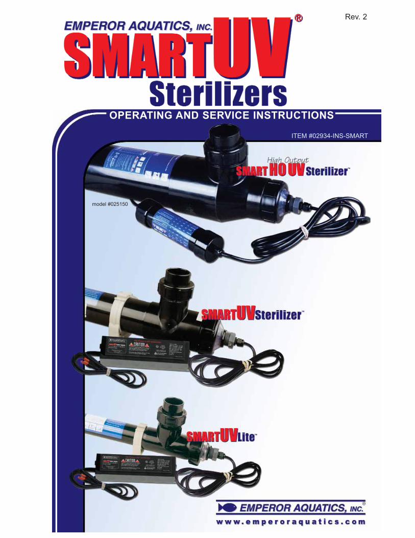
OPERATING AND SERVICE INSTRUCTIONS
ITEM #02934-INS-SMART
model #025150
Rev. 2

OPERATING AND SERVICE INSTRUCTIONS
Congratulations on the purchase of your new SMART UV, we
want you to be safe and successful with our equipment so please,
read our instructions prior to installing and operating this equipment!
Section One: SAFETY RULES FOR ALL SMART UV MODELS - pg. 1- 2
Section Two: UV STERILIZATION FEATURES AND SPECIFICATIONS - pg. 2 - 5
Section Three: WHAT IS ULTRAVIOLET STERILIZATION - pg. 6
Section Four: PRE-INSTALLATION INSPECTION - pg. 6 - 8
Section Five: QUARTZ SLEEVE/UV LAMP INSPECTION - pg. 9 - 11
Section Six: THE QUARTZ SLEEVE ASSEMBLY - pg. 11 - 13
Section Seven: MOUNTING YOUR SMART UV - pg. 13 - 14
Section Eight: MANDATORY SMART UV WATER TESTING - pg. 14 - 15
Section Nine: ELECTRICAL REQUIREMENTS - pg. 15 - 16
Section Ten: UV LAMP INSTALLATION- pg. 16 - 17
Section Eleven: QUARTZ SLEEVE WIPERS - pg. 17 - 19
Section Twelve: SMART UV INSTALLATION/OPERATION - pg. 20 - 25
Section Thirteen: SMART UV WINTERIZING - pg. 26
Section Fourteen: SMART UV MAINTENANCE - pg. 26 - 27
Section Fifteen: SMART UV REPLACEMENT PARTS - pg. 28 - 31
Section Sixteen: TROUBLESHOOTING - pg. 32
Section Seventeen: CONTACT INFO - pg. 32
Warranty - pg. 33
Other Emperor Aquatics, Inc. Products - pg. 34 - 35
For pond calculating measurements and essential water quality parameters please
visit us at: www.emperoraquatics.com
Section One: SAFETY RULES FOR ALL SMART UV MODELS
1
DANGER: To avoid possible electric shock, special care should be taken since
water is employed in the use of this aquarium and pond equipment. For each of
the following situations, do not attempt repairs yourself. Call EMPEROR
AQUATICS, Inc. customer service department at 610-970-0440 Ext. 0 for
services or discard the appliance.
DANGER: If the unit falls into the water, DO NOT REACH FOR IT! First unplug
it and then retrieve it. If the internal electrical components of the unit get wet,
unplug the unit immediately.
IMPORTANT SAFETY INSTRUCTIONS PLEASE READ PRIOR TO
INSTALLATION AND OPERATION
WARNING TO GUARD AGAINST INJURY, BASIC SAFETY PRECAUTIONS
SHOULD BE OBSERVED, INCLUDING THE FOLLOWING:
Water and electricity can be a dangerous combination.
Help us ensure your safety
PLEASE READ AND FOLLOW ALL SAFETY INSTRUCTIONS.
DANGER: If the unit shows any sign of water leakage, immediately unplug it from
the power source.
IMPORTANT: Carefully examine the unit after installation. It should not be
plugged in if there is water on any part not intended to be wet.
DANGER: Do not operate this unit if it has a damaged cord or plug, if it is mal-
functioning, or if it has been dropped or damaged in any manner.
DANGER: WARNING-Ultraviolet light is damaging to your eyes and skin!
Do not handle or stare at an operating UV lamp. Note that the UV light rays are
invisible to the human eye and precautions should be taken to prevent UV energy
from entering the eyes.
IMPORTANT: READ AND OBSERVE ALL IMPORTANT NOTICES AND LABELS
ON THE UNIT.
IMPORTANT: For Your Safety - The quartz sleeve and or the UV lamp in this
product may have been broken or damaged during transit! It is therefore
ESSENTIAL that the unit be CAREFULLY INSPECTED BEFORE CONNECTING
TO ELECTRIC POWER (See Section Five)
WARNING: Do NOT exceed 20 PSI (Pounds Per Square Inch)
IMPORTANT: Close supervision is necessary when any appliance is used by or
near children, and our equipment is no exception.
IMPORTANT: Always unplug the unit from an electrical outlet when not in use,
before servicing, cleaning or removing parts. Never yank the cord to pull the plug
from the outlet. Grasp the plug and pull to disconnect.
IMPORTANT: SMART UVs are designed for low-pressure water applications with
or without aquatic livestock. DO NOT use the EMPEROR AQUATICS, Inc.
SMART UV for any application other than its intended use. The use of
attachments not recommended or sold by Emperor Aquatics Inc. may
cause unsafe conditions and possibly void any warranty.
IMPORTANT: This unit must be wired in conjunction with a properly
grounded, ground fault interrupter circuit (GFI). Only (3) three wire grounded
cables suitable for outdoor use should be used to connect this unit. If joining
cables for outdoor use, a suitable watertight cable connector must be used. If an
extension cord is necessary, a cord with a proper rating should be used. A cord
rated for less amperes or watts than the appliance’s rating may overheat. Care
should be taken to arrange the cord so that it will not be tripped over or pulled. (If
in doubt consult a qualified electrician)
NOTE: Warping of the UV body may occur when left in direct sun light without
water inside to help dissipate the heat.
WARNING: DO NOT operate the unit in “no-flow” situations.
Section Two: UV STERILIZATION FEATURES AND SPECIFICATIONS
2
Our GPH T-5 and T-6 low pressure mercury vapor germicidal lamps, convert
approximately 40% of their electrical input watts into UV-C output watts within the
germicidal action spectrum (meaning 40% of electricity used is converted into
useful germicidal UV light), the highest UV-C output conversion among all UV
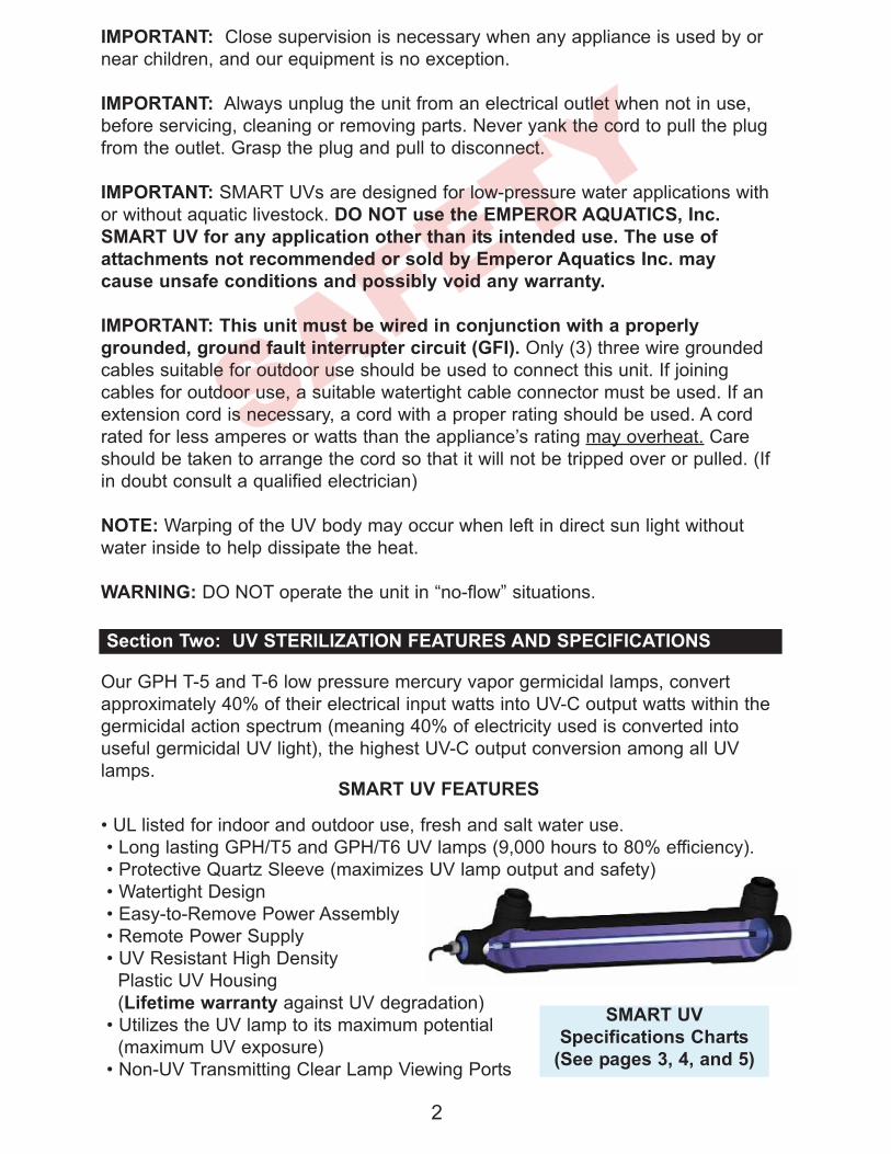
lamps.SMART UV FEATURES
• UL listed for indoor and outdoor use, fresh and salt water use.
• Long lasting GPH/T5 and GPH/T6 UV lamps (9,000 hours to 80% efficiency).
• Protective Quartz Sleeve (maximizes UV lamp output and safety)
• Watertight Design
• Easy-to-Remove Power Assembly
• Remote Power Supply
• UV Resistant High Density
Plastic UV Housing
(Lifetime warranty against UV degradation)
• Utilizes the UV lamp to its maximum potential
(maximum UV exposure)
• Non-UV Transmitting Clear Lamp Viewing Ports
SMART UV
Specifications Charts
(See pages 3, 4, and 5)

SM
AR
T U
V L
ite
Mo
de
ls
SM
AR
T U
V S
pe
cif
ica
tio
ns
Ch
art
s
3
No
te:
PV
C A
da
pte
r K
its n
ot
inclu
de
d (
bu
t a
va
ilab
le s
epa
rate
ly)
"S
ug
ge
ste
d" W
ate
r F
low
Ra
tes
are
ba
se
d o
n U
V L
am
p E
nd
of
Use
ful L
am
p L
ife
, 9
,00
0 h
rs.
@ 8
0%
ou
tpu
t. M
ax
imu
m W
ate
r F
low
Ra
tes
are
ba
se
d o
n N
ew
La
mp
Co
nd
itio
n. A
ll w
ate
r flo
w r
ate
s in
co
rpo
rate
a 9
0%
UV
tra
nsm
itta
nce
fa
cto
r, c
on
sid
erin
g "
Gre
en
Wa
ter"
co
nd
itio
ns.
WA
RN
ING
:D
o N
OT
exce
ed
20
PS
I (P
ou
nd
s P
er
Sq
ua
re I
nch
)

SM
AR
T U
V S
teri
lize
r M
od
els
4
WA
RN
ING
:D
o N
OT
exce
ed
20
PS
I (P
ou
nd
s P
er
Sq
ua
re I
nch
)
No
te:
PV
C A
da
pte
r K
its n
ot
inclu
de
d (
bu
t a
va
ilab
le s
epa
rate
ly)
"S
ug
ge
ste
d" W
ate
r F
low
Ra
tes
are
ba
se
d o
n U
V L
am
p E
nd
of
Use
ful L
am
p L
ife
, 9
,00
0 h
rs.
@ 8
0%
ou
tpu
t. M
ax
imu
m W
ate
r F
low
Ra
tes
are
ba
se
d o
n N
ew
La
mp
Co
nd
itio
n. A
ll w
ate
r flo
w r
ate
s in
co
rpo
rate
a 9
0%
UV
tra
nsm
itta
nce
fa
cto
r, c
on
sid
erin
g "
Gre
en
Wa
ter"
co
nd
itio
ns.

SM
AR
T H
igh
-Ou
tpu
t U
V S
teri
lize
r M
od
els
5
WA
RN
ING
:D
o N
OT
exce
ed
20
PS
I (P
ou
nd
s P
er
Sq
ua
re I
nch
)
No
te:
PV
C A
da
pte
r K
its n
ot
inclu
de
d (
bu
t a
va
ilab
le s
epa
rate
ly)
"S
ug
ge
ste
d" W
ate
r F
low
Ra
tes
are
ba
se
d o
n U
V L
am
p E
nd
of
Use
ful L
am
p L
ife
, 9
,00
0 h
rs.
@ 8
0%
ou
tpu
t. M
ax
imu
m W
ate
r F
low
Ra
tes
are
ba
se
d o
n N
ew
La
mp
Co
nd
itio
n. A
ll w
ate
r flo
w r
ate
s in
co
rpo
rate
a 9
0%
UV
tra
nsm
itta
nce
fa
cto
r, c
on
sid
erin
g "
Gre
en
Wa
ter"
co
nd
itio
ns.
6
Section Three: WHAT IS ULTRAVIOLET STERILIZATION
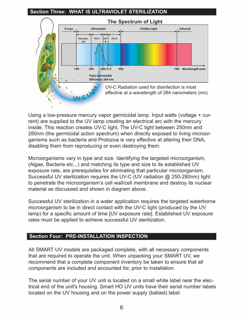
Using a low-pressure mercury vapor germicidal lamp. Input watts (voltage + cur-
rent) are supplied to the UV lamp creating an electrical arc with the mercury
inside. This reaction creates UV-C light. The UV-C light between 250nm and
280nm (the germicidal action spectrum) when directly exposed to living microor-
ganisms such as bacteria and Protozoa is very effective at altering their DNA,
disabling them from reproducing or even destroying them.
Microorganisms vary in type and size. Identifying the targeted microorganism,
(Algae, Bacteria etc...) and matching its type and size to its established UV
exposure rate, are prerequisites for eliminating that particular microorganism.
Successful UV sterilization requires the UV-C (UV radiation @ 250-280nm) light
to penetrate the microorganism’s cell wall/cell membrane and destroy its nuclear
material as discussed and shown in diagram above.
Successful UV sterilization in a water application requires the targeted waterborne
microorganism to be in direct contact with the UV-C light (produced by the UV
lamp) for a specific amount of time [UV exposure rate]. Established UV exposure
rates must be applied to achieve successful UV sterilization.
UV-C Radiation used for disinfection is most
effective at a wavelength of 264 nanometers (nm).
The Spectrum of Light
Section Four: PRE-INSTALLATION INSPECTION
All SMART UV models are packaged complete, with all necessary components
that are required to operate the unit. When unpacking your SMART UV, we
recommend that a complete component inventory be taken to ensure that all
components are included and accounted for, prior to installation.
The serial number of your UV unit is located on a small white label near the elec-
trical end of the unit's housing. Smart HO UV units have their serial number labels
located on the UV housing and on the power supply (ballast) label.
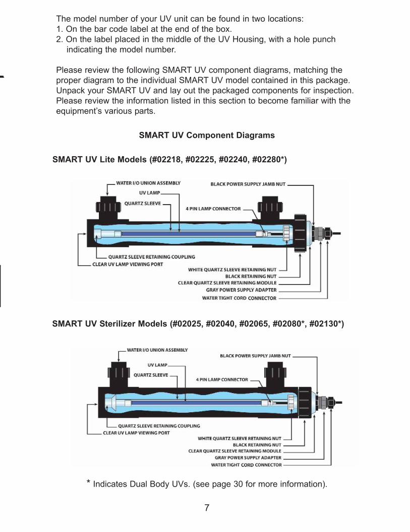
SMART UV Component Diagrams
SMART UV Lite Models (#02218, #02225, #02240, #02280*)
SMART UV Sterilizer Models (#02025, #02040, #02065, #02080*, #02130*)
7
The model number of your UV unit can be found in two locations:
1. On the bar code label at the end of the box.
2. On the label placed in the middle of the UV Housing, with a hole punch
indicating the model number.
Please review the following SMART UV component diagrams, matching the
proper diagram to the individual SMART UV model contained in this package.
Unpack your SMART UV and lay out the packaged components for inspection.
Please review the information listed in this section to become familiar with the
equipment’s various parts.
* Indicates Dual Body UVs. (see page 30 for more information).

SMART HO UV Sterilizer Models (#025050, #025080, #025120, #025150)
8
Included: UV Housing, Power Supply w/cord, Quartz Sleeve Assembly,
Lamp, Packet Containing Instructions, and Inlet/Outlet fittings
(fittings vary per unit)
- After Inventory is taken...make sure nothing is missing or damaged -
Power Supplies
Part Number20100 - 18 - W, 25 - W, 40 - W, 65 - W
80 - W (x2), 130 - W (x2)
Fits SMART UV Lites and SMART UV
Models 18 through 130 Watt
Part Numbers202150-1 - 150 W
Fits SMART HO UV
Model 150 Watt
Fits SMART HO UV Models 37 through
120 Watt
Part Number20105-MV - 37 - W, 50 - W, 80 - W, 120 - W

9
(1) The following SMART UV Models are packaged with their
quartz sleeve assembly pre-assembled inside the UV
housing, the lamp is packaged separately in a corrugated
tube.
SMART Lite #02218, #02218-W, #02225, #02225-W, #02240, #02240-W,
#02280, #02280-W
SMART UV #02025, #02025-W, #02040, #02040-W, #02080, #02080-W,
SMART HO UV #025050, #025050-W, #025080, #025080-W
The Quartz Sleeve Assembly must be removed from the UV housing and
inspected for damage prior to installation. Extreme care should be used
while this procedure is being performed.
Step # 2 - Carefully, remove the quartz sleeve by unthreading the Black
Retaining Nut. Gently slide out the quartz sleeve assembly and inspect for
damage including chips, cracks and pin holes. If damage has occurred please
contact the place of original purchase immediately.
Quartz Sleeve/UV lamp Inspection Procedure
Step # 1- Carefully unpack the UV lamp(s) from
their corrugated packing tubes and inspect for
damage including broken glass, cracks, chips,
fractures and pin holes. If damage has
occurred please contact the place of
original purchase immediately.
Step # 3 - After inspection, reassemble the quartz sleeve back into the UV
housing. If installing the unit perform the Mandatory Water Test (See page 14).
Section Five: QUARTZ SLEEVE/UV LAMP INSPECTION
on
sed on
(used
models
Wiper
er
iper
s)
or
10
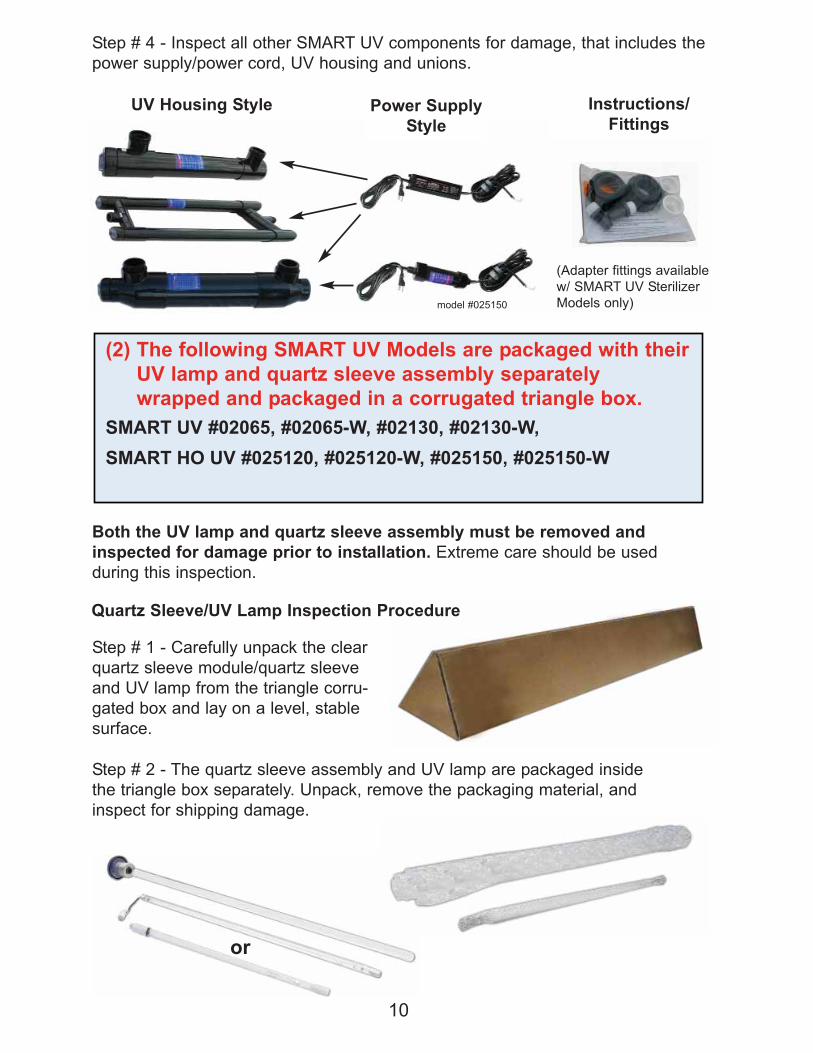
Step # 4 - Inspect all other SMART UV components for damage, that includes the
power supply/power cord, UV housing and unions.
(2) The following SMART UV Models are packaged with their
UV lamp and quartz sleeve assembly separately
wrapped and packaged in a corrugated triangle box.
SMART UV #02065, #02065-W, #02130, #02130-W,
SMART HO UV #025120, #025120-W, #025150, #025150-W
Both the UV lamp and quartz sleeve assembly must be removed and
inspected for damage prior to installation. Extreme care should be used
during this inspection.
Step # 1 - Carefully unpack the clear
quartz sleeve module/quartz sleeve
and UV lamp from the triangle corru-
gated box and lay on a level, stable
surface.
Quartz Sleeve/UV Lamp Inspection Procedure
Step # 2 - The quartz sleeve assembly and UV lamp are packaged inside
the triangle box separately. Unpack, remove the packaging material, and
inspect for shipping damage.
UV Housing Style Power Supply
Style
Instructions/
Fittings
(Adapter fittings available
w/ SMART UV Sterilizer
Models only)model #025150

11
Step # 3 - Inspect all other SMART UV components for damage, namely the
power supply, UV housing and unions, prior to installation.
After receipt and inspection of the unit, if broken glass is found including
cracks, chips, pin holes and hair line fractures of any kind) please contact
the place of original purchase immediately for replacements. Do NOT call
the manufacturer (Emperor Aquatics, Inc.) regarding this problem.
Section Six: THE QUARTZ SLEEVE ASSEMBLY
All SMART UVs utilize the same style quartz sleeve module assembly.
(with the only exception being item #5 “clear quartz sleeve module”)
There are 7 components that make up a complete assembly and they include:
1. Quartz Sleeve
2. White Quartz Sleeve Retaining Nut
3. Rubber Gasket
4. Rubber O-ring
5. Clear Quartz Sleeve Module (#20622- UV Lite Models /
#20603 UV Sterilizer & HO
UV Sterilizer Models)
6. Clear Quartz Sleeve Module O-ring
7. Power Supply Gasket
Improper Assembly May Result In Electrical Component Water
Damage and Unsafe ConditionsEmperor Aquatics, Inc. is not responsible for improper re-assembly of these parts.
UV Housing Style Power Supply
Style
Instructions/
Fittings
(Adapter fittings available
w/ SMART UV Sterilizer
Models only)
model #025150

12
6-1 First, position the white quartz sleeve retaining nut,
rubber gasket and rubber o-ring over the open-end of
the quartz sleeve as shown in Photo A.
6-2 Slide the "open-end" of the quartz sleeve (with
nut/gasket & o-ring in position) into the clear quartz
sleeve module (See Photo A).
Assembly Instructions
6-3 Thread the white retaining nut onto the clear quartz
sleeve module's male threads and hand-tighten
(See Photo B).
A
6-4 While hand-tightening the white retaining nut onto
the clear quartz sleeve module probe with your index
finger inside the clear Q.S. module. Make sure that the
open-end of the quartz sleeve mates smoothly with the
inside lip of the clear Q.S. module; this signifies a good
fit (See Photo C).
6-5 With the quartz sleeve is positioned inside the clear
quartz sleeve module properly, finish hand-tightening the
white retaining nut. With the white retaining nut "tight",
the quartz sleeve should appear "straight" inside the
clear quartz sleeve module (See Photo D), if it appears
crooked, it may leak, in which case disassemble and try
again.
6-6 Slide the quartz sleeve assembly into the UV hous-
ing carefully (See Photo E). The domed-end of the
quartz sleeve should slide into the coupling located on
the non-electrical end of the UV housing. (See Photo G
on pg.13)
6-7 With the quartz sleeve assembly properly in place,
the clear quartz sleeve retaining module should sit flush
against the top of the UV housing (see photo F).
B
C
D
E
F
Note: Make sure that the “clear quartz sleeve module
O-ring is in place”, item #6.

13
6-9. Please wait to install/connect the UV lamp and power supply until
section Ten.
6-8 Thread the black retaining nut (See Photo H) onto the male threads of
the UV housing, hand-tighten only.
Section Seven: MOUNTING YOUR SMART UV
NOTE: The way UVs are mounted/positioned plays a very important role in the
unit's performance and degree of safety. We STRONGLY RECOMMEND that
you follow these instructions and guidelines precisely. Any deviation from these
mounting instructions will void any warranty associated with the UV and all its
components and may cause unsafe conditions.
Trapped air inside the UV housing during operation may create excessive
heat, thus damaging the UV’s internal components. (Follow instructions to avoid this.)
Vertical Mounting: Mount the SMART UV with
the electrical end up. Use the bottom port as
the inlet with the top port as the outlet.
Horizontal Mounting: Mount the SMART UV
horizontally with the inlet/outlets facing up. If
the unit is mounted horizontally but not level,
the electrical end of the unit should be posi-
tioned higher than the non-electrical end.
Choose the lower port for the inlet.
Power Supply Mounting: DO NOT SUBMERGE THE POWER SUPPLY IN
WATER. The power supply may be camouflaged using rocks.
Note: Do not bury or place the power supply where heat or moisture can be
retained.
Note: The UV Sterilizer may be covered in a thin layer of mulch but do not bury
the unit.
Quartz Sleeve Coupling Black Retaining Nut
G H

14
DO NOT mount/use
the dual body UV
(80 & 130 watt
models) with one
"tube" on top of
the other or with
one "tube" higher
than the other.
Keep unit as flat
and level as
possible. Horizontal Mounting
(Overhead View on ground)Vertical Mounting
(Side View on wall)
Section Eight: MANDATORY SMART UV WATER TESTING
A water test should be performed each time the quartz sleeve(s) is installed inside
the unit's housing or when the quartz sleeve or gaskets and o-rings are replaced.
[Once annually] Performing a water test is a precautionary measure that will
determine whether or not the critical seal between the quartz sleeve and quartz
sleeve module has been achieved.
Failure to achieve a proper quartz sleeve/quartz sleeve module seal during
SMART UV operation will allow water to leak into the inside of the quartz sleeve,
potentially damaging the UV lamp and other electrical components, which could
develop into dangerous situations.
Five Steps to Water Test All SMART UV
Models8-1. Prepare the SMART UV for permanent
operation by plumbing it in-line, into a filter
system using the plumbing hardware of your
choice. If PVC glue is used, follow the glue
manufacturer’s instructions. Use a bypass
assembly for greater water flow control.
(as shown to the right)
Important Note: Failure to perform a water test could lead to conditions that will
void your product's warranties.
For instructions regarding the re-installation of the quartz sleeve assembly
and UV lamp during replacement please review Section Six: (6)
8-2. With the unit plumbed for operation and the clear quartz sleeve module
securely in place, remove the UV lamp from the quartz sleeve module.
Le
ve
l
Level

15
If moisture is detected on the paper towel the quartz sleeve's rubber gasket and
o-ring have failed to achieve a seal and must be re-assembled; repeat the water
test until a seal is achieved. (See Section Six for assembly instructions)
DO NOT OPERATE THE SMART
UV UNTIL A PROPER QUARTZ
SLEEVE MODULE/QUARTZ SLEEVE
SEAL HAS BEEN ACHIEVED!
8-3. Roll-up a few paper towels creating a core
approximately ¾" in diameter, 10" long then
slide into the open quartz sleeve module port.
Insert about six inches of the paper towel core
down into the quartz sleeve, as shown at right.
8-4. With the paper towel in place, turn on the
pump and recirculate water through the UV for
at least thirty (30) minutes.
8-5. After thirty minutes of recirculating water
through the UV, remove the paper towels from
the quartz sleeve module. Inspect closely for
moisture. If the paper towels are completely
dry, your water test is complete and successful.
Section Nine: ELECTRICAL REQUIREMENTS
9-1. The electrical requirements for the UV sterilizer are marked on the unit's
power supply label (120VAC 50/60Hz.). The unit must be plugged into a well-
grounded electrical outlet. Do not attempt to cut the ground post off of the 3-
prong plug, doing so will VOID the unit's WARRANTY.
9-2. This product must be grounded. If the unit should fail electrically, grounding
provides a path of least resistance for electric current to pass to reduce the risk
of electric shock. This product’s cord is equipped with an equipment-grounding
conductor and a grounding plug. The plug must be plugged into an appropriate
outlet that is properly installed and grounded in accordance with all local codes
and ordinances. If in doubt consult a qualified electrician.
9-3. DO NOT OPERATE THIS EQUIPMENT WITH TIMING DEVICES.
9-4. DANGER: Improper connection of the equipment-grounding conductor can
result in a risk of electrocution. Check with a qualified electrician or service
personnel if unsure that the outlet is properly grounded. Do not modify the prod-
uct’s plug. If it will not fit into the electrical outlet, have a proper outlet installed by
a qualified electrician. Do not use any type of adapter with the product.
9-5. GROUND FAULT CIRCUIT INTERRUPTER PROTECTION: GFI's are
designed to sense an imbalance in electrical current flow within the main electrical
leads (leakage current). When this imbalance (maximum 5 ma per UL) occurs in
the main leads, a comparator within the GFI outlet generates a trip signal which is
applied to a coil that trips the main (normally closed) contacts. These contacts
open and break the circuit.

Section Ten: UV LAMP INSTALLATION
Lamp Styles: Our UV lamps are manufactured with "color-
coded" ceramic bases. White ends signify a Standard-Output
UV Lamp while red caps signify a High-Output UV Lamp.
Consider that all GFI's must trip at a leakage current of 5 ma. GFI "Spurious Trips"
are caused by electrical devices that have small electrical leakage current to
ground. Multiple outlets protected by one GFI allow for potential cumulative
leakage currents caused by multiple appliances each leaking small amounts of
current. For example: one pump plugged into an outlet that is part of a four outlet
branch protected by one GFI will not trip the GFI with its 2 ma leakage current.
However, two pumps and a UV with an cumulative leakage current of 7 ma's will
trip the GFI. This is a common problem.
The solution to The GFI "Spurious Trip" problem is to operate the device on its
own GFI protected outlet, or, remove other devices from the GFI protected branch
of outlets. If the GFI is over ten years old you may want to consider replacing it.
10-2-A. After a successful water test and without the power supply plugged into
an electrical receptacle, attach the lamp’s 4-pins to the power cord’s white 4-pin
Connector . Then slide the UV lamp back into the UV Sterilizer’s quartz sleeve.
10-2-B. Whether the SMART UV housing is mounted horizontally or
vertically, care should be taken when installing the UV
lamp into the housing’s quartz sleeve. Vertical
installations require extra
attention to eliminate the
chance of the lamp
dropping into the quartz
sleeve and
breaking it.
16
10-1. Power Cord Adjustment - There should be 4 inches of cord between the
Gray Adaptor and the 4-pin Lamp Connector . The 4" cord distance posi-
tions the lamp properly inside the quartz sleeve. The 3/8" Threaded Watertight
Cord Connector is adjustable: loosen it and gently move the cord through it.
Care must be taken when retightening. If the Cord Connector’s rubber gasket seal
is dislodged during cord adjustment please make sure that it is properly reseated
inside the male threaded portion of the connector.
(next page)

If you did not purchase a wiper model skip to section 12
17
Section Eleven: OPTIONAL QUARTZ SLEEVE WIPERS
RECOMMENDED FOR FRESH WATER APPLICATIONS ONLY
11-1 Quartz Sleeve Wiper Assembly for SMART UV Lite Models 02218-W,
02225-W, 02240-W, 02280-W
All SMART UV Lite Wiper models have their quartz sleeve wiper seal located on
the non-electrical end of the UV housing. A "Seal Nut" creates the seal between
the UV housing and the quartz sleeve wiper rod. Inside the "Seal Nut" there is a
rubber o-ring and two rubber seals, all are replaceable. (annually)
A. Seal-Nut
B. Replaceable Rubber O-Ring
C. Replaceable Rubber Seals
To replace rubber seals, use a small screwdriver to pry
the old seals out of the plastic nut. Replace with new seals
(flat portion of the seals facing into the nut). Wet the seals
before installation for assistance in creating a watertight seal.
A. C-Clips
B. Wiper Module (Holder)
C. Rubber Wiper Blade
Larger units use additional wiper modules on a single rod.
Wiper Assembly Parts Breakdown
IMPORTANT: If you do not have the black jamb nut back far enough before
tightening the gray adapter, the gray adapter will not make contact with the power
supply gasket and will enable outside moisture to enter the quartz sleeve assem-
bly causing system failure.
Replacing Rubber Seals
D. SS Wiper Rod
E. Wiper Rod Handle Stop Nut
F. Wiper Rod Handle
(style may vary)
10-3. With the UV lamp/power cord connection complete and the lamp now
entirely inside the quartz sleeve, carefully screw down the Gray Power Supply
Adaptor into the Clear Quartz Sleeve Module ; hand tighten only. Next,
screw down the Black Power Supply Jamb Nut until it makes contact with the
Clear Quartz Sleeve Module.
Remember, by loosening the 3/8” Threaded Watertight Cord Connector , Power
Cord adjustments can be made. Make sure the 3/8” Threaded Watertight Cord
Connector’s gasket is properly in place before retightening.
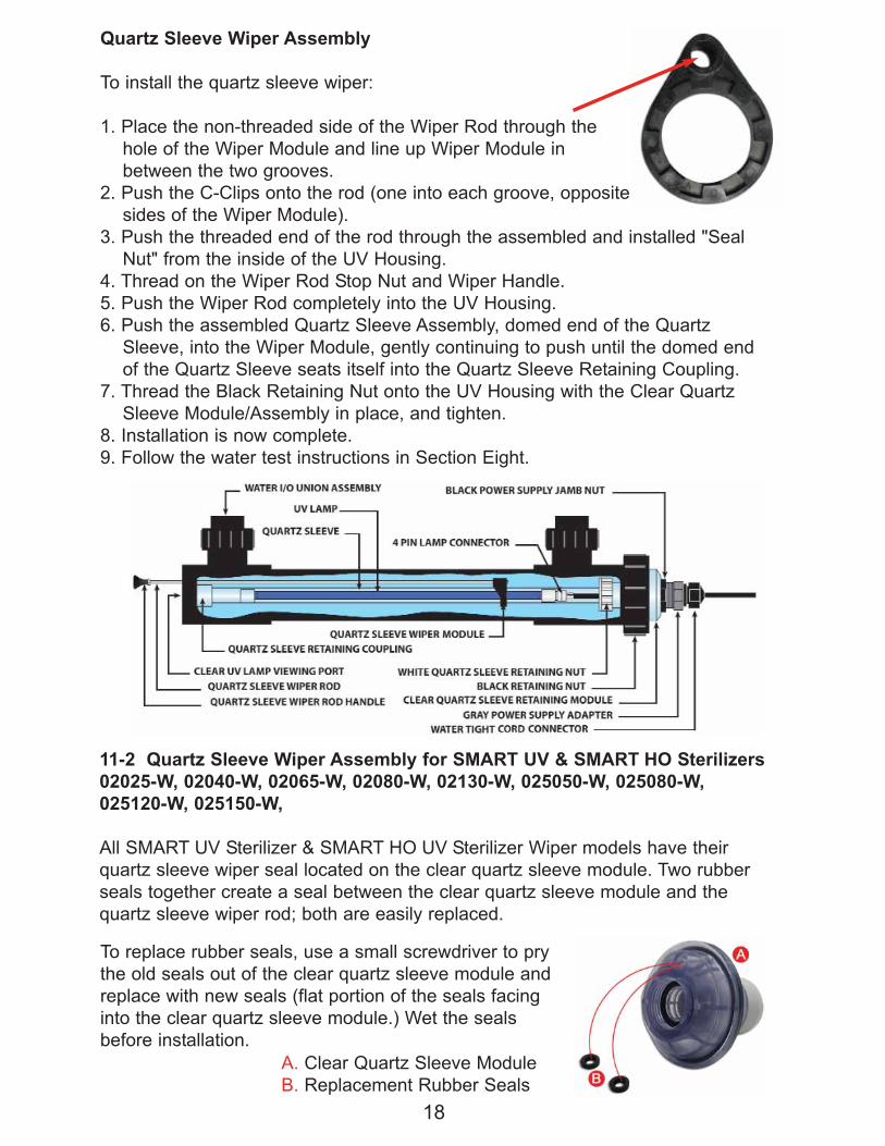
A. Clear Quartz Sleeve Module
B. Replacement Rubber Seals
18
Quartz Sleeve Wiper Assembly
To install the quartz sleeve wiper:
1. Place the non-threaded side of the Wiper Rod through the
hole of the Wiper Module and line up Wiper Module in
between the two grooves.
2. Push the C-Clips onto the rod (one into each groove, opposite
sides of the Wiper Module).
3. Push the threaded end of the rod through the assembled and installed "Seal
Nut" from the inside of the UV Housing.
4. Thread on the Wiper Rod Stop Nut and Wiper Handle.
5. Push the Wiper Rod completely into the UV Housing.
6. Push the assembled Quartz Sleeve Assembly, domed end of the Quartz
Sleeve, into the Wiper Module, gently continuing to push until the domed end
of the Quartz Sleeve seats itself into the Quartz Sleeve Retaining Coupling.
7. Thread the Black Retaining Nut onto the UV Housing with the Clear Quartz
Sleeve Module/Assembly in place, and tighten.
8. Installation is now complete.
9. Follow the water test instructions in Section Eight.
11-2 Quartz Sleeve Wiper Assembly for SMART UV & SMART HO Sterilizers
02025-W, 02040-W, 02065-W, 02080-W, 02130-W, 025050-W, 025080-W,
025120-W, 025150-W,
All SMART UV Sterilizer & SMART HO UV Sterilizer Wiper models have their
quartz sleeve wiper seal located on the clear quartz sleeve module. Two rubber
seals together create a seal between the clear quartz sleeve module and the
quartz sleeve wiper rod; both are easily replaced.
To replace rubber seals, use a small screwdriver to pry
the old seals out of the clear quartz sleeve module and
replace with new seals (flat portion of the seals facing
into the clear quartz sleeve module.) Wet the seals
before installation.

19
A. C-Clamp
B. Wiper Module (Holder)
C. Rubber Wiper (O-Ring)
Wiper Assembly Parts Breakdown
D. SS Wiper Rod
E. Rod Handle Stop Nut
F. Wiper Rod Handle
To install the Quartz Sleeve Wiper:
1. Place the non-threaded side of the Wiper Rod through the top hole
of the Wiper Module and line up the Wiper Module in between the
two grooves.
2. Push the C-Clips onto the Rod (one into each groove, opposite of Wiper Module)
3. Push the Domed End of the Quartz Sleeve through the Wiper Module that is
attached to the Wiper Rod.
4. Slide the Wiper Module w/ Rod attached two thirds up the Quartz Sleeve.
5. Push the Wiper Rod threaded end completely into and through the Quartz
Sleeve Module ¼" hole w/ Rubber Seals.
6. Thread on the Wiper Rod Stop Nut and Wiper Handle.
7. Push the Quartz Sleeve (open end) w/ White Retaining Nut, Quartz Sleeve
Rubber Gasket and O-ring into the Clear Quartz Sleeve Module respectively,
line-up properly and tighten down white nut (hand tight - See Section Six).
8. Gently slide the entire Quartz Sleeve/Wiper Assembly into the UV housing;
make sure the domed end of the Quartz Sleeve slides into the Quartz Sleeve
Coupling.
9. Thread the Black Retaining Nut onto the UV Housing with the Clear Quartz
Sleeve Module/Assembly in place, hand tighten only.
10. Installation is now complete.
11. Follow water test instructions (See Section Eight).
20
Section Twelve: SMART UV Installation/Operation
SMART UV Installation Locations
Our SMART UVs are used in a variety of applications to control waterborne
pathogens; we encourage you to consider the installation/operation
recommendations provided here.
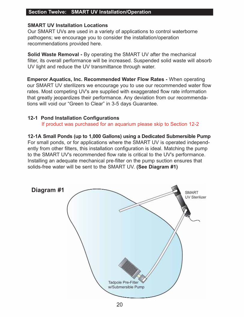
12-1 Pond Installation Configurations
If product was purchased for an aquarium please skip to Section 12-2
12-1A Small Ponds (up to 1,000 Gallons) using a Dedicated Submersible Pump
For small ponds, or for applications where the SMART UV is operated independ-
ently from other filters, this installation configuration is ideal. Matching the pump
to the SMART UV's recommended flow rate is critical to the UV's performance.
Installing an adequate mechanical pre-filter on the pump suction ensures that
solids-free water will be sent to the SMART UV. (See Diagram #1)
Solid Waste Removal - By operating the SMART UV after the mechanical
filter, its overall performance will be increased. Suspended solid waste will absorb
UV light and reduce the UV transmittance through water.
Emperor Aquatics, Inc. Recommended Water Flow Rates - When operating
our SMART UV sterilizers we encourage you to use our recommended water flow
rates. Most competing UV's are supplied with exaggerated flow rate information
that greatly jeopardizes their performance. Any deviation from our recommenda-
tions will void our “Green to Clear” in 3-5 days Guarantee.
Diagram #1

21
Diagram #2
12-1B Small to Moderately Sized Ponds (up to 5,000 Gallons) using
Skimmer and Falls
This is a very popular filter system style. Placing the UV between the skimmer box
and the bio-falls filter ensures that pre-filtered water reaches the UV, increasing its
performance while reducing maintenance. Often the capacity of the pump
exceeds the capacity of the UV, if this is the case, install a by-pass manifold. Be
sure that the skimmer is equipped with mechanical (solid waste removal) filtering
capacity. (See Diagram #2)
Note: Before gluing pipe or a reducer bushing into the UV's union or socket,
remove the quartz sleeve assembly to prevent glue from dripping onto the
quartz sleeve. Use Teflon tape on all threaded connections.
ball valve
true union ball valve

22
12-1C Larger Sized Ponds (above 5,000 Gallons)
Surface Skimmer/Pressurized Filter
This is one of the most efficient pond/exhibit filter system styles we can recom-
mend. This system is simple yet it achieves critical filtering goals, such as good
water circulation for increased solid waste suspension. The bottom drain/surface
skimming capabilities ensure maximum waste removal. (See Diagram #3)
Diagram #3
The SMART UV is positioned after the mechanical filter where it can receive only
solid waste free water, optimizing UV transmittance/performance. Notice the
3-way valve that regulates suction from the skimmer and drain to the pump,
allowing flow control. Next, multiple "clean water returns” improve circulation in
the pool suspending solid waste and helping it to find the filter. If you have a flow
rate that exceeds the UV’s, install a by-pass manifold. (See Diagram #2)
Note: Before gluing pipe or a reducer bushing into the UV's union or socket,
remove the quartz sleeve assembly to prevent glue from dripping onto the
quartz sleeve. Use Teflon tape on all threaded connections.
ball valves

23
12-2A Canister Filter/Aquarium Installation
Pressurized Canister filters are commonly used with small freshwater/saltwater
aquariums. This diagram shows our EA SMART UV Lite model. It is important to
match the Canister Filter’s flow rate to the capacity of the SMART UV. If this is not
feasible, use a by-pass manifold (See Diagram #6 on pg. 25). To prevent back-
siphoning, consider installing a check valve or ball valve (see filter manufacturer’s
instructions/recommendations). (See Diagram #4)
Diagram #4
Note: Before gluing pipe or a reducer bushing into the UV's union or socket,
remove the quartz sleeve assembly to prevent glue from dripping onto the
quartz sleeve. Use Teflon tape on all threaded connections.
24
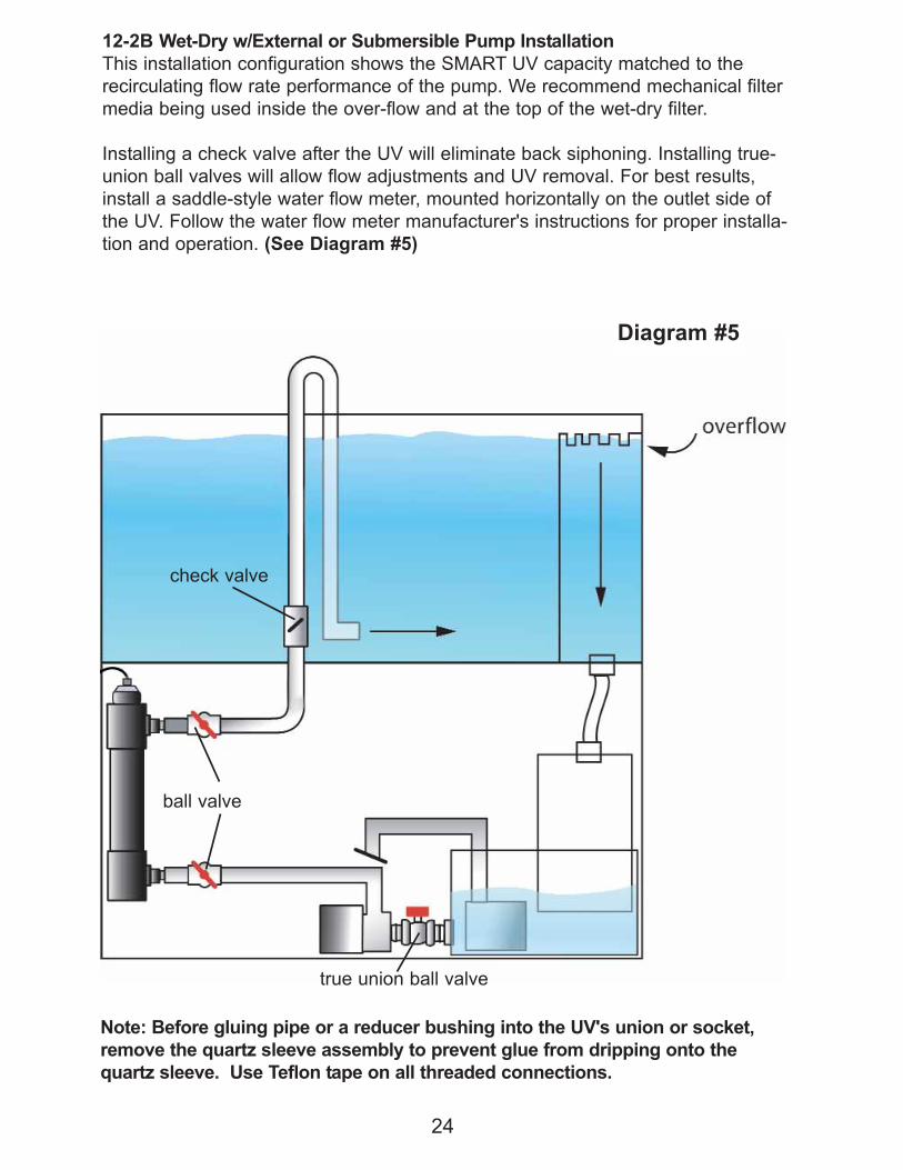
12-2B Wet-Dry w/External or Submersible Pump Installation
This installation configuration shows the SMART UV capacity matched to the
recirculating flow rate performance of the pump. We recommend mechanical filter
media being used inside the over-flow and at the top of the wet-dry filter.
Installing a check valve after the UV will eliminate back siphoning. Installing true-
union ball valves will allow flow adjustments and UV removal. For best results,
install a saddle-style water flow meter, mounted horizontally on the outlet side of
the UV. Follow the water flow meter manufacturer's instructions for proper installa-
tion and operation. (See Diagram #5)
Diagram #5
Note: Before gluing pipe or a reducer bushing into the UV's union or socket,
remove the quartz sleeve assembly to prevent glue from dripping onto the
quartz sleeve. Use Teflon tape on all threaded connections.
check valve
ball valve
true union ball valve

25
12-2C Wet-Dry w/External or Submersible Pump Installation
This installation configuration is identical to diagram 12-2B with the addition of a
bypass manifold. The bypass is used to deliver a precise water flow to the
SMART UV when the overall clean water return flow rate exceeds the UV's
capacity.
Installing a check valve after the UV will eliminate back siphoning. Installing true-
union ball valves will allow flow adjustments and easy UV removal for servicing.
For best results, install a saddle-style water flow meter, mounted horizontally on
the outlet side of the UV. Follow the water flow meter manufacturer's instructions
for proper installation and operation. (See Diagram #6)
Diagram #6
Note: Before gluing pipe or a reducer bushing into the UV's union or socket,
remove the quartz sleeve assembly to prevent glue from dripping onto the
quartz sleeve. Use Teflon tape on all threaded connections.
check valve
ball valve
true union
ball valve
true union ball valve

26
Section Thirteen: SMART UV Winterizing
13-1 Winterizing: Using the SMART UV in extremely cold temperatures can
cause damage to the unit, especially if the water is allowed to freeze inside the
equipment. Please note that damage to the product in this manner is not
covered under warranty.
13-2 We recommend shutting the SMART UV down when the temperature con-
sistently falls below 50 degrees.
13-3 Drain and remove the SMART UV from the filtration system.
13-4 Disassemble the entire unit and carefully clean both the outside and interior
of the SMART UV body and components.
13-5 Once clean and dry, store the SMART UV in a dry place for the winter.
Return the SMART UV to service when temperatures consistently return to 50
degrees or greater. Be sure to replace the quartz sleeve gasket/o-ring and per-
form a water test prior to operating the equipment. (See Section 6, 8, and 11)
14-1 Quartz Sleeve Cleaning: We recommend that the UV's quartz sleeve be
visually checked for cleaning once every three months of operation. Be aware that
even the slightest layer of material (slim/dirt) coated on the outside of the quartz
sleeve can have a profound affect on UV-C light transmittance through the glass
and into the water. Cleaning frequency is dependent on how well you are filtering
the water (solids removal) prior to the UV.
To clean the quartz sleeve, unplug the UV and shut the water pump off. Next,
unthread the UV's black retaining nut and gently remove the quartz sleeve assem-
bly and lamp from the UV housing. Inspect the quartz sleeve and clean as needed
with a soft, clean cloth. For calcium deposits,
use vinegar or muriatic acid to dissolve/clean.
Be sure to remove any cleaners or acid before
reassembling the quartz sleeve assembly and
lamp back into the UV housing.
14-2 UV lamps need to be replaced after 13
months (9,000 hours.) of continual use.
14-3 Lamp Connector Removal: In the event
that you would need to replace your 4-pin lamp
connector follow these steps:
Section Fourteen: SMART UV Maintenance
1. Unplug unit from power source.
2. Remove lamp from unit.
3. Unplug lamp from connector/power cord.

27
4. Grasp the white 4-pin lamp connector with a pair of pliers while standing on the
power cord itself.
5. Pull hard, the connector will come off.
6. Check to make sure the ends of electrical wires are still tinned; they are pre-
soldered before they’re pushed into the connector. If they are no longer tinned
you will need to dip them in some flux and then solder to make them firm
enough to push back in new lamp connector. (Note: Clean away any residual
flux off of the wires before assembling them into the lamp connector.)
7. Using a "new" 4-pin lamp connector, push the power cord's tinned wires into
the holes of the connector making sure that they are firmly attached. Once
attached, the wires should not pull out of the connector. (See diagrams below
for wire placement).
8. Plug lamp back into connector.
9. When installing the lamp be sure to have black jamb nut all the way back on
gray adapter. Tighten down the gray adapter first and then secure the black
jamb nut. (See Section Ten)
IMPORTANT: If you do not have the black jamb nut back far enough before
tightening the gray adapter, the gray adapter will not make contact with the power
supply gasket and damage from outside moisture may occur.
For this style power supply use wire
configuration A.
For this style power supply use wire
configuration B.
A B

28
Section Fifteen: SMART UV Replacement Parts
EMPEROR AQUATICS, INC.
SMART UV LITE STERILIZERS EXPLODED PARTS VIEW DIAGRAM
FOR MODEL #'s 02218, 02225, 02240, & 02280 UV STERILIZERS &
FOR MODEL #'s 02218-W, 02225-W, 02240-W, & 02280-W UV STERILIZERS
1. UV Lamp
2. 4-Pin Lamp Connector
3. Black Power Supply Jamb Nut
4. Gray Power Supply Adapter
5. Power Supply Cord
6. Power Supply Module Assembly
7. Black Retaining Nut
8. Power Supply Gasket
9. Clear Quartz Sleeve Retaining
Module
10. O-Ring for Clear Quartz Sleeve
Retaining Module
11. Quartz Sleeve O-Ring
12. Quartz Sleeve Gasket
13. White Quartz Sleeve Gasket/O
Ring Retaining Nut
14. Quartz Sleeve
15. UV Sterilizer Housing
16. Water Inlet/Outlet Union O-Ring (used onunion models only)
17. Water Inlet/Outlet Union Socket Half (used on
union models only)
18. Water Inlet/Outlet Union Retaining Nut (used
on union models only)
19. Hose Barb Insert (used on hose barb models
only)
20. Quartz Sleeve Wiper Module (only w/ Wiper
models)
21. C-Clips (only w/ Wiper models)
22. Quartz Sleeve Wiper Rod (only w/ Wiper
models)
23. Wiper Rod Handle Stop Nut (only w/ Wiper
models)
24. Wiper Rod Hanle (only w/ Wiper models)
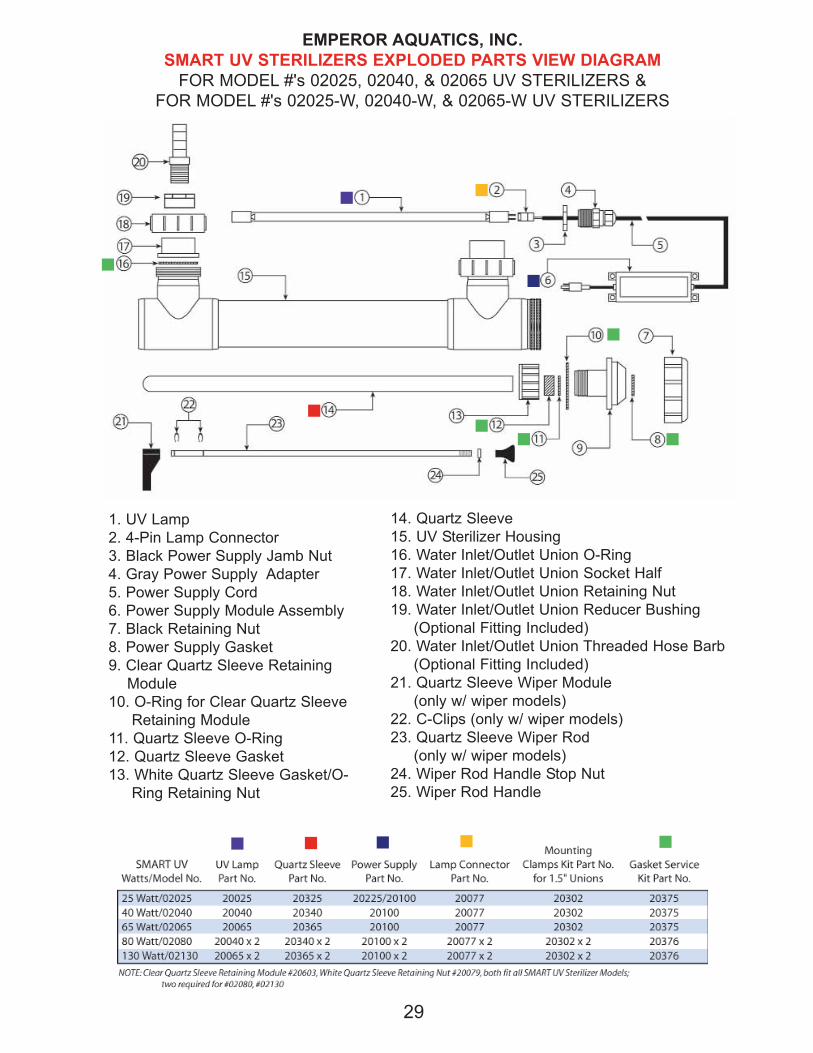
EMPEROR AQUATICS, INC.
SMART UV STERILIZERS EXPLODED PARTS VIEW DIAGRAM
FOR MODEL #'s 02025, 02040, & 02065 UV STERILIZERS &
FOR MODEL #'s 02025-W, 02040-W, & 02065-W UV STERILIZERS
1. UV Lamp
2. 4-Pin Lamp Connector
3. Black Power Supply Jamb Nut
4. Gray Power Supply Adapter
5. Power Supply Cord
6. Power Supply Module Assembly
7. Black Retaining Nut
8. Power Supply Gasket
9. Clear Quartz Sleeve Retaining
Module
10. O-Ring for Clear Quartz Sleeve
Retaining Module
11. Quartz Sleeve O-Ring
12. Quartz Sleeve Gasket
13. White Quartz Sleeve Gasket/O-
Ring Retaining Nut
14. Quartz Sleeve
15. UV Sterilizer Housing
16. Water Inlet/Outlet Union O-Ring
17. Water Inlet/Outlet Union Socket Half
18. Water Inlet/Outlet Union Retaining Nut
19. Water Inlet/Outlet Union Reducer Bushing
(Optional Fitting Included)
20. Water Inlet/Outlet Union Threaded Hose Barb
(Optional Fitting Included)
21. Quartz Sleeve Wiper Module
(only w/ wiper models)
22. C-Clips (only w/ wiper models)
23. Quartz Sleeve Wiper Rod
(only w/ wiper models)
24. Wiper Rod Handle Stop Nut
25. Wiper Rod Handle
29

30
EMPEROR AQUATICS, INC.
SMART UV STERILIZER EXPLODED PARTS VIEW DIAGRAM
FOR 80 & 130 WATT UV STERILIZERS
MODELS #02080 & 02130 & MODELS #02080-W & 02130-W
1. UV Lamp
2. 4-Pin Lamp Connector
3. Black Power Supply Jamb Nut
4. Gray Power Supply Adapter
5. Power Supply Cord
6. Power Supply Module Assembly
7. Black Retaining Nut
8. Power Supply Gasket
9. Clear Quartz Sleeve Retaining Module
10. O-Ring for Clear Quartz Sleeve
Retaining Module
11. Quartz Sleeve O-Ring
12. Quartz Sleeve Gasket
13. White Quartz Sleeve Gasket/O-Ring
Retaining Nut
14. Quartz Sleeve
15. UV Sterilizer Housing
16. Water Inlet/Outlet Union O-Ring
17. Water Inlet/Outlet Union Socket Half
18. Water Inlet/Outlet Union Retaining Nut
19. Water Inlet/Outlet Union Reducer Bushing
(optional fitting included)
20. Water Inlet/Outlet Union Threaded Hose
Barb (optional fitting included)
21. Quartz Sleeve Wiper Module (only with
Wiper models)
22. C-Clips (only w/ wiper models)
23. Quartz Sleeve Wiper Rod
(only w/ wiper models)
24. Wiper Rod Handle Stop Nut
25. Wiper Rod Handle
(See chart on pg. 29 for part numbers)

EMPEROR AQUATICS, INC.
SMART HO UV STERILIZERS EXPLODED PARTS VIEW DIAGRAM
FOR MODEL #'s 025050, 025080, 025120, & 025150 UV STERILIZERS &
FOR MODEL #'s 025050-W, 025080-W, 025120-W, & 025150-W UV STERILIZERS
1. UV Lamp
2. 4-Pin Lamp Connector
3. Black Power Supply Jamb Nut
4. Gray Power Supply Adapter
5. Power Supply Cord
6. Power Supply Module Assembly
7. Black Retaining Nut
8. Power Supply Gasket
9. Clear Quartz Sleeve Retaining Module
10. O-Ring for Clear Quartz Sleeve
Retaining Module
11. Quartz Sleeve O-Ring
12. Quartz Sleeve Gasket
13. White Quartz Sleeve Gasket/O-Ring
Retaining Nut
14. Quartz Sleeve
15. UV Sterilizer Housing
16. Water Inlet/Outlet Union O-Ring
17. Water Inlet/Outlet Union Socket Half
18. Water Inlet/Outlet Union Retaining Nut
19. Quartz Sleeve Wiper Module (w/ wiper only)
20. C-Clips (w/ wiper only)
21. Quartz Sleeve Wiper Rod (w/ wiper only)
22. Wiper Rod Handle Stop Nut (w/ wiper only)
23. Wiper Rod Handle (w/ wiper only)
31
32
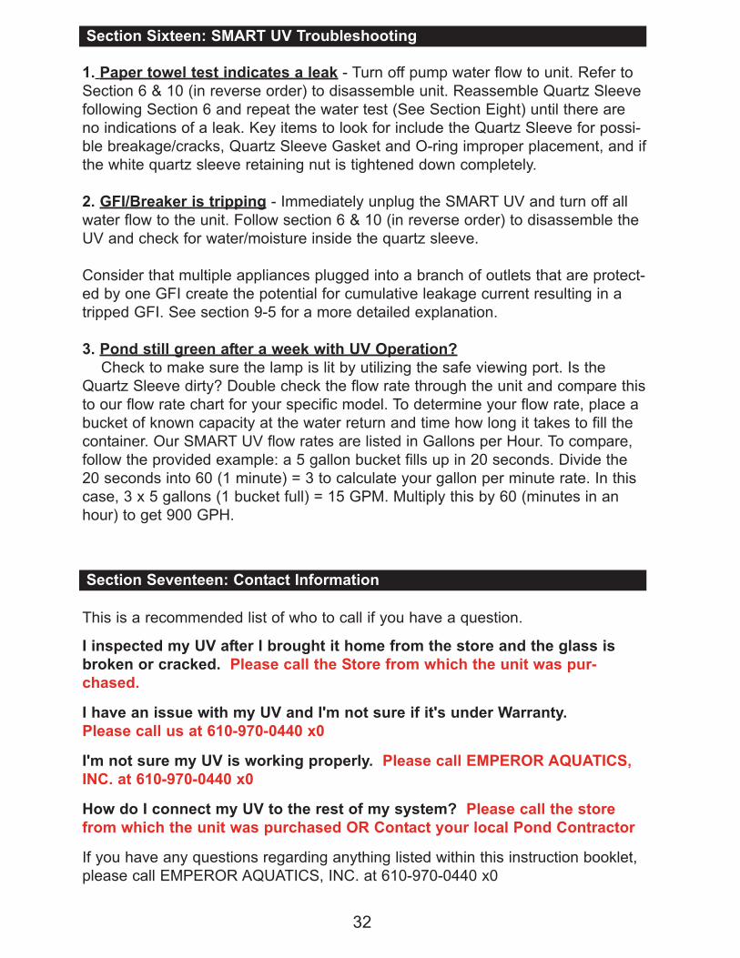
Section Sixteen: SMART UV Troubleshooting
1. Paper towel test indicates a leak - Turn off pump water flow to unit. Refer to
Section 6 & 10 (in reverse order) to disassemble unit. Reassemble Quartz Sleeve
following Section 6 and repeat the water test (See Section Eight) until there are
no indications of a leak. Key items to look for include the Quartz Sleeve for possi-
ble breakage/cracks, Quartz Sleeve Gasket and O-ring improper placement, and if
the white quartz sleeve retaining nut is tightened down completely.
2. GFI/Breaker is tripping - Immediately unplug the SMART UV and turn off all
water flow to the unit. Follow section 6 & 10 (in reverse order) to disassemble the
UV and check for water/moisture inside the quartz sleeve.
Consider that multiple appliances plugged into a branch of outlets that are protect-
ed by one GFI create the potential for cumulative leakage current resulting in a
tripped GFI. See section 9-5 for a more detailed explanation.
3. Pond still green after a week with UV Operation?
Check to make sure the lamp is lit by utilizing the safe viewing port. Is the
Quartz Sleeve dirty? Double check the flow rate through the unit and compare this
to our flow rate chart for your specific model. To determine your flow rate, place a
bucket of known capacity at the water return and time how long it takes to fill the
container. Our SMART UV flow rates are listed in Gallons per Hour. To compare,
follow the provided example: a 5 gallon bucket fills up in 20 seconds. Divide the
20 seconds into 60 (1 minute) = 3 to calculate your gallon per minute rate. In this
case, 3 x 5 gallons (1 bucket full) = 15 GPM. Multiply this by 60 (minutes in an
hour) to get 900 GPH.
Section Seventeen: Contact Information
This is a recommended list of who to call if you have a question.
I inspected my UV after I brought it home from the store and the glass is
broken or cracked. Please call the Store from which the unit was pur-
chased.
I have an issue with my UV and I'm not sure if it's under Warranty.
Please call us at 610-970-0440 x0
I'm not sure my UV is working properly. Please call EMPEROR AQUATICS,
INC. at 610-970-0440 x0
How do I connect my UV to the rest of my system? Please call the store
from which the unit was purchased OR Contact your local Pond Contractor
If you have any questions regarding anything listed within this instruction booklet,
please call EMPEROR AQUATICS, INC. at 610-970-0440 x0

SERVICE AND REPAIR
Your retailer or distributor is not an authorized service or repair center! If trouble
develops, do not take the unit back to your retail store. Instead, call Emperor Aquatics
Inc. at (610)-970-0440 x0 to discuss the problem then if necessary we will give you
an RMA number, so you may return the unit to us for proper service. After being
given an RMA number carefully pack the unit up to avoid shipping damage. Send the
unit to the following address:
DO NOT RETURN ANY PRODUCT WITHOUT PRIOR AUTHORIZATION
Be sure to insure your package prior to shipping it; clearly indicate the problem on
paper and place it in the box. Please provide your return address, as well as a day-
time phone number where you can be reached. Upon receipt of your unit, we will
repair or replace the unit (at no charge if the warranty is still in effect, proof of date of
purchase will be required) or call/send you an estimate of the cost of the repairs
which requires your authorization in order for us to proceed.
WARRANTY
EMPEROR AQUATICS, INC. warrants to the original purchaser of its
Ultraviolet Sterilizers to be free from defects in workmanship or materials for a period
of twelve (12) months from the date of purchase on the power supply and all gasket
seals. A lifetime warranty is offered on the UV Sterilizer's plastic main body housing
due to failure of the plastic from UV light exposure and 90 days on the UV lamp for
electrical operation only. The UV lamp and the Quartz Sleeve are not warranted
against breakage due to their glass construction. The equipment must be installed in
accordance with the factory instructions & operated within the environment and limi-
tations for which it was designed for warranty coverage. Should any of the integral
parts of the unit become defective within their time constraints from the date of pur-
chase, they will be repaired or replaced, if proven defective in workmanship or mate-
rial in the opinion of the manufacturer, This does not include damage by freezing or
the reuse of gasket seals that are more than twelve (12) months old.
Any costs incurred for the labor of removing the unit shall be the responsibility of the
original purchaser, as will be all shipping charges to and from Emperor Aquatic's Inc.
factory. Any non-warranty repair will be billed at a per hour rate, call for current rate
with a minimum of 1 hour plus the cost of the parts. Damage or failure of any part of
the UV Sterilizer covered by this warranty, which results from causes, directly or indi-
rectly, connected with the installation, operation, environment, use or willful abuse,
including, without limitation, improper packaging and damage incurred during ship-
ping is not covered by this warranty. Otherwise, any implied warranties, which
accompany the sale of these goods, are limited to their respective time constraints
from the date of purchase. The manufacturer will only be responsible for the repair or
replacement of any of its products or parts there of that are found to be defective and
will not bear the cost of any incidental or consequential damages arising out of the
occurrence of such a defect.
EMPEROR AQUATICS INC.
2229 SANATOGA STATION RD.
POTTSTOWN, PA 19464
33

34
Other Emperor Aquatics, Inc. Products
Each bioPRO features our unique Bio Cell
bio media; specifically designed for bio-
filtration. This neutrally buoyant, “high
impact” polystyrene media provides a large
amount of surface area that is required for
healthy colonies of aerobic nitrifying
bacteria. Bio Cell’s design combine self-
cleaning with protected surface area,
enhancing and protecting nitrifying bacteria
growth. The result: a biological filter specifically
engineered to deliver robust biofiltration…easy to
install…easy to operate!
Our Advanced UV for SAVIO
Skimmers is available in 18, 25 and
50 watt. This new UV was created
to work with the Savio skimmer’s
new interior design, which was
released in early 2007.
Our Original Retro-Fit UV for SAVIO
Skimmers is available in 16, 25 and
57 watt. All Retro-Fit UVs utilize our
“Hard Quartz” glass UV lamps which
deliver 13 months of continual use
until reaching 80% efficiency.
Model # - 01782
& 01786
Model # - 02826
Model # - 02825

A complete submersible filter system
for ponds up to 1,000 gallons
• Submersible, no plumbing
• Efficient & Easy to clean
• 500 GPH water pump
• Internal 25 watt UV
• Durable Construction
Model # - 01725
Combine with a SMART UV for complete
“small” pond filtration
• Large surface area for efficientsolid waste capture
• Easily attaches to the suctionend of water pump using standard PVC fittings
• Keeps pumps, fountains, UVsand filters free of clogging
• Easy to install and cleanModel # - 01703 & 01705
35
HydraPAK systems combine
exceptional solid waste capture/
removal with efficient UV protection
against nuisance waterborne algae
and harmful bacteria. Each component
of the HydraPAK is specifically matched
to provide dependable operating
performance. They are best suited for
ornamental ponds/water features,
mammal/reptile exhibits and fish
culture systems. Turn-key system;
complete and ready to go.
Model # - EAK-2

Notes:
2229 Sanatoga Station Road Pottstown, PA 19464
Phone: 610-970-0440 | Fax: 610-970-0443
Email: [email protected]
Empero
rAquatics-AQUARIUM.com
Register Online at:
OWNER'S REGISTRATION OF EQUIPMENT
FOR YOUR WARRANTY TO BE VALID YOU MUST SUBMIT A FILLED OUT
INFORMATION CARD OR COMPLETE AN ONLINE REGISTRATION FORM
WITHIN 30 DAYS OF PURCHASE.
PURCHASER'S NAME:
PHONE #: FAX #:
STREET ADDRESS:
CITY: STATE: _____ ZIP:
SERIAL #: MODEL #: PURCHASE DATE:
EMAIL ADDRESS:
(PLEASE PRINT)
HOW DO YOU LIKE OUR PRODUCT?
We at Emperor Aquatics take your comments about our products very
seriously. Please take a few moments to answer these questions and return
this form with your product registration.
1. Was this product packaged well?
2. Did you receive all of the parts and instructions with the unit?
3. Were the instructions easy to understand?
4. Were you satisfied with the quality of the product?
5. Are you satisfied with the product’s performance?
6. Would you recommend our products to someone else?
7. Where did you purchase the unit?
8. What did you pay for the unit?
9. Application
Other
Pond Aquarium