operating and maintenance manual vibratory pile …operating and maintenance manual vibratory pile...
TRANSCRIPT

OPERATING AND MAINTENANCE MANUAL
VIBRATORY PILE DRIVER/EXTRACTOR
WITH MODEL 325 POWER PACK
SERIAL NUMBERS: 182940 AND ABOVE OM-223/325-0295
SPECIALIZING IN PILE DRIVING EQUIPMENT
CORPORATE OFFICES: 301 WAREHOUSE DR., MATHEWS, NC 28105 PHONES: 800 438-9281 & 704 821-7681 TELEX 572385 ICE INTL


PREFACE This manual was prepared to acquaint the owner, operator and serviceman with the operation and maintenance of the vibratory driver/extractor. We suggest that this manual be carefully studied before operating or undertaking any maintenance work on the unit. This manual is organized into two major categories. The first category is for routine OPERATING INSTRUCTIONS of the unit and includes a GENERAL DESCRIPTION section, which presents a basic explanation of the driver/extractor and some of its specifications. The MAINTENANCE AND ADJUSTMENT section should be referred to periodically for normal servicing of equipment. All machines and equipment require systematic, periodic inspection and maintenance, if they are to perform satisfactorily, over a long period of time. The driver/extractor is primarily a vibrating machine and if not given the best of care, or if improperly used and maintained, it is self-destructive. Therefore, the unit should receive at least the same care and maintenance as other high quality construction equipment. The second category is for parts reordering and it includes both a PARTS LIST and a pictorial drawing of the assembly, for easier determination of the required part. Refer to the ORDERING PARTS section of the PARTS LIST for more specific procedures regarding parts ordering. Adherence of the listed procedures will insure receipt of the required part(s) with the minimal amount of delay or error.


WARRANTY
INTERNATIONAL CONSTRUCTION EQUIPMENT STANDARD WARRANTY International Construction Equipment (ICE) warrants new products sold by it to be free from defects in material or workmanship for a period of 90 days after date of delivery to the first user and subject to the following conditions: ICE's obligation and liability under this WARRANTY is expressly limited to repairing or replacing, at ICE's option, any parts which appear to ICE, upon inspection, to have been defective in material or workmanship. Such parts shall be provided at no cost to the user, at the business establishment of ICE or the authorized ICE distributor of the product, during regular working hours. This WARRANTY shall not apply to component parts or accessories of products not manufactured by ICE and which may carry the warranty of the manufacturer thereof, or to normal maintenance (such as engine tune-up) or to normal maintenance parts (such as oil filters). Replacement or repair parts installed in the product covered by this WARRANTY are warranted only for the remainder of the warranty, as if such parts were original components of said product. ICE COMPANY MAKES NO OTHER WARRANTY, EXPRESS OR IMPLIED, AND MAKES NO WARRANTY OF MERCHANTABILITY OR FITNESS, FOR ANY PARTICULAR PURPOSE. ICE's obligation under this WARRANTY shall not include any transportation charges, cost of installation, duty, taxes or any other charges whatsoever, or any liability for direct, indirect, incidental, or consequential damage of delay. If requested by ICE, products or parts for which a warranty claim is made are to be returned, transportation prepaid to ICE. Any improper use, including operation after discovery of defective of worn parts, operation beyond rated capacity, substitution of parts not approved by ICE or any alteration or repair by others in such manner as in ICE's judgement affects the product materially and adversely, shall void this WARRANTY. NO EMPLOYEE OR REPRESENTATIVE IS AUTHORIZED TO CHANGE THIS WARRANTY IN ANY WAY OR GRANT ANY OTHER WARRANTY UNLESS SUCH CHANGE IS MADE IN WRITING AND SIGNED BY AN OFFICER OF ICE.
TABLE OF CONTENTS
OPERATING INSTRUCTIONS I. GENERAL DESCRIPTION PAGE A. General I- 1 B. Vibrator I- 2 C. Hydraulic Clamp Head I- 2 D. Power Unit I- 2 E. Remote-Control Pendant I- 3 F. Specifications I- 3 II. PREPARATION FOR OPERATING A. General II- 1 B. Safety Precautions II- 1 C. Rigging of Vibrator II- 2 D. Connection of Hydraulic Clamp II- 2 E. Connection of Hydraulic Hoses II- 3 F. Bleeding Hydraulic Clamp Hoses II- 5 G. Filling Vibrator Pressure Hose II- 5 III. OPERATING INSTRUCTIONS A. Completion of Set-Up and Maintenance III- 2 B. Control Panel III- 2 C. Starting and Warming Up Engine III- 3 D. Warming Hydraulic Fluid III- 3 E. Operation of Remote-Control Pendant III- 4 F. Changing Frequency III- 5 G. Shutdown III- 6 IV. MAINTENANCE AND ADJUSTMENTS A. General IV- 1 B. Daily IV- 1 C. 100 Hours, 500 Hours and Other IV- 2 D. Annually IV- 2 E. Severe Conditions IV- 3 F. Lubrication IV- 3 G. Capacities IV- 7 H. Draining and Filling Hydraulic Fluid Reservoir IV- 8 I. Changing Hydraulic Return Filter Element IV- 8 J. Bolt Torque Information IV- 9

TABLE OF CONTENTS
OPERATING INSTRUCTIONS (CONTINUED) V. HYDRAULIC CIRCUITRY PAGE A. Hydraulic Clamp V- 1 B. Vibrator Drive V- 1 C. Auger Drive V- 3 D. Hydraulic Impact Hammer V- 3 E. Other V- 3 Hydraulic Schematic V- 4 F. Hydraulic Components List V- 5 VI. ELECTRICAL CIRCUITY A. Diesel Engine VI- 1 B. Hydraulic Clamp VI- 2 C. Vibrator VI- 2 D. Other VI- 2 Electrical Schematic VI- 3 E. Electrical Components List VI- 4 Electrical Diagram VI- 5
PARTS LIST VII. GENERAL DATA A. Abbreviations VII- 1 B. Screws and Bolts VII- 1 C. Serial Number Locations VII- 2 VIII. ORDERING PARTS A. Procedure VIII- 1 B. Fitting Description Key VIII- 2 Fitting Style Selector Chart - SC1 VIII- 3 C. Hose Description Code VIII- 4 D. Parts Identification VIII- 5 Parts Lists and Drawings VIII-6 thur VIII-35 E. Miscellaneous Accessories VIII-36 thru VIII-39 F. Recommended Spare Parts VIII-40 and VIII-41


I. GENERAL DESCRIPTION A. GENERAL The ICE Model 223 is a medium-frequency vibratory pile driver/extractor designed
to drive and extract sheet, pipe, timber and concrete piles, caisson pipe and H, I and wide-flange beams.
The Model 223 operates in a frequency range of 1050 to 2300 vibrations per
minute to provide maximum pile penetration rates in a wide variety of soils. The unit has an eccentric moment of 2200 inch-pounds and operates with an amplitude of 1/4 to 3/4 inch.
The vibratory driver unit consists of two major components. (1) The vibrator with
attached clamp and (2) the power unit with remote control pendant.
I-1
REMOTE CONTROL PENDANT
OIL COOLER
POWER UNIT
DRIVE & CLAMP PUMPS
FUEL TANK
DRIVE MANIFOLD
VIBRATION SUPPRRESSOR
HYDRAULIC MOTOR
VIBRATION CASE
ELASTOMERS
DESIEL ENGINE
CONTROL PANEL
MULTI-PUMP DRIVE
DRIVER / EXTRACTOR
CLAMP MANIFOLD
OIL RESERVOIR
ECCENTRIC WEIGHTS
CLAMP CYLINDER
CLAMP BODY

I. GENERAL DESCRIPTION B. VIBRATOR The vibrator consists of two major components. (1) The vibration case and (2)
the vibration suppressor. The vibration case contains two eccentric weights which rotate in a vertical plane
to create vibration. The eccentric weights are driven by a hydraulic motor mounted on the vibration case. The motor and two eccentrics are all gear connected to maintain proper synchronization. The eccentric and motor shafts are mounted in heavy-duty cylindrical roller bearings. Lubrication is provided by a splash system activated by the rotating eccentrics and gears.
A suppressor assembly is mounted to the top of the vibration case, to isolate
vibration from the crane and permit pile extraction. A, heavy, outer suppressor housing is connected to the vibration case by sixteen (16) rubber elastomers. Up to forty (40) tons of crane line pull may be applied to this suppressor during extraction.
C. HYDRAULIC CLAMP A hydraulic clamp, bolted to the bottom of the vibration case, transmits vibration to
the piling. The hydraulic clamp contains two gripping jaws; one fixed and one moveable. A large hydraulic cylinder operates the moveable jaw with 120 tons of force to grip the pile. Clamping and un-clamping occurs in a few seconds.
D. POWER UNIT The Model 325 power unit for the Model 223 vibrator is powered by a Caterpillar
3306TA diesel engine. The diesel engine develops 325 HP at 2200 RPM, which drives 3 hydraulic pumps that create the hydraulic pressures to operate the 223 vibrator motors and hydraulic clamp.
The totally enclosed power unit is mounted on a skid-type fuel tank sub-base. A
Control panel at the side of the unit contain all operating gages and controls. A common reservoir supplies hydraulic fluid to three separate hydraulic pumps - two for the vibrator motors and one for the hydraulic clamp.
Three hydraulic hoses, 100 feet in length, connect the power unit to the hydraulic
motors on the vibrator. Two other hydraulic hoses run from the power unit to the hydraulic clamp.
I-2
I. GENERAL DESCRIPTION E. REMOTE-CONTROL PENDANT
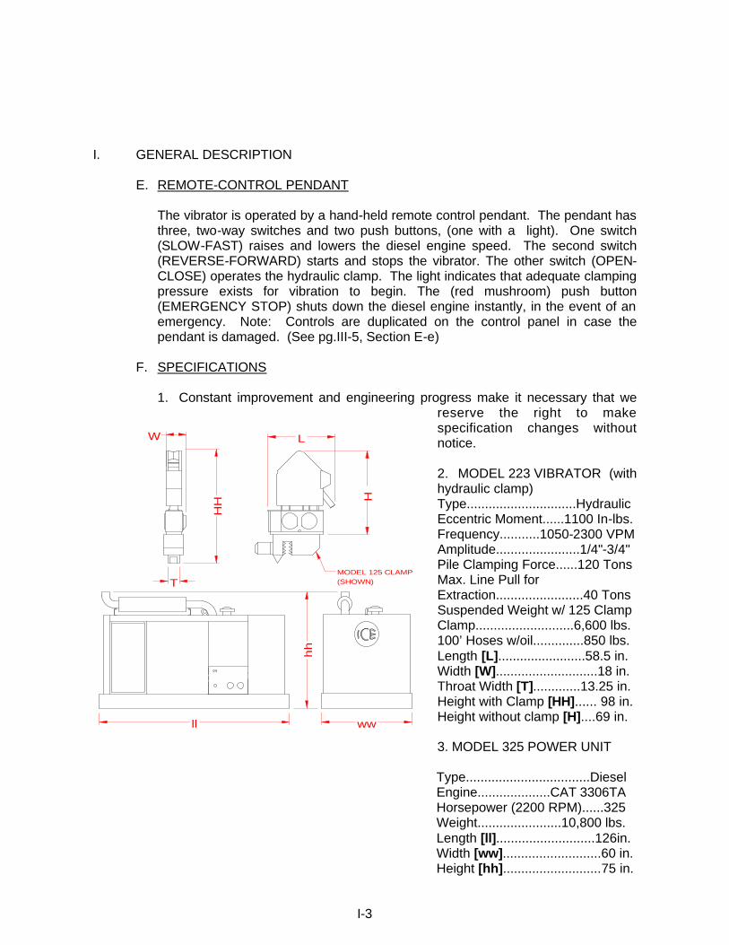
The vibrator is operated by a hand-held remote control pendant. The pendant has three, two-way switches and two push buttons, (one with a light). One switch (SLOW-FAST) raises and lowers the diesel engine speed. The second switch (REVERSE-FORWARD) starts and stops the vibrator. The other switch (OPEN-CLOSE) operates the hydraulic clamp. The light indicates that adequate clamping pressure exists for vibration to begin. The (red mushroom) push button (EMERGENCY STOP) shuts down the diesel engine instantly, in the event of an emergency. Note: Controls are duplicated on the control panel in case the pendant is damaged. (See pg.III-5, Section E-e)
F. SPECIFICATIONS 1. Constant improvement and engineering progress make it necessary that we
reserve the right to make specification changes without notice. 2. MODEL 223 VIBRATOR (with hydraulic clamp) Type..............................Hydraulic Eccentric Moment......1100 In-lbs. Frequency...........1050-2300 VPM Amplitude.......................1/4"-3/4" Pile Clamping Force......120 Tons Max. Line Pull for Extraction........................40 Tons Suspended Weight w/ 125 Clamp Clamp...........................6,600 lbs. 100’ Hoses w/oil..............850 lbs. Length [L]........................58.5 in. Width [W]............................18 in. Throat Width [T].............13.25 in. Height with Clamp [HH]...... 98 in. Height without clamp [H]....69 in. 3. MODEL 325 POWER UNIT Type..................................Diesel Engine....................CAT 3306TA Horsepower (2200 RPM)......325 Weight.......................10,800 lbs. Length [ll]...........................126in. Width [ww]...........................60 in. Height [hh]...........................75 in.
I-3
ll ww
T
hh
MODEL 125 CLAMP(SHOWN)
W
HH H
L
II. PREPARATION FOR OPERATION A. GENERAL
When unloading and unpacking the vibratory driver, use extreme care. For your protection, make a thorough inspection of the unit immediately on delivery. In case of any damage or shortage, notify the transit agent at once and have the delivering carrier make a notation on the freight bill.
B. SAFETY PRECAUTIONS
Safety is basically common sense. There are standard safety rules, but each situation has its own peculiarities which can not always be covered by rules. Therefore, your experience and common sense will be your best guide to safety. Be ever watchful for safety hazards and correct deficiencies promptly.
Use the following safety precautions as a general guide to safe operations: 1. When operating in a closed area, pipe exhaust fumes outside. Continued
breathing of exhaust fumes may be fatal. 2. When servicing batteries, do not smoke or use an open flame in the
vicinity. Batteries generate explosive gas during charging. There must be proper ventilation when charging batteries.
3. When filling fuel tank, do not smoke or use open flame in the vicinity. 4. Be extremely careful when using a carbon tetrachloride fire extinguisher in
a closed area as it produces toxic vapor. Provide adequate ventilation before entering a closed area where carbon tetrachloride has been used.
5. Never adjust or repair the unit while it is in operation. 6. Never operate the diesel engine with the governor linkage disconnected to
control the fuel rack. 7. Remove all tools and electrical cords before starting. 8. Store oily rags in containers. 9. Never store flammable liquids near the engine.
REMEMBER, SAFETY IS EVERYONE'S BUSINESS.
II-1

II. PREPARATION FOR OPERATION C. RIGGING OF VIBRATOR
A steel wire rope sling must be connected to the lifting pin of the vibration suppressor. The required strength of this sling depends on the capacity of the crane and the work to be carried out. A safety factor of five is recommended. Several turns of a smaller diameter cable will usually last longer than one turn of a larger diameter cable.
D. CONNECTION OF HYDRAULIC CLAMP
The vibrator is usually shipped with the hydraulic clamp already attached.
If the clamp is not attached, it will be necessary to attach it to the bottom of the vibrator. Orient the clamp to the vibrator with the clamp cylinder end (movable jaw) at the opposite end of the vibrator as the hose chute is mounted. All eight (1.5-6UN x 5.00) bolts must be in place and torqued to approximately 2800 ft.lbs. To do this place a pipe over the end of the Allen wrench to provide a six-foot lever arm. Have two men tighten each bolt.
For caisson work, the caisson beam must be attached to the bottom of the vibrator and tightened as above. Then slide the clamps into position on the caisson beam.
II-2
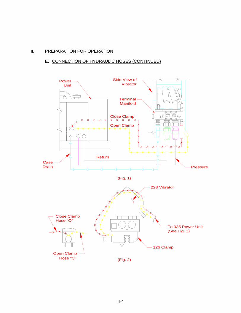
II. PREPARATION FOR OPERATION E. CONNECTION OF HYDRAULIC HOSES 1. Connection of hoses at power unit.
a. The vibrator and hydraulic clamp are connected to the power unit by five hydraulic hoses (Fig. 1) on the next page.
CAUTION: The power unit must be shut down during connection of the
hydraulic hoses.
b. The hoses connect to the power unit with quick-disconnect couplers. Hose couplers are arranged to insure correct connections at the power unit. See the diagram (Fig. 1) for correct hose connection.
c. Clean couplers with a lint-free cloth before making connections.
d. Make sure that the couplers are fully run up. They should be fully hand
tight. Do not use wrenches to tighten. 2. Connection of hoses at vibrator.
a. The vibrator is usually shipped with the hoses attached to the vibrator. If the hoses have been shipped separately, they must be connected in the field. Fig. 1 shows the correct arrangement of the five hoses connecting the power unit to the vibrator.
CAUTION: Starting the vibrator with the hoses reversed will result in low
power or possible ruptured hoses.
b. The vibrator is usually shipped with the hydraulic clamp and hoses attached. If the clamp has been shipped separately, the two hoses connecting the clamp to the vibrator must be connected. Fig. 2 on the next page shows the correct arrangement of these hoses.
For caisson clamps, four hoses must be connected. The “swivel tees” must be installed in the clamp lines, on top of the terminal manifold. This allows the four hoses to run to both sides of the vibrator and operate the caisson clamps. The terminal manifold is stamped O and C (O for Open Clamp) (C for Close Clamp).
II-3
II. PREPARATION FOR OPERATION E. CONNECTION OF HYDRAULIC HOSES (CONTINUED)
II-4
Hose "C"Open Clamp
(See Fig. 1)
(Fig. 2)
Close Clamp
126 Clamp
Hose "O"
Open Clamp
DrainCase
(Fig. 1)
To 325 Power Unit
Close Clamp
Return
Side View ofVibrator
Pressure
TerminalManifold
UnitPower
223 Vibrator

II. PREPARATION FOR OPERATION F. BLEEDING HYDRAULIC CLAMP HOSES
1. When the vibrator and hydraulic clamp are shipped with all hoses attached (between vibrator and clamp and five main hoses connected to the vibrator), the hoses are usually full of fluid and may be used immediately. However, if any of the clamp hoses are connected at the jobsite or if air is present in hoses, they must be bled prior to operation.
2. Read SECTION III - OPERATING INSTRUCTIONS.
3. Start and warm up the diesel engine in accordance with SECTION III-C -
STARTING AND WARMING UP ENGINE.
4. With the engine warmed-up and running at 1500 RPM, loosen the close-clamp line at the hydraulic clamp. Turn the clamp switch on the remote-control pendant to CLOSE. Wait until fluid flows from the connection at the hydraulic clamp. When fluid flows without air, tighten the connection.
5. After the line has been bled, alternately turn the clamp switch to CLOSE and OPEN to insure that the clamp is working properly. It may be necessary to bleed the line more than once. The open-clamp line may also require bleeding.
G. FILLING VIBRATOR PRESSURE HOSE
1. The vibrator is usually shipped with the vibrator hydraulic hoses full of fluid and the unit may be used immediately. However, if the pressure hose has been removed from the vibrator, the hose should be allowed to fill with hydraulic fluid prior to full speed operation.
2. Read SECTION III - OPERATING INSTRUCTIONS.
3. Start and warm up the diesel engine in accordance with SECTION III-C - STARTING AND WARMING UP ENGINE. Hold the vibrator in a vertical position.
4. With the engine warmed up and running at 1500 RPM, turn and hold the vibrator switch to REVERSE. The hoses will fill in approximately 5 minutes. CAUTION: If vibration begins in the vibrator, stop immediately and recheck hose connections.
II-5

III. OPERATING INSTRUCTIONS CONTROL PANEL WITH REMOTE CONTROL-PENDANT
III-1
DRIVE - FORWARD
BRAKE - REVERSE
CLOSE
OPEN
TACHOMETER
ENG OIL PRESS.
ENG WATER TEMP.
AMMETER
HOUR METER
HYD FLUID COLD
MAIN POWER
ONSTOP START
CLOSE
CLAMP
OPEN CLOSE
FOR.OFF
REV.
ENGINE THROTTLE
REMOTE - LOCAL
FOR.OFF
REV.
CLOSEOPEN
CLOSE
EMERGENCY STOP
j ag f
k
l
m
n
i
r
FASTSLOW
s
y
z
x
REMOTE - CONTROLPENDANT
(Fig. 1)
c
x
y
z
INSTRUCTIONSOPERATIONS AND MAINTENANCE
bd
e
h
o
III. OPERATING INSTRUCTIONS A. COMPLETION OF SET-UP AND MAINTENANCE
1. Complete all preparation as described in Section II.
2. Read Section IV - MAINTENANCE AND ADJUSTMENTS and perform any required maintenance.
B. CONTROL PANEL
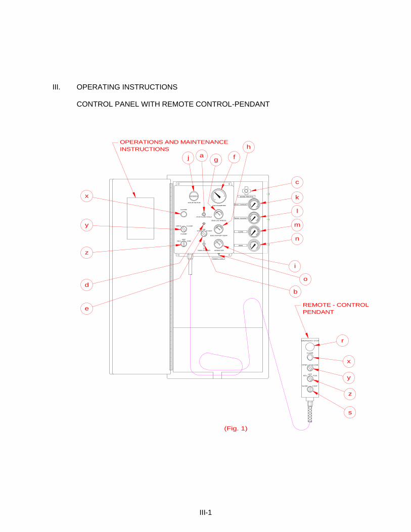
1. The control box (Fig. 1, page III-1) at the side of the power pack contains the controls and gages for the diesel engine, vibrator, and the OPERATION AND MAINTENANCE INSTRUCTIONS.
2. Control panel contains the following controls and gages:
a. Hydraulic fluid cold light - comes on if hydraulic fluid is below 60 deg. F
(16 deg. C). b. Main power switch (Circuit Breaker) - on/off switch for 24 volt electrical
power. Must be "ON" for the vibrator to run. c. Engine throttle. d. Engine shut-down reset button - on start must be held in until oil pressure
exceeds 30 PSI. e. Engine "ON/OFF/START" switch - for diesel engine. f. Engine tachometer. g. Engine oil pressure gage. h. Engine water temperature gage. i. Engine ammeter. j. Engine hourmeter. k. Pressure gage - (Drive - Forward). l. Pressure gage - (Brake - Reverse). m. Pressure gage - (Close). n. Pressure gage - (Open). o. Remote-Local switch. r. Emergency Stop - Push to stop engine s. Electric Throttle x. Clamp light. y. Clamp switch. z. Vibrator switch.
3. The OPERATION AND MAINTENANCE INSTRUCTIONS on the control panel
are there as reminders only. They are not complete and therefore not intended to substitute for a thorough understanding of this Operating Manual.
III-2
C. STARTING AND WARMING UP ENGINE
1. Before starting the engine, read the CATERPILLAR OPERATION GUIDE carefully. Follow the engine starting, operating and maintenance procedures in that manual.
2. The diesel engine should not be started if the temperature of the hydraulic
fluid is below 0 deg F. The temperature may be read on the gage on the hydraulic reservoir. If ambient temperatures below 0 deg. F are anticipated, an immersion heater for the hydraulic fluid is available. Consult ICE for details.
3. The MAIN SWITCH on the control panel should be ON. The vibrator switch
(FOR/REV) on the control pendant should be in the neutral position.
4. Pull out the ENGINE THROTTLE about half way. Press the button on the end of the throttle for adjustment.
5. Hold SHUTDOWN RESET button in and turn the ENGINE START switch
to START position. If the engine fails to start after 30 seconds of cranking, allow the starter to cool for two minutes before repeating the starting procedure.
6. As the engine starts, release the ENGINE START switch. It will return to
the RUN position.
7. Adjust the throttle until the engine is running at 1500 RPM and allow to warm-up for five minutes.
8. Allow the temperature of the hydraulic fluid to come up to at least 30 deg. F
before starting vibrator. D. WARMING HYDRAULIC FLUID
1. The vibrator should not be operated at full speed if the temperature of the hydraulic fluid is below 60 deg. F. The HYDRAULIC FLUID COLD light on the control panel will be on if fluid temperature is below 60 deg. F. Also check gage on reservoir.
2. If temperature of the hydraulic fluid is below 60 deg. F, set the diesel
engine at 1500 RPM and run the vibrator at reduced speed until the temperature of the hydraulic fluid exceeds 60 deg. F. The Hydraulic Fluid Cold light will then go off.
III-3

III. OPERATING INSTRUCTIONS D. WARMING HYDRAULIC FLUID (CONTINUED)
3. When the engine is warmed up and hydraulic fluid temperature is at least 60 deg. F, full speed operation may begin. Adjust the throttle so the engine is running at 2420 RPM unloaded. The engine should maintain about 2200 RPM under load.
CAUTION: Do not operate the vibrator if hydraulic fluid temperature
exceeds 160 deg. F as this may damage hydraulic components. E. OPERATION OF REMOTE-CONTROL PENDANT
1. The operation of the vibratory driver is controlled by the remote-control pendant. The pendant is connected to the control cabinet with 50 feet of electrical cable to permit operation from any advantageous position to view the vibrator. (Consult ICE for pendent extensions)
2. The pendant has three, two-way switches, an indicator light and an
EMERGENCY STOP button.
a. To Clamp to Pile:
Position vibratory driver on pile. Turn the clamp switch on the pendant to CLOSE. The CLAMP light on the pendant will come on when the hydraulic clamp has achieved adequate pressure to permit vibration to begin. The light should normally come on in a few seconds.
b. To Start Vibration:
Turn the vibrator switch to FORWARD.
NOTE: The vibrator switch reads FORWARD/REVERSE instead of
START/STOP because the Model 325 power unit also operates ICE earth augers.
CAUTION: Do not turn the switch to FORWARD until the CLAMP light in
the pendant comes on, indicating adequate clamping pressure.
c. To Stop Vibration:
Turn the vibrator switch to OFF.
NOTE: Accidentally turning the switch to REVERSE normally has no effect and will not cause damage.
III-4

III. OPERATING INSTRUCTIONS E. OPERATION OF REMOTE-CONTROL PENDANT (CONTINUED)
d. To Unclamp from Pile:
Turn the CLAMP switch to OPEN to release the hydraulic clamp so that the vibrator can be moved from the pile. Hold the CLAMP switch in the open position until the jaws are fully open.
CAUTION: Do not turn the switch to OPEN until a visual check indicates
that vibration has stopped.
e. To change engine speed:
Turn the Throttle switch (SLOW-FAST) to SLOW and the engine speed will decrease. Turn the switch to FAST and the engine speed will increase. Momentarily turning the throttle switch to FAST or SLOW during operations will adjust engine speed, and therefore vibrator speed, to facilitate the desired penetration rate.
f. Emergency stop button:
Push the EMERGENCY STOP button in and all operating functions will cease to operate. Diesel engine and vibrator will stop immediatally.
g. If the remote control pendant is damaged or the pendant line is cut, you may
still operate the vibrator by using the control switches on the control panel (See Fig. 1 on page III-1 items X, Y, Z). On the lower right bottom of the control panel there is a switch labeled "REMOTE-LOCAL". Turn the switch to LOCAL and the switches on the control panel will be functional, and the Remote Control Pendant will be disabled. Engine speed must be adjusted manually.
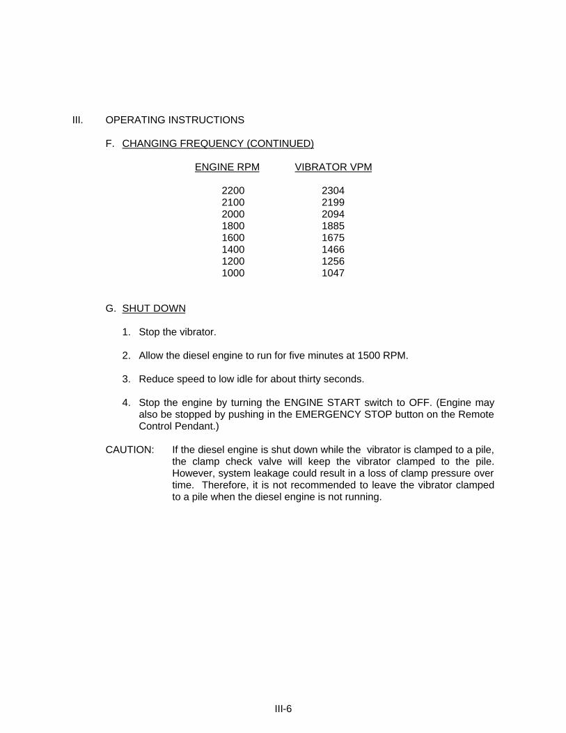
F. CHANGING FREQUENCY
1. In order to provide maximum flexibility in achieving optimum pile penetration and extraction rates, the frequency of the vibratory driver is adjustable.
2. The frequency can be varied from 1050 to 2300 vibrations per minute by
changing engine speed. Engine speed is changed with the ENGINE THROTTLE on the control panel or electric throttle switch (SLOW-FAST) on the remote control pendant. Vibrator frequency corresponds to engine speed according to the table shown on the next page:
III-5
III. OPERATING INSTRUCTIONS F. CHANGING FREQUENCY (CONTINUED)
ENGINE RPM VIBRATOR VPM
2200 2304 2100 2199 2000 2094 1800 1885 1600 1675 1400 1466 1200 1256 1000 1047
G. SHUT DOWN
1. Stop the vibrator.
2. Allow the diesel engine to run for five minutes at 1500 RPM.
3. Reduce speed to low idle for about thirty seconds.
4. Stop the engine by turning the ENGINE START switch to OFF. (Engine may also be stopped by pushing in the EMERGENCY STOP button on the Remote Control Pendant.)
CAUTION: If the diesel engine is shut down while the vibrator is clamped to a pile,
the clamp check valve will keep the vibrator clamped to the pile. However, system leakage could result in a loss of clamp pressure over time. Therefore, it is not recommended to leave the vibrator clamped to a pile when the diesel engine is not running.
III-6

IV. MAINTENANCE AND ADJUSTMENTS A. GENERAL
Preventive maintenance includes normal servicing that will keep the vibratory driver,clamp,and power unit in peak operating condition and prevent unnecessary trouble from developing. This servicing consists of periodic lubrication and inspection of the moving parts and accessories of the unit. Lubrication is an essential part of protective maintenance, controlling to a great extent the useful life of the unit. Different lubricants are needed and some components in the unit require more frequent lubrication than others. Therefore, it is important that the instructions regarding types of lubricants and frequency of their applications be closely followed. To prevent minor irregularities from developing into serious conditions that might involve shut-down and major repair, several other services or inspections are recommended for the same intervals as the periodic lubrications. The purpose of these services or inspections is to assure the uninterrupted operation of the unit. Thoroughly clean all lubrication fittings, caps, filler and level plugs and their surrounding surfaces before servicing. Prevent dirt from entering with lubricants and coolants. The intervals given in the schedule are based on normal operation. Perform these services, inspections, etc., more often as needed for operation under abnormal or severe conditions.
B. DAILY
1. Check the entire unit prior to and during set-up each day or at the beginning of each shift.
2. Prior to starting the power unit or at the beginning of each shift, check the following items:
a. Visibly inspect all bolts, nuts and screws including the bolts fastening the
hydraulic clamp to the vibration case to insure they are tight. IMPORTANT: vibration loosens bolts- check carefully.
b. Tighten bolts holding gripping jaws in hydraulic clamp. c. Grease plunger in hydraulic clamp with any good multi-purpose grease. d. Check the oil level in the vibration case and add oil if required. The oil
level should be in the middle of the sight glass. Change oil If milky or contaminated.
e. Check the fluid level in the hydraulic reservoir and refill if necessary. f. Check oil level, with dipstick, in the multi-pump drive.
IV-1

IV. MAINTENANCE AND ADJUSTMENTS B. DAILY (CONTINUED)
CAUTION: It is absolutely imperative that no dirt or other impurities be permitted to contaminate the hydraulic fluid. Any contamination will drastically shorten the life of the high-pressure hydraulic system.
f. Visually check all hoses for signs of damage or cuts that might cause hose
failure during operation. Be sure all connections are tight, especially the quick-disconnect couplers.
g. Visually inspect all suppressor elastomers. h. Electrical components need no maintenance except periodic wiping with a
clean, dry, lint-free cloth to remove dust. i. Perform all daily maintenance checks and lubrication indicated in the
CATERPILLAR OPERATION GUIDE.
3. After engine start-up, check the following:
a. Check all hydraulic hoses for leaks. Make sure they hang freely with no kinks.
b. Check pump and all hydraulic manifolds for leaks. c. Check the filter indicators. The return filter on the power pack must be
checked with the diesel engine running at full speed. C. 100 HOURS, 500 HOURS AND OTHER
1. At 100 hours, drain and add new lubricant in the vibration case.
2. After the first 500 hours, drain and replace the lubricant in the multi-pump drive. There after change every six months.
3. Perform all maintenance checks and lubrication indicated in the
CATERPILLAR OPERATION GUIDE. D. ANNUALLY
Have the hydraulic fluid tested by a local hydraulic service center or oil company. Replace if required. NOTE: The frequency with which hydraulic fluid requires changing depends
both on the condition of the fluid and the operating conditions involved. The most accurate method for determining how often fluid should be changed is to have a laboratory fluid analysis done periodically.
IV-2

IV. MAINTENANCE AND ADJUSTMENTS E. SEVERE CONDITIONS
The servicing intervals specified are based on normal operating conditions. Operation under severe or unusual conditions will require some adjustments in servicing intervals.
1. When the average temperature is above 80 deg. F or below -10 deg.F, reduce
service time intervals by one-half of those specified above. 2. When operating in the presence of dust or sand, reduce service time intervals
by one-half of those specified. 3. When operating in excess of twelve hours per day, reduce service time
intervals by one-half of those specified. 4. When operating in air with high salt or moisture, the servicing intervals need
not usually be changed. However, the unit should be inspected weekly to determine if additional servicing be required. Also, have hydraulic fluid tested quarterly.
5. For extended inactive periods, the engine should be started at least once a week and run until thoroughly warm. Servicing time intervals may be extended from those specified, but for actual time intervals, contact you local Caterpillar dealer, especially during lengthy storage periods.
F. LUBRICATION
1. Crankcase (Diesel Engine) a. Follow the engine manufacturer's maintenance schedule and the
lubricating oil specifications outlined in the CATERPILLAR OPERATION GUIDE.
b. The lubricant shall meet the performance requirements of API Service Classifications CD or MIL-L-2104C.
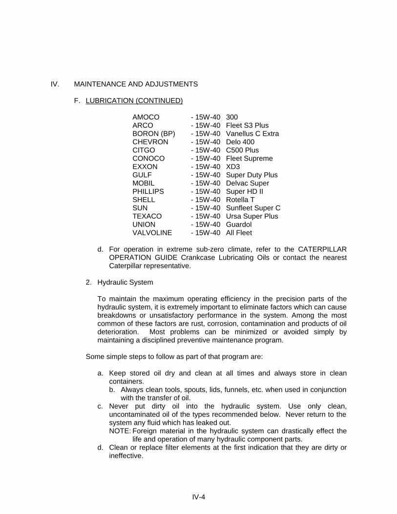
c. New engines are shipped with ASHLAND 400M + HDT 15W-40 but the following multi-grade crankcase oils are recommended for use or replacement in normal operation (10 deg. F to 90 deg. F) (-12 deg. C to 32 deg. C).
IV-3
IV. MAINTENANCE AND ADJUSTMENTS F. LUBRICATION (CONTINUED)
AMOCO - 15W-40 300 ARCO - 15W-40 Fleet S3 Plus BORON (BP) - 15W-40 Vanellus C Extra CHEVRON - 15W-40 Delo 400 CITGO - 15W-40 C500 Plus CONOCO - 15W-40 Fleet Supreme EXXON - 15W-40 XD3 GULF - 15W-40 Super Duty Plus MOBIL - 15W-40 Delvac Super PHILLIPS - 15W-40 Super HD II SHELL - 15W-40 Rotella T SUN - 15W-40 Sunfleet Super C TEXACO - 15W-40 Ursa Super Plus UNION - 15W-40 Guardol VALVOLINE - 15W-40 All Fleet
d. For operation in extreme sub-zero climate, refer to the CATERPILLAR
OPERATION GUIDE Crankcase Lubricating Oils or contact the nearest Caterpillar representative.
2. Hydraulic System
To maintain the maximum operating efficiency in the precision parts of the hydraulic system, it is extremely important to eliminate factors which can cause breakdowns or unsatisfactory performance in the system. Among the most common of these factors are rust, corrosion, contamination and products of oil deterioration. Most problems can be minimized or avoided simply by maintaining a disciplined preventive maintenance program.
Some simple steps to follow as part of that program are:
a. Keep stored oil dry and clean at all times and always store in clean
containers. b. Always clean tools, spouts, lids, funnels, etc. when used in conjunction
with the transfer of oil. c. Never put dirty oil into the hydraulic system. Use only clean,
uncontaminated oil of the types recommended below. Never return to the system any fluid which has leaked out. NOTE: Foreign material in the hydraulic system can drastically effect the
life and operation of many hydraulic component parts. d. Clean or replace filter elements at the first indication that they are dirty or
ineffective.
IV-4

IV. MAINTENANCE AND ADJUSTMENTS F. LUBRICATION (CONTINUED)
Mixing of different manufacturers' hydraulic fluid is not recommended. However, it can be done if the fluids are miscible (contain the same base and additive). It may be necessary to contact an oil supplier to determine this.
New power units are shipped with CHEVRON Clarity AW46 hydraulic oil. The following recommended fluids may be used when replacing fluid in the hydraulic system.
FIRST Preference Group:
CHEVRON Clairity AW46 MOBIL DTE-15 SUN 2105
SECOND Preference Group:
ARCO Duro AW46 CHEVRON Hydraulic AW46 PHILLIPS Magnus A46 SHELL Tellus 46
THIRD Preference Group:
BORON Energol HLP46 CITGO A.W. Hydraulic 46 CONOCO Super 46 EXXON Nuto H46 GULF Harmony 46AW SUN Sunvis 846 TEXACO Rando HD AZ46 UNION Unax AW46
Whenever fluids from the second preference group are used, it is necessary to test the oil more often to insure that viscosity remains within recommended limits while in service. Using fluids from the third preference group requires even a more discerning inspection than use of fluids from the second group.
The recommended fluids were chosen based on the hydraulic system operating temperature range being 5 deg. F (-15 deg. C) (cold [ambient[ start-up to 160 deg. F (71 deg. C) (maximum operating).
IV-5
IV. MAINTENANCE AND ADJUSTMENTS F. LUBRICATION (CONTINUED)
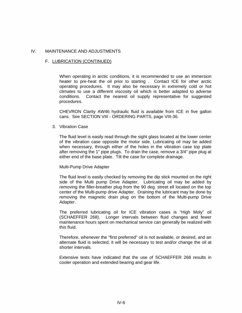
When operating in arctic conditions, it is recommended to use an immersion heater to pre-heat the oil prior to starting . Contact ICE for other arctic operating procedures. It may also be necessary in extremely cold or hot climates to use a different viscosity oil which is better adapted to adverse conditions. Contact the nearest oil supply representative for suggested procedures.
CHEVRON Clarity AW46 hydraulic fluid is available from ICE in five gallon cans. See SECTION VIII - ORDERING PARTS, page VIII-36.
3. Vibration Case
The fluid level is easily read through the sight glass located at the lower center of the vibration case opposite the motor side. Lubricating oil may be added when necessary, through either of the holes in the vibration case top plate after removing the 1" pipe plugs. To drain the case, remove a 3/4" pipe plug at either end of the base plate. Tilt the case for complete drainage.
Multi-Pump Drive Adapter
The fluid level is easily checked by removing the dip stick mounted on the right side of the Multi pump Drive Adapter. Lubricating oil may be added by removing the filler-breather plug from the 90 deg. street ell located on the top center of the Multi-pump drive Adapter. Draining the lubricant may be done by removing the magnetic drain plug on the bottom of the Multi-pump Drive Adapter.
The preferred lubricating oil for ICE vibration cases is “High Moly" oil (SCHAEFFER 268). Longer intervals between fluid changes and fewer maintenance hours spent on mechanical service can generally be realized with this fluid.
Therefore, whenever the "first preferred" oil is not available, or desired, and an alternate fluid is selected, it will be necessary to test and/or change the oil at shorter intervals.
Extensive tests have indicated that the use of SCHAEFFER 268 results in cooler operation and extended bearing and gear life.
IV-6
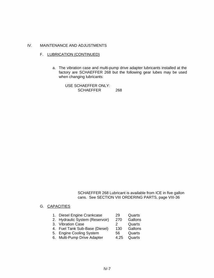
IV. MAINTENANCE AND ADJUSTMENTS F. LUBRICATION (CONTINUED)
a. The vibration case and multi-pump drive adapter lubricants installed at the factory are SCHAEFFER 268 but the following gear lubes may be used when changing lubricants:
USE SCHAEFFER ONLY:
SCHAEFFER 268
SCHAEFFER 268 Lubricant is available from ICE in five gallon cans. See SECTION VIII ORDERING PARTS, page VIII-36
G. CAPACITIES
1. Diesel Engine Crankcase 29 Quarts 2. Hydraulic System (Reservoir) 270 Gallons 3. Vibration Case 2 Quarts 4. Fuel Tank Sub-Base (Diesel) 130 Gallons 5. Engine Cooling System 56 Quarts 6. Multi-Pump Drive Adapter 4.25 Quarts
IV-7
IV. MAINTENANCE AND ADJUSTMENTS H. DRAINING AND FILLING HYDRAULIC FLUID RESERVOIR
1. The Hydraulic reservoir is draining by removing a plug on the bottom of the reservoir.
2. The hydraulic reservoir is filled by the manual pump mounted on the back
(engine side) of the reservoir. All fluid is pumped to the reservoir through the returned filter (F2) to insure no dirt enters the hydraulic system.
I. CHANGING HYDRAULIC RETURN FILTER ELEMENTS
1. The return filters are located on the hydraulic reservoir above the hex key rack.
2. To remove the return filter elements, you must use a filter wrench capable of
excepting a 5" diameter filter. (Available at your local auto-parts store.) Unscrew the return filter elements counterclockwise to remove. Remove both filter elements and gaskets from the filter housing.
3. Clean filter housing with a lint free rag.
4. Install the new gaskets to the new filter elements. Apply a light coating of
multi-purpose grease to the top of each gasket.
5. Screw the return filter elements and gaskets clockwise onto the filter housing until the gaskets make contact to the filter housing base.
6. Using the filter wrench, tighten both return filter elements approximately 3/4 of
a turn.
7. With four new return filter elements installed, start the power unit and run for approximately three minutes. CHECK FOR LEAKS.
IV-8
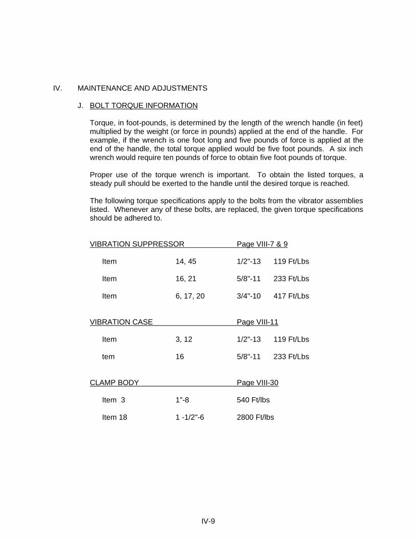
IV. MAINTENANCE AND ADJUSTMENTS J. BOLT TORQUE INFORMATION
Torque, in foot-pounds, is determined by the length of the wrench handle (in feet) multiplied by the weight (or force in pounds) applied at the end of the handle. For example, if the wrench is one foot long and five pounds of force is applied at the end of the handle, the total torque applied would be five foot pounds. A six inch wrench would require ten pounds of force to obtain five foot pounds of torque.
Proper use of the torque wrench is important. To obtain the listed torques, a steady pull should be exerted to the handle until the desired torque is reached.
The following torque specifications apply to the bolts from the vibrator assemblies listed. Whenever any of these bolts, are replaced, the given torque specifications should be adhered to.
VIBRATION SUPPRESSOR Page VIII-7 & 9
Item 14, 45 1/2"-13 119 Ft/Lbs
Item 16, 21 5/8"-11 233 Ft/Lbs
Item 6, 17, 20 3/4"-10 417 Ft/Lbs
VIBRATION CASE Page VIII-11
Item 3, 12 1/2"-13 119 Ft/Lbs
tem 16 5/8"-11 233 Ft/Lbs
CLAMP BODY Page VIII-30
Item 3 1"-8 540 Ft/lbs
Item 18 1 -1/2"-6 2800 Ft/lbs
IV-9

V. HYDRAULIC CIRCUITRY (REFERENCE:HYDRAULIC SCHEMATIC PG V-4) A. HYDRAULIC CLAMP
With the diesel engine running, hydraulic fluid is taken from the reservoir by the clamp pump (P2). The clamp pump flow returns to the reservoir if the clamp switch on the pendant has not been moved.
Turning the clamp switch on the control pendant to CLOSE activates the CLAMP CONTROL VALVE (V1). Hydraulic fluid is directed to the CLOSE CLAMP side of the hydraulic CYLINDER (CYL) in the hydraulic clamp. The clamp closes. Clamping pressure is indicated by the clamp pressure gage (GA-3). When clamping pressure reaches approximately 4200 PSI, the CLAMP PRESSURE SWITCH (PS-1) deactivates the CLAMP CONTROL VALVE (V1), which directs the flow from the clamp pump to the reservoir. Pressure at the clamp is maintained by the CLAMP CHECK VALVE (CV5). If clamping pressure falls below 3900 PSI, the CLAMP PRESSURE SWITCH activates the CLAMP CONTROL VALVE to restore pressure. In the event of hose failure, a second CLAMP CHECK VALVE (CV7), located in the CLAMP CYLINDER, will hold the CLAMP CYLINDER closed.
Turning the clamp switch on the control pendant to OPEN activates the CLAMP CONTROL VALVE (V1). Hydraulic fluid is directed to the OPEN CLAMP side of the hydraulic cylinder. The pressure in the OPEN CLAMP line opens the CLAMP CHECK VALVE (CV5). The clamp opens. Pressure in the OPEN CLAMP line is indicated by the clamp pressure gage (GA-4).
Pressure in the clamping circuit is limited to 4500 PSI by the clamp relief valve (RV2). The quick-disconnect couplers (QD3 & QD4) permit de-coupling of the clamp hoses at the power unit.
NOTE: Clamp pump flow may also be used to power some auxilary functions.
Contact ICE for information on “Power Beyond” modifications. B. VIBRATOR DRIVE
With the diesel engine running, hydraulic fluid is taken from the reservoir by two DRIVE PUMPS (P1) and directed to the CONTROL MANIFOLD. Fluid pressure opens the cartridges (CA1 and CB1), which vent the hydraulic fluid back to the reservoir through the RETURN FILTER (F2), if the vibrator switch on the pendant has not been moved.
V-1
V. HYDRAULIC CIRCUITRY B. VIBRATOR DRIVE (CONTINUED)
Turning the vibrator switch, on the control pendant, to FORWARD activates the FORWARD SOLENOID on the CONTROL VALVE (V2). By blocking the pilot flow from cartridge (CB1 and CA2), the CONTROL VALVE (V2) causes these cartridges to close, thus directing pump flow to the VIBRATOR MOTOR (M).
Full motor speed is reached within a few seconds and the motor drive pressure is indicated by GAGE (GA - 1). Maximum drive pressure is limited to approximately 5000 PSI by the FORWARD RELIEF VALVE (RV1). The FORWARD RELIEF VALVE (RV1), if opened by over pressure, permits a small pilot flow from cartridges (CB1 AND CA2). This pilot flow causes cartridges (CB1 and CA2) to partially open and allows some or all of the pump flow to return to the reservoir. Case drain fluid from the motors returns to the reservoir. Case drain pressure is limited to 50 PSI by the case drain RELIEF VALVE (RV3). Oil returning from the VIBRATOR MOTORS (M) opens cartridge CB2 and returns to the reservoir through COOLER VALVE (V3) and FILTER (F2). A small amount of fluid is diverted from the return line, by the FLOW CONTROL (FC), through the VIBRATOR MOTOR (M) to provide additional motor cooling.
Returning the Vibrator Switch to the center position de-energizes control valve (V2), and again opens cartridges CA1 and CB1 which allows pump flow to return to the reservoir without driving the vibrator. In neutral, CONTROL VALVE, (V2) also blocks pilot flow from cartridges (CA2) and the oil returning from VIBRATOR MOTORS (M). To produce a "Braking" Action. When return oil pressure reaches 1000 PSI, REVERSE RELIEF VALVE (RV4) permits a small pilot flow from cartridge (CB2). This pilot flow allows cartridge (CB2) to partially open and direct motor return flow to the reservoir at 1000 PSI. Cavitation of the VIBRATOR MOTORS (M) is prevented during braking, by CHECK VALVE (CV-6). The vibrator switch may be momentairly turned to REVERSE for quicker stopping of the motor.
Hydraulic fluid temperature is regulated by the COOLER VALVE (V3). When fluid temperature is below 100 deg. F, V3 directs the flow directly to the reservoir through FILTER (F2). When fluid temperature exceeds 100 deg. F, COOLER VALVE (V3) directs flow through the HEAT EXCHANGER (HE) before it enters the reservoir, through FILTER (F2). Excessive pressure in the HEAT EXCHANGER (HE) is prevented by CHECK VALVE (CV-2), which bypassed excess flow and limits pressure to 65 PSI.
The quick-disconnect couplers (QD1, QD2, and QD5) permit de-coupling of the drive and case drain hoses at the power unit.
V-2
V. HYDRAULIC CIRCUITRY C. AUGER DRIVE
To convert the 325 Power Unit to operate an ICE, or similar, Bi-Directional Drill open (CCW) VIBRO-AUGER valve (V4) fully. Re-adjust RELIEF VALVES (RV-1 & RV4) to forward & reverse pressure specified for Auger, and re-set RELIEF VALVE (RV-2), if necessary, for two speed signal.
See ICE Auger Manuals for description of Hydraulic Control Manifold operation, in the "Auger Mode."
D. HYDRAULIC IMPACT HAMMER
To convert a 325 Power Unit to operate an ICE Hydraulic Impact Hammer, open (CCW) VIBRO-AUGER valve (V4) fully. Readjust RELIEF VALVE (RV1) to specified pressure, and reset RELIEF VALVE (RV2) for two stroke signal.
See ICE Hydraulic Impact Hammer Mannual for complete Impact Hammer set up instructions.
E. OTHER
Returning fluid is filtered by the RETURN FILTER (F2). INDICATOR GAGE (GA5) shows condition of FILTER (F2).
A manual PUMP (MP) is provided to fill the hydraulic reservoir. A CHECK VALVE (CV4) prevents loss of fluid from the reservoir back through this pump.
A TEMPERATURE SWITCH (TS) located in the reservoir operates the hydraulic fluid cold light.
The HEAT EXCHANGER (HE) cools the hydraulic fluid returning to the reservoir.
Motor cavitation is prevented in the braking operation by the CHECK VALVE (CV6).
Extra Long ACCUMULATOR HOSE (AC) in pilot system expands as pressure increases. The additional pilot flow causes (CA2) to produce a smooth acceleration of VIBRATOR MOTOR (M).
V-3

V. HYDRAULIC CIRCUITRY HYDRAULIC SCHEMATIC
V-4
25MIC
25MIC
GA-5 GA-5
25MIC
25MIC
F2 F2
P2
P1
P1 MU
LTI-P
UM
P D
RIV
E
ENGINE3306DITA
1400-2200 RPM
H.E.CV-4
MP
0CA B
P T
4500
RV-2
V1
CV-5
PS-1
4200
GA-3 GA-4
QD-4 QD-3
3/8" _ 3/8" _
GA-1FORWARD
5000
RV-1
1/1
CV-2
65
CB-1
2
1/1CB-2
2
RV-4
1000V3CC3 CC4
2/1
2
CA-1 CA-2 2/1
2
V2
FOR REV
CC1
GA-2REVERSE
V4AUG
VIB
M
CV-6
65
1 1/4" _
QD2 / FORWARD
VIBRATOR
50 PSIRV-3
QD
-5
3/4"
_
CONTROL MANIFOLD
TS
RESEVOIR
QD1 / REVERSE
1 1/2" _
CC2
AC-400"
CLAMP CYLINDERCV-7
FC

V. HYDRAULIC CIRCUITRY F. HYDRAULIC COMPONENTS LIST Part Page Notation Description Number Ref.__ AC Accumulator Hose 110680 VIIV-25 CA1 & 2 Cartridge A (2) 110624 VIII-27 CB1 & 2 Cartridge B (2) 110622 VIII-27 CC1 Cartridge Cover 110530 VIII-27 CC2 Cartridge Cover 110606 VIII-27 CC3 Cartridge Cover 110546 VIII-27 CC4 Cartridge Cover 110544 VIII-27 CV2 Check Valve 130339 VIII-27 CV4 Manual Pump Check Valve 100451 VIII-19 CV5 Clamp Check Valve 110149 VIII-29 CV6 Check Valve - Vibrator 810435 VIII-7 CV7 Check Valve - Clamp Cylinder 120629 VIII-31 E Diesel Engine 100508 VIII-17 F2 Return Filter 100518 VIII-17 FC Flow Control 810667 VIII-10 GA-1 Forward Pressure Gage 110600 VIII-25 GA-2 Reverse Pressure Gage 110600 VIII-25 GA-3 Close Clamp Pressure Gage 110600 VIII-25 GA-4 Open Clamp Pressure Gage 110600 VIII-25 GA-5 Filter Indicator Gage 100436 VIII-21 HE Heat Exchange 400099 VIII-17 M Motor 130493 VIII-11 MP Manual Pump 100447 VIII-19 P1 Drive Pumps (2) 100510 VIII-17 P2 Clamp Pump 100684 VIII-17 PS-1 Clamp Pressure Switch 100627 VIII-29 QD1 Vibrator Reverse Disconnect 110690 VIII-17 QD2 Vibrator Forward Disconnect 110692 VIII-17 QD3 Clamp Open Disconnect 100777 VIII-20 QD4 Clamp Close Disconnect 100245 VIII-20 QD5 Case Drain Disconnect 400095 VIII-17 RV1 Forward Relief Valve 100632 VIII-27 RV2 Clamp Relief Valve 100898 VIII-29 RV3 Case Drain Relief Valve 100032 VIII-7 RV4 Reverse Relief Valve 100630 VIII-27 TS Temperature Switch 400115 VIII-20 VI Clamp Control Valve 110147 VIII-29 V2 Control Valve 810519 VIII-27 V3 Cooler Valve 110628 VIII-27 V4 Vibro-Auger Valve 100654 VIII-27
V-5

VI. ELECTRIC CIRCUITRY (REFERENCE:ELECTRICAL SCHEMATIC PG VI-3) A. DIESEL ENGINE
The BATTERIES provides 24-volt current to start the diesel engine. In order to start the diesel engine, the circuit breaker (MAIN POWER) switch should be ON and the vibrator switch on the remote control pendant should be in the neutral position. This insures that the vibrator will not begin vibrating when the engine starts. Turning the ENGINE START SWITCH to START energizes the START RELAY which energizes the START MOTOR and turns over the diesel engine. If fuel is available, the diesel engine will start. In order for fuel to be available to the engine, the shutdown reset must be closed (pushed in) to energize the FUEL SOLENOID. The FUEL SOLENOID opens the injector pump and allow fuel to flow to the engine. With the diesel engine running, the AMMETER indicates charging amperes. The HOUR METER indicates engine operating hours. A TACHOMETER (TACH) indicates engine speed.
A system of safety controls shut off the fuel supply, which stops the diesel engine in the event that engine water temperature is too high or engine oil pressure is too low. The heart of the safety system is the shutdown reset, which is normally closed, thereby providing current to operate the HOUR METER and to energize the FUEL SOLENOID. Energizing the fuel solenoid opens the injector pump and allows fuel to flow to the diesel engine. The shutdown reset must remain closed so that fuel continues to flow to the diesel engine.
If the coil in the shutdown reset is energized, the shutdown reset will open, shutting off the fuel to the diesel engine. The engine will stop. The coil may be energized by either of the following devices:
1. ENGINE OIL PRESSURE GAGE - If oil pressure is below 15 PSI, contacts in
the gage will be closed providing current to energize the shutdown reset coil. On start-up, the reset button of the shutdown reset (on the control panel) must be held in until oil pressure exceeds 30 PSI.
2. ENGINE WATER TEMPERATURE GAGE - If water temperature exceeds
210 deg. F, the contacts of the gage will close energizing the shutdown reset coil.
3. Pushing the EMERGENCY STOP BUTTON on Remote Control Pendent
energizes the shutdown reset coil.
The diesel engine is stopped by turning the ENGINE START SWITCH to OFF. This will de-energize the FUEL SOLENOID shutting off the fuel to the engine.
VI-1
VI. ELECTRICAL CIRCUITRY B. HYDRAULIC CLAMP
With the diesel engine running, turning the clamp switch (OPEN-CLOSE), on the control pendant to CLOSE energizes the close-clamp solenoid (CLOSE-SOL.). This operates the clamp control hydraulic valve and closes the clamp.
When the pressure in the close-clamp hydraulic circuit reaches 4200 PSI, the pressure switch (PS-1) opens and de-energizes the close-clamp solenoid and turns on the CLAMP LIGHTS on the control pendant and control panel. If close-clamp pressure falls below 3900 PSI, the pressure switch closes and re-energizes the close-clamp solenoid to rebuild pressure. The CLAMP LIGHTS go out. When pressure returns to 4200 PSI, The pressure switch opens de-energizing the close-clamp solenoid and turns on the CLAMP LIGHTS.
With the diesel engine running, turning the clamp switch (OPEN-CLOSE) to OPEN energizes the open-clamp solenoid (OPEN SOL.). The clamp opens.
C. VIBRATOR
With the diesel engine running, turning the vibrator switch on the control pendant to the FORWARD position energizes the forward SOLENOID on the control valve(V2). The control valve directs hydraulic fluid to the hydraulic motors and the vibrator starts.
With the diesel engine running, turning the vibrator switch on the control pendant to the center position de-energizes the forward SOLENOID. Fluid no longer is directed to the motor and they stop.
D. OTHER
With the MAIN POWER switch ON, the TEMPERATURE SWITCH turns on the HYDRAULIC FLUID COLD LIGHT if the temperature of the hydraulic fluid in the reservoir is below 60 deg. F. At 60 deg. F or above, the TEMPERATURE SWITCH turns off the HYDRAULIC FLUID COLD LIGHT.
Duplicate vibrator and clamp switches are located on the control pendant and on the control panel. Turning the LOCAL-REMOTE switch to LOCAL activates only the clamp and vibrator switches located on the control panel. Turning the LOCAL-REMOTE switch to REMOTE only permits operation of the clamp and vibrator from the control pendant.
VI-2
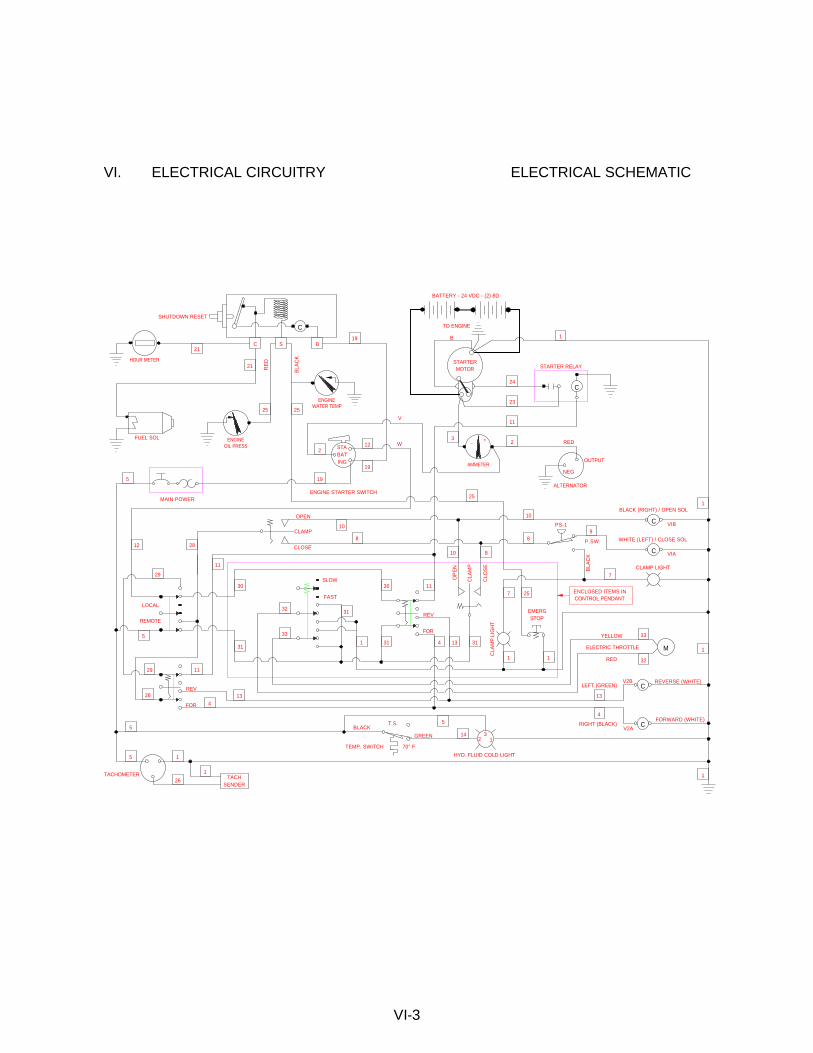
VI. ELECTRICAL CIRCUITRY ELECTRICAL SCHEMATIC
VI-3
STARTERMOTOR
TO ENGINE
BATTERY - 24 VDC - (2) 8D
1
24
23
STARTER RELAY
11
2+-3RED
AMMETER
ALTERNATOR
NEG
OUTPUT
C
BATSTA
ING
12
19
2
19
V
W
ENGINE STARTER SWITCHMAIN POWER
5
ENGINEWATER TEMP
S BC
C
19
25
BLA
CK
RE
D
25
OIL PRESSENGINE
HOUR METER
FUEL SOL
21
21
SHUTDOWN RESET
25
10
8
10
8CLAMP
OPEN
CLOSE28
11
C
BLACK (RIGHT) / OPEN SOL
PS-1
C
WHITE (LEFT) / CLOSE SOL
CLAMP LIGHT
VIB
VIA
BLA
CK
P.SW.
9
7
REV
FOR
31
3030 11SLOW
FAST
1
31
33
32
31
12
5
LOCAL
REMOTE
29
REV
FOR
1129
28
134
134
TACHSENDER
5
26
1
5
TACHOMETER
CLA
MP
CLO
SE
OP
EN
810
31
CLA
MP
LIG
HT
1
7 25
1
EMERGSTOP
ENCLOSED ITEMS INCONTROL PENDANT
V2BC
M
33
32
YELLOW
RED
ELECTRIC THROTTLE
V2AC
1
REVERSE (WHITE)
FORWARD (WHITE)
LEFT (GREEN)
RIGHT (BLACK)
23
1
T.S.BLACK
TEMP. SWITCH
GREEN 14
5
HYD. FLUID COLD LIGHT
1
1
4
13
1
B
70° F

VI. ELECTRICAL CIRCUITRY E. ELECTRICAL COMPONENTS LIST Part Page Notation Reference Number Ref. ALTERNATOR Alternator See Cat. Parts Book AMMETER Ammeter 110371 VIII-23 BATTERY 24-Volt Battery 400890 VIII-17 CLAMP LIGHT (2) Clamp Light 100359 VIII-25 ENG. START SW. Engine Start Switch 130259 VIII-25 FOR/REV (2) Vibrator Switch (FWD/REV) 130155 VIII-25 FUEL SOL. Fuel Solenoid Valve See Cat. Parts Book HOUR METER Hour Meter 100343 VIII-23 HYD. FLUID COLD Hyd.Fluid Warning Light 100355 VIII-23 LOCAL-REMOTE Local-Remote Switch 140361 VIII-25 MAIN POWER Main Power Circuit Breaker 400141 VIII-23 OIL PRESSURE Oil Pressure Gage 100329 VIII-23 OPEN/CLOSE (2) Clamp Switch (OPEN/CLOSE) 130155 VIII-23 PS-1 Pressure Switch 100627 VIII-29 STARTER MOTOR Engine Starter See Cat.Parts Book START RELAY Engine Start Relay Switch See Cat.Parts Book SHUTDOWN RESET Shutdown Reset 130257 VIII-25 TACH Tachometer See Cat.Parts Book TACH SENDER Tachometer Sender See Cat.Parts Book TEMP. SWITCH Temperature Switch 400115 VIII-20 V1A Close-Clamp Solenoid (Valve) 110147 VIII-29 V1B Open-Clamp Solenoid (Valve) 110147 VIII-29 V2A Forward Solenoid (Valve) 810519 VIII-27 V2B Reverse Solenoid (Valve) 810519 VIII-27 WATER TEMP. Water Temperature Gage 130251 VIII-23 EMERGENCY STOP Emergency Stop Button 130507 VIII-25 SLOW-FAST Engine Throttle Switch 130509 VIII-25
VI-4
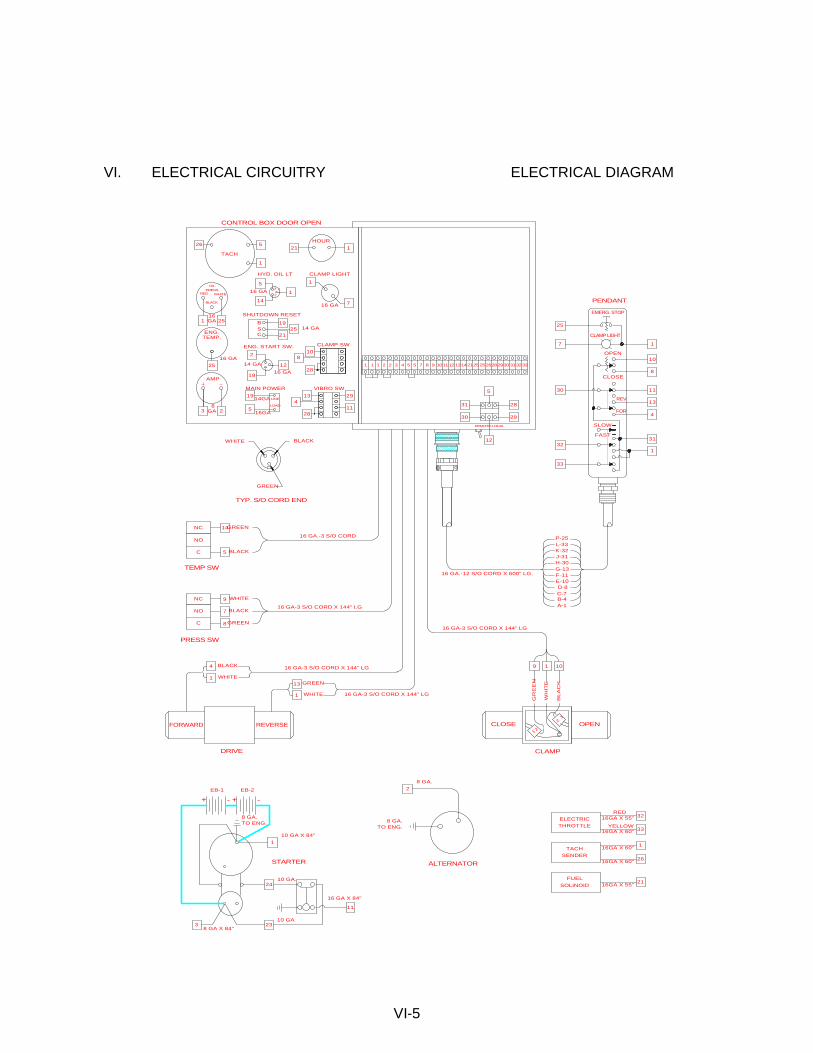
VI. ELECTRICAL CIRCUITRY ELECTRICAL DIAGRAM
VI-5
BLACK
GREEN
TYP. S/O CORD END
WHITE
P-25
K-32J-31H-30G-13F-11E-10D-8
L-33
C-7B-4A-1
CLOSE OPEN1 2
21
GR
EE
N
WH
ITE
BL
AC
K
WHITE
BLACK
GREEN
NC
NO
C
PRESS SW
FORWARD
BLACK
WHITE
8 GA.
8 GA.TO ENG.
STARTER
10 GA.
10 GA
ALTERNATOR
8 GA.TO ENG.
RED
YELLOW
16 GA-3 S/O CORD X 144" LG
16 GA-3 S/O CORD X 144" LG
16 GA-3 S/O CORD X 144" LG
PENDANT
OILPRESS.
RED
BLACK
WHITE
LINE
LOAD
16GA
8 GA
16 GA1
REMOTE-LOCAL
CLAMP
25
7 1
10
8
11
13
4
30
31
1
33
32
FAST
SLOW
FOR
REV
CLOSE
OPEN
CLAMP LIGHT
EMERG. STOP
23
2
24
110 GA X 84"
38 GA X 84"
EB-1 EB-2
11
16 GA X 84"
+ - -+
21
32
33
1
26
FUELSOLINOID
THROTTLEELECTRIC
SENDERTACH
16GA X 60"
16GA X 55"
16GA X 60"
16GA X 60"
1019
VIBRO SW
29
1128
413
MAIN POWER
19
5
121HOUR
26 5
1
3 2
25
1 25
AMP
ENG.TEMP.
TACH
810
28
CLAMP SW
2
19
1216 GA
14 GA
ENG. START SW.
2519
21CSB
1
14
HYD. OIL LT
16 GA
513
2
SHUTDOWN RESET
16GA
14GA
1
716 GA
CLAMP LIGHT
12
30
31
5
28
29
1 1 2 2 3 4 5 75 8 9 101112 13 2114 25 2628 313029 3233
16GA X 55"
16 GA.-12 S/O CORD X 600" LG.
REVERSE
16 GA-3 S/O CORD X 144" LG
DRIVE
1
4
8
7
9
WHITE
GREEN13
1
TEMP SW
C
NO
NC
BLACK5
GREEN
14
16 GA.-3 S/O CORD
25
14 GA
CONTROL BOX DOOR OPEN

VII. GENERAL DATA A. ABBREVIATIONS
The abbreviations shown below are used throughout the parts lists and various other parts of the manual.
ASM. Assembly BHCS Button Head Cap Screw Cyl. Cylinder DC Direct Current FHCS Flat Head Cap Screw FLCS Flanged Head Cap Screw HC High Collar HHCS Hex Head Cap Screw HHPP Hex Head Pipe Plug HSSS Hex Socket Set Screw Hyd. Hydraulic Lg. Long mm Millimeter Mtg. Mounting NPT. National Pipe Thread PHMS Phillips Head Machine Screw P/N Part Number Qty. Quantity RHMS Round Head Machine Screw Sch. Schedule SHCS Socket Head Cap Screw SHPP Socket Head Pipe Plug SHSS Socket Head Shoulder Screw S/N Serial Number Sol. Solenoid
B. SCREWS AND BOLTS
1. Practically all connections on the unit are made with socket head (Allen) cap screws. These high-strength screws are available at most industrial supply houses.
2. Screws and bolts are designated in the PARTS LIST in abbreviated form. (Refer to sub-section A, above, for specific abbreviations.) Listed below is a typical screw description: .5 - 13 UNC x 1.50 LG SHCS .5 = Diameter
13 UNC = Threads Per Inch 1.50 LG = Length SHCS = Screw Type Abbreviation
3. Some screws or bolts require a specific torque when replacing. For
identification of these bolts and a more thorough understanding of torque, refer to page VIII-42.
VII-1

VII. GENERAL DATA C. SERIAL NUMBER LOCATIONS
1. The following ICE vibratory units are serial numbered separately:
a. Vibrator b. Power unit c. Piling Clamps d. Caisson beams e. 90 deg. clamp adapter
2. In addition to the serial number plate itself (on vibrators, power units and
clamps), the serial number is stamped into each unit in one or more places as follows:
a. Vibrator stamped twice - once on top right side of suppressor housing,
once on bottom lip of vibration case on right side of motors' side.
b. Power unit stamped twice - once on control panel side of unit at right corner of reservoir, once on sub-base inside door below hex-key rack.
c. Model 126B universal clamp is stamped three times - once between
cylinder and pile guide, once above the grease fitting, and once on the flange of the cylinder housing.
d. Model 127 Z-Pile clamp stamped twice- once in front of cylinder guard,
once in back opening of pile guide.
e. Model 80 caisson clamp stamped twice - once by the lifting eye, once by the adjusting screw.
f. Caisson beams is stamped three times- once on top center, once in center
of both sides of flange.
g. 90 deg. clamp plate stamped twice - once on top center, once on side.
VII-2
VIII. ORDERING PARTS A. PROCEDURE
1. When ordering parts, be sure to include the model and serial number of the unit or component. The serial number may be located by referring to SECTION VII, SERIAL NUMBER LOCATION. Confirm all telephone orders immediately to avoid duplicating shipment.
2. ORIGINAL EQUIPMENT; Where component serial numbers are given, these
apply only to equipment and components originally furnished with the unit. Where equipment has been changed or upgraded these numbers may not be an adequate description.
3. SHIPMENT; State to whom shipment is to be made and method of shipment
desired, otherwise our own judgement will be used.
4. SHORTAGES; Claims for shortages or errors should be made immediately upon receipt of parts. No responsibility will be assumed for delay, damage or loss of material while in transit. Broken, damaged or lost material should be refused or a full description made of damage or loss to the carrier agent on the freight or express bill.
5. RETURN OF PARTS; If for any reason you desire to return parts to the
factory or to any distributor from whom these parts were obtained, you must first secure permission to return the parts. Shipping instructions will be given along with this permission. A ten percent handling charge must be assessed against the returned shipment unless an error is made by the factory or by the distributor when filling your order.
VIII-1

VIII. ORDERING PARTS B. FITTING DESCRIPTION KEY
VIII-2
SELECTOR INDEX 2 - INCH FITTING
9 - METRIC FITTING
CONFIGURATION OR SHAPE OF FITTING S - STRAIGHT FITTING
L - 90 Deg. ELBOW
V - 45 Deg. ELBOW T - TEE
C - CAP
P - PLUG
U - UNION
X - CROSS
FITT
(FOURTH END FITT'G REQ'D.)
FIRST END SIZE * IN 1/16THS OF AN INCH
(INDEX 2)
IN MILLIMETERS (INDEX 9)
SEE GENERAL SPECIFICATION
SHEET FOR SEQUENCE OF ORDER
FIRST END FITTING STYLE SEE FITTING STYLE SELECTOR
CHART SC-1
SECOND END SIZE IF APPLICIABLE - SEE
FIRST END SIZE
SECOND END FITTING STYLE IF APPLICABLE - SEE
FIRST END FITTING STYLE
THIRD END SIZE IF APPLICABLE - SEE
FIRST END SIZE
THIRD END FITTING STYLE
FIRST END SIZE
IF APPLICABLE - SEE
* EXCEPTIONS 90 = 10"
92 = 12"
94 = 14"
MATERIAL 1 - CARBON STEEL
2 - BRASS
4 - STAINLESS STL
5 - AAR MAL IRON 6 - MALEABLE IRON
8 - FORGED STEEL
SPECIAL NOTATIONS
0 - NONE 1 - 125 LB.
3 - SCH 40
4 - SCH 80
PRESSURE RATING
INSTALLATION AID OR STYLE OF HEAD 0 - NOT APPLICABLE H - REGULAR HEX
Q - SQUARE HEAD (EXT.)
R - SQUARE HEAD (INT.) S - HEX HEAD (INT SOCKET)
T - HEX HEAD (EXT.)
LENGTH CODE (ELBOWS & NIPPLES)
__L - LONG (ELBOW)
__X - EXTRA LONG (ELBOW)
__C - CLOSE (NIPPLE)
(CROSSES ONLY)
PIPE NIPPLES (LONG) ONLYIN DEC. INCHES FOR INDEX 2
050 = 5.0 INCHES
105 = 10.5 INCHES
99 = NON CODE SIZE
98 = 8"
96 = 6"
SEE FIRST END FITTING SIZE OR
END STYLE
IN MILLIMETERS FOR INDEX 9
120 = 12.0 MILLIMETERS084 = 8.4 MILLIMETERS
FOURTH END SIZE &FITTING STYLE
2 L 16 M 12 J 00 0 00L 0 0 0 1- -

VIII. ORDERING PARTS B. FITTING DESCRIPTION KEY (CONTINUED)
FITTING STYLE SELECTOR CHART
SC-1
FOR END FITTING STYLE SELECTION
VIII-3
M
P
R
B
D
S
J
Q
K
N
H
F
JIC MALE
37 Deg. FLARE
MALE PIPE
NPT
S.A.E. MALE0-RING
(& ADJUSTABLE)
JIC MALE37 Deg. FLARE
BULKHEAD
MALE PIPE
NPT SWIVEL
B.S.P. MALE
PIPE
JIC FEMALE37 Deg. FLARE
(& SWIVEL)
FEMALE PIPENPTF
S.A.E. FEMALE
O-RING
FEMALE PIPE
NPSM-SWIVEL
SPLIT FLANGE3000 PSI.CODE 61
SPLIT FLANGE6000 PSI.CODE 62

VIII. ORDERING PARTS C. HOSE DESCRIPTION CODE
The HOSE DESCRIPTION CODE is a 24 digit number enabling easier and quicker identification whenever a hose replacement is desired. The key below explains the structure of the coded number in detail.
HOSE 125 R11 F 9 24 P 0 20 L0395 S
HOSE I.D. IN INCHES 2 PLACE DECIMAL SPECIAL CODE (125=1-1/4”) (050=1/2”) etc. O=None S=Spring Gaurd L=S.S. Braid SAE OR MANUFACTURER D=Offset RATING (or Special Code) (PT4=Power Track) (AQ1=Aeroquip H-Pac) (TF1=Teflon) (R01=SAE Rating 100R1) etc. LENGTH IN INCHES (1 PLACE DECIMAL) (0395=39-1/2”) FIRST END-TYPE OF FITTING (1242=124-1/4”) (F=3000 lb Flange) (P=Male Pipe) etc. (H=6000 lb Flange) (M=37° Male JIC) (J=JIC Swivel 37°) FIRST END-BEND ANGLE (0=None) (9=90°) (3=30°) etc. FIRST END-SIZE IN 1/16 ths SECOND END-TYPE OF FITTING (See codes for FIRST END) SECOND END-BEND ANGLE (See codes for FIRST END) SECOND END-SIZE IN 1/16 ths
VIII-4
VIII. ORDERING PARTS D. PARTS IDENTIFICATION
1. Parts lists and drawings are included on the following pages for the equipment components shown below:
a. VIBRATION SUPPRESSOR 800381 b. VIBRATION CASE 810583 c. HOSE ASSEMBLIES -INTERCONNECTING 800029 d. POWER UNIT - ENCLOSURE 800379 e. POWER UNIT - INTERNAL 800377 f. CONTROL BOX 810585 g. CONTROL MANIFOLD ASSEMBLY 810571 h. CLAMP MANIFOLD 810449 i. MODEL 126B CLAMP 800327 j. MODEL 127 Z-PILE CLAMP 800041 l. CLAMP EXTENSION - 10 FOOT 800423 m. 90 deg. CLAMP ADAPTER 800049
2. The spare parts list SECTION VIII - RECOMMENDED SPARE PARTS
contains spare parts which may be very useful in keeping down-time to a minimum, especially in remote or secluded job sites where unforeseen communication problems could cause delay of the delivery of an awaited part.
These RECOMMENDED SPARE PARTS may be ordered beforehand, individually or as a package group as shown in the PARTS LIST.
VIII-5
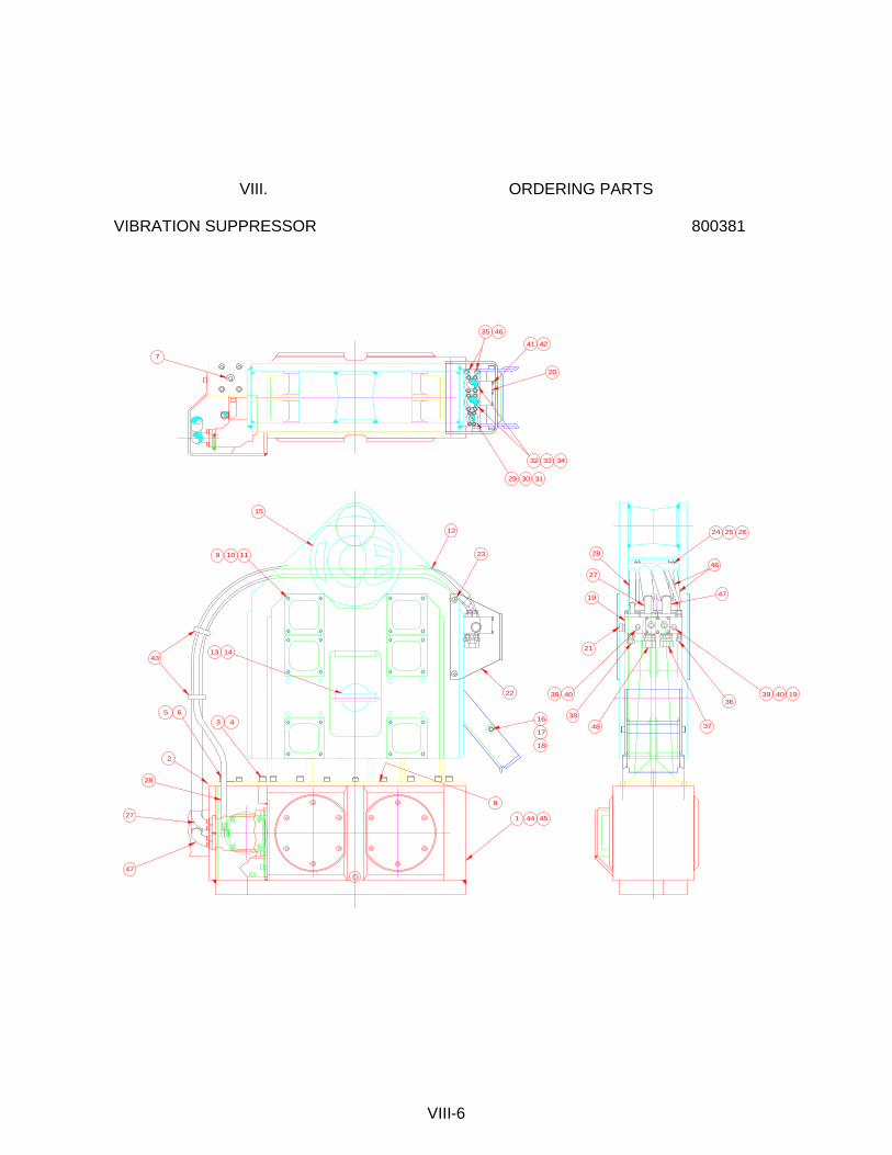
VIII. ORDERING PARTS VIBRATION SUPPRESSOR 800381
VIII-6
39 4036
39 40
21
32 33 34
20
19
38
48
41 42
37
29 30 31
24 25 26
22
23
1413
16
15
12
1110
1
2
6543
9
8
7
17
18
19
35
44 45
43
46
47
27
28
47
27
28
46
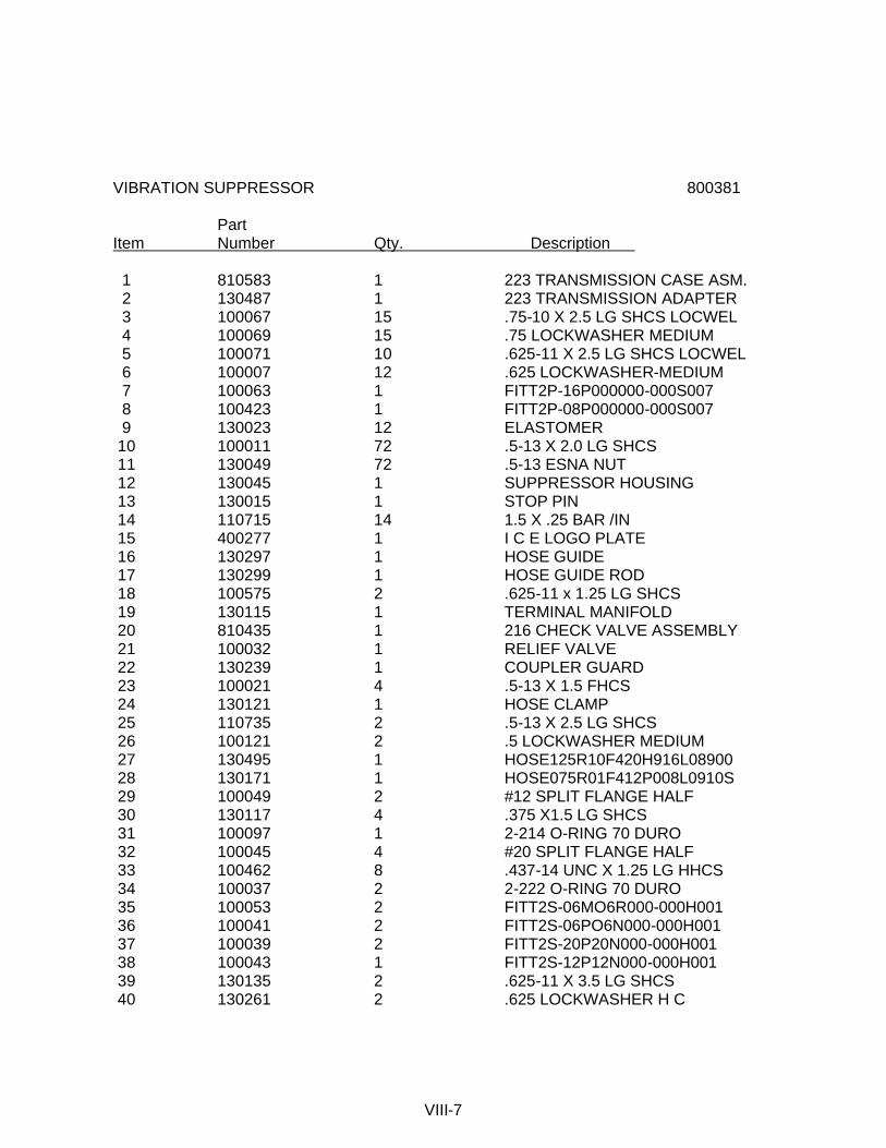
VIBRATION SUPPRESSOR 800381 Part Item Number Qty. Description 1 810583 1 223 TRANSMISSION CASE ASM. 2 130487 1 223 TRANSMISSION ADAPTER 3 100067 15 .75-10 X 2.5 LG SHCS LOCWEL 4 100069 15 .75 LOCKWASHER MEDIUM 5 100071 10 .625-11 X 2.5 LG SHCS LOCWEL 6 100007 12 .625 LOCKWASHER-MEDIUM 7 100063 1 FITT2P-16P000000-000S007 8 100423 1 FITT2P-08P000000-000S007 9 130023 12 ELASTOMER 10 100011 72 .5-13 X 2.0 LG SHCS 11 130049 72 .5-13 ESNA NUT 12 130045 1 SUPPRESSOR HOUSING 13 130015 1 STOP PIN 14 110715 14 1.5 X .25 BAR /IN 15 400277 1 I C E LOGO PLATE 16 130297 1 HOSE GUIDE 17 130299 1 HOSE GUIDE ROD 18 100575 2 .625-11 x 1.25 LG SHCS 19 130115 1 TERMINAL MANIFOLD 20 810435 1 216 CHECK VALVE ASSEMBLY 21 100032 1 RELIEF VALVE 22 130239 1 COUPLER GUARD 23 100021 4 .5-13 X 1.5 FHCS 24 130121 1 HOSE CLAMP 25 110735 2 .5-13 X 2.5 LG SHCS 26 100121 2 .5 LOCKWASHER MEDIUM 27 130495 1 HOSE125R10F420H916L08900 28 130171 1 HOSE075R01F412P008L0910S 29 100049 2 #12 SPLIT FLANGE HALF 30 130117 4 .375 X1.5 LG SHCS 31 100097 1 2-214 O-RING 70 DURO 32 100045 4 #20 SPLIT FLANGE HALF 33 100462 8 .437-14 UNC X 1.25 LG HHCS 34 100037 2 2-222 O-RING 70 DURO 35 100053 2 FITT2S-06MO6R000-000H001 36 100041 2 FITT2S-06PO6N000-000H001 37 100039 2 FITT2S-20P20N000-000H001 38 100043 1 FITT2S-12P12N000-000H001 39 130135 2 .625-11 X 3.5 LG SHCS 40 130261 2 .625 LOCKWASHER H C
VIII-7


VIBRATION SUPPRESSOR (Continued) 800381 Part Item Number Qty. Description 41 110177 6 .312-18 X 2.5 LG SHCS 42 100287 6 .312 LOCKWASHER 43 130243 2 RUBBER TIE DOWN 46 120193 2 HOSE038R02J006J006L132OS 47 130497 1 HOSE125R10F420H916L09200 48 100913 1 FITT2S-24N20P000-000H001
VIII-9
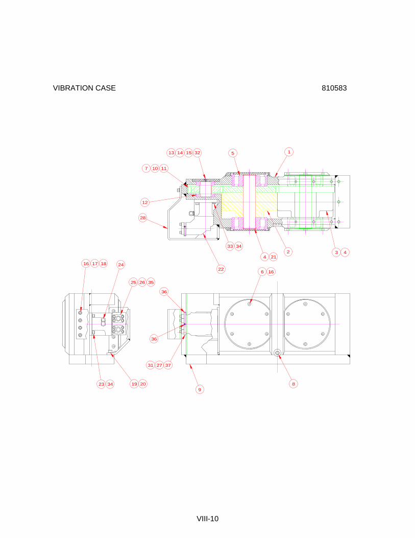
VIBRATION CASE 810583
VIII-10
19 20
13 14 15 5
241716
1110
22
25 26 35
28
33 34
23 34
2 3
8
6 16
372731
12
1
44 21
9
32
7
36
36
18
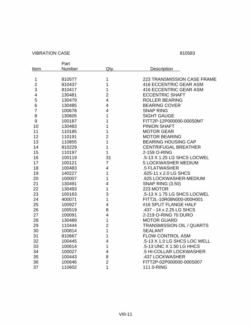
VIBRATION CASE 810583 Part Item Number Qty. Description 1 810577 1 223 TRANSMISSION CASE FRAME 2 810437 1 416 ECCENTRIC GEAR ASM 3 810417 1 416 ECCENTRIC GEAR ASM 4 130481 2 ECCENTRIC SHAFT 5 130479 4 ROLLER BEARING 6 130485 4 BEARING COVER 7 100678 4 SNAP RING 8 130605 1 SIGHT GAUGE 9 100187 1 FITT2P-12P000000-000S0M7 10 130483 1 PINION SHAFT 11 110185 1 MOTOR GEAR 12 110191 2 MOTOR BEARING 13 110855 1 BEARING HOUSING CAP 14 810229 1 CENTRIFUGAL BREATHER 15 110197 1 2-159 O-RING 16 100119 31 .5-13 X 1.25 LG SHCS LOCWEL 17 100121 7 5 LOCKWASHER MEDIUM 18 100483 4 .5 FLATWASHER 19 140227 1 .625-11 x 2.0 LG SHCS 20 100007 1 .625 LOCKWASHER-MEDIUM 21 130491 4 SNAP RING (3.50) 22 130493 1 223 MOTOR 23 100163 3 .5-13 X 1.75 LG SHCS LOCWEL 24 400071 1 FITT2L-10R08N000-000H001 25 100927 4 #16 SPLIT FLANGE HALF 26 100519 8 .437 - 14 x 2.25 LG SHCS 27 100091 4 2-219 O-RING 70 DURO 28 130489 1 MOTOR GUARD 29 110444 2 TRANSMISSION OIL / QUARTS 30 100814 1 SEALANT 31 810667 1 FLOW CONTROL ASM 32 100445 4 .5-13 X 1.0 LG SHCS LOC WELL 33 100614 1 .5-13 UNC X 1.50 LG HHCS 34 100027 4 .5 HI-COLLAR LOCKWASHER 35 100443 8 .437 LOCKWASHER 36 100646 2 FITT2P-02P000000-000S007 37 110602 1 111 0-RING
VIII-11

HOSE ASSEMBLIES - INTERCONNECTING 800029
VIII-12
RETURN
PRESSURE
DRAIN
CLAMP
UNCLAMP
5
989
10 11 13 1312
1717
1717
16
16
4 5
19
15
18
14
76
321
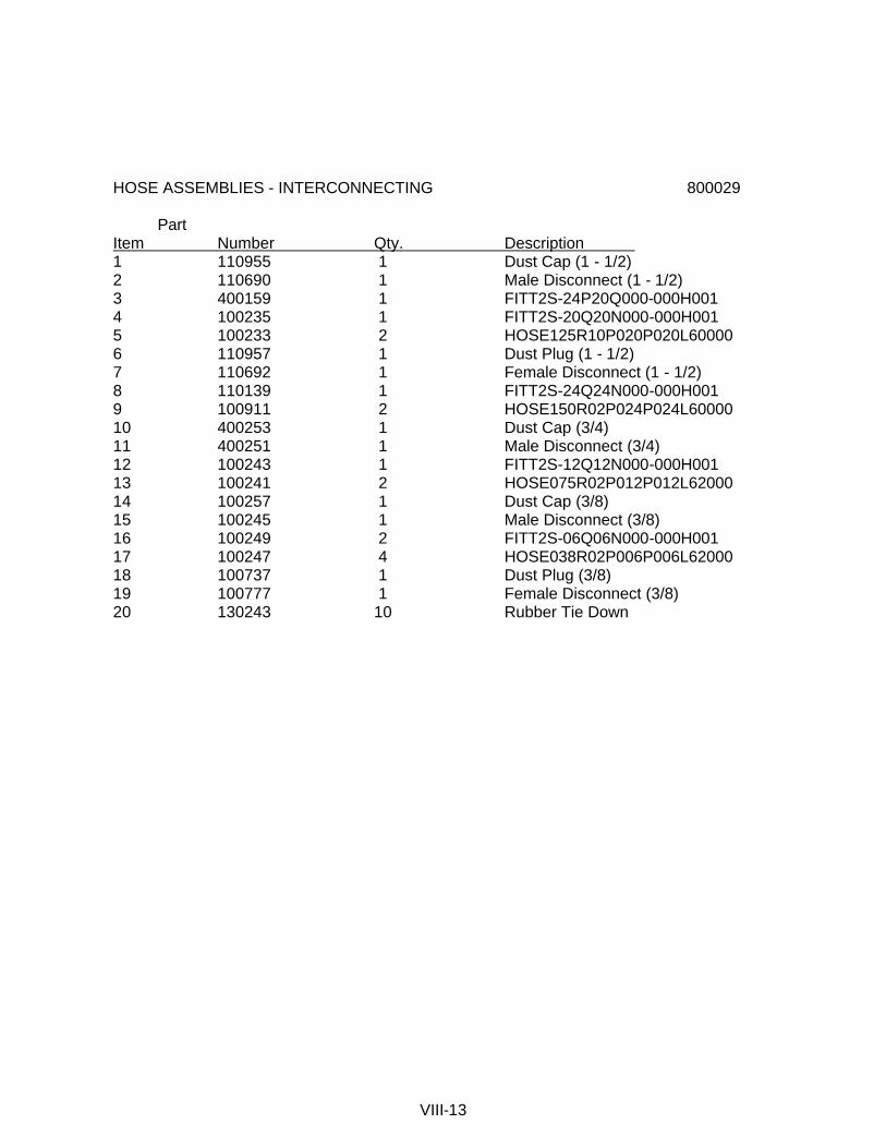
HOSE ASSEMBLIES - INTERCONNECTING 800029 Part Item Number Qty. Description 1 110955 1 Dust Cap (1 - 1/2) 2 110690 1 Male Disconnect (1 - 1/2) 3 400159 1 FITT2S-24P20Q000-000H001 4 100235 1 FITT2S-20Q20N000-000H001 5 100233 2 HOSE125R10P020P020L60000 6 110957 1 Dust Plug (1 - 1/2) 7 110692 1 Female Disconnect (1 - 1/2) 8 110139 1 FITT2S-24Q24N000-000H001 9 100911 2 HOSE150R02P024P024L60000 10 400253 1 Dust Cap (3/4) 11 400251 1 Male Disconnect (3/4) 12 100243 1 FITT2S-12Q12N000-000H001 13 100241 2 HOSE075R02P012P012L62000 14 100257 1 Dust Cap (3/8) 15 100245 1 Male Disconnect (3/8) 16 100249 2 FITT2S-06Q06N000-000H001 17 100247 4 HOSE038R02P006P006L62000 18 100737 1 Dust Plug (3/8) 19 100777 1 Female Disconnect (3/8) 20 130243 10 Rubber Tie Down
VIII-13
POWER UNIT - ENCLOSURE - 325 800379
VIII-14
1 6
2 6
4 6 5 36 6
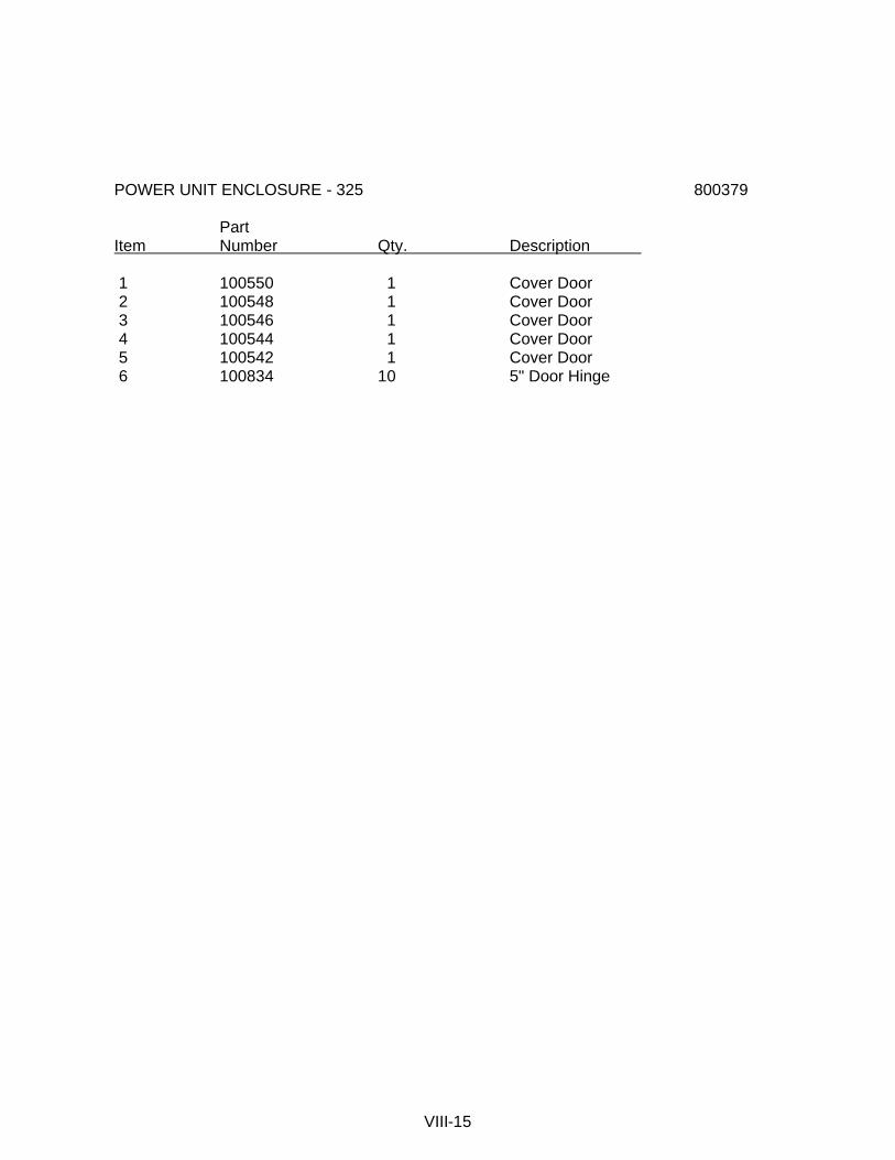
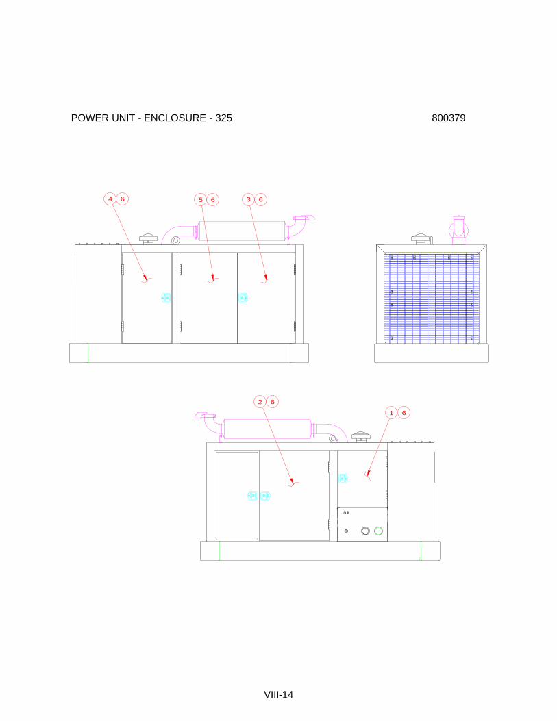
POWER UNIT ENCLOSURE - 325 800379 Part Item Number Qty. Description 1 100550 1 Cover Door 2 100548 1 Cover Door 3 100546 1 Cover Door 4 100544 1 Cover Door 5 100542 1 Cover Door 6 100834 10 5" Door Hinge
VIII-15

325 POWER UNIT - INTERNAL 800377
For view of power unit front elevation, return filter and electric throttle details see page VIII-18
VIII-16
1 30
123
150
29
4917112
51
46
48 47 2
153
44 47 45
47
122
123
61
62
9
11
10
12
8 119
52
140 147 148
115117116
149
113 114 115
104
17 18
21 22 23
24 25 23
111 92124931052627
2881
19
12
63
123
169
141
4135
4243
8592
40
8592
6869
7071
50
3
95
18
118
94
75
31
36
3732
33
34
35
31
36
59
160
143
144
54
152
55
56
57
58
130
109
146
4
5
6
145
64
65
106107 109
101 102 103
137 105
7 19 97
98 99 100
96 136 102
101 103 137
103102101
1041372015106
108
11010016
128135
165
166
167
168

325 POWER UNIT - INTERNAL 800377 Part Item Number Qty. Description 1 810563 1 325 P.U. FUEL BASE ASM 2 100508 1 3306TA DIESEL ENGINE 3 100512 1 MULTI-PUMP ADAPTER 4 100406 2 MAIN PUMP(F12-110) 5 100587 8 .75-10 HEX NUT 6 100589 8 .75 FLATWASHER 7 100684 1 CLAMP PUMP 8 100552 1 RESERVOIR (325) 9 400129 1 RESERVOIR COVER 10 400225 1 RESERVOIR GASKET 11 100648 32 .375-16 X.875 LG SHCS 12 400149 39 .375 LOCKWASHER 13 100520 2 RETURN FILTER ASM. 14 100518 4 RETURN FILTER ELEMENT 15 810571 1 325 DRIVE MANIFOLD ASM. 16 810449 1 570C CLAMP MANIFOLD ASM. 17 100119 3 .5-13 X 1.25 LG SHCS LOCWEL 18 100121 11 .5 LOCKWASHER MEDIUM 19 100051 6 .375-16 X 1.0 LG SHCS LOCWEL 20 100534 1 COUPLER PANEL (325) 21 110690 1 1.5 MALE DISCONNECT 22 110955 1 1.5 DUST CAP 23 110392 2 FITT2S-24R24P000-000H001 24 110692 1 1.5 FEMALE DISCONNECT 25 110957 1 1.5 DUST PLUG 26 400095 1 .75 FEMALE DISCONNECT 27 400121 1 .75 DUST PLUG 28 100387 1 FITT2S-12P12B000-000H001 29 810585 1 325 CONTROL BOX ASM. 30 100558 1 TOOL BOX 31 400890 2 BATTERY 32 400888 1 BATTERY HOLDDOWN 33 400231 3 HOLD DOWN STUD 34 100831 3 .312 WING NUT 35 100293 19 .312 FLATWASHER 36 100537 2 BATTERY CABLE-24" 37 110653 1 BATTERY CABLE-6 38 100873 1 RIGHT HEAT EXCHANGE BKT 39 100871 1 LEFT HEAT EXCHANGE BKT 40 400099 1 HEAT EXCHANGER 41 100105 16 312-18 X 1.0 LG SHCS LOCWEL 42 100287 18 .312 LOCKWASHER 43 100289 16 .312-18 HEX NUT
VIII-17
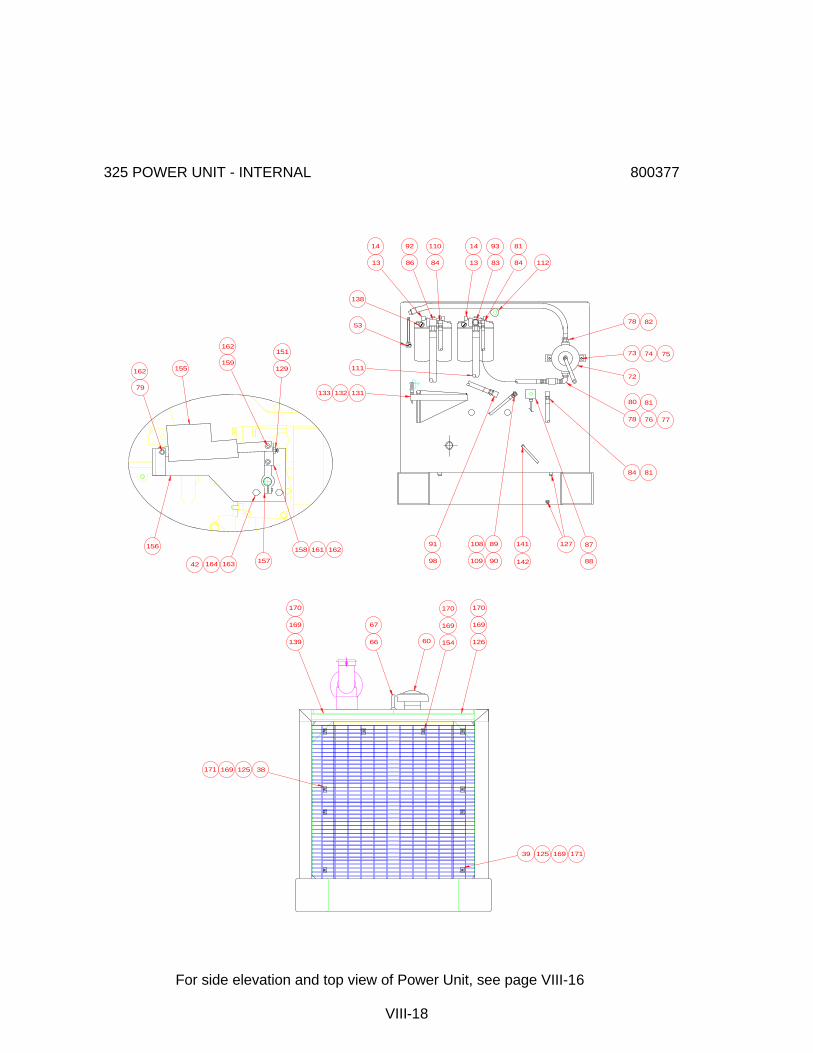
325 POWER UNIT - INTERNAL 800377
For side elevation and top view of Power Unit, see page VIII-16
VIII-18
127141
142
87
88
89
90
108
109
91
98
131132133
111
53
138
13
14
86
92
84
110
13
14
83
93
84
81
112
78 82
72
73 74 75
78 76 77
80 81
84 81
155
156
157
158
79
162
16316442
159
162
161 162
129
151
169 38125
139
169
171
170
66
67
154
170
169
60
169
170
126
39 125 169 171

325 POWER UNIT - INTERNAL 800377 Part Item Number Qty. Description 44 400898 1 MUFFLER 45 100516 1 EXHAUST ELBOW (5"-LG.) 46 400894 1 EXHAUST OUTLET ELBOW 47 140369 3 5 IN. U-CLAMP 48 140411 1 5.0 RAIN CAP 49 100532 1 MUFFLER SUPPORT 50 100726 7 ANTIFREEZE/GAL 51 100535 2 .375 -16 HEX NUT 52 400277 1 I C E LOGO PLATE 53 130179 1 SIGHT GAUGE & THERMOMETER 54 120611 1 WATER SEPERATOR ASM. 55 120425 1 FITT2S-16P16P000-1000301 56 110706 1 FITT2S-16P08Q000-000H001 57 110173 1 FITT2S-08M08P000-000H001 58 110377 2 FITT2L-16P16Q000-0000306 59 110633 1 HOSE038R02J006J006L0370S 60 100514 1 AIR INTAKE BONNET 61 100951 20 FLEXHAUST/IN 62 130237 2 HOSE CLAMP 63 100540 1 UNIT COVER(325) 64 100417 1 FITT2C-48Q000000-0000306 65 100419 1 PETCOCK 66 100460 1 1.25-7 X12 LG EYE BOLT 67 100722 1 ROLL PIN .25 X 3.5 68 100071 4 .625-11 X 2.5 LG SHCS LOCWEL 69 130141 4 .625 FLAT WASHER 70 100007 4 .625 LOCKWASHER-MEDIUM 71 100273 4 .625-11 HEX NUT 72 100447 1 HAND PUMP 73 100439 2 .437-X1.75 LG SHCS 74 400153 2 .437 FLATWASHER 75 100443 14 .437 LOCKWASHER 76 100449 1 FITT2S-16P16P000-000H001 77 100451 1 CHECK VALVE 78 110089 2 FITT2S-20P16Q000-000H001 79 110163 1 .25-20 X 3.5 LG SHCS 80 300119 1 FITT2S-16P12M000-000H001 81 130201 2 HOSE075R01J012J012L04000 82 400215 1 HOSE100R01P016P016L08400 83 810573 1 SPECIAL TEE 84 100489 3 FITT2L-12M12P000-0000001 85 100588 2 FITT2L-24M24P000-0000001 86 810575 1 SPECIAL 90 ELBOW
VIII-19

325 POWER UNIT - INTERNAL 800377 Part Item Number Qty. Description 87 400115 1 TEMPERATURE SWITCH 88 110237 1 STR S/O CORD ADAPTER 89 400409 1 FITT2S-12P08Q000-000H001 90 300401 1 FITT2T-08M08P08M-0000001 91 120055 1 FITT2L-16M16P000-0000001 92 100500 2 HOSE150R01J024J024L11800 93 100498 1 HOSE150R02J924J024L07200 94 100462 12 .437-14 UNC X 1.25 LG HHCS 95 100445 8 .5-13 X 1.0 LG SHCS LOC WELL 96 100454 2 2"TUBE FLEX MASTER 97 100783 1 FITT2L-16M16R000-000H001 98 100862 1 HOSE100R01J016J016L03300 99 100933 1 FITT2L-10R08M000-000H001 100 110461 1 HOSE050R09J008J008L04000 101 810309 8 SPECIAL SPLIT FLG HALF 102 100037 4 2-222 O-RING 70 DURO 103 400951 16 14 MM X 55 MM LG HHCS 104 100492 1 HOSE100PT4J020H020L04000 105 100490 1 HOSE100PT4J020H920L06500 106 110984 2 FITT2S-12S08M000-000H0F1 107 100488 1 FITT2V-08M08J000-000H001 108 100486 1 HOSE050R01J008J008L01450 109 110265 2 HOSE050R01J008J008L02300 110 100484 1 HOSE075R01J012J012L08400 111 100482 1 HOSE150R02J024J024L07200 112 100455 1 BREATHER 113 100777 1 .375 FEMALE DISCONNECT 114 100737 1 .375 DUST PLUG 115 110794 2 FITT2S-06P06P000-000H001 116 100245 1 .375 MALE DISCONNECT 117 100257 1 .375 DUST CAP 118 100735 2 TRANSMISSION OIL/GAL 119 140415 275 HYDRAULIC FLUID/GAL 122 100536 1 EXHAUST SHIELD 123 130209 15 .25-14 X 1 HEX TEX 124 110680 1 HOSE019RO1J004J004L40000 125 100404 2 INTAKE GRILL (325) 126 100400 1 LEFT EXHAUST GRILL 127 100423 4 FITT2P-08P000000-000S007 128 120523 2 FUEL BASE MAGNET 129 110827 1 10-32 X .75 BHCS S.S. 130 110819 1 SUCTION FILTER TUBE 131 810045 1 HEX KEY GROUP
VIII-20
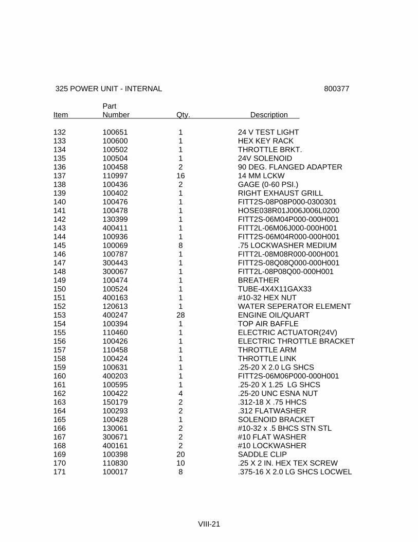
325 POWER UNIT - INTERNAL 800377 Part Item Number Qty. Description 132 100651 1 24 V TEST LIGHT 133 100600 1 HEX KEY RACK 134 100502 1 THROTTLE BRKT. 135 100504 1 24V SOLENOID 136 100458 2 90 DEG. FLANGED ADAPTER 137 110997 16 14 MM LCKW 138 100436 2 GAGE (0-60 PSI.) 139 100402 1 RIGHT EXHAUST GRILL 140 100476 1 FITT2S-08P08P000-0300301 141 100478 1 HOSE038R01J006J006L0200 142 130399 1 FITT2S-06M04P000-000H001 143 400411 1 FITT2L-06M06J000-000H001 144 100936 1 FITT2S-06M04R000-000H001 145 100069 8 .75 LOCKWASHER MEDIUM 146 100787 1 FITT2L-08M08R000-000H001 147 300443 1 FITT2S-08Q08Q000-000H001 148 300067 1 FITT2L-08P08Q00-000H001 149 100474 1 BREATHER 150 100524 1 TUBE-4X4X11GAX33 151 400163 1 #10-32 HEX NUT 152 120613 1 WATER SEPERATOR ELEMENT 153 400247 28 ENGINE OIL/QUART 154 100394 1 TOP AIR BAFFLE 155 110460 1 ELECTRIC ACTUATOR(24V) 156 100426 1 ELECTRIC THROTTLE BRACKET 157 110458 1 THROTTLE ARM 158 100424 1 THROTTLE LINK 159 100631 1 .25-20 X 2.0 LG SHCS 160 400203 1 FITT2S-06M06P000-000H001 161 100595 1 .25-20 X 1.25 LG SHCS 162 100422 4 .25-20 UNC ESNA NUT 163 150179 2 .312-18 X .75 HHCS 164 100293 2 .312 FLATWASHER 165 100428 1 SOLENOID BRACKET 166 130061 2 #10-32 x .5 BHCS STN STL 167 300671 2 #10 FLAT WASHER 168 400161 2 #10 LOCKWASHER 169 100398 20 SADDLE CLIP 170 110830 10 .25 X 2 IN. HEX TEX SCREW 171 100017 8 .375-16 X 2.0 LG SHCS LOCWEL
VIII-21
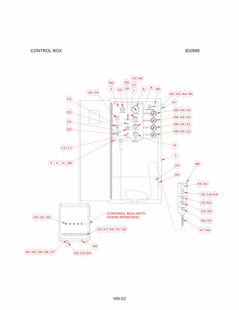
CONTROL BOX 810585
VIII-22
DRIVE - FORWARD
BRAKE - REVERSE
CLOSE
OPEN
TACHOMETER
ENG OIL PRESS.
ENG WATER TEMP.
AMMETER
HOUR METER
HYD FLUID COLD
MAIN POWER
ONSTOP START
CLOSE
CLAMP
OPEN CLOSE
FOR.OFF
REV.
ENGINE THROTTLE
REMOTE - LOCAL
FOR.OFF
REV.
CLOSEOPEN
CLOSE
EMERGENCY STOP
48
58
2 10 16
30
7
11
12 40
6 60
42 43 44 45
57
59 46 20
59 46 22
59 46 21
59 46 21
9
1
24
25
41
FASTSLOW
61
6750
23 53
23 55
18 19 54
4726 27 29 31 32
62 63 64
33 3534
3739 3866 65
49
56
8
1918
15
23
14
23
365
13 17
3 4
CONTROL BOX WITHDOOR REMOVED
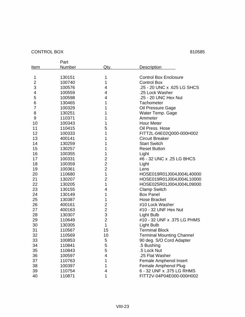
CONTROL BOX 810585 Part Item Number Qty. Description 1 130151 1 Control Box Enclosure 2 100740 1 Control Box 3 100576 4 .25 - 20 UNC x .625 LG SHCS 4 100559 4 .25 Lock Washer 5 100598 4 .25 - 20 UNC Hex Nut 6 130465 1 Tachometer 7 100329 1 Oil Pressure Gage 8 130251 1 Water Temp. Gage 9 110371 1 Ammeter 10 100343 1 Hour Meter 11 110415 5 Oil Press. Hose 12 100333 1 FITT2L-04E02Q000-000H002 13 400141 1 Circuit Breaker 14 130259 1 Start Switch 15 130257 1 Reset Button 16 100355 1 Light 17 100331 2 #6 - 32 UNC x .25 LG BHCS 18 100359 2 Light 19 100361 2 Lens 20 110680 1 HOSE019R01J004J004L40000 21 130207 2 HOSE019R01J004J004L10000 22 130205 1 HOSE025R01J004J004L09000 23 130155 4 Clamp Switch 24 130149 1 Box Panel 25 130387 1 Hose Bracket 26 400161 2 #10 Lock Washer 27 400163 2 #10 - 32 UNF Hex Nut 28 130307 3 Light Bulb 29 110649 2 #10 - 32 UNF x .375 LG PHMS 30 130305 1 Light Bulb 31 110567 15 Terminal Block 32 110569 10 Terminal Mounting Channel 33 100853 5 90 deg. S/O Cord Adapter 34 110841 5 .5 Bushing 35 110843 5 .5 Lock Nut 36 100597 4 .25 Flat Washer 37 110763 1 Female Amphenol Insert 38 100397 1 Female Amphenol Plug 39 110754 4 6 - 32 UNF x .375 LG RHMS 40 110871 1 FITT2V-04P04E000-000H002
VIII-23

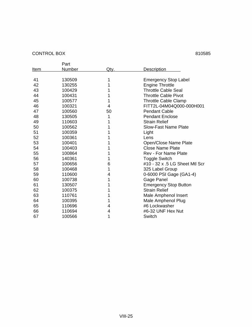
CONTROL BOX 810585 Part Item Number Qty. Description 41 130509 1 Emergency Stop Label 42 130255 1 Engine Throttle 43 100429 1 Throttle Cable Seal 44 100431 1 Throttle Cable Pivot 45 100577 1 Throttle Cable Clamp 46 100321 4 FITT2L-04M04Q000-000H001 47 100560 50 Pendant Cable 48 130505 1 Pendant Enclose 49 110603 1 Strain Relief 50 100562 1 Slow-Fast Name Plate 51 100359 1 Light 52 100361 1 Lens 53 100401 1 Open/Close Name Plate 54 100403 1 Close Name Plate 55 100864 1 Rev - For Name Plate 56 140361 1 Toggle Switch 57 100656 6 #10 - 32 x .5 LG Sheet Mtl Scr 58 100468 1 325 Label Group 59 110600 4 0-6000 PSI Gage (GA1-4) 60 100738 1 Gage Panel 61 130507 1 Emergency Stop Button 62 100375 1 Strain Relief 63 110761 1 Male Amphenol Insert 64 100395 1 Male Amphenol Plug 65 110696 4 #6 Lockwasher 66 110694 4 #6-32 UNF Hex Nut 67 100566 1 Switch
VIII-25

CONTROL MANIFOLD ASSEMBLY 810571
VIII-26
FOR REV
FORGAGE(400°)
DRAIN
BY-PASS
COOLER
P1
P2
FOR315100
REV
FILTER
25
1815
8
20
16
13
12 16
30
23 32
REVGAGE
2928
17
119
10
5
3
23
4
19
3435
27
33
2
26
2423
31
1
21
22
46 7

CONTROL MANIFOLD ASSEMBLY 810571 Part Item Number Qty. Description 1 100758 1 Manifold Block 2 110628 1 Cooler Valve (V-3) 3 100588 2 FITT2L-24M24P000-0000001 4 110203 2 FITT2S-04M04P000-000H001 5 100547 2 FITT2S-32P24Q000-000H306 6 400039 16 .75-10 UNC x 2.75 LG SHCS 7 100069 16 .75 Lockwasher 8 100654 1 Sandwich Shut-Off Valve (V-4) 9 100143 4 .375-16 UNC x 1.25 LG SHCS 10 400149 4 .375 Lockwasher 11 110544 1 Cartridge Cover (CC4) 12 110530 1 Cartridge Cover (CC1) 13 110606 1 Cartridge Cover (CC2) 14 110546 1 Cartridge Cover (CC3) 15 100650 4 .25-20 UNC x 4.5 LG SHCS 16 110624 2 Cartridge A 17 110622 2 Cartridge B 18 810519 1 Modified Spool Valve (V2) 19 100845 2 FITT2P-04P000000-000S007 20 110602 3 111-O-Ring 21 140581 1 FITT2L-06M04P000-0000001 22 100556 1 F1TT2T-04M04M04J-0000001 23 100145 3 FITT2L-04M04P000-0000001 24 100149 1 HOSE025R02J004J004L01900 25 140387 1 Orifice - .059 Dia. 26 100608 1 Special Tee 27 130339 1 1.5 Check Valve (CV-2) 28 100630 1 Rev. Cartridge (100) (RV4) 29 100632 1 For. Cartridge (315) (RV1) 30 100646 2 FITT2P-02P000000-000S007 31 100990 2 Electric Connector 32 100719 1 HOSE025R02J004J004L03000 33 100565 1 FITT2S-24M24P000-000H001 34 100446 1 FITT2L-24P24Q000-0000001 35 110037 1 FITT2S-24P24P000-000H001
VIII-27

CLAMP MANIFOLD 810449
VIII-28
OPEN CLOSE
RELIF ADJ
CLOSE OPEN12
1
2
3910
4
CLOSE
5 11910
GAGE
OPEN
GAGE
638PUMP
RETURN7
6

CLAMP MANIFOLD 810449 Part Item Number Qty. Description 1 110642 1 Manifold Block 2 110149 1 Check Valve (CV-5) 3 810033 1 Pressure Switch (PS-1) 4 100898 1 Relief Valve (RV2) 5 110147 1 4-way Solenoid Valve (V-1) 6 140539 2 FITT2L-04M02P000-0000001 7 110632 1 FITT2L-12M06P000-000H001 8 110630 1 FITT2S-08M06P000-000H001 9 110885 1 Conduit Adapter 10 110235 1 90 deg. S/O Cord Adapter 11 110634 4 .25 - 20 UNC x 7.50 LG SHCS 12 400213 2 FITT2P-06P000000-000S007
VIII-29

126B CLAMP ASSEMBLY (OPTIONAL) 800327
VIII-30

126B CLAMP ASSEMBLY (OPTIONAL) 800327 Part Item Number Qty. Description 1 810493 1 126B Clamp Body Asm. 2 810491 1 Cylinder 3 100212 12 1-8 UNC x 4.0 LG. SHCS 4 100209 19 1" Lockwasher 5 120567 1 Rod End Cap 6 120569 1 Piston 7 100213 7 1-8 UNC x 2.50 LG. SHCS 8 120575 1 Cylinder Rod 9 120347 1 261-O- Ring (Note) 10 120285 2 Piston Bearing (Note) 11 120283 2 Piston Seal (Note) 12 120555 1 Rod Bearing (Note) 13 120553 1 Rod Seal (Note) 14 100983 1 Pile Guide 15 120401 1 2-269 O-RING 90 DURO (Note) 16 130057 2 FITT2L-06M06R000-000H001 17 100229 1 Grease Fitting 18 100193 8 1.5-6 UNC x 5.0 LG. SHCS 19 100195 8 1.5 Lockwasher 20 100791 1 Clamp Label 21 130381 4 Rivet 22 120009 2 HOSE038R02J006J006L0960S 25 100230 2 FITT2P-06M000000-000T001 26 810515 1 126B Seal Kit 27 810495 1 Universal Movable Jaw 28 110515 1 Universal Fixed Jaw 29 810497 1 H-Beam Movable Jaw 30 110541 1 H-Beam Fixed Jaw 31 810499 1 DS-Movable Jaw 32 110419 1 DS-Fixed Jaw 33 130449 1 Spiral Roll Pin 34 120629 1 Holding Valve Note; Included in 126B Seal Kit.
VIII-31
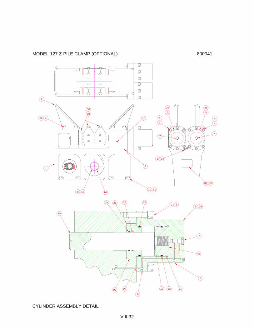
MODEL 127 Z-PILE CLAMP (OPTIONAL) 800041
CYLINDER ASSEMBLY DETAIL
VIII-32
1514 16
1
2
43
29
30
15
8
10 11
31 32
179
7
6
4
5
26 26
5
6
4
7
27 28
8
19 2122
8
20
7
5 266 4
22232524
18

MODEL 127 Z-PILE CLAMP (OPTIONAL) 800041 Part Item Number Qty. Description 1 810059 1 127 Z CLAMP BODY CASTING 2 120677 2 PILE GUIDE 3 100213 8 1.0-8 X 2.5 LG SHCS LOCWEL 4 100209 20 1.0 LOCKWASHER MEDIUM 5 120659 2 127B CYLINDER 6 100212 12 1.0-8 X 4 LG SHCS LOCWEL 7 120629 2 HOLDING VALVE CARTRIDGE 8 100646 10 FITT2P-02P000000-000S007 9 100053 2 FITT2S-06MO6R000-000H001 10 100193 8 1.5-6 X 5.0 LG SHCS 11 100195 8 1.5 LOCKWASHER EXTRA HEAVY 14 120155 1 SHAFT 15 100229 4 GREASE FITTING 16 120191 2 RETAINER RING 17 120009 2 HOSE038R02J006J006L0960S 18 120663 2 CYLINDER ROD(127B) 19 120239 2 2-132 O-RING 20 120241 2 PISTON-127 21 120243 4 PISTON BEARING 22 120245 4 PISTON SEAL 23 120665 2 ROD BEARING (127B) 24 120667 2 ROD SEAL (127B) 25 120347 2 2-261 O-RING 90 DURO 26 810629 2 127B Z SEAL KIT 27 120661 2 ROD END CAP(127B) 28 110602 4 111 0-RING 29 800419 1 12" MULTI-GRIP JAW SET (Note) 30 800417 1 13" MULTI-GRIP JAW SET (Note) 31 120181 1 127 S/N PLATE 32 130381 4 RIVET Note : Not part of Final Assembly.
VIII-33

10 FOOT CLAMP EXTENSION (OPTIONAL) 800423 90 DEG. CLAMP ADAPTER (OPTIONAL) 800049
VIII-34
2 3
1
1
2 3
4 5

10 FOOT CLAMP EXTENSION (OPTIONAL) 800423 Part Item Number Qty. Description 1 810655 1 10' Extension 2 100193 10 1.50-6 UNC x 5.00 LG. SHCS 3 100195 10 1.50 Lockwasher 4 120193 2 HOSE038R02J006J006L1320S 5 120081 2 FITT2S-06M06M000-000H001 90 Deg. CLAMP ADAPTER (OPTIONAL) 800049 Part Item Number Qty. Description 1 120083 1 90 deg. Clamp Adapter 2 120077 8 1.50-6 UNC x 3.50 LG SHCS 3 130219 8 1.50 Hi-Collar Lockwasher
VIII-35
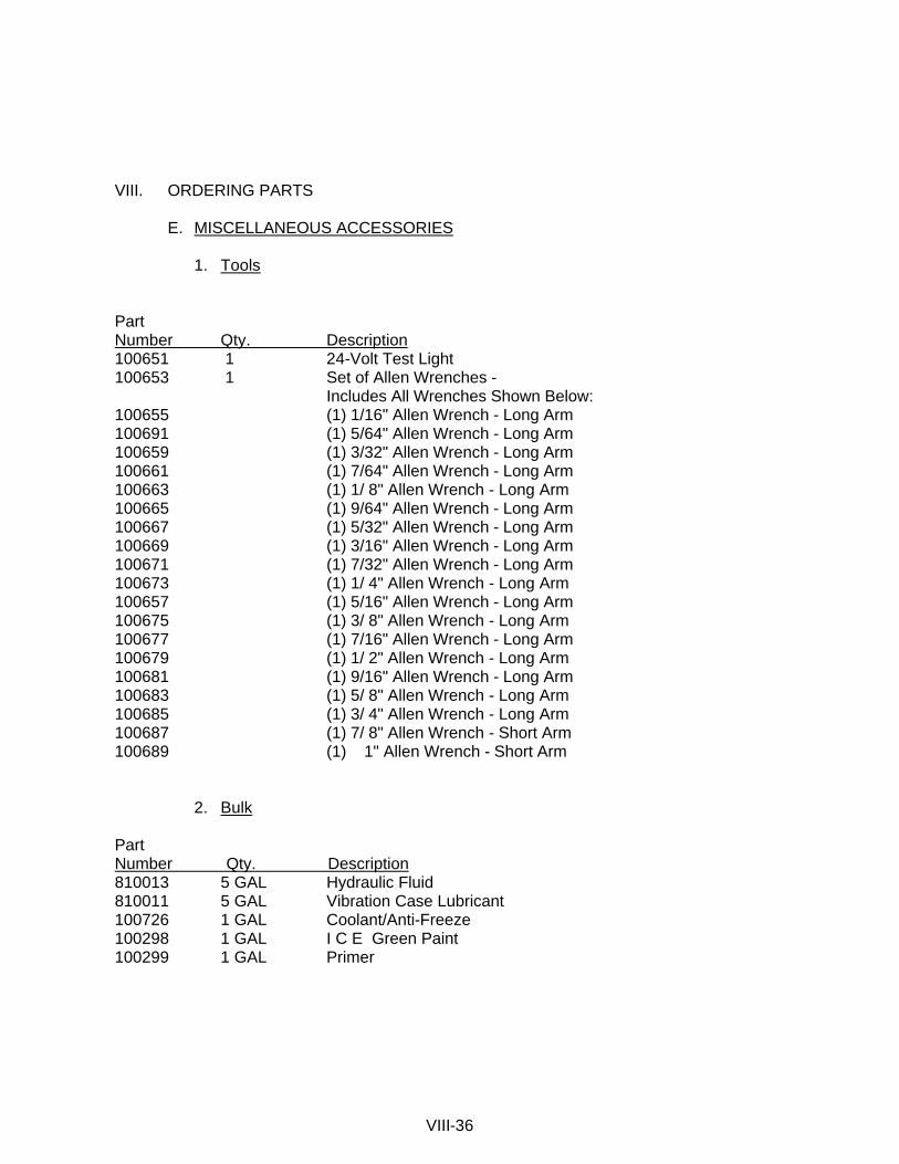
VIII. ORDERING PARTS E. MISCELLANEOUS ACCESSORIES 1. Tools Part Number Qty. Description 100651 1 24-Volt Test Light 100653 1 Set of Allen Wrenches - Includes All Wrenches Shown Below: 100655 (1) 1/16" Allen Wrench - Long Arm 100691 (1) 5/64" Allen Wrench - Long Arm 100659 (1) 3/32" Allen Wrench - Long Arm 100661 (1) 7/64" Allen Wrench - Long Arm 100663 (1) 1/ 8" Allen Wrench - Long Arm 100665 (1) 9/64" Allen Wrench - Long Arm 100667 (1) 5/32" Allen Wrench - Long Arm 100669 (1) 3/16" Allen Wrench - Long Arm 100671 (1) 7/32" Allen Wrench - Long Arm 100673 (1) 1/ 4" Allen Wrench - Long Arm 100657 (1) 5/16" Allen Wrench - Long Arm 100675 (1) 3/ 8" Allen Wrench - Long Arm 100677 (1) 7/16" Allen Wrench - Long Arm 100679 (1) 1/ 2" Allen Wrench - Long Arm 100681 (1) 9/16" Allen Wrench - Long Arm 100683 (1) 5/ 8" Allen Wrench - Long Arm 100685 (1) 3/ 4" Allen Wrench - Long Arm 100687 (1) 7/ 8" Allen Wrench - Short Arm 100689 (1) 1" Allen Wrench - Short Arm 2. Bulk Part Number Qty. Description 810013 5 GAL Hydraulic Fluid 810011 5 GAL Vibration Case Lubricant 100726 1 GAL Coolant/Anti-Freeze 100298 1 GAL I C E Green Paint 100299 1 GAL Primer
VIII-36

VIII. ORDERING PARTS E. MISCELLANEOUS ACCESSORIES (CONTINUED) 3. 223 Hose Group Kit - Internal 850123 Page Item P/N Qty. Description Ref. 27 130495 1 HOSE125R10F420H916L08900 VIII-6 28 130171 1 HOSE075R01F412P008L0910S VIII-6 46 120193 2 HOSE038R02J006J006L132OS VIII-6 47 130497 1 HOSE125R10F420H916L09200 VIII-6 4. 325 Hose Group Kit - Internal 850105 Page Item P/N Qty. Description Ref. 59 110633 1 HOSE038R02J006J006L0370S VIII-19 81 130201 2 HOSE075R01J012J012L04000 VIII-20 82 400215 1 HOSE100R01P016P016L08400 VIII-20 92 100500 2 HOSE150R01J024J024L18000 VIII-20 93 100498 1 HOSE150R02J924J024L07200 VIII-20 98 100862 1 HOSE100R01J016J016L03300 VIII-20 100 110461 1 HOSE050R09J008J008L04000 VIII-20 104 100492 1 HOSE100PT4J020H020L04000 VIII-20 105 100490 1 HOSE100PT4J020H920L06500 VIII-20 108 100486 1 HOSE050R01J008J008L01450 VIII-20 109 110265 1 HOSE050R01J008J008L02300 VIII-20 110 100484 1 HOSE075R01J012J012L08400 VIII-20 111 100482 1 HOSE150R02J024J024L07200 VIII-20
VIII-37
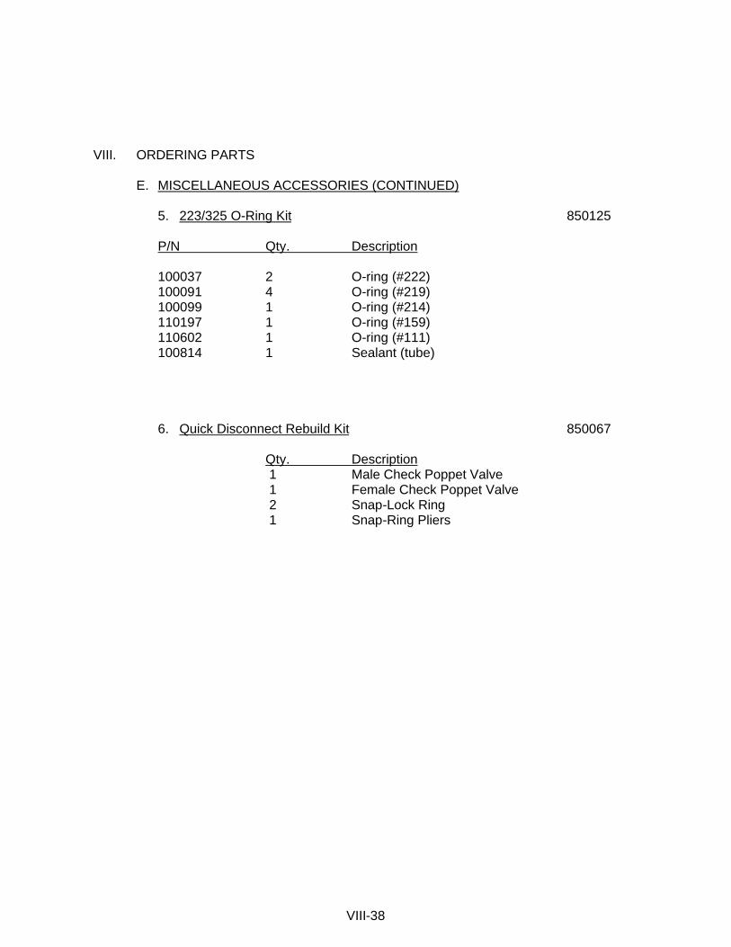
VIII. ORDERING PARTS E. MISCELLANEOUS ACCESSORIES (CONTINUED) 5. 223/325 O-Ring Kit 850125
P/N Qty. Description 100037 2 O-ring (#222) 100091 4 O-ring (#219) 100099 1 O-ring (#214) 110197 1 O-ring (#159) 110602 1 O-ring (#111) 100814 1 Sealant (tube)
6. Quick Disconnect Rebuild Kit 850067
Qty. Description 1 Male Check Poppet Valve 1 Female Check Poppet Valve 2 Snap-Lock Ring 1 Snap-Ring Pliers
VIII-38
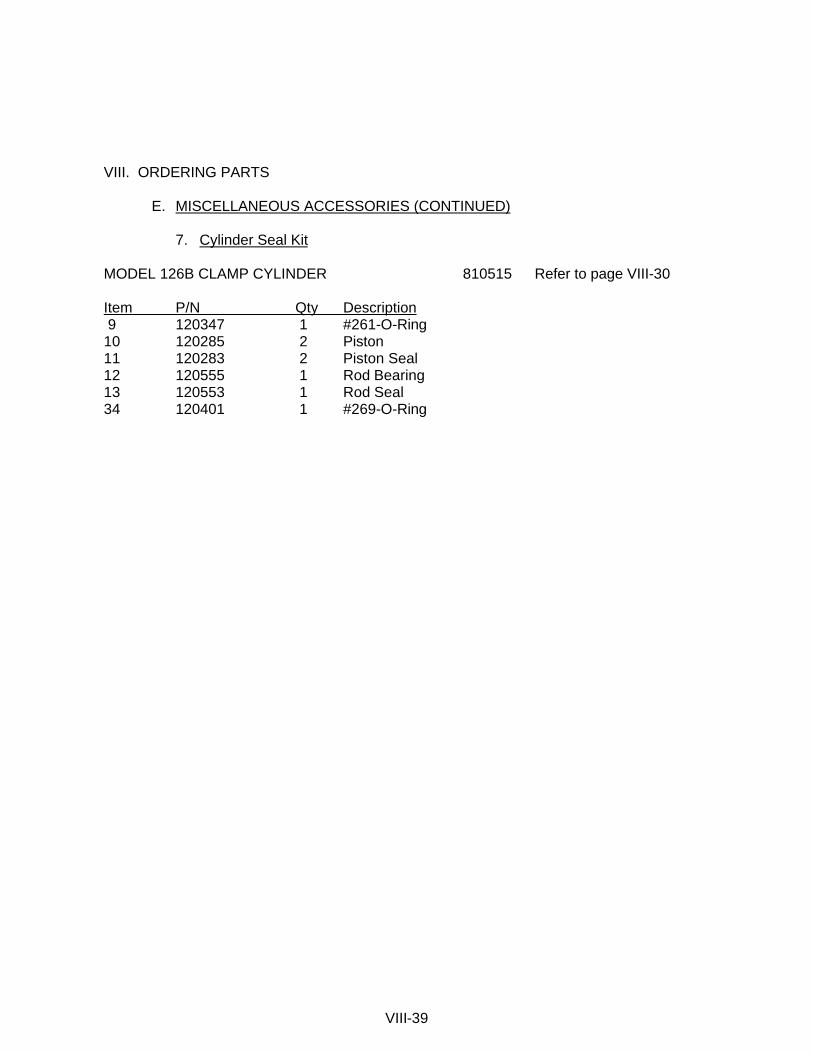
VIII. ORDERING PARTS E. MISCELLANEOUS ACCESSORIES (CONTINUED) 7. Cylinder Seal Kit MODEL 126B CLAMP CYLINDER 810515 Refer to page VIII-30 Item P/N Qty Description 9 120347 1 #261-O-Ring 10 120285 2 Piston 11 120283 2 Piston Seal 12 120555 1 Rod Bearing 13 120553 1 Rod Seal 34 120401 1 #269-O-Ring
VIII-39

VIII. ORDERING PARTS F. RECOMMENDED SPARE PARTS VIBRATION SUPPRESSOR 800381 Refer to page VIII-6 Item P/N Qty. Description 9 130023 1 Elastomer 21 100032 1 Relief Valve VIBRATION CASE 810583 Refer to page VIII-10 Item P/N Qty. Description 8 130605 1 Sight Gage -- 110607 2 Motor Shaft Seal 29 100814 1 Sealant (Tube) HOSE ASSEMBLIES-INTERCONNECTING 800029 Refer to page VIII-12 Item P/N Qty Description 5 100233 2 HOSE125R10P020P020L60000 9 100911 2 HOSE150R02P024P024L60000 13 100241 2 HOSE075R02P012P012L62000 17 100247 4 HOSE038R02P006P006L62000 POWER UNIT - INTERNAL (325) 800377 Refer to page VIII-16/18 Item P/N Qty Description -- 100233 1 Oil Filter 14 100518 4 Hyd.Oil Filter -- 100450 1 Fuel Filter Element -- 100448 1 Air Filter Element 100 110461 1 HOSE050R09J008J008L04000 104 100492 1 HOSE100PT4J020H020L04000 105 100490 1 HOSE100PT4J020H020L06500
VIII-40
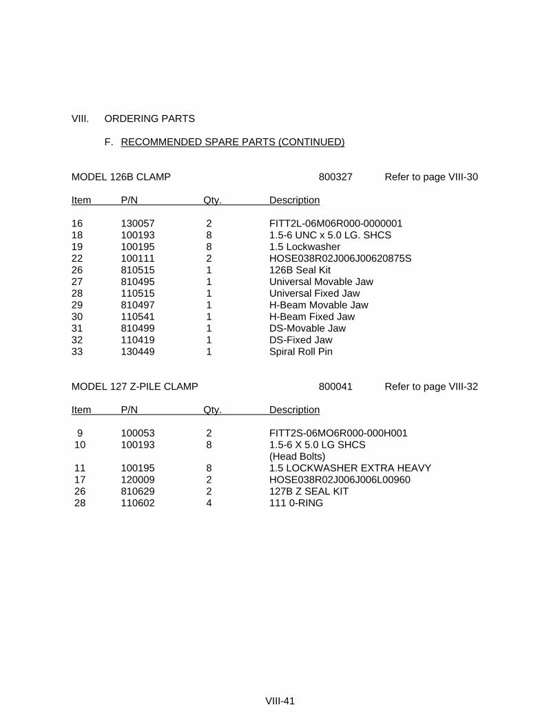
VIII. ORDERING PARTS F. RECOMMENDED SPARE PARTS (CONTINUED) MODEL 126B CLAMP 800327 Refer to page VIII-30 Item P/N Qty. Description 16 130057 2 FITT2L-06M06R000-0000001 18 100193 8 1.5-6 UNC x 5.0 LG. SHCS 19 100195 8 1.5 Lockwasher 22 100111 2 HOSE038R02J006J00620875S 26 810515 1 126B Seal Kit 27 810495 1 Universal Movable Jaw 28 110515 1 Universal Fixed Jaw 29 810497 1 H-Beam Movable Jaw 30 110541 1 H-Beam Fixed Jaw 31 810499 1 DS-Movable Jaw 32 110419 1 DS-Fixed Jaw 33 130449 1 Spiral Roll Pin MODEL 127 Z-PILE CLAMP 800041 Refer to page VIII-32 Item P/N Qty. Description 9 100053 2 FITT2S-06MO6R000-000H001 10 100193 8 1.5-6 X 5.0 LG SHCS (Head Bolts) 11 100195 8 1.5 LOCKWASHER EXTRA HEAVY 17 120009 2 HOSE038R02J006J006L00960 26 810629 2 127B Z SEAL KIT 28 110602 4 111 0-RING
VIII-41

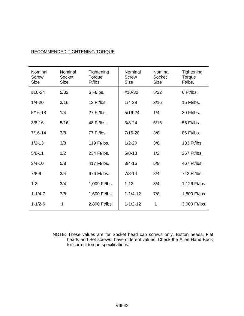
RECOMMENDED TIGHTENING TORQUE Nominal Nominal Tightening Nominal Nominal Tightening Screw Socket Torque Screw Socket Torque Size Size Ft/lbs. Size Size Ft/lbs. #10-24 5/32 6 Ft/lbs. #10-32 5/32 6 Ft/lbs. 1/4-20 3/16 13 Ft/lbs. 1/4-28 3/16 15 Ft/lbs. 5/16-18 1/4 27 Ft/lbs. 5/16-24 1/4 30 Ft/lbs. 3/8-16 5/16 48 Ft/lbs. 3/8-24 5/16 55 Ft/lbs. 7/16-14 3/8 77 Ft/lbs. 7/16-20 3/8 86 Ft/lbs. 1/2-13 3/8 119 Ft/lbs. 1/2-20 3/8 133 Ft/lbs. 5/8-11 1/2 234 Ft/lbs. 5/8-18 1/2 267 Ft/lbs. 3/4-10 5/8 417 Ft/lbs. 3/4-16 5/8 467 Ft/lbs. 7/8-9 3/4 676 Ft/lbs. 7/8-14 3/4 742 Ft/lbs. 1-8 3/4 1,009 Ft/lbs. 1-12 3/4 1,126 Ft/lbs. 1-1/4-7 7/8 1,600 Ft/lbs. 1-1/4-12 7/8 1,800 Ft/lbs. 1-1/2-6 1 2,800 Ft/lbs. 1-1/2-12 1 3,000 Ft/lbs.
NOTE: These values are for Socket head cap screws only. Button heads, Flat heads and Set screws have different values. Check the Allen Hand Book for correct torque specifications.
VIII-42