operating and installation instructions n 816 av.12.29 dc-b
TRANSCRIPT

KNF 121533-121536 09/19 Translation of original Operating and Installation Instructions, english Keep for future use!
Double Diaphragm Pumps
N 86 AN.12.29 DC-B
N 86 AP.12.29 DC-B
Operating and Installation Instructions
Read and observe these Operating and Installation Instructions!
N 816 AV.12.29 DC-B
N 838 AN.12.29 DC-B
N 838 AP.12.29 DC-B
Contents Page
1. About this document ................................................................. 2 2. Use ........................................................................................... 3 3. Safety ....................................................................................... 4 4. Technical Data.......................................................................... 6 5. Design and function ................................................................ 10 6. Installation and connection ..................................................... 12 7. Operation ................................................................................ 21 8. Servicing ................................................................................. 28 9. Troubleshooting ...................................................................... 36 10. Spare parts and accessories .................................................. 39 11. Returns ................................................................................... 41
KNF Neuberger GmbH Alter Weg 3 D-79112 Freiburg
Germany
Phone +49-(0)7664-5909-0 Fax +49-(0)7664-5909-99
E-mail: [email protected] www.knf.de

About this document Diaphragm Pumps N 86.12, N 816.12 and N 838.12
2 Translation of original Operating and Installation Instructions, english, KNF 121533-121536 09/19
1. About this document
1.1. Using the Operating and Installation Instruc-tions
The Operating and Installation Instructions are part of the pump.
Pass on the Operating and Installation Instructions to the next
owner.
Customer-specific project pumps (pump models which begin with
"PJ" or "PM") may differ from the Operating and Installation In-
structions.
For project pumps, also observe the agreed upon specifica-
tions.
1.2. Symbols and markings
Warning
WARNING
A danger warning is located here. Possible consequences of a failure to observe the
warning are specified here. The signal word, e.g.
Warning, indicates the danger level. Measures for avoiding the danger and its conse-
quences are specified here.
Danger levels
Signal word Meaning Consequences if not observed
DANGER warns of immedi-ate danger
Death or serious injuries and/or serious damage are the consequence.
WARNING warns of possible danger
Death or serious injuries and/or serious damage are possible.
CAUTION warns of a possibly dangerous situa-tion
Minor injuries or damage are possible.
Tab. 1
Other information and symbols
An activity to be carried out (a step) is specified here.
1. The first step of an activity to be carried out is specified here.
Additional, consecutively numbered steps follow.
This symbol refers to important information.
Project pumps
Diaphragm Pumps N 86.12, N 816.12 and N 838.12 Use
Translation of original Operating and Installation Instructions, english, KNF 121533-121536 09/19 3
2. Use
2.1. Proper use
The pumps are exclusively intended for transferring gases and
vapors.
Owner's responsibility
Only install and operate the pumps under the operating parameters
and conditions described in Chapter 4, Technical data.
Only complete pumps may be taken into service.
Make sure that the installation location is dry and the pump is
protected against rain, splash, hose and drip water.
Before using a medium, check whether the medium can be trans-
ferred danger-free in the specific application case.
Before using a medium, check the compatibility of the materials of
the pump head, diaphragm and valves with the medium.
Depending on the medium being pumped, a rupture of the working
diaphragm may produce a potentially dangerous mixture when the
medium mixes with the air in the innerspace between the working
diaphragm and the safety diaphragm.
KNF recommends monitoring pressure and flow rate of the
pneumatic system in which the pump is integrated.
If pressure or flow rate change without apparent reason,
immediately switch off the pump and check for damages.
Immediately stop the pump if the working diaphragm rup-
tures. The working diaphragm and the safety diaphragm
must be replaced before continuing with operation (see
chapter 8, Maintenance).
Only transfer gases which remain stable under the pressures and
temperatures occurring in the pump.
2.2. Improper use
The pumps may not be operated in an explosive atmosphere.
The pumps are not suitable for transferring dusts.
The pumps are not suitable for transferring liquids.
The pumps are not suitable for aggressive media. For aggressive
media there are other pumps in the KNF product program – please
ask us for detail.
Pumps designed to create either a vacuum or an overpressure
must not be used for these two purposes simultaneously.
An overpressure must not be applied to the suction side of the
pump.
Operating parameters and
conditions
Requirements for
transferred medium
Safety Diaphragm Pumps N 86.12, N 816.12 and N 838.12
4 Translation of original Operating and Installation Instructions, english, KNF 121533-121536 09/19
3. Safety
Note the safety precautions in sections 6. Installation and
connection, and 7. Operation. The pumps are built according to the generally recognized rules of
technology and in accordance with the occupational safety and
accident prevention regulations. Nevertheless, dangers can result
during their use which lead to injuries to the user or others, or to
damage to the pump or other property.
Only use the pumps in proper technical condition and in accord-
ance with their intended use in a safety and danger-conscious
manner while observing the Operating and Installation Instructions.
Make sure that only trained and instructed personnel or specially
trained personnel work on the pumps. This especially applies to
assembly, connection and servicing work.
Make sure that the personnel has read and understood the Operat-
ing and Installation Instructions, and in particular the "Safety"
chapter.
Observe the accident prevention and safety regulations when
performing any work on the pump and during operation.
When transferring dangerous media, observe the safety regula-
tions when handling these media.
Be aware that the pumps are not designed to be explosion-proof.
Make sure the temperature of the medium is always sufficiently
below the ignition temperature of the medium, to avoid ignition or
explosion. This also applies for unusual operational situations.
Note that the temperature of the medium increases when the pump
compresses the medium.
Hence, make sure the temperature of the medium is sufficiently
below the ignition temperature of the medium, even when it is
compressed to the maximum permissible operating pressure of the
pump. The maximum permissible operating pressure of the pump
is stated in the technical specifications (chapter 4).
If necessary, consider any external sources of energy, such as
radiation, that may add heat to the medium.
In case of doubt, consult the KNF customer service.
Store all replacement parts in a protected manner and dispose of
them properly in accordance with the applicable environmental
protection regulations. Observe the respective national and inter-
national regulations. This especially applies to parts contaminated
with toxic substances.
For the purposes of the Machinery Directive 2006/42/EC, pumps
are “partly completed machinery,” and are therefore to be regarded
as not ready for use. Partly completed machinery may not be
commissioned until such time as it has been determined that the
machine in which the partly completed machinery is to be
assembled is in conformity with the provisions of the Machinery
Directive 2006/42/EC. The following essential requirements of
Personnel
Working in a safety-
conscious manner
Handling dangerous media
Handling combustible media
Environmental protection
EC Directives / Standards

Diaphragm Pumps N 86.12, N 816.12 and N 838.12 Safety
Translation of original Operating and Installation Instructions, english, KNF 121533-121536 09/19 5
Annex I of Directive 2006/42/EC (general principles) are applied
and observed:
− General Principles No. 1
− No. 1.1.2. / 1.1.3. / 1.3.1. / 1.3.3. / 1.3.4. / 1.4.1. / 1.5.8 /
1.5.9. / 1.7.4. / 1.7.4.1. / 1.7.4.3.
As these partly completed machinery are OEM-models the power
supplies and the equipment for disconnecting and switching-off the
partly completed machinery respectively have to be considered
when mounting as well as over-current and overload protective
gear.
In addition a protection against mechanical parts in motion and hot
parts, if existing, has to be provided when mounting.
The pumps conform to the Directive 2011/65/EU.
The following harmonized standards have been used:
N 86 AN.12.29 DC-B
N 86 AP.12.29 DC-B
N 816 AV.12.29 DC-B N 838 AN.12.29 DC-B
N 838 AP.12.29 DC-B
DIN EN 50581 DIN EN 50581 DIN EN 50581
DIN EN 55014-1/2 DIN EN 55014-1/2 DIN EN 61000-6-2/3
DIN EN 61000-6-2/3 Tab. 2
Only have repairs to the pumps carried out by the KNF Customer
Service responsible.
Use only genuine parts from KNF for servicing work.
Customer service and
repairs

Technical Data Diaphragm Pumps N 86.12, N 816.12 and N 838.12
6 Translation of original Operating and Installation Instructions, english, KNF 121533-121536 09/19
4. Technical Data
Pump materials
N 86 AN.12.29 DC-B
N 838 AN.12.29 DC-B
Assembly Material
Ribbed plate, intermediate plate, intermediate ring
Aluminium
Working diaphragm NBR
Safety diaphragm NBR
Valve plate/sealing NBR
Diaphragm parts made of steel Steel Tab. 3
N 86 AP.12.29 DC-B
N 838 AP.12.29 DC-B
Assembly Material
Ribbed plate, intermediate plate, intermediate ring
Anodized aluminium
Working diaphragm EPDM
Safety diaphragm NBR
Valve plate/sealing EPDM
Diaphragm parts made of steel Steel Tab. 4
N 816 AV.12.29 DC-B
Assembly Material
Ribbed plate, intermediate plate, intermediate ring
Anodized aluminium
Working diaphragm FPM
Safety diaphragm FPM
Valve plates/sealings FPM
Diaphragm parts made of steel Steel Tab. 5
Pneumatic values
N 86 AN.12.29 DC-B
N 86 AP.12.29 DC-B
Parameter Value
Max. permissible operating pressure [bar g] 1.0
Ultimate vacuum [mbar abs.] 250
Flow rate at atm. pressure [l/min]* 4.5 Tab. 6 *Liters in standard state (1,013 mbar)

Diaphragm Pumps N 86.12, N 816.12 and N 838.12 Technical Data
Translation of original Operating and Installation Instructions, english, KNF 121533-121536 09/19 7
N 816 AV.12.29 DC-B
Parameter Value
Max. permissible operating pressure [bar g] 0.6
Ultimate vacuum [mbar abs.] 250
Flow rate at atm. pressure [l/min]* 11 Tab. 7 *Liters in standard state (1,013 mbar)
N 838 AN.12.29 DC-B
N 838 AP.12.29 DC-B
Parameter Value
Max. permissible operating pressure [bar g] 0.6
Ultimate vacuum [mbar abs.] 200
Flow rate at atm. pressure [l/min]* 25
Flow rate at atm. pressure and 0.1 V control voltage [l/min]*
4.9
Tab. 8 *Liters in standard state (1,013 mbar)
Pneumatic Connection
Parameter Value
N 86 A_.12.29 DC-B Thread size G 1/8
N 816 AV.12.29 DC-B Thread size G 1/8
N 838 A_.12.29 DC-B Thread size G 1/8
Tab. 9
Electrical data
N 86 AN.12.29 DC-B N 86 AP.12.29 DC-B
N 816 AV.12.29 DC-B
Parameter Value
Electrical data See type plate Tab. 10
N 838 AN.12.29 DC-B
N 838 AP.12.29 DC-B
Parameter Value
Motor type Brushless DC motor
Voltage [V] 24
Control voltage (only .29 ver-sion) [V]
0.1…5*
Max. operating current [A] - for p > patm. - for p < patm.
1.90 1.80
Starting current The starting current can be up to 50 % above the maximum operating current.
Starting ramp [ms] 800
Technical Data Diaphragm Pumps N 86.12, N 816.12 and N 838.12
8 Translation of original Operating and Installation Instructions, english, KNF 121533-121536 09/19
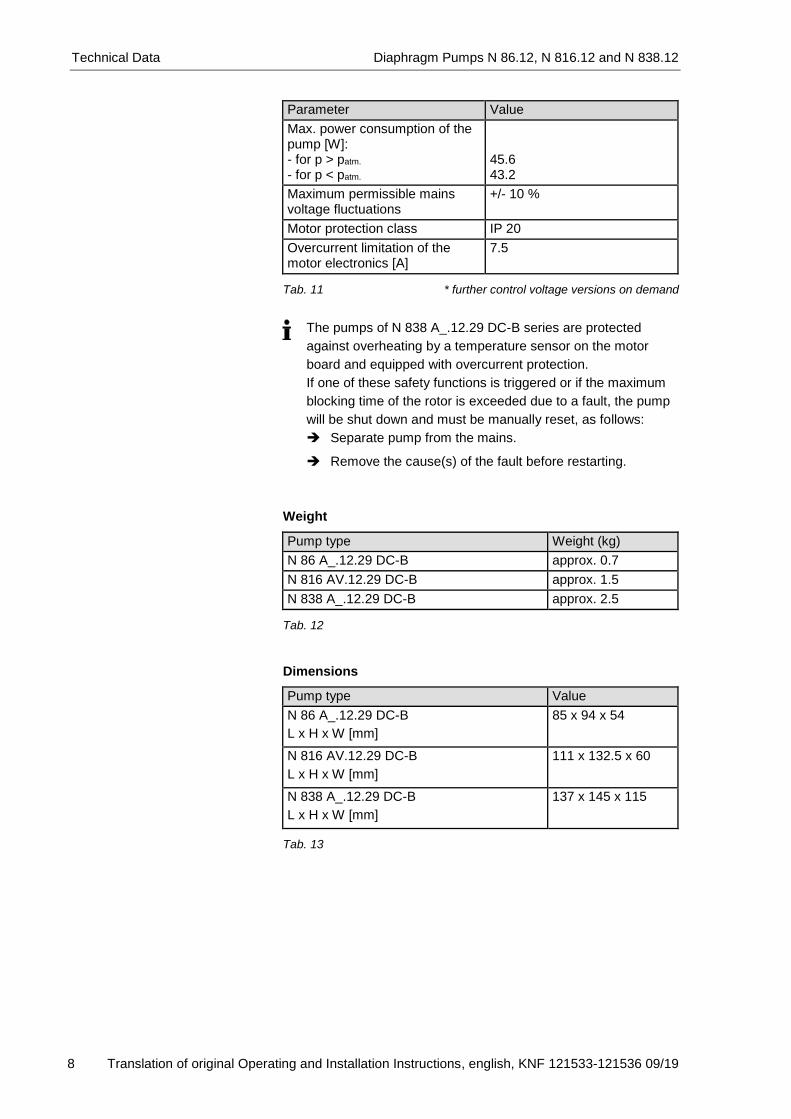
Parameter Value
Max. power consumption of the pump [W]: - for p > patm.
- for p < patm.
45.6 43.2
Maximum permissible mains voltage fluctuations
+/- 10 %
Motor protection class IP 20
Overcurrent limitation of the motor electronics [A]
7.5
Tab. 11 * further control voltage versions on demand
Weight
Pump type Weight (kg)
N 86 A_.12.29 DC-B approx. 0.7
N 816 AV.12.29 DC-B approx. 1.5
N 838 A_.12.29 DC-B approx. 2.5 Tab. 12
Dimensions
Pump type Value
N 86 A_.12.29 DC-B
L x H x W [mm]
85 x 94 x 54
N 816 AV.12.29 DC-B
L x H x W [mm]
111 x 132.5 x 60
N 838 A_.12.29 DC-B
L x H x W [mm]
137 x 145 x 115
Tab. 13
The pumps of N 838 A_.12.29 DC-B series are protected
against overheating by a temperature sensor on the motor
board and equipped with overcurrent protection.
If one of these safety functions is triggered or if the maximum
blocking time of the rotor is exceeded due to a fault, the pump
will be shut down and must be manually reset, as follows:
Separate pump from the mains.
Remove the cause(s) of the fault before restarting.

Diaphragm Pumps N 86.12, N 816.12 and N 838.12 Technical Data
Translation of original Operating and Installation Instructions, english, KNF 121533-121536 09/19 9
Other parameters
Parameter Values
Permissible ambient temperature for pump types N 86 AN.12.29 DC-B and N 838 AN.12.29 DC-B
+ 5 °C to + 50 °C
Permissible ambient temperature for pump types N 86 AP.12.29 DC-B, N 816 AV.12.29 DC-B and N 838 AP.12.29 DC-B
+ 5 °C to + 60 °C
Permissible media temperature + 5 °C to + 40 °C
Gas-tightness* of pump head (leak rate)
< 6 x 10⁻⁴ mbar l/s**
Maximum permissible ambient rela-tive humidity
80 % for temperatures up to 31 °C, decreasing linearly to 50 % at 40 °C
Max. altitude of site [m above sea level]
2000
Tab. 14
* Perform a leak test in order to ensure gastightness after opening the pump head or after exchanging diaphragms and valve plates/sealings.
** Values valid for helium leak tests

Design and function Diaphragm Pumps N 86.12, N 816.12 and N 838.12
10 Translation of original Operating and Installation Instructions, english, KNF 121533-121536 09/19
5. Design and function
Design N 86 A_.12.29 DC-B
1 Pump head 2 Motor 3 Base plate 4 Pneumatic inlet 5 Pneumatic outlet
Fig. 1: Double diaphragm pump N 86 AN.12.29 DC-B
Design N 816 AV.12.29 DC-B
1 Pump head 2 Pneumatic inlet 3 Pneumatic outlet 4 Motor 5 Base plate
Fig. 2: Double diaphragm pump N 816 AV.12.29 DC-B
Design N 838 A_.12.29 DC-B
1 Pump head 2 Pneumatic outlet 3 Pneumatic inlet 4 Electronics cover 5 Voltage supply 6 Control connections 7 Footplate 8 Ground connection 9 Motor
Fig. 3: Double diaphragm pump N 838 AN.12.29 DC-B

Diaphragm Pumps N 86.12, N 816.12 and N 838.12 Design and function
Translation of original Operating and Installation Instructions, english, KNF 121533-121536 09/19 11
Function Double diaphragm pumps
1 Outlet valve 2 Inlet valve 3 Transfer chamber 4 Working diaphragm 5 Innerspace 6 Safety diaphragm 7 Eccentric 8 Connecting rod 9 Pump drive
Fig. 4: Pump head
Double diaphragm pumps transfer, compress (depending on pump
version) and evacuate gases and vapors.
The elastic working diaphragm (4) is moved up and down by the
eccentric (7) and the connecting rod (8). In the downward stroke it
aspirates the gas to be transferred via the inlet valve (2). In the
upward stroke, the working diaphragm presses the medium out of
the pump head via the outlet valve (1). The transfer chamber (3) is
hermetically separated from the pump drive (9) by the working
diaphragm.
A second diaphragm (safety diaphragm (6)) is located underneath
the working diaphragm. This second diaphragm is under less
mechanical stress when the pump is operating. lf gas should leak
at the working diaphragm, it will still remain inside the pump space.

Installation and connection Diaphragm Pumps N 86.12, N 816.12 and N 838.12
12 Translation of original Operating and Installation Instructions, english, KNF 121533-121536 09/19
6. Installation and connection
Only install and operate the pumps under the operating parameters
and conditions described in Chapter 4, Technical data.
Observe the safety precautions (see Chapter 3).
6.1. Installation of the pump
Before installation, store the pump at the installation location to
bring it up to ambient temperature.
See fig. 5, p. 13 (pump series N 86 A_.12.29 DC-B), fig. 6,
p. 13 (pump series N 816 AV.12.29 DC-B) and fig. 7, p. 14
(pump series N and N 838 A_.12.29 DC-B) for the mounting
dimensions.
When installing the pump, ensure that no flammable objects or
objects subject to thermal deformation are located in the im-
mediate vicinity of hot pump parts (head, motor).
The pump may be installed in any position. Use metal screws
to fasten the pump at the indicated attachment points.
When installing the pump, ensure an adequate flow of cooling
air.
Fasten the connection cables so that:
the cables do not contact moving parts
the cables will not chafe or be damaged on sharp edges or
corners
no pulling or pushing forces are exerted on the cable’s
connection points (strain relief).
Take protective measures against touching and foreign objects
which could enter the pump.
Make sure that the installation location is dry and the pump is
protected against rain, splash, hose and drip water.
The IP protection class of the pump motor is indicated on the
type plate. Install the pump at the highest point in the system to prevent
condensate from collecting in the pump head.
Protect the pump from dust.
Protect the pump from exposure to fats and oils.
Protect the pump from vibrations and jolts.
Mounting dimensions
Immediate environment
Installation position
Cooling air flow
Attach connection cables
Protection against touching and
foreign objects
Installation location

Diaphragm Pumps N 86.12, N 816.12 and N 838.12 Installation and connection
Translation of original Operating and Installation Instructions, english, KNF 121533-121536 09/19 13
Fig. 5: Mounting dimensions pump series N 86 A_.12.29 DC-B
(All dimensional tolerances conform to DIN ISO 2768-1,
Tolerance Class V)
Fig. 6: Mounting dimensions pump series N 816 AV.12.29 DC-B
(All dimensional tolerances conform to DIN ISO 2768-1,
Tolerance Class V)

Installation and connection Diaphragm Pumps N 86.12, N 816.12 and N 838.12
14 Translation of original Operating and Installation Instructions, english, KNF 121533-121536 09/19
Fig. 7: Mounting dimensions pump series N 838 A_.12.29 DC-B
(All dimensional tolerances conform to DIN ISO 2768-1,
Tolerance Class V)

Diaphragm Pumps N 86.12, N 816.12 and N 838.12 Installation and connection
Translation of original Operating and Installation Instructions, english, KNF 121533-121536 09/19 15
6.2. Electrical connection Only have the pump connected by an authorized specialist.
Only have the pump connected when the power supply is
disconnected.
When connecting the device to a power source, the relevant
standards, directives, regulations, and technical standards
must be observed.
In the electrical installation, arrangements (complying with EN
60335-1) must be made for disconnecting the pump motor
from the electrical supply.
It is recommended that an additional “Emergency Stop” switch
is installed.
The pump must be installed so that contact with live parts is
impossible.
Connecting pump
1. Compare the supply data with the data on the motor-plate. For
operating current see type plate.
The voltage must not vary by more than + 10% and - 10% from
that shown on the type-plate. Refer to the following tables for
limit values when setting speed and flow rate through the
supply voltage.
2. Connect motor cable
Observe proper polarity. Incorrect polarity will damage the
electronics!
For N 86A_.12.29 DC-B:
Motors marked with a “K” on the type plate of the motor have
inverse-polarity protection.
For N 838 A_.12.29 DC-B:
The supply wires have inverse-polarity protection on the motor
board for this purpose, while the control-voltage wires do not
have this protection function.
For N 838 A_.12.29 DC-B:
Control voltage may only be applied if the motor controller is
supplied with operating voltage. Otherwise damages can occur
on the motor controller.

Installation and connection Diaphragm Pumps N 86.12, N 816.12 and N 838.12
16 Translation of original Operating and Installation Instructions, english, KNF 121533-121536 09/19
Pump series N 86 A_.12.29 DC-B
Motor 2-Litzen
(optional) 4- Litzen
(standard)
Nennspannung / Nominal voltage [V] 12 24 12 24
Spannungsbereich / Voltage range [V] 10…15 14…28 10…15 14…28
Elektrische Anschlüsse / Electrical connection
Litzenbelegung / lead assignment
Funktion / function Litzenfarbe lead color
Signalname signal name
Größe / Size
+ Speisespannung + Supply voltage
rot / red + VS AWG 24 UL 1007
AWG 24 UL 1007
- Speisespannung - Ground (0V)
blau oder schwarz blue or black
- VS / GND AWG 24 UL 1007
AWG 24 UL 1007
Drehzahlregelung Eingangssignal Speed control voltage input signal
weiß / white VCtrl - AWG 24 UL 1007
Frequenzausgang Eingangssignal Frequency generator output
grün / green FGOut - AWG 24 UL 1007
DC oder PWM Steuereingang VCtrl / DC or PWM input VCtrl
Steuerspannungsbereich DC Control voltage range DC
[V] 1.0…4.7
Max. Eingangsspannung Max. input voltage
[V] ±30
Eingangswiderstand (VCtrl < 5V) Input resistance (VCtrl < 5V)
[kΩ] typ. 10
Schwellenspannung Treshold voltage
[V] 1.0±0.2
Drehzahl / Spannung Konstante Speed / VCtrl relation (at no load)
[rpm/V] typ. 950±250
Nominal PWM Signalamplitude Nominal PWM signal amplitude
5
PWM Signal Minimalwert PWM signal „low“ level
[V] max 0.1
PWM Frequenzbereich PWM frequence range
[kHz] >6
PWM Anteil Schwellwert (VCtrl 5V ohne Last) PWM duty cycle treshold (VCtrl 5V no load)
[%] ~12
PWM Anteil volle Drehzahl (VCtrl 5V ohne Last) PWM duty cycle full speed (VCtrl 5V no load) [%] ~70
FG Frequenzausgang / FG frequency output
FG Impulse pro Umdrehung FG pulses per revolution
6
Impulsdauer „high“ Pulse length „high“
[%] 33
Ausgangsserienwiderstand Output series resistance
[kΩ] 3.9
Ausgangspegel „high“ (lout < 0.1mA) Output level „high“(lout < 0.1mA)
[V] 4.2…5.4
Ausgangspegel „low“ (lout < 0.1mA) Output level „low“(lout < 0.1mA)
[V] max 0.5
Tab. 15: Connection plan motor electronics for pump series
N 86 A_.12.29 DC-B

Diaphragm Pumps N 86.12, N 816.12 and N 838.12 Installation and connection
Translation of original Operating and Installation Instructions, english, KNF 121533-121536 09/19 17
To ensure interference suppression according to DIN EN 55014-1
+ A1 and DIN EN 61000-6-3 + A1 pump types equipped with the
brushless DC motor (DC-B) must be equipped with a supplemental
electronic circuit.
The supplemental circuit must be structured according to the
following electrical diagram with the capacitor C1:
C1 Capacitor 1 (470 µF, 35V)
M Motor * Capacitor in the motor
(100nF, 50V)
Fig. 8: Supplemental electronic circuit N 86 K_DC-B with “K” marking on
the type plate
Pump series N 816 AV.12.29 DC-B
4-lead motor (standard version)
Colour of cable Functions
Red V+ 24 V version: 14–30 V
Black Ground
White Speed input Vctrl 0–5 V DC
Green Frequence output (36 pulses per revolution)
_ _ _ Shield Tab. 16
2- lead motor (optional version)
Colour of cable Functions
Red V+ 24 V version: 14–30 V
Black Ground Tab. 17
To ensure interference suppression according to EN 55014-1:1993
+ A1:1997 Emissions and EN 55014-2 (interference immunity)
(product family standard) pumps of the series N 816 AV.12 DC-B
must be equipped with a supplemental circuit. The supplemental
circuit must be installed as close as possible to the motor.
The supplemental circuit must be structured according to the
following electrical diagram and the components defined therein in
order to achieve the required level of suppresion (Fig. 9).
EMC-compatible
Installation
Supplemental circuit

Installation and connection Diaphragm Pumps N 86.12, N 816.12 and N 838.12
18 Translation of original Operating and Installation Instructions, english, KNF 121533-121536 09/19
Fig. 9: Supplemental electronic circuit for pumps N 816 AV.12.29 DC-B
C1: Capacitor 1000 μF

Diaphragm Pumps N 86.12, N 816.12 and N 838.12 Installation and connection
Translation of original Operating and Installation Instructions, english, KNF 121533-121536 09/19 19
Pump series N 838 A_.12.29 DC-B
Pin Nr.
Pin No.
Farbkodierung
Color coding
Benennung
Description
Elektrische Eigenschaft
Electrical characteristic
1 schwarz
black
DC Spannungsquelle
DC power supply
U0-DC: 5±0.2V
I0: max. 170mA
2 weiß
white
Eingang Steuerspannung
Control voltage input UIN-DC: 0…5V (PIN-MAX: ≤5mW)
fPWM-IN: 100Hz±50Hz
duty cycle: 0…100%
RIN:≥12.2kΩ @1kHz 3* grau
grey
Masse
Ground
4 lila
purple
Ausgang Fehlermeldung
Error signal output UERROR-0-DC: ≤0.6V / UERROR-1-DC: ≥4.5V…U0-DC
5* blau
blue
Masse
Ground UON-DC: ≤0.9V
UOFF-DC: ≥4.2V…U0-DC 6
grün
green
Eingang Remote EIN/AUS
Input Remote ON/OFF
7 gelb
yellow
Ausgang Drehzahlsignal
Speed signal output PWM-OUT
fPWM-OUT: 50Hz
UPWMF-OUT: U0-DC
duty cycle: 0…100%
FREQ-OUT
fFREQ-OUT: n
1 pulse / revolution
UFREQ-OUT: U0-DC 8* orange
orange
Masse
Ground
Zulässige Spannung an den Steuereingängen
allowable voltage at control inputs UDC: max. 5.5V
Zulässige Strombelastbarkeit an den Steuerausgängen
allowable ampacity at control outputs I: max. 10mA
Fig. 10: Connection plan motor electronics
* Ground Pin 3, 5 and 8 are connected with each other
If Pin 1 is simultaneously used as control voltage specification
for Pin 2, please contact the KNF customer services (see last
page for telephone number).

Installation and connection Diaphragm Pumps N 86.12, N 816.12 and N 838.12
20 Translation of original Operating and Installation Instructions, english, KNF 121533-121536 09/19
6.3. Pneumatic connection
Only connect components to the pump which are designed for
the pneumatic data of the pump (see Chapter 4, Technical da-
ta).
If the pump is used as a vacuum pump, safely discharge the
pump exhaust at the pump’s pneumatic outlet.
Connecting pump
A marking on the pump head shows the direction of flow.
1. Remove the protective plugs from the hose connection
threads.
2. Connect the suction line and pressure line.
3. Lay the suction and pressure line at a downward angle to
prevent condensate from running into the pump.
6.4. Install monitoring device
WARNING
Danger of dangerous gas mixtures during operation
of the pump if the working diaphragm ruptures Depending on the medium being pumped, a rupture
of the working diaphragm may produce a potentially
dangerous mixture when the medium mixes with the
air in the innerspace between the working diaphragm
and the safety diaphragm.
KNF recommends monitoring pressure and flow
rate of the pneumatic system in which the pump
is integrated. If pressure or flow rate change without apparent
reason, immediately switch off the pump and
check for damages.
Immediately stop the pump if the working dia-
phragm ruptures. The working diaphragm and
the safety diaphragm must be replaced before
continuing with operation (see chapter 8,
Maintenance).
Connected
components
Pump exhaust

Diaphragm Pumps N 86.12, N 816.12 and N 838.12 Operation
Translation of original Operating and Installation Instructions, english, KNF 121533-121536 09/19 21
7. Operation
7.1. General
Only operate the pumps under the operating parameters and
conditions described in Chapter 4, Technical data.
Make sure the pumps are used properly (see section 2.1).
Make sure the pumps are not used improperly (see section
2.2).
Observe the safety precautions (see Chapter 3).
The pumps are intended for installation. Before putting them
into service it must be established that machinery or equipment
in which they are installed meets the relevant regulations.
WARNING
Hazard of the pump head bursting due to excessive
pressure increase Do not exceed max. permissible operating
pressure (see Chapter 4, Technical data).
Monitor pressure during operation.
If the pressure exceeds the maximum permissi-
ble operating pressure, immediately switch off
pump and eliminate fault (see Chapter 9. Trou-
bleshooting). Only throttle or regulate the air or gas quantity in
the suction line to prevent the maximum permis-
sible operating pressure from being exceeded. If the air or gas quantity in the pressure line is
throttled or regulated, make sure that the maxi-
mum permissible operating pressure is not ex-
ceeded.
Ensure that the pump outlet is not closed or
constricted.
Excessive pressure (with all of the related hazards) can be
prevented by placing a bypass line with a pressure-relief valve
between the pressure and suctions sides of the pump. For
further information, contact our technical adviser (see last page
for telephone number).
Operation Diaphragm Pumps N 86.12, N 816.12 and N 838.12
22 Translation of original Operating and Installation Instructions, english, KNF 121533-121536 09/19
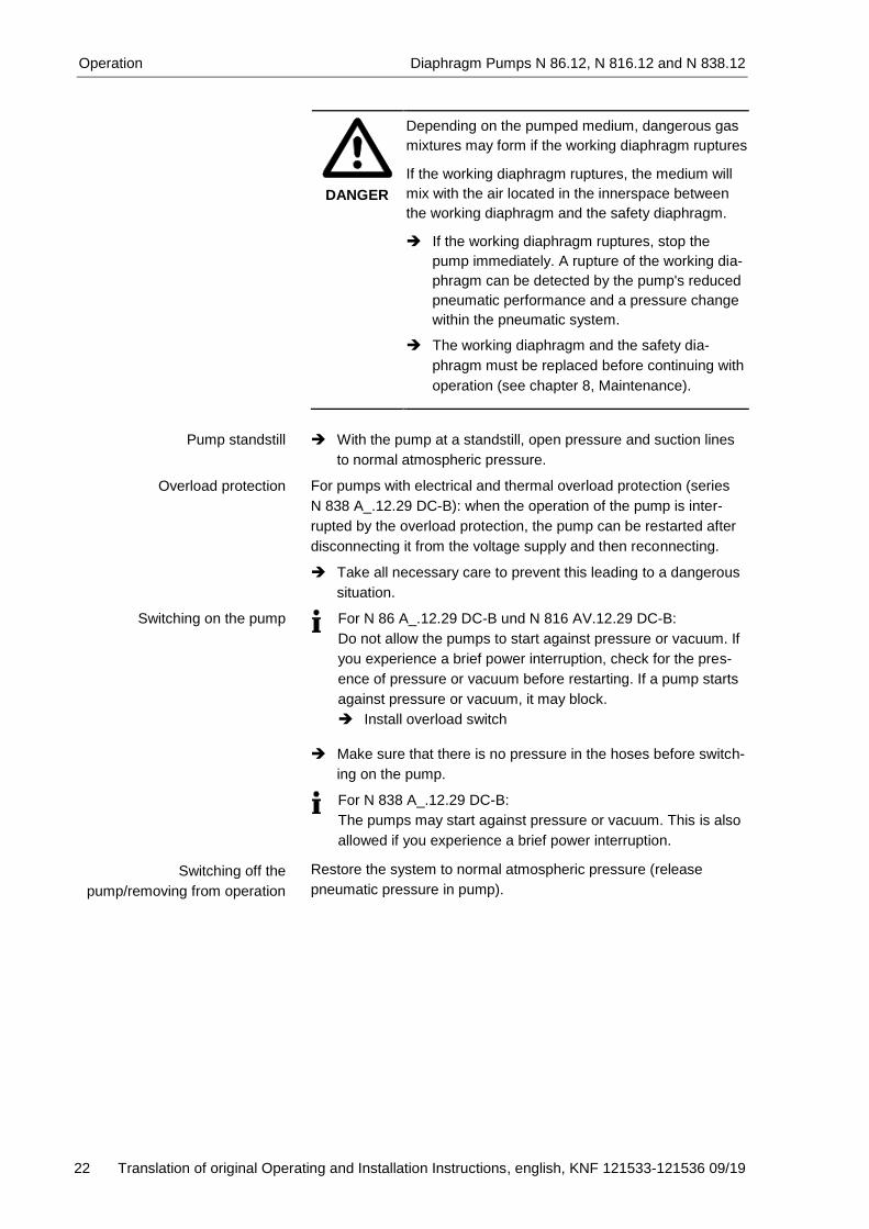
DANGER
Depending on the pumped medium, dangerous gas
mixtures may form if the working diaphragm ruptures
If the working diaphragm ruptures, the medium will
mix with the air located in the innerspace between
the working diaphragm and the safety diaphragm.
If the working diaphragm ruptures, stop the
pump immediately. A rupture of the working dia-
phragm can be detected by the pump's reduced
pneumatic performance and a pressure change
within the pneumatic system.
The working diaphragm and the safety dia-
phragm must be replaced before continuing with
operation (see chapter 8, Maintenance).
With the pump at a standstill, open pressure and suction lines
to normal atmospheric pressure.
For pumps with electrical and thermal overload protection (series
N 838 A_.12.29 DC-B): when the operation of the pump is inter-
rupted by the overload protection, the pump can be restarted after
disconnecting it from the voltage supply and then reconnecting.
Take all necessary care to prevent this leading to a dangerous
situation.
For N 86 A_.12.29 DC-B und N 816 AV.12.29 DC-B:
Do not allow the pumps to start against pressure or vacuum. If
you experience a brief power interruption, check for the pres-
ence of pressure or vacuum before restarting. If a pump starts
against pressure or vacuum, it may block.
Install overload switch
Make sure that there is no pressure in the hoses before switch-
ing on the pump.
For N 838 A_.12.29 DC-B:
The pumps may start against pressure or vacuum. This is also
allowed if you experience a brief power interruption. Restore the system to normal atmospheric pressure (release
pneumatic pressure in pump).
Pump standstill
Overload protection
Switching on the pump
Switching off the
pump/removing from operation
Diaphragm Pumps N 86.12, N 816.12 and N 838.12 Operation
Translation of original Operating and Installation Instructions, english, KNF 121533-121536 09/19 23
7.2. Control functions
7.2.1. Speed control
Pump series N 86 A_.12.29 DC-B
The pumps’ motor speed and therefore their flow rates can be set
and at some pump versions controlled (see Tab.15).
Pump series N 816 AV.12.29 DC-B
The pumps’ motor speed and therefore their flow rates can be set
and at some pump versions controlled (see Tab. 18).
Pump types Speed
N 816 AV.12.29 DC-B with 4-lead motor (standard version)
- Control through input signal 0 to 5 V DC
N 816 AV.12.29 DC-B with 2-lead motor (optional version)
- Regulate through supply voltage
Tab. 18
Pump series N 838 A_.12.29 DC-B
The motor drives the pump at a changeable speed between nmin
and nmax. Speed is specified via the control voltage.
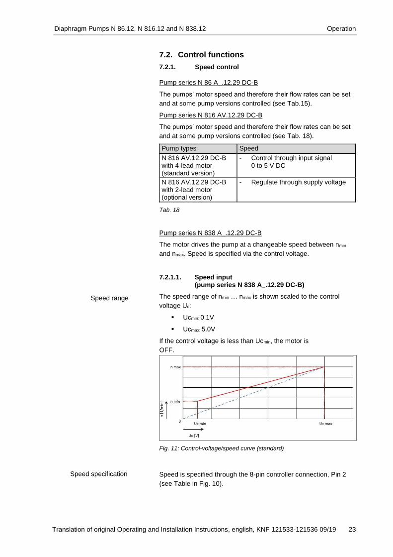
7.2.1.1. Speed input (pump series N 838 A_.12.29 DC-B)
The speed range of nmin … nmax is shown scaled to the control
voltage Uc:
Ucmin: 0.1V
Ucmax: 5.0V
If the control voltage is less than Ucmin, the motor is
OFF.
Fig. 11: Control-voltage/speed curve (standard)
Speed is specified through the 8-pin controller connection, Pin 2
(see Table in Fig. 10).
Speed range
Speed specification

Operation Diaphragm Pumps N 86.12, N 816.12 and N 838.12
24 Translation of original Operating and Installation Instructions, english, KNF 121533-121536 09/19
Optional settings for control voltage input
The following additional settings can be made at the factory upon
request:
Modify control voltage values Ucmin and Ucmax
If the control voltage is less than Ucmin, the motor will be
ON.
Fig. 12: Scaled control-voltage/speed curve (optional)
7.2.1.2. Speed output
(pump series N 838 A_.12.29 DC-B)
Speed is outputted through the 8-pin controller connection (Pin 7,
see Table in Fig. 10).
The motor controller generates speed-synchronized pulse-width
modulation (see Fig. 13).
Fig. 13: Analog speed output (standard)
Optional speed output
The motor controller generates a speed-synchronized right-angle
frequency with 5V TTL level (see Fig. 14).
Fig. 14: Digital speed output (optional)
Speed output

Diaphragm Pumps N 86.12, N 816.12 and N 838.12 Operation
Translation of original Operating and Installation Instructions, english, KNF 121533-121536 09/19 25
7.2.2. Remote ON/OFF (pumpe series N 838 A_.12.29 DC-B)
Remote ON/OFF is through an 8-pin controller connection (Pin 6,
see Fig. 10).
To start the motor, Pin 6 must be bridged to the ground of the
controller connection.
7.2.3. External activation (pump series N 838 A_.12.29 DC-B, optional)
If desired, the pump motor can be activated externally. This re-
quires a special setting at the factory (see final page for contact
address).
External activation is through the 6-pin communication connection
(see Fig. 10 above).
Connector type: Micro-Match Female Top Entry
Part no.: 7-215079-6
When the motor is activated externally, the control inputs are
inactive.
Connection communication plug (see Fig. 10 top)
PIN 1 – do not connect
PIN 2 - do not connect
PIN 3 – GND
PIN 4 – 5V (max. 50 mA)
PIN 5 – TX MBLC
PIN 6 - RX MBLC
Motor connection options – external control unit
Fig. 15: External activation options (optional)
The following motor functions can be controlled:
Motor remote ON/OFF
In the factory condition, the motor is OFF when operating
voltage is applied. However, as an option the motor can be
ON when operating voltage is applied.
Motor speed
Setting motor speed within speed limits nmin and nmax.
Read-out of the following process parameters:
- Actual/Nominal motor speed
Remote ON/OFF
External activation
Operation Diaphragm Pumps N 86.12, N 816.12 and N 838.12
26 Translation of original Operating and Installation Instructions, english, KNF 121533-121536 09/19
- Control limit of motor speed
- Operating current of the motor
- Temperature of the motor controller
- Fault status
- Software version number
The connection between the PC and motor controller can be
operated as an RS-232 interface. Accordingly, in the operating
system it is managed as an additional COM connection and can be
addressed with conventional terminal software.
Interface configuration
Baud rate: 57600 bits/s
Data bits: 8
Parity: none
Stop bits: 1
Flow control: none
Tables 19 to 21 contain the necessary command sets, shown as
ASCII characters. When transmitting, the commands must be
followed by ASCII character <CR> (carriage return, decimal value
013). The underlined expressions are not characters, but symbols
as explained in table 16.
Parameter Command* Function Reply
Motor dB Start S ; E
dE Stop S ; E
Speed dSnnnn [nnnn = speed value]
Set nominal speed ns ; E
Tab. 19: Control commands
* A pause of at least 25 ms is required after the “dB“ instruction set.
Parameter Command Reply
Actual motor speed;
operating current of the motor;
temperature of the motor controller;
Fault status
pP ni ; ii , ti , ei ; E
Fault status (single value) gP ei ; E
Nominal motor speed gS ns ; E
Minimum possible motor speed
gSl nl ; E
Maximum possible motor speed
gSh nh ; E
Software version number iV V ; E Tab. 20: Read commands
Interface protocol
Diaphragm Pumps N 86.12, N 816.12 and N 838.12 Operation
Translation of original Operating and Installation Instructions, english, KNF 121533-121536 09/19 27
Symbol Interpretation Meaning
E Announcement of completion
0 command cannot be completed
1 command completed
? command unclear
S Status message For service only
V Version number e.g. 01.018
ni Actual motor speed Value [min-1]
ns Nominal motor speed Value [min-1]
nl Minimum nominal motor speed
Value [min-1]
nh Maximum nominal motor speed
Value [min-1]
ii operating current of the motor
Value [mA]
ti temperature of the motor controller
Value [°C]
ei Fault status 16 bit value Tab. 21: Symbols
The symbols represent the ASCII codes of sequences of digits any
length. The controller processes input values only as whole num-
bers (integers).
Interface level
See p. 19 for pin assignment of the motor controller’s com-
munication plug.
Tab. 22
Parameter Value
Rx KNF MBLC Low: 0V…0.9V High: 4.2V…5.2V
Tx KNF MBLC Low: 0V…0.6V High: 4.5V…5.2V

Servicing Diaphragm Pumps N 86.12, N 816.12 and N 838.12
28 Translation of original Operating and Installation Instructions, english, KNF 121533-121536 09/19
8. Servicing
8.1. Servicing schedule Component Servicing interval
Pump - Regular inspection for external dam-age or leaks
Working diaphragm, safety diaphragm and valve plates/ sealings
- Replace if pump's pressure or flow rate change without apparent reason
- Replace at the latest, when pump output decreases
Tab. 23
8.2. Cleaning
When cleaning, make sure that no liquids enter the inside of
the housing.
8.2.1. Flushing pump
Flush the pump under atmospheric conditions some minutes
with air (or, if necessary for safety reasons, with an inert gas)
prior to switch-off.
8.2.2. Cleaning pump
Motor disconnected from mains and de-energized
WARNING
Health hazard due to dangerous substances
in the pump!
Depending on the substance transferred, caustic
burns or poisoning are possible.
Wear protective clothing if necessary, e.g.
protective gloves.
Clean pump with suitable measures.
CAUTION
Danger of burns from hot pump parts
The pump head or motor may be hot even after the
pump has been shut off.
Allow the pump to cool off after operation.
Only use solvents for cleaning if the head materials cannot be
attacked (check the resistance of the material).
If compressed air is available, blow out the components.
Conditions

Diaphragm Pumps N 86.12, N 816.12 and N 838.12 Servicing
Translation of original Operating and Installation Instructions, english, KNF 121533-121536 09/19 29
8.3. Replacing working diaphragm, safety dia-phragm and valve plates/sealings
Motor disconnected from mains and de-energized
Pump free of dangerous substances
Tubes/pipes removed from pump’s pneumatic inlet and
outlet
WARNING
There is the danger that hazardous gas mixtures will
form and that the pumped media will leak from the
pump while the pump is in operation, if the safety
diaphragm is not replaced at the same time as the
working diaphragm. Always replace the safety diaphragm at the
same time the working diaphragm is replaced.
Always replace the working diaphragm, safety diaphragm and
valve plates/sealings together to maintain the pump perfor-
mance.
WARNING
Health hazard due to dangerous substances
in the pump!
Depending on the substance transferred, caustic
burns or poisoning are possible.
Wear protective clothing if necessary, e.g.
protective gloves.
Clean pump with suitable measures.
Conditions

Servicing Diaphragm Pumps N 86.12, N 816.12 and N 838.12
30 Translation of original Operating and Installation Instructions, english, KNF 121533-121536 09/19
8.3.1. N 86 A_.12.29 DC-B
Spare part* Position** Quantity
Working diaphragm (5) 1
Safety diaphragm (7) 1
Valve plate/sealing (3) 1 Tab. 24 * According to spare parts list, chapter 10
** According to Fig. 16
Quantity Tools/Material
1 Phillips screwdriver No. 1
1 Wrench for safety diaphragm N 86.12*
1 Felt-tip pen Tab. 25 * according to accessories list, chapter 10
Removing pump head
1. Mark the position of ribbed plate (2), intermediate plate (4),
intermediate ring (6) and pump housing relatively to each other
by a drawing line with a felt-tip pen to ensure proper assembly.
2. Remove the ribbed plate:
Set down the ribbed plate carefully to avoid damaging its sealing edge. Unscrew the four screws (1) and remove the ribbed plate (2).
3. Remove the intemediate plate (4).
Set down the intermediate plate carefully to avoid damaging its sealing edge. The working diaphragm (5) is visible.
Replacing working diaphragm and safety diaphragm
1. Lift the working diaphragm (5) by the opposing side edges,
grasp it and unscrew it in the counter-clockwise direction.
2. Remove intermediate ring (6) from pump housing.
3. Unscrew safety diaphragm:
Make sure the diaphragm spacer(s) (8) do not fall into the
pump housing.
Unscrew the safety diaphragm (7) in the counter-clockwise di-
rection by using the wrench for safety diaphragm.
4. Remove the diaphragm spacer(s) (8) from the threaded pin of
the safety diaphragm and keep in a safe place.
5. Carefully clean on the compressor housing the surface which
contacts the safety diaphragm (7) and check it for damage.
6. Push the diaphragm spacer(s) (8) onto the threaded pin of the
new safety diaphragm (7); screw the safety diaphragm clock-
wise onto the connecting rod (connecting piece between drive
shaft and safety diaphragm) and tighten it tight by using the
wrench for safety diaphragm.
7. Clean intermediate ring (6) and check its sealing edges for
damage.
Spare parts
Tools and material
Fig. 16: N 86 A_.12.29 DC-B:
Parts of pump head

Diaphragm Pumps N 86.12, N 816.12 and N 838.12 Servicing
Translation of original Operating and Installation Instructions, english, KNF 121533-121536 09/19 31
8. Place the intermediate ring (6) onto pump housing in accord-
ance with the felt-tip pen marking.
9. Screw the working diaphragm (5) clockwise onto the safety
diaphragm (7) and tighten hand-tight.
Replacing valve plate/sealing
1. Remove the valve plate/sealing (3) from the intermediate
plate (4).
2. Check the intermediate plate (4) and ribbed plate (2) for soiling
and damage. Clean the parts if necessary. Make sure that the
sealing edges of the ribbed plate (2) and intermediate plate (4)
are undamaged.
3. Contact KNF in case of roughness, scratches and corrosion.
Order and replace damaged parts.
4. Insert valve plate/sealing:
Upper and lower side of the valve plate/sealing are identical.
Lay new valve plate/sealing (3) in the valve seat of the inter-
mediate plate (4).
5. Dispose of the old working diaphragm, safety diaphragm and
valve plate/sealing properly.
Mounting pump head
1. Place intermediate plate (4) on the intermediate ring (6) in
accordance with the felt-tip pen marking.
2. Place the ribbed plate (2) on the intermediate plate (4) in
accordance with the felt-tip pen marking.
3. Check the centering of the ribbed plate (2) by moving it slightly
from side to side.
4. Screw in the screws (1) and tighten first only slightly diagonal-
ly, then tight.
Perform a leak test in order to ensure the required gastight-
ness of the pump head after maintenance.

Servicing Diaphragm Pumps N 86.12, N 816.12 and N 838.12
32 Translation of original Operating and Installation Instructions, english, KNF 121533-121536 09/19
8.3.2. N 816 AV.12.29 DC-B
Spare part* Position** Quantity
Working diaphragm (5) 1
Safety diaphragm (7) 1
Valve plate (3) 2
O-ring (4) 2 Tab. 26 * According to spare parts list, chapter 10
** According to Fig. 17.
Quantity Tools/Material
1 Phillips screwdriver No. 1
1 Wrench for safety diaphragm N 86.12*
1 Felt-tip pen Tab. 27 * according to accessories list, chapter 10
Removing pump head
1. Mark the position of ribbed plate (2), intermediate plate (6),
intermediate ring (8) and pump housing relatively to each other
by a drawing line with a felt-tip pen to ensure proper assembly.
2. Remove the ribbed plate:
Set down the ribbed plate carefully to avoid damaging its sealing edge. Unscrew the four screws (1) and remove the ribbed plate (2).
3. Remove the intermediate plate (6).
Set down the intermediate plate carefully to avoid damaging its sealing edge. The working diaphragm (7) is visible.
Replacing working diaphragm and safety diaphragm
1. Lift the working diaphragm (7) by the opposing side edges,
grasp it and unscrew it in the counter-clockwise direction.
2. Remove intermediate ring (8) from pump housing.
3. Unscrew safety diaphragm:
Make sure the diaphragm spacer(s) (10) do not fall into the
pump housing.
Unscrew the safety diaphragm (9) in the counter-clockwise di-
rection by using the wrench for safety diaphragm.
4. Remove the diaphragm spacer(s) (10) from the threaded pin of
the safety diaphragm and keep in a safe place.
5. Carefully clean on the compressor housing the surface which
contacts the safety diaphragm (9) and check it for damage.
6. Push the diaphragm spacer(s) (10) onto the threaded pin of the
new safety diaphragm (9); screw the safety diaphragm clock-
wise onto the connecting rod (connecting piece between drive
shaft and safety diaphragm) and tighten it tight by using the
wrench for safety diaphragm.
Spare parts
Tools and material
Fig. 17: N 816 AV.12.29 DC-B:
Parts of pump head
Diaphragm Pumps N 86.12, N 816.12 and N 838.12 Servicing
Translation of original Operating and Installation Instructions, english, KNF 121533-121536 09/19 33
7. Clean intermediate ring (8) and check its sealing edges for
damage.
8. Place the intermediate ring (8) onto pump housing in accord-
ance with the felt-tip pen marking.
9. Screw the working diaphragm (7) clockwise onto the safety
diaphragm (9) and tighten hand-tight.
Replacing valve plates/O-rings
1. Remove the valve plates (3) and O-rings (4) from the interme-
diate plate (6).
2. Check the intermediate plate (6) and ribbed plate (2) for soiling
and damage. Clean the parts if necessary. Make sure that the
sealing edges of the ribbed plate (2) and intermediate plate (6)
are undamaged.
3. Contact KNF in case of roughness, scratches and corrosion.
Order and replace damaged parts.
4. Insert valve plates:
Upper and lower side of the valve plates are identical.
Orientation of the valve plates:
The broader part of the valve plate fits the smaller part of the
valve seat.
Lay new valve plates (3) in the valve seat of the intermediate
plate (6).
5. Insert O-rings:
Upper and lower side of the O-rings are identical.
Lay new O-rings (4) in the intermediate plate (6).
6. Dispose of the old working diaphragm, safety diaphragm,valve
plates and O-rings properly.
Mounting pump head
1. Place intermediate plate (6) on the intermediate ring (8) in
accordance with the felt-tip pen marking.
2. Place the ribbed plate (2) on the intermediate plate (6) in
accordance with the felt-tip pen marking or according to the
position specification by the parallel pin (5).
3. Check the centering of the ribbed plate (2) by moving it slightly
from side to side.
4. Screw in the screws (1) and tighten first only slightly diagonal-
ly, then tight.
Perform a leak test in order to ensure the required gastight-
ness of the pump head after maintenance.
Servicing Diaphragm Pumps N 86.12, N 816.12 and N 838.12
34 Translation of original Operating and Installation Instructions, english, KNF 121533-121536 09/19
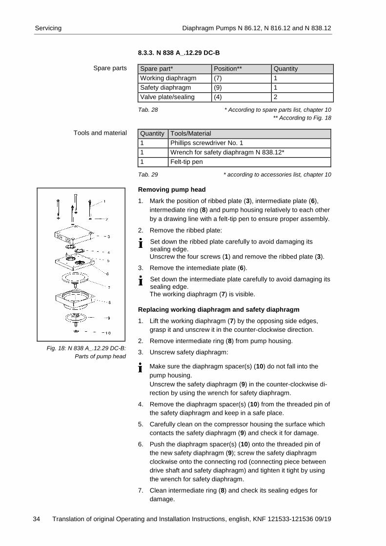
8.3.3. N 838 A_.12.29 DC-B
Spare part* Position** Quantity
Working diaphragm (7) 1
Safety diaphragm (9) 1
Valve plate/sealing (4) 2 Tab. 28 * According to spare parts list, chapter 10
** According to Fig. 18
Quantity Tools/Material
1 Phillips screwdriver No. 1
1 Wrench for safety diaphragm N 838.12*
1 Felt-tip pen Tab. 29 * according to accessories list, chapter 10
Removing pump head
1. Mark the position of ribbed plate (3), intermediate plate (6),
intermediate ring (8) and pump housing relatively to each other
by a drawing line with a felt-tip pen to ensure proper assembly.
2. Remove the ribbed plate:
Set down the ribbed plate carefully to avoid damaging its sealing edge. Unscrew the four screws (1) and remove the ribbed plate (3).
3. Remove the intemediate plate (6).
Set down the intermediate plate carefully to avoid damaging its sealing edge. The working diaphragm (7) is visible.
Replacing working diaphragm and safety diaphragm
1. Lift the working diaphragm (7) by the opposing side edges,
grasp it and unscrew it in the counter-clockwise direction.
2. Remove intermediate ring (8) from pump housing.
3. Unscrew safety diaphragm:
Unscrew the safety diaphragm (9) in the counter-clockwise di-
rection by using the wrench for safety diaphragm.
4. Remove the diaphragm spacer(s) (10) from the threaded pin of
the safety diaphragm and keep in a safe place.
5. Carefully clean on the compressor housing the surface which
contacts the safety diaphragm (9) and check it for damage.
6. Push the diaphragm spacer(s) (10) onto the threaded pin of
the new safety diaphragm (9); screw the safety diaphragm
clockwise onto the connecting rod (connecting piece between
drive shaft and safety diaphragm) and tighten it tight by using
the wrench for safety diaphragm.
7. Clean intermediate ring (8) and check its sealing edges for
damage.
Spare parts
Tools and material
Fig. 18: N 838 A_.12.29 DC-B:
Parts of pump head
Make sure the diaphragm spacer(s) (10) do not fall into the
pump housing.

Diaphragm Pumps N 86.12, N 816.12 and N 838.12 Servicing
Translation of original Operating and Installation Instructions, english, KNF 121533-121536 09/19 35
8. Place the intermediate ring (8) onto pump housing in accord-
ance with the felt-tip pen marking.
9. Screw the working diaphragm (7) clockwise onto the safety
diaphragm (9) and tighten hand-tight.
Replacing valve plates/sealings
1. Remove the valve plates/sealings (4) from the intermediate
plate (6).
2. Check the intermediate plate (6) and ribbed plate (3) for soiling
and damage. Clean the parts if necessary. Make sure that the
sealing edges of the ribbed plate (3) and intermediate plate (6)
are undamaged.
3. Contact KNF in case of roughness, scratches and corrosion.
Order and replace damaged parts.
4. Insert valve plates/sealings:
Upper and lower side of the valve plates/sealings are identical.
Lay new valve plates/sealings (4) in the valve seat of the in-
termediate plate (6).
5. Dispose of the old working diaphragm, safety diaphragm and
valve plates/sealings properly.
Mounting pump head
1. Place intermediate plate (6) on the intermediate ring (8) in
accordance with the felt-tip pen marking.
2. Place the ribbed plate (3) on the intermediate plate (6) in
accordance with the felt-tip pen marking. Position is indicated
by alignment pin (5).
3. Check the centering of the ribbed plate (3) by moving it slightly
from side to side.
4. Screw in the screws (1) with spacers (2) and tighten first only
slightly diagonally, then tight.
Perform a leak test in order to ensure the required gastight-
ness of the pump head after maintenance.

Troubleshooting Diaphragm Pumps N 86.12, N 816.12 and N 838.12
36 Translation of original Operating and Installation Instructions, english, KNF 121533-121536 09/19
9. Troubleshooting
Disconnect the pump power supply before working on the
pump.
Make sure the pump is de-energized and secure.
Check the pump (see Tab. 30 and 31).
Pump does not work
Cause Fault remedy
Pump not connected to the mains.
Connect pump to the mains.
No voltage in the mains. Check room fuse and switch on if necessary.
For N 838 A_.12.29 DC-B:
The motor board’s overcur-
rent protection circuit has
activated.
Maximum temperature of
motor board is exceeded
Maximum blocking time of
the rotor is exceeded
Separate pump from the mains.
Allow pump to cool.
Determine and remove the cause of the overcurrent (for example: improper pressure, liquid in the pump heads).
The pump must be separated from the mains for several seconds before the electronics will permit restarting.
Wrong polarity of the connection wires
Separate pump from the mains.
Be aware of right polarity of the connection wires and connect pump.
Connections or hoses are blocked.
Check hoses and connections.
Remove blockage.
External valve is closed or filter is clogged.
Check external valves and filters.
Condensate has collected in the pump head.
Detach the condensate source from the pump.
Flush the pump (see Chapter 8.2.1).
Install the pump at the highest point in the system.
Working diaphragm or valve plates/sealings are worn
Replace working diaphragm, safety diaphragm and valve plates/sealings (see Section 8.3).
Tab. 30
Flow rate, pressure or vacuum too low
The pump does not achieve the output specified in the Technical data or the data sheet.
Cause Fault remedy
Condensate has collected in the pump head.
Detach the condensate source from the pump.
Flush the pump (see Chapter 8.2.1).
Install the pump at the highest point in the system.
There is gauge pressure on pressure side and at the same time vacuum or a pressure above atmospheric pressure on suction side.
Change the pressure conditions.
Pneumatic lines or connection parts have an insufficient cross section.
Disconnect pump from system to determine output values.
Eliminate throttling (e.g. valve) if necessary.
Use lines or connection parts with larger cross section if necessary.

Diaphragm Pumps N 86.12, N 816.12 and N 838.12 Troubleshooting
Translation of original Operating and Installation Instructions, english, KNF 121533-121536 09/19 37
Flow rate, pressure or vacuum too low
The pump does not achieve the output specified in the Technical data or the data sheet.
Cause Fault remedy
Leaks occur on connections, lines or pump head.
Eliminate leaks.
Connections or lines completely or partially jammed.
Check connections and lines.
Remove the jamming parts and particles.
Head parts are soiled. Clean head components.
Working diaphragm or valve plates/sealings are worn.
Replace working diaphragm, safety diaphragm and valve plates/sealings (see Section 8.3).
Tab. 31
Fault visualization on motor controller (N 838 A_.12.29 DC-B only)
The excess of the overcurrent limit, the excess of the maximum
temperature of the motor board or the blocking of the rotor is
shown as a fault. A red LED on the BLDC motor controller signals
the cause of the fault.
Optional setting:
If desired, the motor controller can be programmed so that the
error output voltage exhibits the same characteristics as the LED.
With factory settings, only 1 or 0 are logically outputted as voltage
at the fault output.
Fig. 19: LED blinking duration according to different faults
To delete the error condition the motor has to be disconnected
from the mains.

Troubleshooting Diaphragm Pumps N 86.12, N 816.12 and N 838.12
38 Translation of original Operating and Installation Instructions, english, KNF 121533-121536 09/19
Fault cannot be rectified
If you are unable to determine any of the specified causes, send
the pump to KNF Customer Service (see last page for the ad-
dress).
1. Flush the pump under atmospheric conditions some minutes
with air (if necessary for safety reasons: with an inert gas) to
free the pump head of dangerous or aggressive gases (see
chapter 8.2.1).
2. Remove the pump.
3. Clean the pump (see chapter 8.2.2).
4. Send the pump, together with completed Health and Safety
Clearance and Decontamination Form, to KNF stating the na-
ture of the transferred medium.

Diaphragm Pumps N 86.12, N 816.12 and N 838.12 Spare parts and accessories
Translation of original Operating and Installation Instructions, english, KNF 121533-121536 09/19 39
10. Spare parts and accessories Spare Parts
N 86 AN.12.29 DC-B
Spare part Position* Order No.
Valve plate/sealing NBR (3) 111632
Working diaphragm NBR (5) 111634
Safety diaphragm NBR (7) 111637 Tab. 32 *according to Fig. 11
N 86 AP.12.29 DC-B
Spare part Position* Order No.
Valve plate/sealing EPDM (3) 112296
Working diaphragm EPDM (5) 026968
Safety diaphragm EPDM (7) 114152 Tab. 33 * according to Fig. 11
N 816 AV.12.29 DC-B
Spare part Position* Order No.
Valve plates FPM (3) 120014
O-ring FPM (4) 120014
Working diaphragm FPM (7) 118273
Safety diaphragm FPM (9) 114284 Tab. 34 * according to Fig. 12
N 838 AN.12.29 DC-B
Spare part Position* Order No.
Valve plate/sealing NBR (4) 112337
Working diaphragm NBR (7) 112339
Safety diaphragm NBR (9) 112341 Tab. 35 * according to Fig. 13
N 838 AP.12.29 DC-B
Spare part Position* Order No.
Valve plate/sealing EPDM (4) 112577
Working diaphragm EPDM (7) 027473
Safety diaphragm EPDM (9) 112578 Tab. 36 * according to Fig. 13

Spare parts and accessories Diaphragm Pumps N 86.12, N 816.12 and N 838.12
40 Translation of original Operating and Installation Instructions, english, KNF 121533-121536 09/19
Accessories
Accessory Order No.
Wrench for safety diaphragm: - N 86 A_.12.29 DC-B - N 816 AV.12.29 DC-B - N 838 A_.12.29 DC-B
115885 115885 115886
Tab. 37
Accessories for N 838 A_.12.29 DC-B
Accessory Order No.
PWM analog voltage converter 1.2V Function: Smoothing of the speed output signal into an analog voltage output and simultaneous transformation of 5V to 1.2V (optional 2.4V)
129011
External potentiometer Function: Setting of the speed via external potenti-ometer
300292
RS232-TTL-Translator Function: RS232- Level-Translator for customer specific plug versions
123779
Level-Translator RS232 Function: RS232 Level-Translator with SUB-D9 plug
128401
Level-Translator USB Function: RS232 Level-Translator with Micro-USB plug
128402
Tab. 38

Diaphragm Pumps N 86.12, N 816.12 and N 838.12 Returns
Translation of original Operating and Installation Instructions, english, KNF 121533-121536 09/19 41
11. Returns
Prerequisite for repairing a pump by KNF is a completed Decon-
tamination Form.
This is made available on the KNF website as a download. To find
the form, select your country on the overview page (www.knf.com).
You can find the Decontamination Form in the download area.
If you have questions, please contact your sales partner (contact
data: see www.knf.com).


KNF worldwide Find your local KNF partner on www.knf.com