operating ambient important - homedepot.com 18” (457.2 mm) clearance option described above is ......
TRANSCRIPT

2
For proper unit operation, check refrigerant charge using charginginformation located on control box cover and/or in the CheckCharge section of this instruction.
IMPORTANT: Maximum liquid--line size is 3/8--in. OD for allresidential applications including long line. Refer to ResidentialPiping and Longline Guideline for further information.
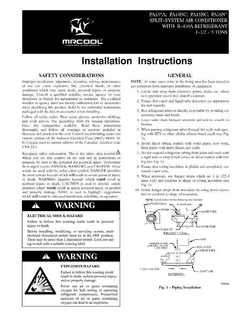
IMPORTANT: Always install the factory--supplied liquid--linefilter drier. If replacing the filter drier, refer to Product Data Digestfor appropriate part number. Obtain replacement filter driers fromyour distributor or branch.
INSTALLATIONIMPORTANT: Effective January 1, 2015, all split system andpackaged air conditioners must be installed pursuant to applicableregional efficiency standards issued by the Department of Energy.
CUT HAZARD
Failure to follow this caution may result in personal injury.
Sheet metal parts may have sharp edges or burrs. Use care andwear appropriate protective clothing and gloves whenhandling parts.
CAUTION!
Check Equipment and Job SiteUNPACK UNIT
Move to final location. Remove carton taking care not to damageunit.
Inspect EquipmentFile claim with shipping company prior to installation if shipmentis damaged or incomplete. Locate unit rating plate on unit cornerpanel. It contains information needed to properly install unit.Check rating plate to be sure unit matches job specifications.
Install on a Solid, Level Mounting PadIf conditions or local codes require the unit be attached to pad, tiedown bolts should be used and fastened through knockoutsprovided in unit base pan. Refer to unit mounting pattern in Fig. 2to determine base pan size and knockout hole location.
For hurricane tie downs, contact local distributor for details and PE(Professional Engineer) certification, if required by localauthorities.
On rooftop applications, mount on level platform or frame. Placeunit above a load--bearing wall and isolate unit and tubing set fromstructure. Arrange supporting members to adequately support unitand minimize transmission of vibration to building. Consult localcodes governing rooftop applications.
Roof mounted units exposed to winds may require wind baffles.Consult the Application Guideline and Service Manual --Residential Split System Air Conditioners and Heat Pumps forwind baffle construction.
NOTE: Unit must be level to within 2_ (3/8 in./ft ,.9.5 mm/m)per compressor manufacturer specifications.
Clearance RequirementsWhen installing, allow sufficient space for airflow clearance,wiring, refrigerant piping, and service. Allow 24 in. (609.6 mm)clearance to service end of unit and 48 in. (1219.2 mm) (aboveunit. For proper airflow, a 6--in. (152.4 mm) clearance on 1 side ofunit and 12--in. (304.8 mm) on all remaining sides must bemaintained. Maintain a distance of 24 in. (609.6 mm) betweenunits or 18 in. (457.2 mm) if no overhang within 12 ft. (3.66 m)Position so water, snow, or ice from roof or eaves cannot falldirectly on unit.
NOTE: 18” (457.2 mm) clearance option described above isapproved for outdoor units with wire grille coil guard only.Units with louver panels require 24” (609.6 mm) between units.
On rooftop applications, locate unit at least 6 in. (152.4 mm) aboveroof surface.
Operating AmbientThe minimum outdoor operating ambient in cooling mode withoutaccessory is 55_F (12.78_C). The maximum outdoor operatingambient in cooling mode is 125_F (51.7_C) for non--13 SEERmodels and 115_F (46.11_C) for 13 SEER models.
Make Piping Connections
! WARNINGPERSONAL INJURY AND ENVIRONMENTALHAZARD
Failure to follow this warning could result in personal injury ordeath.
Relieve pressure and recover all refrigerant before systemrepair or final unit disposal. Use all service ports and open allflow--control devices, including solenoid valves.
Federal regulations require that you do not vent refrigerant tothe atmosphere. Recover during system repair or final unitdisposal.
CAUTION!
UNIT DAMAGE HAZARD
Failure to follow this caution may result in equipmentdamage or improper operation.
If ANY refrigerant tubing is buried, provide a 6--in (152.4mm). vertical rise at service valve. Refrigerant tubing lengthsup to 36--in (914.4 mm). may be buried without furtherspecial consideration. Do not bury lines more than 36--in.(914.4 mm).
3/8--- in. (9.53 mm) Dia.Tiedown Knockouts inBasepan(2) Places
View From Top
UNIT BASE PANDimension in. (mm)
TIEDOWN KNOCKOUT LOCATIONS in. (mm)A B C
23---1/2 X 23---1/2(596.9 X 596.9) 7---13/16 (198.4) 4–7/16 (112.7) 18–1/16 (458.8)
26 X 26(660.4 X 660.4) 9–1/8 (231.8) 4–7/16 (112.7) 21–1/4 (539.8)
31–1/2 X 31–1/2(800.1 X 800.1) 9–1/8 (231.8) 6–9/16 (166.7) 24–11/16 (627.1)
35 X 35(889 X 889) 9–1/8 (231.8) 6–9/16 (166.7) 28–7/16 (722.3)
A05177
Fig. 2 -- Tiedown Knockout LocationsOutdoor units may be connected to indoor section using accessorytubing package or field--supplied refrigerant grade tubing of correctsize and condition. Rated tubing diameters shown in Table 1 arerecommended up to 80 ft. (24.38 m). See Product Data foracceptable alternate vapor diameters and associated capacity losses.For tubing requirements beyond 80 ft. (24.38 m), substantialcapacity and performance losses can occur. Following therecommendations in the Longline Guideline will reduce theselosses. Refer to Table 1 for field tubing diameters. Refer to Table 6for accessory requirements.

3
There are no buried--line applications greater than 36--in. (914.4mm) allowed.
If refrigerant tubes or indoor coil are exposed to atmosphere, theymust be evacuated to 500 microns to eliminate contamination andmoisture in the system.
Outdoor Unit Connected to Factory Approved IndoorUnitOutdoor unit contains correct system refrigerant charge foroperation with factory approved AHRI rated indoor unit whenconnected by 15 ft. (4.57 m) of field--supplied or factory--accessorytubing, and factory supplied filter drier. Check refrigerant chargefor maximum efficiency.
Refrigerant Tubing Connection OutdoorConnect vapor and liquid tubes to fittings on vapor and liquidservice valves (see Table 1). Use refrigerant grade tubing
Sweat Connection
CAUTION!UNIT DAMAGE HAZARD
Failure to follow this caution may result in equipmentdamage or improper operation.
Service valves must be wrapped in a heat--sinking materialsuch as a wet cloth while brazing.
Use refrigeration grade tubing. Service valves are closed fromfactory and ready for brazing. After wrapping service valve with awet cloth, braze sweat connections using industry acceptedmethods and materials. Consult local code requirements.Refrigerant tubing and indoor coil are now ready for leak testing.This check should include all field and factory joints.
Table 1 – Refrigerant Connections and Recommended Liquidand Vapor Tube Diameters (In.)
UNIT SIZE
LIQUID RATED VAPOR*Connection& Max. TubeDiameter
ConnectionDiameter
TubeDiameter
PA13NA, PA14NA, PA15NA, PA16NA, PA16NW18, 24 3/8 3/4 3/430 3/8 3/4 3/436 3/8 7/8 7/842, 48 3/8 7/8 7/860 3/8 7/8 1---1/8
PA16NA Models Only37, 49 3/8 7/8 7/861 3/8 7/8 1---1/8
* Units are rated with 25 ft. (7.6 m) of lineset. See Product Data sheet forperformance data when using different size and length linesets.
Notes:1. Do not apply capillary tube to these units.2. For Tubing Set lengths between 80 and 200 ft. (24.38 and 60.96 m)horizontal or 35 ft. (10.7 m) vertical differential 250 ft. (76.2 m) TotalEquivalent Length), refer to the Residential Piping and Longline Guideline--- Air Conditioners and Heat Pumps using R---410A refrigerant.
3. For alternate liquid line options on 18---42 size units, see Product Data orResidential Piping and Application Guideline
Install Liquid--Line Filter Drier Indoor
CAUTION!
UNIT DAMAGE HAZARD
Failure to follow this caution may result in equipmentdamage or improper operation.
1. Installation of filter drier in liquid line is required.
2. Filter drier must be wrapped in a heat--sinking materialsuch as a wet cloth while brazing.
Refer to Fig. 3 and install filter drier as follows:
1. Braze 5--in. liquid tube to the indoor coil.
2. Wrap filter drier with damp cloth.
3. Braze filter drier to above 5--in. (127 mm) liquid tube. Flowarrow must point towards indoor coil.
4. Connect and braze liquid refrigerant tube to the filter drier.
A05178
Fig. 3 -- Liquid Line Filter Drier
Evacuate Refrigerant Tubing and Indoor Coil
CAUTION!
UNIT DAMAGE HAZARD
Failure to follow this caution may result in equipmentdamage or improper operation.
Never use the system compressor as a vacuum pump.
Refrigerant tubes and indoor coil should be evacuated using therecommended deep vacuum method of 500 microns. The alternatetriple evacuation method may be used (see triple evacuationprocedure in service manual). Always break a vacuum with drynitrogen.
Deep Vacuum MethodThe deep vacuum method requires a vacuum pump capable ofpulling a vacuum of 500 microns and a vacuum gage capable ofaccurately measuring this vacuum depth. The deep vacuum methodis the most positive way of assuring a system is free of air andliquid water. A tight dry system will hold a vacuum of 1000microns after approximately 7 minutes. See Fig. 4.
500
MINUTES0 1 2 3 4 5 6 7
10001500
LEAK INSYSTEM
VACUUM TIGHTTOO WET
TIGHTDRY SYSTEM
2000MIC
RONS
250030003500400045005000
A95424
Fig. 4 -- Deep Vacuum Graph

4
Final Tubing CheckIMPORTANT: Check to be certain factory tubing on both indoorand outdoor unit has not shifted during shipment. Ensure tubesare not rubbing against each other or any sheet metal or wires.Pay close attention to feeder tubes, making sure wire ties on feedertubes are secure and tight.
Installing with Indoor PistonOutdoor Unit Connected to Factory Approved Indoor Unit
Check piston size shipped with indoor unit to see if it matchesrequired indoor piston size. If it does not match, replace indoorpiston with correct piston size. Refer to Product Data for pistonsize.
NOTE: Correct pistons are shipped with select outdoor units inthe accessory bag and are only for use in certain qualified andapproved fan coils, i.e. FB4C. (See Product Data for list ofapproved fan coils that use accessory piston.)The piston included with the FFMANP* and FPMAN* fan coilsare unique to those products and CANNOT be replaced with thepiston shipped with outdoor unit. Refer to the AHRI Directory tocheck if a certain combination can use a piston or requires anaccessory TXV.
When changing indoor piston, use a back−up wrench. Handtighten hex nut, then tighten with wrench 1/2 turn. Do not exceed30 ft−lbs. The indoor piston contains a Teflon ring (or seal) whichis used to seat against the inside of distributor body, and must beinstalled properly to ensure proper seating. See Fig 5.
13/16” BRASS HEX NUT
TEFLON® SEAL
TEFLON®RINGS
3/4” BRASS HEX BODY
“H” DISTRIBUTOR
PISTON RETAINERPISTON
A10342Fig. 5 -- Indoor (Cooling) Piston
Units with Cooling Mode TXV
Units installed with cooling mode TXV require charging by thesubcooling method.
1. Operate unit a minimum of 15 minutes before checkingcharge.
2. Measure liquid service valve pressure by attaching an accur-ate gage to service port.
3. Measure liquid line temperature by attaching an accuratethermistor type or electronic thermometer to liquid line nearoutdoor coil.
4. Refer to unit rating plate for required subcooling temperat-ure.
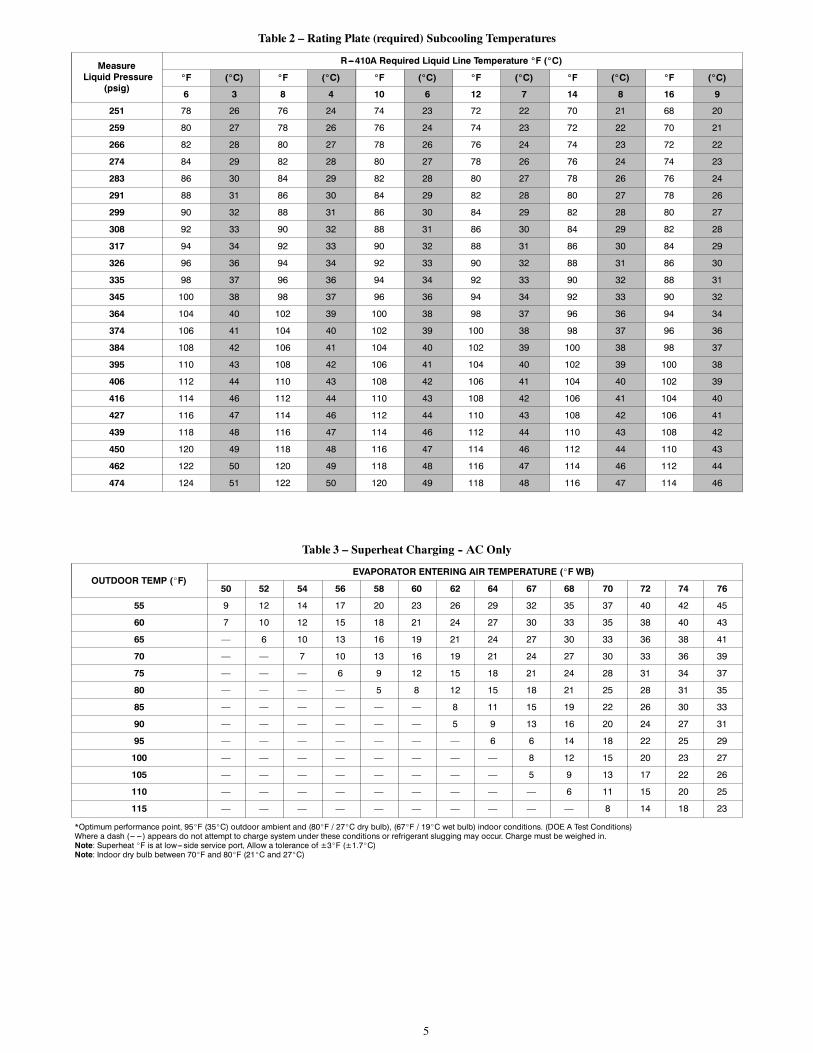
5. Refer to Table 2 -- Rating Plate (required) Subcooling Tem-perature. Find the point where required subcooling temper-ature intersects measured liquid service valve pressure.
6. To obtain required subcooling temperature at a specific li-quid line pressure, add refrigerant if liquid line temperatureis higher than indicated or reclaim refrigerant if temperatureis lower. Allow a tolerance of3_F (1.7_C).
NOTE: If conditions are not favorable see Check Chargeinstructions on page 8.
Units with Indoor Piston
Units installed with indoor pistons require charging by thesuperheat method.
The following procedure is valid when indoor airflow is within21 percent of its rated CFM.
1. Operate unit a minimum of 15 minutes before checkingcharge.
2. Measure suction pressure by attaching an accurate gage tosuction valve service port.
3. Measure suction temperature by attaching an accurate ther-mistor type or electronic thermometer to suction line at ser-vice valve.
4. Measure outdoor air dry--bulb temperature with thermomet-er.
5. Measure indoor air (entering indoor coil) wet--bulb temper-ature with a sling psychrometer.
6. Refer to Table 3 -- Superheat Charging -- AC Only. Findoutdoor temperature and evaporator entering air wet--bulbtemperature. At this intersection, note superheat. Where adash (----) appears on the table, do not attempt to charge sys-tem under these conditions or refrigerant slugging may oc-cur. Charge must be weighted in, adding or removing 0.6oz/ft of 3/8 liquid line above or below 15 feet (4.6m) re-spectively.
7. Refer to Table 4 -- Required Suction--Line Temperature.Find superheat temperature (from #6 above) and suctionpressure. At this intersection, note suction line temperature.
8. If unit has a higher suction line temperature than chartedtemperature, add refrigerant until charted temperature isreached.
9. If unit has a lower suction line temperature than chartedtemperature, reclaim refrigerant until charted temperature isreached.
10. When adding refrigerant, charge in liquid form into suctionservice port using a flow--restricting device.
11. If outdoor air temperature or pressure at suction valvechanges, charge to new suction line temperature indicatedon chart.
12. Optimum performance will be achieved when the operatingcharge produces 6_F suction superheat at suction servicevalve with 95_F (35_C) outdoor ambient and 80_F (27_C)dry bulb (67_F / 19_C) wet bulb) indoor temperature (DOE“A” test conditions) at rated airflow.
5
Table 2 – Rating Plate (required) Subcooling Temperatures
MeasureLiquid Pressure
(psig)
R---410A Required Liquid Line Temperature _F (_C)
_F (_C) _F (_C) _F (_C) _F (_C) _F (_C) _F (_C)
6 3 8 4 10 6 12 7 14 8 16 9
251 78 26 76 24 74 23 72 22 70 21 68 20
259 80 27 78 26 76 24 74 23 72 22 70 21
266 82 28 80 27 78 26 76 24 74 23 72 22
274 84 29 82 28 80 27 78 26 76 24 74 23
283 86 30 84 29 82 28 80 27 78 26 76 24
291 88 31 86 30 84 29 82 28 80 27 78 26
299 90 32 88 31 86 30 84 29 82 28 80 27
308 92 33 90 32 88 31 86 30 84 29 82 28
317 94 34 92 33 90 32 88 31 86 30 84 29
326 96 36 94 34 92 33 90 32 88 31 86 30
335 98 37 96 36 94 34 92 33 90 32 88 31
345 100 38 98 37 96 36 94 34 92 33 90 32
364 104 40 102 39 100 38 98 37 96 36 94 34
374 106 41 104 40 102 39 100 38 98 37 96 36
384 108 42 106 41 104 40 102 39 100 38 98 37
395 110 43 108 42 106 41 104 40 102 39 100 38
406 112 44 110 43 108 42 106 41 104 40 102 39
416 114 46 112 44 110 43 108 42 106 41 104 40
427 116 47 114 46 112 44 110 43 108 42 106 41
439 118 48 116 47 114 46 112 44 110 43 108 42
450 120 49 118 48 116 47 114 46 112 44 110 43
462 122 50 120 49 118 48 116 47 114 46 112 44
474 124 51 122 50 120 49 118 48 116 47 114 46
Table 3 – Superheat Charging -- AC Only
OUTDOOR TEMP (_F)EVAPORATOR ENTERING AIR TEMPERATURE (_F WB)
50 52 54 56 58 60 62 64 67 68 70 72 74 76
55 9 12 14 17 20 23 26 29 32 35 37 40 42 45
60 7 10 12 15 18 21 24 27 30 33 35 38 40 43
65 — 6 10 13 16 19 21 24 27 30 33 36 38 41
70 — — 7 10 13 16 19 21 24 27 30 33 36 39
75 — — — 6 9 12 15 18 21 24 28 31 34 37
80 — — — — 5 8 12 15 18 21 25 28 31 35
85 — — — — — — 8 11 15 19 22 26 30 33
90 — — — — — — 5 9 13 16 20 24 27 31
95 — — — — — — — 6 6 14 18 22 25 29
100 — — — — — — — — 8 12 15 20 23 27
105 — — — — — — — — 5 9 13 17 22 26
110 — — — — — — — — — 6 11 15 20 25
115 — — — — — — — — — — 8 14 18 23
*Optimum performance point, 95_F (35_C) outdoor ambient and (80_F / 27_C dry bulb), (67_F / 19_C wet bulb) indoor conditions. (DOE A Test Conditions)Where a dash (--- --- ) appears do not attempt to charge system under these conditions or refrigerant slugging may occur. Charge must be weighed in.Note: Superheat _F is at low--- side service port, Allow a tolerance of ±3_F (±1.7_C)Note: Indoor dry bulb between 70_F and 80_F (21_C and 27_C)

6
Table 4 – Required Suction--Line Temperature
SUPERHEAT TEMP (_F)SUCTION PRESSURE AT SERVICE PORT (PSIG)
107.8 112.2 116.8 121.2 126 130.8 138.8 140.8 145.8
0 35 37 39 41 43 45 47 49 51
2 37 39 41 43 45 47 49 51 53
4 39 41 43 45 47 49 51 53 55
6 41 43 45 47 49 51 53 55 57
8 43 45 47 49 51 53 55 57 59
10 45 47 49 51 53 55 57 59 61
12 47 49 51 53 55 57 59 61 63
14 49 51 53 55 57 59 61 63 65
16 51 53 55 57 59 61 63 65 67
18 53 55 57 59 61 63 65 67 69
20 55 57 59 61 63 65 67 69 71
22 57 59 61 63 65 67 69 71 73
24 59 61 63 65 67 69 71 73 75
26 61 63 65 67 69 71 73 75 77
28 63 65 67 69 71 73 75 77 79
30 65 67 69 71 73 75 77 79 81
32 67 69 71 73 75 77 79 81 83
34 69 71 73 75 77 79 81 83 85
36 71 73 75 77 79 81 83 85 87
38 73 75 77 79 81 83 85 87 89
40 75 77 79 81 83 85 87 89 91

7
Make Electrical ConnectionsBe sure field wiring complies with local and national fire, safety,and electrical codes, and voltage to system is within limits shownon unit rating plate. Contact local power company for correction ofimproper voltage. See unit rating plate for recommended circuitprotection device.
NOTE: Operation of unit on improper line voltage constitutesabuse and could affect unit reliability. See unit rating plate. Do notinstall unit in system where voltage may fluctuate above or belowpermissible limits.
NOTE: Use copper wire only between disconnect switch and unit.
NOTE: Install branch circuit disconnect of adequate size per NECto handle unit starting current. Locate disconnect within sight fromand readily accessible from unit, per Section 440--14 of NEC.
Route Ground and Power WiresRemove access panel to gain access to unit wiring. Extend wiresfrom disconnect through power wiring hole provided and into unitcontrol box.
! WARNINGELECTRICAL SHOCK HAZARD
Failure to follow this warning could result in personal injury ordeath.
The unit cabinet must have an uninterrupted or unbrokenground to minimize personal injury if an electrical fault shouldoccur. The ground may consist of electrical wire or metalconduit when installed in accordance with existing electricalcodes.
Connect Ground and Power WiresConnect ground wire to ground connection in control box forsafety. Connect power wiring to contactor as shown in Fig. 6.
DISCONNECTPER N.E.C. AND/ORLOCAL CODES
CONTACTOR
GROUNDLUG
FIELD GROUND
WIRING
FIELD POWER
WIRING
BLUE3 PHASE ONLY
A94025
Fig. 6 -- Line Connections
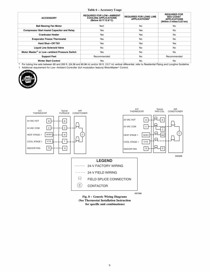
Connect Control WiringRoute 24--v control wires through control wiring grommet andconnect leads to control wiring (See Fig. 8). Refer to InstallationInstructions packaged with thermostat.
Use No. 18 AWG color--coded, insulated (35_C minimum) wire. Ifthermostat is located more than 100 ft. (30.48 m) from unit, asmeasured along the control voltage wires, use No. 16 AWGcolor--coded wire to avoid excessive voltage drop.
All wiring must be NEC Class 2 and must be separated fromincoming power leads.
Use furnace transformer, fan coil transformer, or accessorytransformer for control power, 24v/40va minimum.
NOTE: Use of available 24v accessories may exceed theminimum 40va power requirement. Determine total transformerloading and increase the transformer capacity or split the load withan accessory transformer as required.
Final Wiring CheckIMPORTANT: Check factory wiring and field wire connections toensure terminations are secured properly. Check wire routing toensure wires are not in contact with tubing, sheet metal, etc.
Compressor Crankcase HeaterWhen equipped with a crankcase heater, furnish power to heater aminimum of 24 hr before starting unit. To furnish power to heateronly, set thermostat to OFF and close electrical disconnect tooutdoor unit.
A crankcase heater is required if refrigerant tubing is longer than80 ft. (24.38 m). Refer to the Residential Piping and LonglineGuideline and Service Manual Longline Section--ResidentialSplit--System Air Conditioners and Heat Pumps.
Install Electrical AccessoriesRefer to the individual instructions packaged with kits oraccessories when installing.
Start--Up
CAUTION!UNIT OPERATION AND SAFETY HAZARD
Failure to follow this caution may result in personal injury,equipment damage or improper operation.S Do not overcharge system with refrigerant.
S Do not operate unit in a vacuum or at negative pressure.
S Compressor dome temperatures may be hot.
CAUTION!
PERSONAL INJURY HAZARD
Failure to follow this caution may result in personal injury.
Wear safety glasses, protective clothing, and gloves whenhandling refrigerant and observe the following:S Front seating service valves are equipped with Schrader
valves.
Follow these steps to properly start up system:1. After system is evacuated, fully open liquid and vapor ser-vice valves.
2. Unit is shipped with valve stem(s) front seated (closed) andcaps installed. Replace stem caps after system is opened torefrigerant flow. Replace caps finger--tight and tighten withwrench an additional 1/12 turn.
3. Close electrical disconnects to energize system.
4. Set room thermostat at desired temperature. Be sure setpoint is below indoor ambient temperature.
5. Set room thermostat to COOL and fan control to ON orAUTO mode, as desired. Operate unit for 15 minutes.Check system refrigerant charge.
8
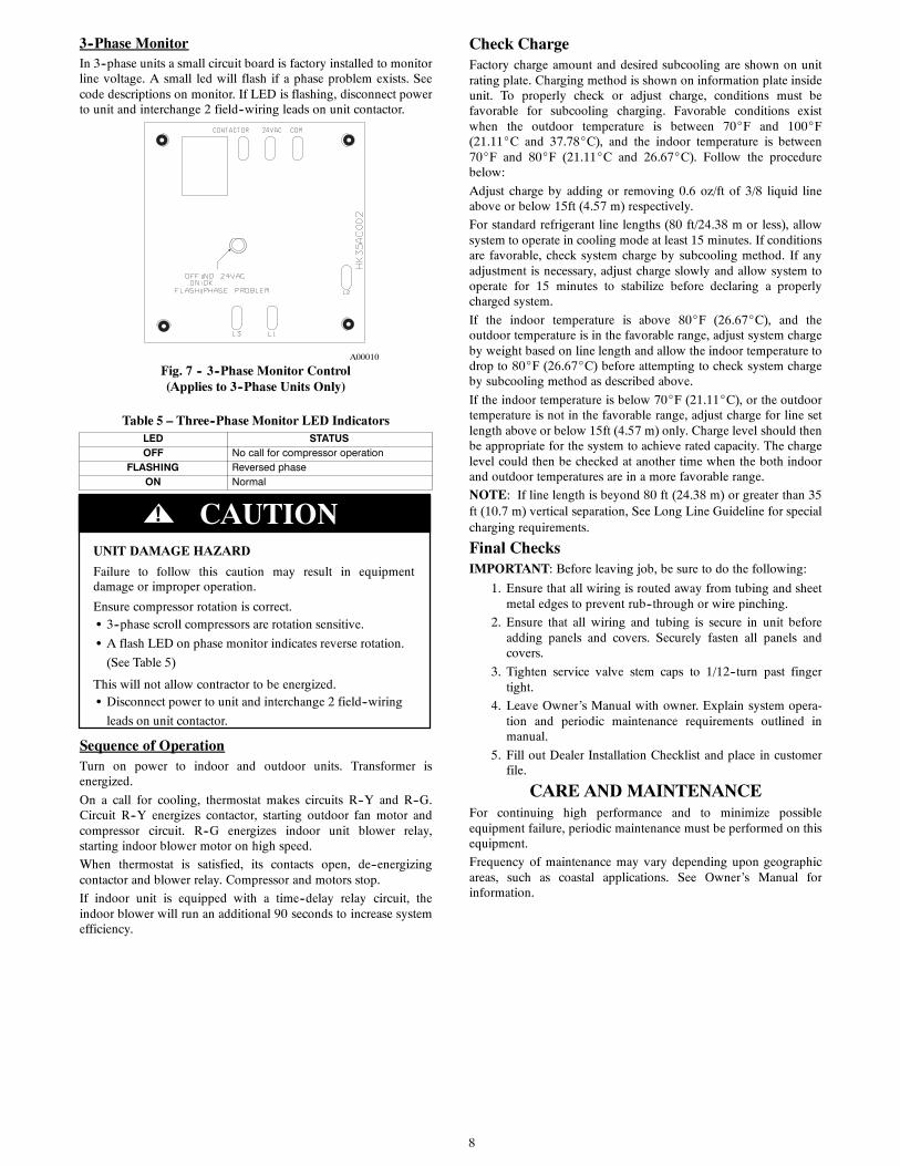
3--Phase MonitorIn 3--phase units a small circuit board is factory installed to monitorline voltage. A small led will flash if a phase problem exists. Seecode descriptions on monitor. If LED is flashing, disconnect powerto unit and interchange 2 field--wiring leads on unit contactor.
A00010
Fig. 7 -- 3--Phase Monitor Control(Applies to 3--Phase Units Only)
Table 5 – Three--Phase Monitor LED IndicatorsLED STATUSOFF No call for compressor operation
FLASHING Reversed phaseON Normal
UNIT DAMAGE HAZARD
Failure to follow this caution may result in equipmentdamage or improper operation.
Ensure compressor rotation is correct.S 3--phase scroll compressors are rotation sensitive.
S A flash LED on phase monitor indicates reverse rotation.
(See Table 5)
This will not allow contractor to be energized.S Disconnect power to unit and interchange 2 field--wiring
leads on unit contactor.
CAUTION!
Sequence of OperationTurn on power to indoor and outdoor units. Transformer isenergized.
On a call for cooling, thermostat makes circuits R--Y and R--G.Circuit R--Y energizes contactor, starting outdoor fan motor andcompressor circuit. R--G energizes indoor unit blower relay,starting indoor blower motor on high speed.
When thermostat is satisfied, its contacts open, de--energizingcontactor and blower relay. Compressor and motors stop.
If indoor unit is equipped with a time--delay relay circuit, theindoor blower will run an additional 90 seconds to increase systemefficiency.
Check ChargeFactory charge amount and desired subcooling are shown on unitrating plate. Charging method is shown on information plate insideunit. To properly check or adjust charge, conditions must befavorable for subcooling charging. Favorable conditions existwhen the outdoor temperature is between 70_F and 100_F(21.11_C and 37.78_C), and the indoor temperature is between70_F and 80_F (21.11_C and 26.67_C). Follow the procedurebelow:
Adjust charge by adding or removing 0.6 oz/ft of 3/8 liquid lineabove or below 15ft (4.57 m) respectively.
For standard refrigerant line lengths (80 ft/24.38 m or less), allowsystem to operate in cooling mode at least 15 minutes. If conditionsare favorable, check system charge by subcooling method. If anyadjustment is necessary, adjust charge slowly and allow system tooperate for 15 minutes to stabilize before declaring a properlycharged system.
If the indoor temperature is above 80_F (26.67_C), and theoutdoor temperature is in the favorable range, adjust system chargeby weight based on line length and allow the indoor temperature todrop to 80_F (26.67_C) before attempting to check system chargeby subcooling method as described above.
If the indoor temperature is below 70_F (21.11_C), or the outdoortemperature is not in the favorable range, adjust charge for line setlength above or below 15ft (4.57 m) only. Charge level should thenbe appropriate for the system to achieve rated capacity. The chargelevel could then be checked at another time when the both indoorand outdoor temperatures are in a more favorable range.
NOTE: If line length is beyond 80 ft (24.38 m) or greater than 35ft (10.7 m) vertical separation, See Long Line Guideline for specialcharging requirements.
Final ChecksIMPORTANT: Before leaving job, be sure to do the following:
1. Ensure that all wiring is routed away from tubing and sheetmetal edges to prevent rub--through or wire pinching.
2. Ensure that all wiring and tubing is secure in unit beforeadding panels and covers. Securely fasten all panels andcovers.
3. Tighten service valve stem caps to 1/12--turn past fingertight.
4. Leave Owner’s Manual with owner. Explain system opera-tion and periodic maintenance requirements outlined inmanual.
5. Fill out Dealer Installation Checklist and place in customerfile.
CARE AND MAINTENANCEFor continuing high performance and to minimize possibleequipment failure, periodic maintenance must be performed on thisequipment.
Frequency of maintenance may vary depending upon geographicareas, such as coastal applications. See Owner’s Manual forinformation.
9
Table 6 – Accessory Usage
ACCESSORYREQUIRED FOR LOW---AMBIENTCOOLING APPLICATIONS(Below 55F/12.8_C)
REQUIRED FOR LONG LINEAPPLICATIONS*
REQUIRED FORSEA COASTAPPLICATIONS
(Within 2 miles/3.22 km)
Ball Bearing Fan Motor Yes{ No No
Compressor Start Assist Capacitor and Relay Yes Yes No
Crankcase Heater Yes Yes No
Evaporator Freeze Thermostat Yes No No
Hard Shut---Off TXV Yes Yes Yes
Liquid Line Solenoid Valve No No No
Motor Master or Low---ambient Pressure Switch Yes No No
Support Feet Recommended No Recommended
Winter Start Control Yes No No* For tubing line sets between 80 and 200 ft. (24.38 and 60.96 m) and/or 35 ft. (10.7 m) vertical differential, refer to Residential Piping and Longline Guideline.{ Additional requirement for Low---Ambient Controller (full modulation feature) MotorMasterr Control.
24 VAC HOT
24 VAC COM
R
C
G
W/W1
Y/Y2
R
C
C
A/CTHERMOSTAT
TypicalFAN COIL
AIRCONDITIONER
G
W2HEAT STAGE 1
COOL STAGE 1
INDOOR FAN
24 VAC HOT
24 VAC COM
R
C
G
W/W1
Y/Y2
R
C
C
A/CTHERMOSTAT
TypicalFURNACE
AIRCONDITIONER
Y
G
WHEAT STAGE 1
COOL STAGE 1
INDOOR FAN
A02326
LEGEND24-V FACTORY WIRING
24-V FIELD WIRING
FIELD SPLICE CONNECTION
CONTACTORC
A97368
Fig. 8 -- Generic Wiring Diagrams(See Thermostat Installation Instruction
for specific unit combinations)
IM