operate manual - sah.co.rs file2)kp: proportion parameters; ki: integral parameter; kd:...
TRANSCRIPT

XC series BD board for special functions Operate Manual
Xinje Electronic Co., Ltd.


i
Catalog 1. CONFIGURE METHOD OF BD BOARD .................................................................................................. 1
2. ANALOG INPUT AND TEMPERATURE SAMPLING BOARD XC-2AD2PT-BD ............................... 2
3. ANALOG I/O EXPANSION BD BOARD XC-2AD2DA-BD...................................................................... 9
4. COMMUNICATION EXTEND CARD XC-COM-BD ............................................................................. 13
5. XC-SD-BD FOR SD CARD ......................................................................................................................... 15
6. ETHERNET EXPANSION BOARD XC-TBOX-BD ................................................................................ 27
7. WEIGHING EXPANSION BD XC-WT-BD .............................................................................................. 37
8. FIBER OPTICAL COMMUNICATION EXPANSION BD XC-OFC-BD ............................................. 41
9. PROFIBUS EXPANSION BD BOARD XC-PBOX-BD ............................................................................ 45

ii

1. Configure method of BD board Configure method of BD board:
1) Install BD board correctly to the main unit; 2) Then, online with XCP edit tool, in “Window” menu, chose “Configure BD Board” (see graph 1) 3) Then, in “BD Board Configure”, choose “Other BD” (see graph 2), download user program.
Graph1 Graph2

2. Analog input and temperature sampling board XC-2AD2PT-BD 1、Characteristic:
2、General Specification
Item Voltage input Temperature input
Analog input signal DC0~5V、0~10V(Input resistor 300kΩ) Platinum resistor Pt100(2-line
format) Temperature testing
bound - -100~350℃
Distinguish ratio 0.15mV(10/16383) 0.1℃ Digital output bound 0~16383 -1000~3500 Colligate precision ±0.8% of the full-scale
Convert time 15ms×4 channels PID output value 0~K4095 No-load defaulted
value 0 3500
Input characteristic
Insulation No insulation between each channel of PLC
I/O engross 0 I/O (Since it is operated via data register, so it is not limited by main PLC’s
standard max. control points)
14 bits high precise analog input. 2 channels voltage 0~10V 、 0~5V selective, 2
channels temperature analog input. Platinum temperature testing resistor (Pt100 two-line
format), temperature sensor using analog input.

3、External installation and connection
1) Installation method of expansion board: Open the cover in the left of PLC (see the following dashed line), then insert the board to the PLC
according to the pins, fix with the screws, close the PLC cover to finish.
2)Connection method:See the following graph
10
45
32
677
6
XC3-32R-E
ERR
RUN
23
54
01
0V24V
BA
Y0COM0
Y1
COM1
Y2CO
M2Y3
Y4Y1
0CO
M4Y11
Y6Y7
Y5CO
M3Y1
2Y13
Y14Y15
PORT2
PORT1
X Y
PWR
X21
X20
X17
X10
X11X12X13X14
X16
X15
X7
X6X5
X4X3
X2X1
X0COM
COM
FG
PT100
PT100
V-
V+
V-
V+

4、Distribution of input define ID This BD board doesn’t engross any I/O unit, the converted value will be sent to PLC register directly,
the channel’s correspond PLC register ID is:
Channel’s ID
AD signal/te-mperature
PID output value
The set data/temp-erature
Kp Ki Kd Diff Death start/sto
-p
0CH ID1000 ID1004 QD1000 QD1004
QD1005
QD1006 QD1007 QD1008 Y1000
1CH ID1001 ID1005 QD1001 Y1001 2CH ID1002 ID1006 QD1002
QD1009 QD101
0 QD1011 QD1012 -
Y1002 3CH ID1003 ID1007 QD1003 Y1003
Description: 1)0CH、1CH are AD input channels; 2CH、3CH are Pt input channels.
2)Kp: proportion parameters; Ki: integral parameter; Kd: differential parameters; Diff: control bound Control bound Diff:in the assigned bound, carry on PID control, beyond that bound, don’t carry on that control Start signal (Y): if Y is 0, close PID control, if Y is 1, start PID control. Death bound Death: it means the current PID control value compares with the preceding PID
control value, if the difference between them is less than the set bound of death, the module will abandon the current PID control value, send the preceding PID control value to the PLC main unit.
3.Setting of working mode
2)Each channel’s working mode is assigned by 4 bits in the correspond register. Each bit’s definition is shown
below: Register FD8306:
FD8306 H O O O O 0CH 1CH 2CH 3CH
1)For expansion’s input/output, they both have option of voltage 0~5V、0~10V, current 0~20mA、4~20mA modes and sieve format. Setting via special FLASH data register FD. See the left graph:

5、Control specification
1)Usage of the four parameters: proportion parameter(Kp)、integral parameter(Ki)、differential parameter(Kd)、control proportion band(Diff).
a.) Parameter P is proportion parameter, mainly reflect system’s difference, as soon as the difference occurs, carry on control to decrease the difference. b.) Parameter I is integral parameter, mainly used to remove the whisht difference, improve the system’s no difference degree. c.) Parameter D is differential parameter, mainly used to control signal’s changing trend, decrease the
shake of system. Temperature control bound means: in the assigned bound, carry on PID control, beyond this bound,
don’t go on PID control.
2) Control specification The PID regulate bound is(QD-Diff,QD+Diff),when the temperaure is below QD-Diff,the controller heat up ,when the temperature is higher than QD+Diff,the controller stop heating.
Temperature-control curve of PID:
Channel 1 Channel 0 Bit7 Bit6 Bit5 Bit4 Bit3 Bit2 Bit1 Bit0
00:1/2 sieve 01: not sieve 10:1/3 sieve 11:1/4 sieve
-
0:0~10V 1:0~5V
00:1/2 sieve 01:not sieve 10:1/3 sieve 11:1/4 sieve
-
0:0~10V 1:0~5V
- -
Channel 3 Channel 2 Bit15 Bit14 Bit13 Bit12 Bit11 Bit10 Bit9 Bit8
00:1/2 sieve 01:not sieve 10:1/3 sieve 11:1/4 sieve
- -
00:1/2 sieve 01:not sieve 10:1/3 sieve 11:1/4 sieve
- -

3) Each parameter’s reference value:Kp=20~100;Ki=5~20;Kd=200~800;DIFF=100~200;
These reference values are only used for normal condition’s reference, according to the field’s detailed condition, each parameter’s value could be set beyond the set bound.
6、Application of PID output value
When carry on temperature PID regulation, the module will output a PID control value every 2 seconds. So, in the PLC program, we could carry on heat control with the duty ratio formed by PID output vale and K4095 in 2 seconds! Assume PID output value is X(0≤X≤4095),in the cycle of 2 seconds, carry on duty ratio control, 2X/4095 seconds heater output, (2-2X/4095) seconds heater close output.

7、Program E.g.1、real time read data of channel 0, and carry on PID adjustment of channel 0.
MOV K800 QD1000
MOV ID1000 D10
M8000
END
MOV K30 QD1004
MOV K5 QD1005
MOV K500 QD1006
MOV K150 QD1007
MOV K200 QD1008
MOV ID1004 D1000
Y1000M8
Write the input value of channel 0 into D10
Set channel 0’s value as 800
Set channel 0’s proportion coefficient Kp as 30
Set channel 0’s integral coefficient Ki as 5
Set channel 0’s differential coefficient Kd as 500
Set the control bound (Diff) of channel 0 as 150
Set the dead bound (Death) of channel 0 as 200
Write PID output value of channel 0 into D1000
Start/stop the adjustment of channel 0

E.g.2、example of PID temperature control
MOV K800 QD1002
MOV ID1006 D1000
MUL D1000 K200
DDIV D1100 K4095
D1100
D1200
M8000
M8000
T200 K200T200
T200 D1200≤ Y3
Y1000M10
END
MOV K30 QD1009
MOV K5 QD1010
MOV K500 QD1011
MOV K150 QD1012
D1100>
K0
T200 is 10mS timer
Convert the PID output value (0~4095) into value of 0~200
Via the connection and disconnection of Y3, carry on PID temperature adjustment
Start/stop channel 2
Set value of channel 2 as 800 (80 degrees)
Set the proportion coefficient Kp of channel 2 as 30
Set the integral coefficient Ki of channel 2 as 5
Set the differential coefficient Kd of channel 2 as
Set the control bound Diff of channel 2 as 150

扩展板的安装位置
3. Analog I/O expansion BD board XC-2AD2DA-BD 1. Characteristics
2. General specifications
Item Voltage input Current output Analog input range DC0~5V, 0~10V(input resistor 300kΩ) -
Analog output range - DC0~20mA、 4~20mA (external load resistor is less than 500Ω)
Resolution 1/16383(14Bit); the transformed data is saved as hex in the PLC
1/1023(10Bit); the transformed data is saved as hex in the PLC
Digital output range 14 bits binary data (0~16383) - Digital input range - 10 bits binary data (0~1023) Integrated precision ±0.8% of the full scale Transformation time 15ms×2 channel 3ms/1 channel PID output value 0~K1023 - Insulation There is no insulation among each PLC channel
I/O occupy 0 point (the module operate the data via PLC registers, it will not be limited by PLC max I/O points)
3. Connection and Installation (1) Installation:
Open the cover on the left side of PLC, insert the expansion BD board into the pins, then fix it with the screw, then close the cover.
FGCOM
COM X0X1
X2X3
X4X5
X6X7 X15
X16X14X13
X12X11
X10X17
X20X21
PWR
Y
X
PORT1 PORT2
Y15Y14
Y13Y12COM3
Y5Y7
Y6Y11
COM4Y10Y4
Y3COM2Y2
COM1Y1
COM0Y0
AB24V
0V
10 4 532
RUN
ERR
XC3-32R-E
6 7
762 3 540 1
14 bits high precision analog input 10 bits high precision analog output 2 channels 0-10V, 0-5V voltage input choices 2 channels 0-20mA, 4-20mA current output choices
Installation position

(2) Connection:
10
45
32
677
6
XC3-32R-E
ERR
RUN
23
54
01
0V24
VB
AY0
COM0
Y1CO
M1Y2
COM2
Y3Y4
Y10
COM4
Y11
Y6Y7
Y5CO
M3Y1
2Y1
3Y1
4Y1
5
PORT2
PORT1
X Y
PWR
X21
X20
X17
X10X11X1
2X1
3X1
4X1
6X1
5X7
X6X5
X4X3
X2X1
X0CO
MCO
MFG
VI0+
VI0-
VI1+
VI1-
AO0+
AO0-
AO1+
AO1-
4. I/O address assignment The BD board will not occupy I/O space, the transformed data will be saved in PLC registers. The PLC
registers are as the following:
Channel AD signal PID output PID control bit Set value PID parameters: Kp, Ki, Kd, Diff,
Death
0CH ID1000 ID1002 Y1000 QD1002 Kp-----QD1004;Ki-----QD1005; Kd-----QD1006;Diff---QD1007; Death--QD1008 1CH ID1001 ID1003 Y1001 QD1003
Channel DA signal - - -
- 0CH QD1000 - - -
1CH QD1001 - - -
Notes: 1) 0CH, 1CH are AD input channels; 2CH, 3CH are DA output channels.
2) Kp: proportion, Ki: integral, Kd: differential, Diff: control range Diff: to do PID control in appointed area. PID control bit (Y): Y=0, PID control is unable; Y= 1, PID control is able. Death: to compare the former and the current PID control value, if the difference is less than death area,
the module will abandon the current PID control value and send the former value into the PLC.

5. Working mode
2) One register has 16 bits, every 4 bits can decide one channel’s working mode. Register FD8306:
6. AD transformation diagram
The relationship between input analog and transformed digital data:
0~5V analog input 0~10V analog input
The relationship between input digital and transformed analog data:
0~20mA analog output 4~20mA analog output
Note: If the output data is more than K1023, D/A result will be 20mA.
Channel 1 Channel 0 Bit7 Bit6 Bit5 Bit4 Bit3 Bit2 Bit1 Bit0
00:1/2 filter 01:no filter 10:1/3 filter 11:1/4 filter
-
0:0~10V 1:0~5V
00:1/2 filter 01:no filter 10:1/3 filter 11:1/4 filter
-
0:0~10V 1:0~5V
- -
Channel 3 Channel 2 Bit15 Bit14 Bit13 Bit12 Bit11 Bit10 Bit9 Bit8
- - 0:0~20mA 1:4~20mA
- - 0:0~20mA 1:4~20mA
FD8306 H O O O O 0CH 1CH 2CH 3CH
1) The expansion BD board has 0-5V and 0-10V voltage input choices; 0-20mA, 4-20mA current output choices. They can be set by FLASH register in the PLC. As the right diagram showing, each register can decide the modes of 4 channels. Every 4 bits of the register can decide one channel’s mode.

7. Example Read the real time data of 2 channels; write the data in 2 channels.
Explanation: M8000 is always ON when PLC is running.
When PLC is running, it writes the channel 0 data of model 1to register D0 of PLC. Module 1 PLC
Channel 1 data D1
Channel 0 D10
Channel 1 D11

4. Communication extend card XC-COM-BD 1、 Characteristic
2、Installation and connection 1) Installation: Open the PLC cover on the left, insert the card into the pins, fix it with screw and close the cover.
FGCOM
COM X0X1
X2X3
X4X5
X6X7 X15
X16X14X13
X12X11
X10X17
X20X21
PWR
Y
X
PORT1 PORT2
Y15Y14
Y13Y12COM3
Y5Y7
Y6Y11
COM4Y10Y4
Y3COM2Y2
COM1Y1
COM0Y0
AB24V
0V
10 4 532
RUN
ERR
XC3-32R-E
6 7
762 3 540 1
2) Connection:
RS485 communication port RS232 communication port RS485 and RS232 can not be used at the same
time
The place to install the card

Notes: (1) TXD, RXD, GND are RS232 communication port. (2) A, B are RS485 communication port. (3) RS232 and RS485 can not be used at the same time. 3、XC software setting When using the BD board, please select the BD serial port in the XCPpro software:

5. XC-SD-BD for SD card 1. Characteristic
2. Explanation
1) SD card XC-SD-BD has not been installed the SD card when out of factory, user needs to prepare MicroSD ( TF card ), the card memory should be not more than 2GB. Before install the SD card in the XC-SD-BD, please use card reader to format the SD to FAT16 in the PC. SD card supports hot plug, but please wait for at least 5 second after hot plug. 2) The file standard in SD card SD card supports .csv file, these file should be saved in the root directory. All the .csv files must be named as dataxxx.csv, xxx is the file index number, the range is 001~999, when
xxx is less than 100, add 0 from the left side. For example, if file index number is 1, the file name will be data001.csv.
3) Data format and type in SD card SD card supports 4 kinds of data type: single word (W), double word (DW), float(Fm.n), character (Sx). The data range and space:
Data type W DW Fm.n(m<=15,n<=15) Sx(x<=16)
Data range -32768~32767
-2147483648~2147483647
-18446742974197923840~18446742974197923840
\
Character occupied in SD card
6 11 m+1+n 2*x
WORD number 1 2 2 x NOTE: (1) When the real data length is less than the character length in SD card, add space from the left side. For
example, single word data 454, data type is W, character length is 6, so add 6-3 = 3 spaces. The real number is ∟∟∟454. (∟ is space ).
(2) When Fm.n is negative number, the sign bit occupies one character. For example, F5.3, after writing the number -12345.123 in SD card, the lowest valid bit will be deleted; the number will become -12345.12.
(3) The x of character Sx means word length, but not character length. 3. Operation for the SD XC series PLC can connect SD card, write and read the data from the SD card. 1) Read the SD card
To install SD card and expand the XC memory PLC can read and write the data of SD card Support 4 data formats ( single word, double word,
float, character ) XC hardware version V3.2 and above is required

After installing the SD card successfully, PLC can read the SD card data. Use FROM instruction to read the appointed data block in .csv file of SD card.
Read the data from SD card to PLC, unit is word. S1: K7 means the object is XC-SD-BD. S2~S2+2: appoint .csv file index number, the column head address of data block, the row head address of
data block. Operand is D. In the example, D200 is the .csv file index number D201 is the column head address of the data block D202 is the row head address of the data block S3: the word numbers you want to read out. Operand is D. D1: save the data in PLC register. Operand is D. In this example, if D200=2, D201=1, D202=3, D210=3. The instruction will do like this: read 3 numbers start from column 1, row 2 of the file “data002.csv” in SD card, and save it in D220 of PLC. If the data002.csv is shown as the following, then the numbers in the red color line will be read.
Explanation: (1) In the data002.csv file, the first line is data type definition; this line is included in the row address. (2) The number “2471” is W type, “-191280” is DW type, so totally 3 words, the same as the read out word
numbers. 2) Write SD card By TO instruction, PLC can write the data into appointed location in .csv file of SD card. Please note that user must build a .csv file in the SD card at first, and define the write in data type in the .csv file. If not, the ERROR LED of XC-SD-BD will be always ON.
Write the appointed data block of PLC in the SD card .csv file. Unit is word. S1: K7 means the object is XC-SD-BD. S2~S2+2: appoint the .csv file index number, the column and row address of data block. Operand is D.
In the instruction, D100 is the index number of the .csv file D101 is the column address of the data block D102 is the row address of the data block
S3: the word numbers need to write in the SD card. Operand is D. S4: the PLC register head address need to write into the SD card. Operand is D.

In the instruction, if D100=1, D101=1, D102=2, D110=5, D120=365, D121=10235465, D123=26456. So the data will be written in data001.csv is in the red color range:
NOTE: the write in data type should be the same as the .csv file data type. If not, the ID1000 will be error. 3) Notice Character type Sx A. Sx supports visible character such as letter, number, the same as ASCII code [32,126], but not support
comma “,”. B. Invisible character, Sx supports end character. Reading and writing word quantity limitation A. Limited by the RAM capacity of PLC, the reading and writing word quantity should be less than 50. B. Can not read part of the data. For example, define the data type to be “W, DW, S8”, if the reading word
quantity is 10 and read from the first column W, the S8 will not be read completely, ID1000 will return error value. When the program found that the parameters were wrong, it will not read and write the SD card.
C. When reading or writing data, if one row is over, it will jump to the first column of the next row. D. “.csv” file can not have space between data. When writing data into SD card, the address must be
continuous, if not the ID1000 will have error code 20. E. When reading the data, the address can not over the last data address, if not the ID1000 will produce error
code. Default operation file To save the time, after installing the SD card, it will read the data001.csv file, if there is no this file in the SD card, ID1000 will return code 2. But this will not affect the following operation for data001.csv file. 4. SD card state information ID1000 The SD card state information will show in ID1000. Especially when SD card has error, it can check the error code in ID1000 to find the solution. ID1000 Meaning Reasons 0 Successful 1 Initialization failure SD card is not installed well or is damaged
2 Reading or writing file does not exist
The operation file does not exist
3 Reserved 4 Reserved 5 Reserved 6 Reserved 7 Reserved 8 Reading or writing error Uninstall the SD card when reading or writing

9 Reserved 10 Reserved 11 FAT16 error SD card has not been formatted to FAT16 12 Reserved 13 Reserved 14 Reserved 15 Reserved 16 Reserved 17 Reserved 18 Reserved 19 SD card is not inserted SD card is not inserted
20 Reading or writing parameter error
Please check the file index number, column, row and word number
21 The reading or writing data are not fit for format definition
There are illegal characters when data type is character
22 The file data type is wrong There are data type definition exclusive of “w, dw, Sx, Fm.n”
23 Data type is not matching when reading the file
There are illegal characters when data type is character
24 Illegal file name Index number >999 25 Illegal column index Column index > file column numbers 26 Illegal row index Row index number is 0 or 1
27 Illegal reading and writing word numbers
Word numbers >50
5. The type definition in “.csv” file Before writing data into .csv file, you need to define the data type in the Excel table.
A. Build a new Excel file, define the data type in the first row.
B. Save the file and named as dataxxx.csv. For example, data003.csv. C. After saving the file, open it in txt file, you will see the following things: each data type is divided by
“,” automatically. In that way PLC can recognize it easily.
6. Install and set the BD board

1) Install the BD board Open the PLC cover on the right, insert the BD board with the pins then fix it with screw, then put the cover back.
FGCOM
COM X0X1
X2X3
X4X5
X6X7 X15
X16X14X13
X12X11
X10X17
X20X21
PWR
Y
X
PORT1 PORT2
Y15Y14
Y13Y12COM3
Y5Y7
Y6Y11
COM4Y10Y4
Y3COM2Y2
COM1Y1
COM0Y0
AB24V
0V
10 4 532
RUN
ERR
XC3-32R-E
6 7
762 3 540 1
2) Install SD card
There are three LED lights on the XC-SD-BD, they are Power, Run and Error. Power: always ON after power on; Run: blinking when PLC and BD communication is normal
Always ON when PLC and BD communication is abnormal Error: Off when there is no error Always ON when there is no SD card, SD card broken or SD card is not formatted. Blinking when there are other errors. 3) Set the BD board Open XCPpro V3.2, click “configure/BD setting, then select other BD/BD SD, then click OK.
Install the BD board here
LED light Install SD card location

7. Format changing tool When there are data in the Excel, please use format changing tool to transform the Excel format to .csv. The tool will be attached with this manual. Please see the operation steps: Open Excel, click Tool/Add-Ins/Browse…, then select the format changing tool, click ok.

A. In the tool menu, there is a format changing tool item. That means the tool installation is finished. B. When finished the data inputting, click “format changing tool”. C. At last, save the file as .csv format.
8. Example Write data in data001.csv in SD card, read data from data002.csv. Process: format the SD card→build a csv file→make the program→install SD card and BD board→configure
the BD board, download the program and the data→debug the program, monitor the running result Step: 1. Transform the SD card format to FAT16 by card reader (1) Use card reader to connect SD card with PC. (SD card capacity should be less than 2GB). (2) Right click the SD card disk, choose format. (3) File system please select FAT. (4) Click start to format the SD card. 2. Build an empty file “data001.csv” and a file “data002.csv” with data in the root directory of SD card. (1) Open the SD card, build two new Excel files. (2) Open one of the file, input the following data types:

(3) Save the file as “data001.csv”. Then open it in txt, make sure it is correct.
(4) Open another Excel file, input the data type in the first line, and input data in each row, the data in each row should be accord with the data type.
(5) Transform the data via format changing tool.
(6) Save as “data002.csv”. Then open it in txt file:

Before After Attention: after format changing, if the data length is not enough, it will add space from the left side of the
numbers. Before format changing, the data are out of order. (7) File “data001” and “data002” setting are finished. Please delete the disk and pull out the SD card from the PC. 3. Make program in XCPpro software. (1) Purpose: A. write 16 words from D200 to row 1, line 2 of data001.csv. B. read 25 words from row 2, line 3 of data002.csv to D400. (2) Process:
MOV K1 D0
TO D0 D100
FROM D10 D300
D200
D400
M8000
M1
MOV K1 D1
MOV K2 D2
MOV K16 D100
MOV K2 D10
MOV K3 D12
MOV K2 D11
MOV K25 D300
M2
K7
K7
4. Insert the SD card on the XC-SD-BD, install the BD on the PLC.
D0=1, writing file index no.
D1=1, the row no. of the writing file
D2=2, the line no. of the writing file
D100=16, write in 16 words
D10=2, reading file index no.
D11=2, row no. of the reading file
D12=3, line no. of the reading file
D300=25, read 25 words
Write 16 words from D200 to data001.csv
Read 25 words from data002.csv to D400

(1) Power on the PLC, check the LED situation. POWER LED is ON, communication LED is flickering, ERROR LED is OFF. (2) Connect the PLC with PC to configure the BD board.
(3) Click “Online --- download program & data”, select “BD config” in the window:
(4) Click the BD details in the project bar; you can see the BD board information.
5. Run the program to see the result. A. Write data into data001.csv a) The data in D200~D215 of PLC are shown as the following:
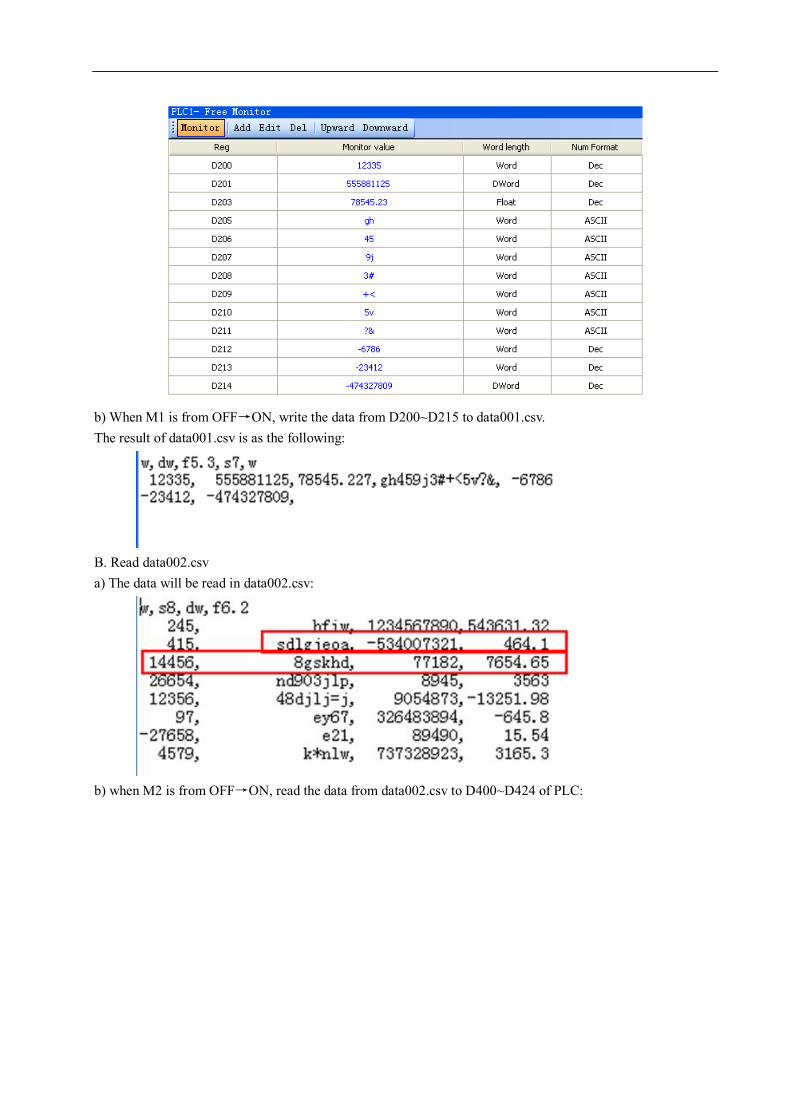
b) When M1 is from OFF→ON, write the data from D200~D215 to data001.csv. The result of data001.csv is as the following:
B. Read data002.csv a) The data will be read in data002.csv:
b) when M2 is from OFF→ON, read the data from data002.csv to D400~D424 of PLC:

C. the process of reading the data from SD card to PLC registers:
D400
space
D401 D402 D403 D404 D405 D406 D407
space space space sd lg je oaS8
D408 D409
-534007321dw
D410 D411
464.1f6.2
D412
14456w
D413
space
D414 D415 D416 D417 D418 D419 D420
space space space space 8g sk hdS8
D421 D422
77182dw
D423 D424
7654.65f6.2

6. Ethernet expansion board XC-TBOX-BD 1. Summarization
2. Characteristics
Flexible distributed automation structure, simplify the system management Standard RJ45 interface, TCP/IP protocol To realize remote monitoring, checking and programming, save time and cost To store and deal with the data via Ethernet, simplify the data processing and filing Connect PLC with Ethernet to realize intercommunication with other devices High cost performance, easy to maintain, support simple user’s friendly diagnose function
3. System construction
The industrial Ethernet system contains XC-TBOX-BD, PC, XC series PLC, XCPpro software, HMI, switch, twisted-pair cable, etc.
4. Suitable field
Industrial Ethernet is an electrical network which based on shielded coaxial cable, twisted-pair cable or optical fiber which based on optical network. It is accord with IEEE802.3 by using ISO and TCP/IP protocol. As the expansion of Modbus/RTU protocol, Modbus/TCP protocol defines the standard of TCP/IP network transmission and application. XC-TBOX-BD meets the requirements for industrial network automation control. It provides complete solution and reliable control method.
The application based on XC-TBOX-BD: Remote monitor, maintain and debug the PLC program of the IP device Traditional Modbus communication is one-master-multi-slaver mode, the speed is very slow.
By using XC-TBOX-BD, master station can communicate with other branch stations. In the following picture, XC-TBOX-BD and TBOX support devices with Modbus/RTU interface
connecting to Ethernet. It can realize multi-master-multi-slaver system; make the devices suitable for complicated system.
Ethernet BD board is used to access to Ethernet, special for XC series PLC
Support Modbus-RTU protocol Suitable for remote monitoring, upload/download, etc XCPpro software version 3.0f and above

Location for install the BD board
5. Interface for Ethernet
Ethernet interface is RJ45, please see the photo on the right: The pin definition of RJ45:
Pin Wire color Signal Direction S1 Orange white TXD+ Output S2 Orange TXD- Output S3 Green white RXD+ Input S4 Blue - - S5 Blue white - - S6 Green RXD- Input S7 Brown white - - S8 Brown - -
6. Install the BD board
Open the cover on the left of PLC, insert the board on the pins, fix it with the screw.
FGCOM
COM X0X1
X2X3
X4X5
X6X7 X15
X16X14X13
X12X11
X10X17
X20X21
PWR
Y
X
PORT1 PORT2
Y15Y14
Y13Y12COM3
Y5Y7
Y6Y11
COM4Y10Y4
Y3COM2Y2
COM1Y1
COM0Y0
AB24V
0V
10 4 532
RUN
ERR
XC3-32R-E
6 7
762 3 540 1

7. Configure the BD board
Install the BD board on the PLC Connect PLC with PC, use XCPpro software to configure the BD board Select configure/BD setting, then click BD serial port:
8. DIP switch
XC-TBOX-BD has four DIP switches: ON
OFF The function of DIP switch:
Switch Status Function S1 ON SLAVE mode
OFF MASTER mode S2 ON Close time log on
OFF Time log on status S3 ON IP address configuration
OFF Use static IP address( 192.168.0.111 ) S4 ON Close DHCP distribution
OFF Use DHCP distribution There are 3 modes to set the IP address: please select the mode via DIP switch A. Use static IP address B. Use DHCP distribution C. Set by users The priority of the 3 modes are A>B>C.
A: use static IP address (S3 ON, S4 random) When using the TBOX-BD at the first time, please use static IP address.
IP address: 192.168.0.111 Subnet mask: 255.255.255.0 Default gateway: 192.168.0.1 Preferred DNS: 192.168.0.1
B: Use DHCP distribution (S3 ON, S4 OFF) DHCP distribution is similar to the IP distribution in PC.
Note: there must be DHCP server in the net. Suggestion: you’d better not use this mode when having condition
1 2 3 4

C : use the address set by users ( S3 ON, S4 OFF ) IP address, subnet mask, default gateway, preferred DNS (the same as default gateway)
9. LED display
LED Name Function ERO Error checking ON: CRC checking error for the data received from serial port(LED is OFF
when the next data are correct) COM Serial port Flicker: connected IP IP address ON: IP address is conflicted LINK Ethernet link ON: network connection is normal ACT Data receiving Flicker: receiving the data
10. Using steps
If you want to connect the PLC in the Ethernet, you have to set the T-BOX-BD first. Please see the steps:
(1) Hardware connection and setting
A Install the XC-TBOX-BD on the PLC. B Make sure the XCPpro version is v3.0f. C Set the DIP switch according to the requirements. D Make sure XC-TBOX-BD is connected with Ethernet. Electrify the PLC. Note: when using XC-TBOX-BD at the first time, please set DIP switch S3 to OFF, make it as static IP
(192.168.0.111), then connect with Ethernet to set parameters. E Make sure PC with XCPpro software are in the network.
(2) Set the parameters
A. Open XCPpro software, double click “communication: COM”
LED

B. Click “+” in the select communication mode window
C. Click “refresh list” to search the XC-TBOX-BD in the network. There are two conditions to edit the XC-TBOX-BD.
(1) Use XC-TOBX-BD at the first time, S3 is OFF, static IP address; the rest parameters are shown as below:
(2) If there is IP address in the XC-TBOX-BD, S3 is ON, the parameters are shown as below:
D. Double click the TBOX in the device list, you can see the parameters of TBOX1 and TBOX4:

Explanation for the parameters:
Configure network
When DIP switch S3 is off, user can set relevant parameters in IP device according to actual using, including IP address、subnet mask、default gateway、preferred DNS(usually the same as default gateway).After settings are finished, set ON the DIP switch S3 to identify other XC-TBOX-BD with static IP in the network.

Remote login in (still developing)
The aim of setting this part of parameters is to connect the XC-TBOX-BD and its device into the WAN, user can maintain the remote devices via the remote login in function. Server 1 and 2: the IP address and port part can be modified according to actually using environment, then
click “write in XC-TBOX-BD” Login part: MAC and password can be used as the user name and password when XC-TBOX-BD is
remote landing, also can be set according to user’s demand(only one combination is the best to prevent from conflicting in the server list) Additionally, when DIP switch S2 is OFF, XC-TBOX-BD is remote timing landing mode which can save the bandwidth of network and T-BOX.
Serial parameters It includes five parts: baud rate、data bit、stop bit and protocol type. Baud rate can be modified but its
numerical value must be consistent with that of connecting device.
Master mode and client mode Under the “edit IP device” dialog box, it will show device type. When XC-TBOX-BD is master mode, it shows “device type: T-BOX_Master”, the parameters setting of “Master” part is effective, “Slave” part is ineffective. When XC-TBOX-BD is slave mode, it shows “device type: T-BOX_Slave”, the parameters setting of “Slave” part is effective and that of “Master” part is ineffective. Device type: XC-TBOX-BD Master It includes three sections: protocol, station number- IP table and shield table. Protocol: UDP: more efficient and faster
TCP: better stability to send and receive data, but occupy more resources Station number-IP table: station number: in Industrical Ethernet, the station number of Slave station IP address: slave station IP address Shield table: for application, when XC-TBOX-BD is Master mode, it can connect with several Modbus
devices with different station numbers by RS485 communication, but only one can be Modbus Master device and others are Modbus Slave devices. Then, list the station numbers of Modbus Slave devices in shield table in order to limit their access authority for XC-TBOX-BD.
Device type: XC-TBOX-BD Slave It includes three sections: send delay (ms), static station number table and shield table. Send delay: as soon as XC-TBOX-BD receives the reply from Slave device, it will send next order at
once. Adding delay time between reply and sending order to reduce the possibility of lose command packets of the slave device.
Static station number table: the station number of Slave device in Industrial Ethernet, supporting direct access
Shield table: in Industrial Ethernet, when Master device access to Slave device by broadcasting mode, in order to limit the access authority of this slave station, write the IP of this slave station into the shield table.
Comment

It contains device name and comment. User can modify them and click OK to confirm. E. Click “Write into T-BOX”, the click “OK”. The devices will be listed in the TCP-IP device window. Close this window. F. It shows “select communication mode” window, please select “UDP” for communication mode, network type can be “outer network” or “inner network”. If there are many XC-TBOX-BD, only the target station works. Now, you can monitor and upload, download program of PLC via Ethernet. G Click “OK” to finish the XC-TBOX-BD parameters setting.
11. Example
The following is a Ethernet consisted of three PLC and one HMI.
In this system, there are 3 XC-TBOX-BD and 1 T-BOX. T-BOX is master mode, others are slave mode.
HMI is master device, PLC1, PLC2, PLC3 are slave devices. This system’s purpose is to control multi slave devices by multi master devices. Make the industrial
network being used widely. The steps are as shown as below:
1) Confirm the station number of the 3 PLC via XCPpro software. 2) Connect TBOX1 and XC-TBOX-BD with related devices. If use TBOX1 and XC-TBOX-BD at the first time, set S3 switch to OFF (static IP address), connect the TBOX1 and XC-TBOX-BD with the Ethernet, configure them with XCPpro software. After finishing the setting for one TBOX, turn on S3 and continue setting next XC-TBOX-BD. (3) Configure the XC-TBOX-BD. Select the BD serial port. (4) Set the IP address: T-BOX1: 192.168.0.1 XC-TBOX-BD2: 192.168.0.2 XC-TBOX-BD3: 192.168.0.3
Ethernet
Master
Slave Slave Slave
HMI
T-BOX1
XC-TBOX-BD2 XC-TBOX-BD3
PLC 1 Station 1
PLC 3 Station 3
PLC 2 Station 2
XC-TBOX-BD4

XC-TBOX-BD4: 192.168.0.4 Please see the edit TBOX device window: T-BOX1 parameters setting:
XC-TBOX-BD 2 parameters setting:

XC-TBOX-BD3 parameters setting:
XC-TBOX-BD4 parameters setting:
Then click write to TBOX. The following steps please refer to “Using step”. Now the TBOX parameters setting are finished.

7. Weighing expansion BD XC-WT-BD
1. Summarization
XC-WT-BD is the expansion BD board of XC series PLC. It can test the 0~39.0625mV voltage signal from pressure sensor, and transform the voltage to digital value.
2. Specifications Analog input DC 0~39.0625mV
Digital output 0~65535
Resolution 0.596uV 0~40mA Transformation speed 20ms/channel
Working ambient No corrosive gas
Ambient temperature 0℃~60℃ Storage temperature -20~70℃ Ambient humidity 5~95%
Storage humidity 5~95%
3. Terminals
Terminal Name Meaning EXC+ Weighing sensor power + EXC+, EXC- connect to weighing sensor power
terminal EXC- Weighing sensor power - SEN+ External reference input +
SEN+, SEN- connect to EXC+, EXC- SEN- External reference input -
Collect one channel pressure sensor signal Test voltage range is 0~39.0625mV 16-bit A/D transformation

SIG+ Weighing sensor signal + SIG+, SIG- connect to sensor signal output terminal
SIG- Weighing sensor signal -
Note: for real application, EXC+ connects to SEN+ and sensor power +, EXC- connects to SEN- and sensor power -. SIG+ connects to sensor output +, SIG- connects to sensor output -.
4. Weighing system A typical weighing system:
The weighing system contains: Loading bearing part: to support the load. Such as flat, hopper, container, air transport car… Pressure sensor: transform the weight to voltage signal. Assembly part: make sure the pressure sensor can work correctly, assembly part and direct part can avoid overload. Overload will cause measurement error and sensor damage. Connection box (JB): to collect several sensor signals. XC-WT-BD: can be used as an electronic assessment device, it gets the pressure sensor signal and makes further assessment.
5. Pressure sensor The pressure sensor is based on resistance strain effect, see the following diagram:
R1 and R2 is strain resistor which make bridge circuit with R3 and R4. With the change of R1 and R2, the bridge circuit will lose the balance, unbalance voltage Uo will be produced as the output of sensor.

U+ and U- are positive and negative point of the sensor power supply. Please select the 5V power of the module or from outside. S+ and S- are positive and negative point of the sensor output. Connect the output to the module to test the weight.
6. A/D transformation diagram The relationship between input voltage and converted digital value:
0~39.0625mV voltage input
7. I/O address XC-WT-BD will not occupy I/O address, the A/D transformed value will be stored in PLC register ID1000.
8. Programming example Suppose the pressure sensor range is 0~100KG (the sensor output voltage range is 0~20.00mV). Display the weight (unit is kG) value in the HMI. Program:
+65535
0 39.0625mV Analog
Digital

D4: real-time weight digital value (float number) D10: the full-range analog value of XC-WT-BD (float number) D14: (the full-range analog value of pressure sensor) ÷ (the full-range analog value of XC-WT-BD) D18: the digital value range of XC-WT-BD (float number) D22: (digital value) ÷ (weight) (float number) D24: the real weight, unit is kG (float number)

Install here
8. Fiber Optical Communication expansion BD XC-OFC-BD
1. Summarization XC-OFC-BD has high baud rate and fast communication speed. The signal is transferred through light wave. Light wave has strong noise immunity ability; the max transmission distance is 1KM. It is easy to build the network, the slave station can up to 254.
2. Installation and wiring (1) Installation Open the left cover of PLC, install the BD board into the pins, fix it with the screws, and close the cover.
Please keep clean for the fiber optical terminal. Please put on the protection cover to prevent pollution.
(2) Wiring
TX:send terminal RX:receive terminal

Connect the TX to RX for all the XC-OFC-BDs, all the PLCs will be a loop.

3. Configuration and settings
(1) BD board settings
Connect the PLC with XC-OFC-BD to the PC, open XCPpro software, choose BD serial port:
(2) Serial port settings
XC-OFC-BD will occupy serial port3 of PLC; it needs to set the port3 in XCPpro software:
(A) The baud rate of all the port3 in the network must be the same.
(B) The station number of all the port3 in the network should be different.
(C) XC3/XC5 support the follow baud rates:
600Hz,1200Hz,2400Hz,4800Hz,9600Hz,19200Hz,38400Hz,57600Hz,115200Hz,192000Hz, 288000Hz, 384000Hz, 576000Hz (D) XC2/XCM/XCC support the follow baud rates: 600Hz,1200Hz,2400Hz,4800Hz,9600Hz,19200Hz,38400Hz,192000Hz,256000Hz,384000Hz, 512000Hz, 768000Hz Please see the settings in XCPpro software:

Please set the suitable parameters, click write to PLC, then download an empty program into the PLC. Finally, re-power on the PLC to make it effective. (make sure to choose serial port3 when setting)

9. Profibus expansion BD board XC-PBOX-BD
1. Summarize XC-PBOX-BD can be the slave station of Profibus DP. It realizes the interconnection between XC series PLC and Profibus DP system.
The theoretical address range of Profibus: 0~127, 127 is broadcast address. Up to 32 master stations can be used. The station amounts can up to 127. The station No. of XC-PBOX-BD should be in the range of 1-255 and in accord with the slave station no.
of Profibus.
2. Terminal resistor Both ends of the Profibus cable should connect terminal resistor. The terminal resistor can clear the signal reflection in the cable which is caused by resistor discontinuity and mismatching.
3. Installation and configuration (1) Open the cover on the left of the PLC, insert the BD into the pins, fix it with the screws and close the cover.
FGCOM
COM X0X1
X2X3
X4X5
X6X7 X15
X16X14X13
X12X11
X10X17
X20X21
PWR
Y
X
PORT1 PORT2
Y15Y14
Y13Y12COM3
Y5Y7
Y6Y11
COM4Y10Y4
Y3COM2Y2
COM1Y1
COM0Y0
AB24V
0V
10 4 532
RUN
ERR
XC3-32R-E
6 7
762 3 540 1
(2) Connect the PLC installed XC-PBOX-BD to the XCPpro software. In the software, click “configure/BD settings”:
Install here
Slave station of Profibus Profibus Modbus Siemens
S7-300
XC-PBOX-BD
Xinje Other devices

1) Choose “BD serial port”:
2) Click “PLC serial port”, choose serial port 3 and modbus num. The modbus num should be the Profibus slave station number. Here it is set to 5 for example.
Click “write to PLC”. Then click download in the software. Finally, please cut the power and power
on again for the PLC and click run .

4. Wiring The port of XC-PBOX-BD is the standard Profibus terminal, please see the terminal definition:
XC-PBOX-BD Profibus DP device
XC-PBOX-BD Profibus DP device
Pin Name
Pin Name 1 2 3 B (RxD/TxD P) 4 5 D-GND GND 6 VP(+) VCC 7 8 A (RxD/TxD N) 9
5—GND and 6—VCC provide power for terminal resistor. If there is no terminal resistor, please do not connect them. Note: Only pin 5, 6, 8, 3 need to be connected.
5. DIP switch Please set the baud rate of communicating between XC-PBOX-BD and Xinje PLC via DIP switch.
Baud rate (bps) DIP1 DIP2 DIP3 DIP4 19200 OFF OFF 9600 OFF ON
38400 ON OFF 115200 ON ON
Note: 1. The default communication parameter is: data bit=8, stop bit=1, even parity. 2. Only DIP switch 1 and 2 are valid, 3 and 4 are invalid.
6. LED There are four LED lights on the XC-PBOX-BD.

D4: the light flashes when reading the station No. of PLC serial port3, it always lights when got the station No. D3: the state of Profibus. D2: it lights when data is being sent. D1: it lights when data is being received.
7. Operation steps Please do the following operations if the master station of XC-PBOX-BD is Siemens Profibus-DP device. Copy XC-PBOX.GSD to the route of \..\Step7\S7data\gsd\ Copy Xinje_B.bmp to the route of \..\Step7\S7data\nsbmp\
If the master station is not Siemens products, please copy XC-PBOX.gsd and Xinje_B.bmp to the folder of gsd and bmp. Now we take Siemens S7-300 series PLC (315-2AH14-0AB0) as an example to explain the debug process. Suppose the S7-300 sets ON M0-M7 of Xinje PLC via XC-PBOX-BD. And set double word register (D0,D1) to 12345678, set (D3,D4) to 87654321. And read the value of M20-27 and (D100, D101)(D102, D103).
(1) Open the Siemens simatic manager software, build a new project. (2) Name the project:
(3) Insert new object/Simatic 300 station, name it as PBOXOPC:

(4) Click PBOXOPC, it will show below window:
(5) Double click the hardware, you will see below window:

(6) Click Insert/insert object, it will show below window:
(7) Click “SIMATIC 300”, then click “RACK-300”, it will show below window:
(8) Click Rail, it will show below window:
(9) Click Option/update catalog, then do the operations in below window:

(10) Choose the matched power module for the PLC. Here we choose PS307 2A , CPU 315-2DP\6ES7
315-2AG10-0AB0\V2.6:
(11) Click v2.6, it will show below window, choose the master station (S7-300) No. of XC-PBOX-BD,
here we choose 2. Then click “New…” button in the window:

(12) Click “Network settings”, set the transmission rate to 12Mbps.
(13) Click , then choose “Profibus DP\ Additional Field Devices\
Gateway\ PBOX”, double click PBOX, then set the slave station No. of PBOX to 5.

(14) As the chapter 1 said, we copy the file XC-PBOX.GSD to \..\Step7\S7data\gsd\, and copy the file Xinje_B.bmp to \..\Step7\S7data\nsbmp\, now we can see the Xinje station picture in the below window:
(15) double click the Xinje station picture, it will show below window. Set the data update mode: At every MD end or At MD scan end.
(16) Configure the read and write. Read: read the value of Xinje PLC to Profibus. Write: write the value of Profibus to Xinje PLC. Force single bit and Set single word: write the value of Profibus to Xinje PLC.

(17) After making the program, click save and compile , then click download to module . Return to
below window:
(18) click “Blocks”, it will show , double click OB1, it will show below window, then click ok to enter
programming window. Then make the program in it.

Programming window:

Program:
(19) After making the program, save and download to the module. Turn On the RUN switch of S7-300. The SF BF LED is OFF on the S7-300, it means the communication is successful. Then turn off the RUN switch. Now please open the XCPpro software, connect it to the Xine PLC with XC-PBOX-BD (please configure the
XC-PBOX-BD at first in the software). Click free monitor , add the data in the monitor list (see figA).
Then turn on RUN switch of S7-300, the monitor data is shown in figB. (M20-M27,D100 D102 are the data write from S7-300 to XC series PLC.

FigA
FigB
(20) Monitor the data of S7-300. Right click the data needs to monitor:

(21) Choose “monitor” to see the data. The data are the same to the setting data in XC series PLC.

(22) Monitor the Read 2 Dwords with the same way:
8. Notes 1. The Xinje PLC only can be slave station with XC-PBOX-BD. XC-PBOX-BD only can be used with Xinje PLC. Please choose the Xinje PLC which can expand BD module. 2. After configuration of the XC-PBOX-BD, please re-power on it. 3. The station No. in the PLC should be accord to the Profibus slave station No., especially for SCADA application.

信捷科技电子有限公司
江苏省无锡市蠡园开发区
创意产业园 7 号楼四楼
邮编: 214072
电话: (0510)85134136
传真: (0510)85111290
Xinje Electronic Co., Ltd.
4th Floor Building 7,Orignality Industry
park, Liyuan Development Zone, Wuxi
City, Jiangsu Province 214072
Tel: (510)85134136
Fax: (510)85111290