operationmanualbinacontrol.co.id/_upload/lampiran2/busbar-machinejpmx.pdf · 2018-04-24 · 7...
TRANSCRIPT

Web:www.busbarmachine.net Telephone:86+531-88605317 86+531-88772346 Fax:86+531-88772566
1
Operation Manual
Model NO.:JPMX-303ESK
NAME:Busbar Processing Machine
Jinan JingPeng CNC Machinery Co.,Ltd

2
CatalogⅠ. Introduction........................................................................................................................................................ 3Ⅱ. The profile of machine....................................................................................................................................... 4Ⅲ. Basic Parameters................................................................................................................................................ 4Ⅳ. Application and features.....................................................................................................................................5Ⅴ. Structure and working principle of the machine................................................................................................5Ⅵ. Installation and considerations before start-up.................................................................................................. 6Ⅶ. How to operate each unit....................................................................................................................................6Ⅸ. Hydraulic System............................................................................................................................................... 9Ⅹ. The operation and electric control principle.................................................................................................... 11Ⅺ. Maintainance.................................................................................................................................................... 13

3
Ⅰ. IntroductionGeneral Safety RegulationsBefore Starting
1. Make sure a safety work surrounding around the machine.2. Don’t dress a scarf or an overcoat when launching the machine, so as not to endanger personal safety.3. Required power supply: three phases four wires system, 380V±10%+N.4. Keep the machine idling running for 5 minutes after start up when the operating temperature below 5
degree Celsius.5. Must read the operating manual carefully, be familiar with the structure, performance of the equipment and
the operation mode of each work station.
In Operation
1.Installations, commissioning (mold calibration, blade inter space adjustment) ormold dis-assembly must be operated by skilled workers according to the operation instruction strictly.2.When the machine running, never put your hands or body between the upper and lower mold (blade), in orderto avoid accidents.3. Do not put any debris or tools on the table, in order to avoid rolling into the mold or blade and cause anaccident.
4. The machine can be operated by several staffs, so there must be a specialist who shall be responsible for thedirecting of the production.
5. Be sure to choose the blade and punching gap and bending radius according to the thickness of the cooper oraluminum busbar.
6. Be sure to stop the machine when change the mold, in order to avoid danger.7. Be carefully when holding the work-piece to wait the mold slider downward.8. Check the cutting edge of the blade regularly, grinding or change the blunt blade timely.9. Keep hydraulic oil clean and flow unobstructed, the hydraulic oil in the oil tank is recycling and do not loss.
Each shift shall add oil to each working unit of the machine respectively.10.Electrical and hydraulic components must ensure flexibility and movement in the correct position. Do stopand check the machine when it works abnormally.
After the Operation
The different positions must be shut off in a proper order as below.1. Shut off the buttons of each unit.2. Shut off the power switch on the operation panel.3. Shut off the air switch on the main power circuit.4. Shut off the switch of the power supply.
Note: The operators must operate the machine according to this manual instruction.we are not responsible for any consequences caused by the non-proper operation which are violated to thismanual instruction.
4
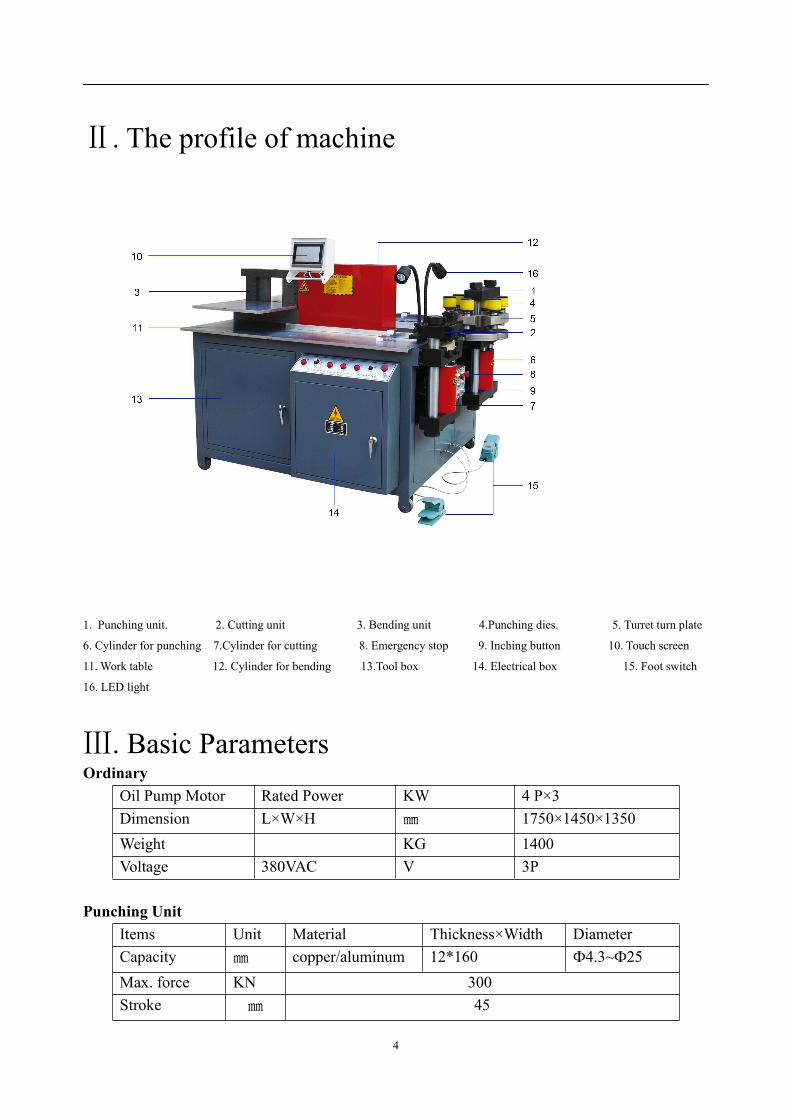
Ⅱ. The profile of machine
1. Punching unit. 2. Cutting unit 3. Bending unit 4.Punching dies. 5. Turret turn plate
6. Cylinder for punching 7.Cylinder for cutting 8. Emergency stop 9. Inching button 10. Touch screen
11. Work table 12. Cylinder for bending 13.Tool box 14. Electrical box 15. Foot switch
16. LED light
Ⅲ. Basic ParametersOrdinary
Oil Pump Motor Rated Power KW 4 P×3Dimension L×W×H ㎜ 1750×1450×1350Weight KG 1400Voltage 380VAC V 3P
Punching UnitItems Unit Material Thickness×Width DiameterCapacity ㎜ copper/aluminum 12*160 Ф4.3~Ф25Max. force KN 300Stroke ㎜ 45

5
Cutting UnitItems Unit Material Thickness WidthCapacity ㎜ copper/aluminum 12 160Stroke ㎜ 45
Bending UintItems Unit Material Thickness WidthCapacity ㎜ copper/aluminum 12 160Max. force KN 300Stroke ㎜ 200
Ⅳ. Application and featuresThis machine is mainly used for processing copper busbar and aluminum busbar, which can be processed
(punching, cutting and bending) so long as placed on the relevant working unit. This machine is used forefficient busbar manufacturing in the industries of high and low voltage electric appliances, provide thecompetitive edge for our global customers.
Features:1. The machine is equipped with punching, cutting/shearing, bending three processing units and can do
busbar punching, shearing, bending processing, respectively. This machine can significantly improveproduction efficiency than conventional busbar processing equipment, and also significantly improves theease of use.
2. The working unit can be easily adjusted (stroke within certain limits), so you can reduce processing time,enhances the production efficiency.3. Multi-purpose processing can be achieved by changing the mold, such as fold-bending, folding vertical
bending, embossing, twisting twist, voltage cable joints and back pressure etc.4. The machine is equipped with a manual buttons and foot switch two modes of operation, It is simply
operated, easy to use. General skilled workers can operate the it easily.
Ⅴ. Structure and working principle of the machineThis machine consists of machine rack, punching, shearing, bending unit, hydraulic station, electrical
systems and components, such as mold.Rack consists of square steel tubes welded together, which is with enough strength and rigidity. Punching,
shearing, bending and electrical appliances are installed on the rack, hydraulic station in the rack.
The working principle is as follows:The motor (to provide power to the pump) → pump (generate high pressure fluid power) →
electromagnetic relief valve (control pressure) → solenoid valve (pressure oil to be delivered to each cylinder)→ oil cylinder (cylinder movement, achieving punching, shearing, bending and processing).Motors passes power to the oil pump, oil pump generates high pressure oil. High pressure hydraulic oil througha one-way valve into the electromagnetic relief valve. Hydraulic oil (through the overflow valve) flow back

6
into the tank. Electromagnetic relief valve is closed and it generates terminal pressure, oil is then transported tothe solenoid valve, solenoid valves control the direction of hydraulic oil, make up and down or back and forthmotion of the cylinder.
Ⅵ. Installation and considerations before start-upMachine installation:
1. If lifting is required when the machine in the transportation and installation, please use forklift andacross the machine from the bottom.
2. The machine should be installed on a firm, flat surface.3. The machine must be installed on a spacious processing area to meet the working conditions of the
machine.4. The power wire must be well connected, do not interfere with the work.5. The machine use a three-phase four-wire power 380VAV+N.6. Before you start this machine, please refill with 80 liters No. 46 anti-wear hydraulic oil. ( No.46
means kinematic viscosity)
Precautions before start-up1. Make sure the rotation direction of the motor is the same as the pump rotation. If not, please change the
phase sequence (make an exchange of any two phases)2. If the Working ambient temperature is under 5 ℃ (Celsius), the pump need 5 minutes idling running before
working.3. During the working, if the oil temperature reaches 55 ℃ (Celsius) or higher, the oil additive will make
chemical change and dissolved, therefore, resulting in failure of the valve or pump. Working under hightemperatures will shorten the life of the seals and then cause oil leaks. Therefore, the operators should stopthe machine when the oil temperature reaches or more than 55℃. There is a thermometer on the oil tank.
4. Make sure each device is absolutely clean. The sliding parts will stand large friction, so the device need tobe well lubricated to guarantee smooth working under up and down or back and forth movement.
5. The M16 bolt for fixed cylinder will loosen when they are under too much pressure,so the operator shouldcheck the bolt regularly (recommend: check every month), and tight them carefully.
Ⅶ. How to operate each unitPunching units1. Before punching, you have to lubricate the moving parts of the machine.2. When punching, the busbar shall be placed steady, in order to be punched smoothly.3. Punching device can withstand greater forces directly, but when subjected to eccentric loading, may causedies malfunction. (Prohibit the use of round dies punch oval holes, in case it cause physical harm and diesdamage)4. Note: defects in materials such as copper and aluminum busbar can also cause mold damage.5. After punching, take out the busbar after the upper punch dies rise top.6. When punching, pick the right dies.
(Note: upper and lower dies should be consistent, there is size mark on the upper and lower dies.)7. Checking the stroke of upper dies before punching, make sure upper dies touched the lower dies and notpunch. ( The limited switch shows in below picture in red blank)

7
How to replace the punching dies1. First, select the appropriate dies location (turret punch, 6 location), separate the upper and lower dies,
finding the right location and set in the selected upper dies.2. Carry out the lower dies, then put another lower dies matched with the upper dies, and then lightly rotate
the new installed dies station make it under the beam, insert the positioning needle.3. Be sure to use "button" or "foot switch" check upper and lower mold centering.
Note: The punching range of the punching dies:5mm punching dies can punch busbars thickness no more than 5mm.7mm punching dies can punch busbars thickness no more than 6mm.9mm punching dies can punch busbars thickness no more than 8mm.11mm punching dies can punch busbars thickness no more than 12mm.13mm punching dies can punch busbars thickness no more than 16mm.
How to use cutting unit1. Observe the actual cut size by the use of observation hole of the upper and lower blades.2. Accurate and continuous shearing can be down by adjusting the stroke switch.3. The use of fastening bolt can prevent the cut material from tilting, which can reduce the abrasion of blades
and improve processing quality of the sections.4. Shear unit can cut 3~12 mm thick, width of 160 mm copper (Al) busbar.5. when the cutting work does not perform well, be sure to check the blade and the cutting gap.
How to adjust cutting blades gap1. Overlapping the upper blade and the lower blade by inching move, press down the emergency stop button,
and be caution.2. Release the upper blade carrier pin on both sides, slightly loosen the fastening screws, move back and forth
to adjust the gap by adjusting the upper blade carrier.3. Make the upper and lower blades maintain contact under the state of motionless, insert the corresponding
thickness feeler gauge between the two blades, tighten the adjustment screws (always check the screwsagainst loosening). Feeler gauge thickness (gap) relationship with cut Busbar thickness as the followingtable:

8
Busbar Thickness(㎜) 3-6 6-12
feeler gauge Thickness(㎜) 0.10 0.15
1. Insert the pin and tighten the screws when the machine in a halt state.2. Switch on the power, by raising or lowering the guide plate to check the gap.3. Before cutting, you have to lubricated the moving parts of the machine.
How to use bending unitWhen bending, you should follow the following method:1. Moving parts should be lubricated.2. When doing the bending, please select the right dies according to the width and thickness of the busbars.
The L80 bending dies for bending busbars thickness of 8-12mm.The L40 bending dies for bending busbars thickness of 2-6mm.There is number mark on the bending dies.
3. Details for CNC controlled bending operation, please see the CNC system operation instructions4. Optional dies which can increase other functions:(1) Horizontal bending dies: operator replaces vertical bending dies, put busbar into the middle opening of the
convex molds, fastening the bolt at the top and outside of the convex mold, make sure inch moving at first,to get the desired angle. If a batch of products needs to be processed, the detecting block can be adjusted tothe position reached in the first stroke.
(2) Embossing: replace embossing mold, this function can be realized. Note that puts busbar in the middle ofthe embossing molds.
9
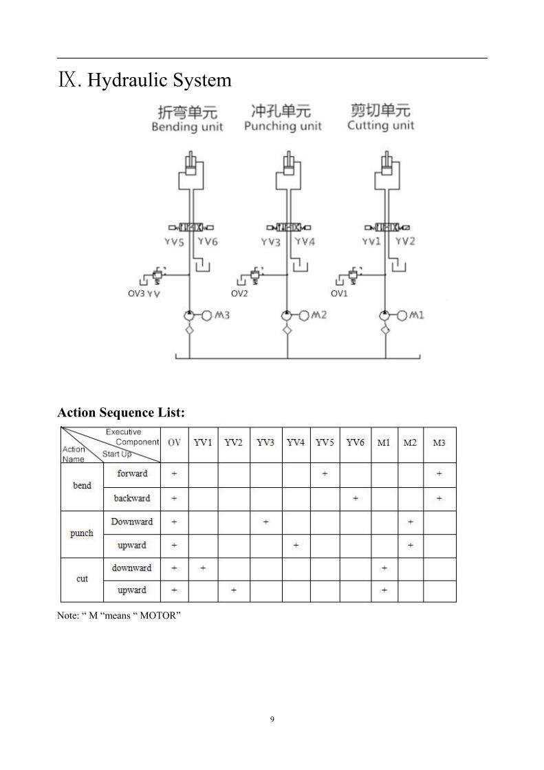
Ⅸ. Hydraulic System
Action Sequence List:
Note: “ M “means “ MOTOR”
10
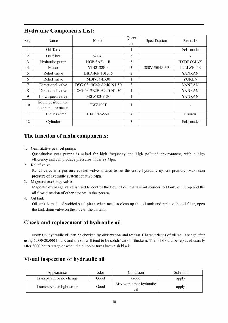
Hydraulic Components List:Seq. Name Model
Quantity
Specification Remarks
1 Oil Tank - 1 Self-made2 Oil filter WU40 3 -3 Hydraulic pump HGP-3AF-11R 3 HYDROMAX4 Motor YJB2132S-4 3 380V-50HZ-3P JULIWEITE5 Relief valve DBDH6P-101315 2 YANRAN6 Relief valve MBP-03-H-30 1 YUKEN7 Directional valve DSG-03--3C60-A240-N1-50 3 YANRAN8 Directional valve DSG-03-2B2B-A240-N1-50 1 YANRAN9 Flow speed valve MSW-03-Y-30 1 YANRAN
10liquid position andtemperature meter
TWZ100T 1 -
11 Limit switch LJA12M-5N1 4 Caoren
12 Cylinder - 3 Self-made
The function of main components:
1. Quantitative gear oil pumpsQuantitative gear pumps is suited for high frequency and high polluted environment, with a highefficiency and can produce pressures under 28 Mpa.
2. Relief valveRelief valve is a pressure control valve is used to set the entire hydraulic system pressure. Maximumpressure of hydraulic system set at 28 Mpa.
3. Magnetic exchange valveMagnetic exchange valve is used to control the flow of oil, that are oil sources, oil tank, oil pump and theoil flow direction of other devices in the system.
4. Oil tankOil tank is made of welded steel plate, when need to clean up the oil tank and replace the oil filter, openthe tank drain valve on the side of the oil tank.
Check and replacement of hydraulic oil
Normally hydraulic oil can be checked by observation and testing. Characteristics of oil will change afterusing 5,000-20,000 hours, and the oil will tend to be solidification (thicken). The oil should be replaced usuallyafter 2000 hours usage or when the oil color turns brownish black.
Visual inspection of hydraulic oil
Appearance odor Condition SolutionTransparent or no change Good Good apply
Transparent or light color GoodMix with other hydraulic
oilapply

11
A little bit change Good Has bubble or water Separate the waterChanged to brownish black Not good Being Oxidized or heated replace
Transparent and little impurities Good External stuff Using after filtered
Add hydraulic oil when the fluid level is too low, Recommend using N46 anti wear hydraulic oil
Ⅹ. The operation and electric control principle
Introduction
1. Electrical SpecificationPower supply: three-phase four-wire 380V±10%+NRated capacity: 12KVAControl voltage:220V(AC)、50HZ
2. Machine operators must read this manual carefully before operating this machine, understand operationsteps and be familiar with switches and LEDs for each button function and meaning.
3. The three working procedure can be operated independently, it is also the distinctive advantages of thismachine.
Operation
1. Power on(1) Switch on the circuit breaker in the electrical box.(2) Switch on the key switch of " ON/OFF ", and the control power supply is switched on. At this point the
"power" led on the main panel is lit.
2. Punching unit(1) Press down the "Punching" button on the main control panel, the motor for punching unit will be started,
then the "punching" indicator lights.(When the power switched on, should pay attention to the motorturning direction, two of the three phases should be exchanged if turning direction of the motor is wrong,then the motor will reverse rotation).
(2) Step on the punching unit foot switch or the inching button, punch die will go downward until the sensor(shown in below picture)reach the bottom dead center, punch die returns to the top dead line. If releasing thefoot switch or the inching button in the process of the punch die going downward, the punch dies will bestopped. When you step on the foot switch or the inching buttons, punch die continues downward, if the"upward" button on the panel of punching unit is pressed down, punch die will be stopped when the sensorreaches top dead line.

12
(The blank steel strip is the sensor, the two blue part is the limit switches, they are on bottom left of the punching cylinder )3. Cutting/Shearing Unit(1) Press down the “cutting” button on the main control panel, the motor for cutting unit will be started,
cutting indicator is lit. (When the power switched on, should pay attention to the motor turning direction,two of the three phases should be exchanged if turning direction of the motor is wrong, then the motor willreverse rotation).
(2) Step on the foot switch of cutting unit or the inching button, the cutting blade will slide downward, until ithits the bottom dead point switch, then returns to top dead center. If the foot switch or the relevant buttonis released, the slider will stop. When you step on the foot switch or the relevant button at this point again,slider keeps going down. If the "upward" button on the panel of cutting unit is pressed down, the sliderwill be stopped when it reaches the top dead center.
4. Bending unit(1) Press down the “Bending” button on the main control panel, at this point the motor for bending unit will bestarted and the indicator of the" bending " button lights.(When the power switched on, should pay attention to the motor turning direction, two of the three phasesshould be exchanged if turning direction of the motor is wrong, then the motor will reverse rotation).(2) Step on the bending unit foot switch or the inching buttons, the slider will move on until it meets the frontdead center switch and returns to its original state. The slider will stop if releasing the foot switch or the inchingbuttons in the process of bending. When you step on the foot switch or press the appropriate button at this pointagain, the slider will move on; if you press the "backward" button on the bending unit panel, the slider will goback to its original state and stop.
5. Automatic work for bending unitDetails for CNC controlled bending operation, please see the CNC system operation instructionsElectrical maintenance and precautions:Electrical cabinet dust should be cleaned periodically, keep it clean, air injection or erasing method is
available. Always check and ensure that all connections fixed, screw fastened, among the various componentsof the connection terminal is locked in order to prevent poor contact, resulting in malfunction or failure.Ensures the curvature of the cable, in case of wire break.

13
Ⅺ. Maintenance1. Common malfunction and removal1. Power supply no powerCheck that the fuse is burned out or not, replace with a new one if it burned out.
2. The power supply has power, but the motor is not working.Check that the motor is overloaded or not, adjust the load to the normal state if overloaded.
3. Even if the power supply has power, the motor works, but the machine does not start, and made a lot ofnoise.Checking motor rotation direction is right or not, stroke switch is released or not, and the relay is loose or not.4. The motor turns correctly, but the whole operation is not implementedCheck the relay, proximity switches, solenoid valves, relief valves.
5. One unit does not work, but the load has been added to the solenoid valveCheck the limit and solenoid valves.
6. Upward/Downward operation of the machine fails, the pressure can only be added to one direction.Check the limit and solenoid valves.
7. The machine is not working properlyCheck the overflow valve or replacing a bad contact relay.
8. Oil Cylinder quickly downward, but not upwardContact solenoid valves, repair or replace the cylinder.
9. The oil cylinder stops working after rising and descendingCheck the limit switch.
10. After the rising or falling of the oil tank (with pressure), the machine can't stopCheck the limit switch.
11.Without pressure or pressure of the machine never gets promoted.Check the solenoid valves associated with the relief valve is working properly or not, manual valve is stuck
or not, check the overflow valve is stuck or not, remove it and clean it if necessary.
2. lubrication
The moving parts shall be lubricated before starting up in every working shift.The moving parts are marked in below pictures by red circles.1. Punching parts

14
2. Cutting/shearing parts
3. Bending parts