opera tm - nhsggc · 5 before using your opera, familiarise yourself with the various parts and...
TRANSCRIPT
Operating and Product Care Instructions
TM
KKX 52180.GB/2 Aug 2000
KPX 01700.GBIssue 1
Jan. 2001
Opera

2
The vertical and horizontal lines printed in themargins adjacent to the text/illustrations in theseinstructions are for ARJO use only and should bedisregarded by the reader.Some of the information contained in theseinstructions may become outdated, due toimprovements made to the product in the future. Ifyou have any questions regarding these instructionsor your lifter, please contact ARJO or theirapproved distributor.
The policy of ARJO is one of continuousdevelopment, and therefore reserve the right tochange specifications without notice.ARJO strongly advise and warn that only ARJOCompany Designated Parts, which are designed forthe purpose, should be used on equipment andother appliances supplied by ARJO, to avoidinjuries attributable to the use of inadequate parts.
The ARJO Company’s Conditions of sale makespecific provision confirming no liability in suchcircumstances.‘Opera’, ‘Flites’ and ‘Lock and Load’ are trademarks of the ARJO Group
3
SECTION Page No.
Foreword ..................................................... 4Safety Instructions ...................................... 5Product description/function ..................... 6-12
Parts referred to in this manual ................. 6-7Slings ......................................................... 8-9Control Handset......................................... 10Dual Control panel .................................... 10Emergency stop button (red) ..................... 10Reset button (green) .................................. 10System failure lower override ................... 11System failure wind down facility ............ 11System cut-out switch ............................... 11Automatic cutout ....................................... 12Automatic stop function ............................ 12Battery discharge indicator........................ 12Service indicator........................................ 12Adjustable width chassis legs.................... 12Chassis castor Brakes ................................ 12
Using your Opera ........................................ 13-28Before apparoaching the patient................ 13Powered opening ‘v’ chassis ..................... 13“Lock and Load” system jib...................... 13Using the 4 point spreader bar................... 13
To lift from a chair ................................. 14To lift from a bed ................................... 15To lift from the floor .............................. 17At the toilet ............................................ 18
Powered patient positioning spreader bar(if fitted) .................................................... 19Using the 2 point spreader bar................... 21
To lift from a chair ................................. 21To lift from a bed ................................... 22
Using the soft stretcher.............................. 23Using the strap stretcher ............................ 25Patient Scale (if fitted)............................... 28
Lifter Battery charging .............................. 29-30Warnings for charging ............................... 29General safety Practices for Batteries ....... 29
Care of your Opera ..................................... 31-33Sling Care and Cleaning............................ 31Lifter Care and Cleaning ........................... 31Periodic Testing......................................... 32Service Advice .......................................... 32
Labels ........................................................... 34Technical Specification ............................... 35-36
Lifter Dimensions...................................... 37
Contents
4
Thank you for purchasing ARJO equipmentYour Opera is part of a series of quality productsdesigned especially for hospitals, nursing homesand other health care uses.We are dedicated to serving your needs andproviding the best products available along withtraining that will bring your staff maximum benefitfrom every ARJO product.Please contact us if you have any questions aboutthe operation or maintenance of your ARJOequipment.The touch panel label on the dual control paneldisplays several instruction symbols. The letter (i)shown on the open book icon indicates‘information’, and is an instruction to always readthe operating instructions before use. (See fig 1).The expected operational life of the Opera is 10years, providing it has been regularly serviced andmaintained as recommended in these instructions.The expected operational life of the consumableparts e.g. batteries, slings etc.is dependent on usage(see also ‘Care of Your Opera’ section).All references to the patient in these instructionsrefer to the person being lifted, and reference to theattendant refer to the person who operates the lifter.References to left and right of the lifter in theseinstructions are as viewed from the rear of theOpera, i.e. viewed from the dual control panel (seeFig. 1)Lifting operations in these instructions aredescribed as if lifting a patient from a chair, thesame operations can be performed effectively whenlifting a patient from a wheelchair or sittingposition on a bed, although a second attendantshould support the patient if the patient lacks sittingbalance.All operations in these instructions are described asif the attendant were using the control handset.Each operation described can be controlled usingthe control handset and/or the dual switch panel,situated at the rear of the mast.
Foreword
5
Before using your Opera, familiarise yourself withthe various parts and controls as illustrated in Fig.1, and other illustrations, then please read thismanual thoroughly in its entirety before using yourOpera. Information in the manual is crucial to theproper operation and maintenance of theequipment, and will help protect your product andensure that the equipment performs to yoursatisfaction. Some of the information in thisbooklet is important for your safety and must beread and understood to help prevent possible injury.If there is anything in the manual that is confusingor difficult to understand, please call ARJO Ltd ortheir appointed distributor (the telephone numberappears on the last page of this manual.Symbols used adjacent to the text in theseinstructions:-
This product has been designed and manufacturedto provide you with trouble free use, however, thisproduct does contain components that with regularuse are subject to wear.
See also “Care of your Opera” section. This product is intended to be operated entirely byan attendant. No functions regarding the control ofthis product should be performed by the patient. Asecond attendant may be required with certainpatients.
Danger: Means:- electrical hazardwarning, failure to understand and obeythis warning may result in electricalshock.
Warning: Means:- failure to understandand obey this warning may result ininjury to you or to others.
Caution: Means:- failure to followthese instructions may cause damage toall or parts of the system or equipment.
• Note: Means:- this is important information for the correct use of this system or equipment.
Warning: SOME OF THESE PARTSARE SAFETY CRITICAL TO THEOPERATION OF THE LIFTER ANDWILL NEED EXAMINING ANDSERVICING ON A REGULAR BASISAND MUST BE REPLACED WHENNECESSARY.
Warning: Use only ARJO slings andstretchers that have been specificallydesigned for the Opera.
Warning: Do not overload the Operabeyond the approved lifting capacity ofthe lowest rated attachment/accessory.The Opera may be used on gentle slopeswith caution.Care should be taken when manuallylifting alternative/optional componentse.g. stretcher frames, spreader bars etc., toavoid injuryDo not attempt to manually lift thecomplete lifter.
Caution: Although manufactured to ahigh standard the Opera and accessoriesshould not be left for extended periods inhumid or wet areas.Do not under any circumstances spray theOpera or accessories (excluding slings orARJO approved wet environmentequipment) with water e.g. under theshower.
Warning: It is advisable to familiariseyourself and understand the operation ofthe various controls and features of theOpera and ensure that any action or checkspecified is carried out beforecommencing to lift a patient.
Warning: The ARJO Opera has beendesigned as a mobile lifter for raising andtransporting patients in hospitals and carefacility environments, and should only beused for this purpose.The ARJO Opera can be supplied with avariety of optional attachments, whichmay not be described in these instructions.If your Opera has been fitted with analternative/optional sub assembly e.g:stretcher etc.: then always refer to theseparate relevant operating instructionssupplement, as well as these instructions,before attempting to operate the lifter.
Safety Instructions
6
Fig. 1
1
2
3
45
6
7
8
9
10
1112
13
14
1516
1718
2019
21
22
23
24
P138
9ab,
P13
91c,
P11
98a,
P13
91c,
P13
95e,
P13
96c,
mP1
142c
Product Description/Function
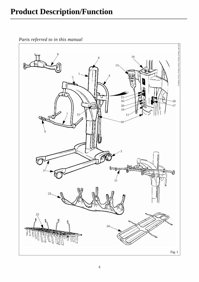
Parts referred to in this manual

7
Fig. 1 Key1. Mast2. Adjustable chassis legs3. Braked castors4. Lifter manoeuvring handle5. Jib6. Mast top cover7. 4 Point spreader bar8. 2 Point spreader bar (if supplied)9. Patient positioning handle10. Lifter battery pack11. Battery release button12. Patient scale (if fitted)13. Control handset14. Dual control panel15. Emergency stop button16. Reset button17. System failure lower override18. System cut-out switch19. Battery discharge indicator20. Service indicator21. Stretcher frame (if supplied)22. Soft stretcher (if supplied)23. Strap stretcher (if supplied)24. Scoop stretcher (if supplied)
Product Description/Function
8
Slings
A circular label is fitted to the lifter jib for quickcolour to size reference (see “Labels” section).A range of special purpose slings are available asaccessories, for these or for special size slings,contact your ARJO representative.
• Note: All Opera slings will support 190kg/420lbs), note: the extra extra large sling will support 200 kg (440 lbs) all slings are coded for size by having different coloured edge binding as follows:Brown - Extra small - XSRed - Small - SYellow - Medium - MGreen - Large - LBlue - Extra Large - XLWhite - Extra Extra Large
Warning: Only use ARJO suppliedslings and stretchers that are designed tobe used with Opera. The sling profilesillustrated (see fig. 2) will help to identifythe various ARJO slings and fabricstretchers available.If ARJO Flites (disposable slings) are tobe used with the Opera, then always referto the separate operating instructions forARJO Flites, (literature reference part No.MAX01720), as well as these instructionsbefore using.
Warning: ARJO slings with headsupport have two pockets at the headsection which should contain plasticreinforcement pieces during use. Alwaysensure these reinforcement pieces havebeen inserted into the sling pockets beforeusing the sling.
Product Description/Function

9
Four point unpadded slingFour point padded sling Four point mesh sling
Four point amputee slingLoop sling (with headrest)Four point toiletting sling (With headrest)
Loop slingSoft stretcher
Fig. 2
P139
0, P
1143
a,b
, P95
3 a,
b, c
, d, e
Product Description/Function
ARJO standard sling profiles that can be used with the opera
10
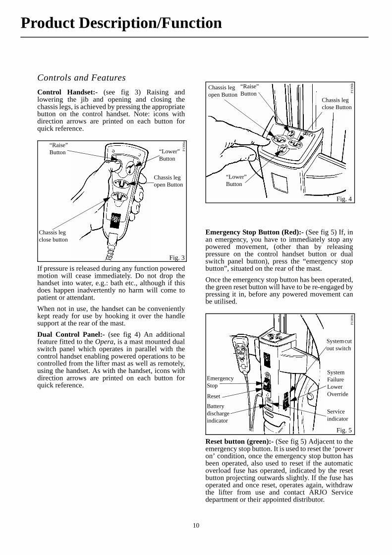
Controls and FeaturesControl Handset:- (see fig 3) Raising andlowering the jib and opening and closing thechassis legs, is achieved by pressing the appropriatebutton on the control handset. Note: icons withdirection arrows are printed on each button forquick reference.
If pressure is released during any function poweredmotion will cease immediately. Do not drop thehandset into water, e.g.: bath etc., although if thisdoes happen inadvertently no harm will come topatient or attendant.When not in use, the handset can be convenientlykept ready for use by hooking it over the handlesupport at the rear of the mast. Dual Control Panel:- (see fig 4) An additionalfeature fitted to the Opera, is a mast mounted dualswitch panel which operates in parallel with thecontrol handset enabling powered operations to becontrolled from the lifter mast as well as remotely,using the handset. As with the handset, icons withdirection arrows are printed on each button forquick reference.
Emergency Stop Button (Red):- (See fig 5) If, inan emergency, you have to immediately stop anypowered movement, (other than by releasingpressure on the control handset button or dualswitch panel button), press the “emergency stopbutton”, situated on the rear of the mast.Once the emergency stop button has been operated,the green reset button will have to be re-engaged bypressing it in, before any powered movement canbe utilised.
Reset button (green):- (See fig 5) Adjacent to theemergency stop button. It is used to reset the ‘poweron’ condition, once the emergency stop button hasbeen operated, also used to reset if the automaticoverload fuse has operated, indicated by the resetbutton projecting outwards slightly. If the fuse hasoperated and once reset, operates again, withdrawthe lifter from use and contact ARJO Servicedepartment or their appointed distributor.
P139
6a
Fig. 3
“Raise” Button “Lower”
Button
Chassis leg open Button
Chassis leg close button
Fig. 4
P139
6b“Raise” Button
“Lower” Button
Chassis leg open Button
Chassis leg close Button
Fig. 5
P138
9b
Emergency Stop
Reset
System Failure Lower Override
System cut out switch
Battery discharge indicator
Service indicator
Product Description/Function
11
System Failure Lower Override:- (See fig 5) Thiscan be used in the event of main control failure. Inthe unlikely event that the control handset or dualswitch panel fails to operate the lifter, with a patientstill supported by the sling or stretcher, provisionfor lowering has been made, using the “SystemFailure Lower Override switch”, situated on theright hand side of the controls console, a green andwhite identification label is positioned near theswitch, for quick and easy recognition. If pressureis released from the switch during use, loweringwill stop.
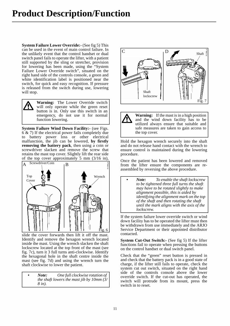
System Failure Wind Down Facility:- (see Figs.6 & 7) If the electrical power fails completely dueto battery power loss or other electricalmalfunction, the jib can be lowered, by firstlyremoving the battery pack, then using a coin orscrewdriver slacken and remove the screw thatretains the mast top cover. Slightly lift the rear sideof the top cover approximately 5 mm (3/16 in),
slide the cover forwards then lift it off the mast.Identify and remove the hexagon wrench locatedinside the mast. Using the wrench slacken the shaftlockscrew located at the top front of the mast (seefig. 7c), turn it 3 full turns anti-clockwise. Identifythe hexagonal hole in the shaft centre inside themast (see fig. 7d) and using the wrench turn theshaft clockwise to lower the patient.
Hold the hexagon wrench securely into the shaftand do not release hand contact with the wrench toensure control is maintained during the loweringprocedure.Once the patient has been lowered and removedfrom the lifter ensure the components are re-assembled by reversing the above procedure.
If the system failure lower override switch or winddown facility has to be operated the lifter must thenbe withdrawn from use immediately and the ARJOService Department or their appointed distributorcontacted.System Cut-Out Switch:- (See fig 5) If the lifterfunctions fail to operate when pressing the buttonson the control handset or dual switch panel.Check that the “green” reset button is pressed inand check that the battery pack is in a good state ofcharge, if the lifter still fails to operate, check thesystem cut out switch, situated on the right handside of the controls console above the loweroverride switch. If the cut-out has operated, theswitch will protrude from its mount, press theswitch in to reset.
Warning: The Lower Override switchwill only operate while the green resetbutton is in. Only use this switch in anemergency, do not use it for normalfunction lowering.
Fig. 6
P139
8a,bA B
TopCover
Wrench
Screwdriver/Coin
• Note: One full clockwise rotation of the shaft lowers the mast jib by 10mm (3/8 in).
Fig. 7
P139
8c,dC D
Shaft lockscrew
Shaft
Warning: If the mast is in a high positionand the wind down facility has to beutilized always ensure that suitable andsafe measures are taken to gain access tothe top cover.
• Note: To enable the shaft lockscrew to be tightened three full turns the shaft may have to be rotated slightly to make alignment possible, this is aided by identifying the alignment mark on the top of the shaft and then rotating the shaft until the mark aligns with the axis of the lockscrew.
Product Description/Function
12
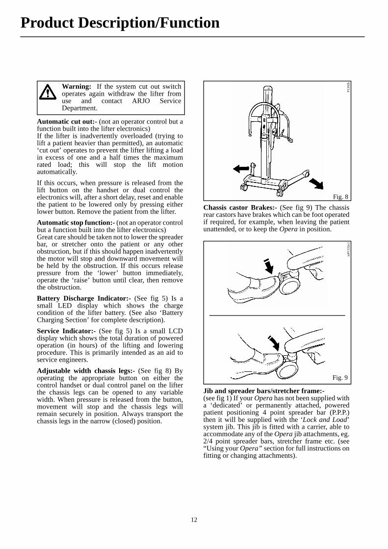
Automatic cut out:- (not an operator control but afunction built into the lifter electronics)If the lifter is inadvertently overloaded (trying tolift a patient heavier than permitted), an automatic‘cut out’ operates to prevent the lifter lifting a loadin excess of one and a half times the maximumrated load; this will stop the lift motionautomatically.If this occurs, when pressure is released from thelift button on the handset or dual control theelectronics will, after a short delay, reset and enablethe patient to be lowered only by pressing eitherlower button. Remove the patient from the lifter.Automatic stop function:- (not an operator controlbut a function built into the lifter electronics)Great care should be taken not to lower the spreaderbar, or stretcher onto the patient or any otherobstruction, but if this should happen inadvertentlythe motor will stop and downward movement willbe held by the obstruction. If this occurs releasepressure from the ‘lower’ button immediately,operate the ‘raise’ button until clear, then removethe obstruction.Battery Discharge Indicator:- (See fig 5) Is asmall LED display which shows the chargecondition of the lifter battery. (See also ‘BatteryCharging Section’ for complete description).Service Indicator:- (See fig 5) Is a small LCDdisplay which shows the total duration of poweredoperation (in hours) of the lifting and loweringprocedure. This is primarily intended as an aid toservice engineers.Adjustable width chassis legs:- (See fig 8) Byoperating the appropriate button on either thecontrol handset or dual control panel on the lifterthe chassis legs can be opened to any variablewidth. When pressure is released from the button,movement will stop and the chassis legs willremain securely in position. Always transport thechassis legs in the narrow (closed) position.
Chassis castor Brakes:- (See fig 9) The chassisrear castors have brakes which can be foot operatedif required, for example, when leaving the patientunattended, or to keep the Opera in position.
Jib and spreader bars/stretcher frame:-(see fig 1) If your Opera has not been supplied witha ‘dedicated’ or permanently attached, poweredpatient positioning 4 point spreader bar (P.P.P.)then it will be supplied with the ‘Lock and Load’system jib. This jib is fitted with a carrier, able toaccommodate any of the Opera jib attachments, eg.2/4 point spreader bars, stretcher frame etc. (see“Using your Opera” section for full instructions onfitting or changing attachments).
Warning: If the system cut out switchoperates again withdraw the lifter fromuse and contact ARJO ServiceDepartment.
Fig. 8
P139
2b
Fig. 9
mP1
332e
,f
Product Description/Function
13
Before Approaching the Patient:-Ensure the battery pack supplied is fully chargedbefore use (for charging, see instructions in “LifterBattery Charging” section). When the battery packis fully charged remove it from the charger unit andinsert it into the battery position of the Operasituated at the rear of the mast (see Fig. 1) by firstly,locating the recess across the bottom of the batterywith the protrusion at the bottom of the batteryposition, then pivot the battery into position untilthe retaining catch operates. Electrical connectionwill be made automatically. Ensure the green reset button (situated on thecontrol console below the dual control panel) ispressed in (see fig. 5)Ensure a selection of sling types and sizes are easilyavailable for all types of lift likely to beencountered when using the ARJO Opera.The attendant should always tell the patient whatthey are going to do, and have the correct size slingready. Where possible, always approach the patientfrom the front.
If required, the chassis legs may be opened to goaround a chair or wheelchair.
Powered opening ‘V’ chassis:-Select the appropriate button on the control handsetor dual switch panel and keep it depressed until therequired width is achieved. To close, press theappropriate button, movement will stop if pressureis released, whether opening or closing.
Opera ‘Lock and Load’ System(see figs. 10 & 11)
If your Opera has not been supplied with a‘dedicated’ or permanently attached poweredpatient positioning (PPP) spreader bar, then it willbe supplied with the ‘Lock and Load’ System jib.You may need to fit or change the attachment, (i.e.:spreader bar or stretcher fame) proceed as follows:-
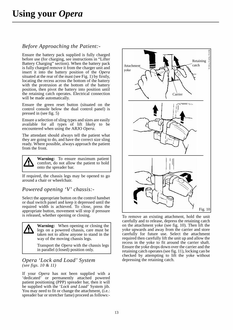
To remove an existing attachment, hold the unitcarefully and to release, depress the retaining catchon the attachment yoke (see fig. 10). Then lift theyoke upwards and away from the carrier and storecarefully for future use. Select the attachmentrequired then carefully lift the unit up and allow therecess in the yoke to fit around the carrier shaft.Ensure the yoke drops down over the carrier and theretaining catch operates (see fig. 11), locking can bechecked by attempting to lift the yoke withoutdepressing the retaining catch.
Warning: To ensure maximum patientcomfort, do not allow the patient to holdonto the spreader bar.
Warning: When opening or closing thelegs on a powered chassis, care must betaken not to allow anyone to stand in theway of the moving chassis legs.Transport the Opera with the chassis legsin parallel (closed) position only.
Fig. 10P1
391a
, P14
39a,
P14
39b
Attachment yoke
Carrier
Retaining catch
Using your Opera

14
Using the 4 point spreader barEnsure the spreader bar is securely connected to thejib before commencing with the lifting procedure.(‘Lock and Load’ system jib only).
To Lift from a ChairPlace the sling around the patient so that the base ofhis/her spine is covered, and the head support areais behind the head. Pull each leg piece under thethigh so that it emerges on the inside of the thigh.(See fig. 12).
Ensure the positioning handle on the spreader bar isfacing away from the patient, and that the wide partof the spreader bar is at, or just below shoulderlevel. (See fig. 13).
Ensure that the Opera is close enough to be able toattach the shoulder clips of the sling to the spreaderbar. To accomplish this you may have to put thepatients feet on, or over the chassis.Once the Opera is in position, attach the shoulderstrap attachment clips to the pegs on the spreaderbar. (See fig. 14).
Press down on the positioning handle of thespreader bar and attach the leg strap attachmentclips. (See fig. 15).
Fig. 11
P139
1bWarning: Care must be taken when theweight of the unit comes away from thejib.For larger attachments or if in any doubtabout being able to lift and hold theattachment securely use more than oneperson for the operation, or support theattachment on a bed or chair.
Fig. 12
P114
6a,b
Fig. 13
P139
2c
• Note: The chassis rear castors have brakes which can be foot operated when required (see fig.9). Do not apply the castor brakes at this stage, as the position of the patient will adjust to his/her own centre of gravity when lifted.
Fig. 14
P139
2d, P
1002
a,b,
c
Warning: Apply the castor brakes whenleaving the patient unattended or to keepthe Opera in position on a sloping surface.
Using your Opera

15
If necessary, lower the spreader bar using thehandset control, being careful not to lower it ontothe patient, although if this should happeninadvertently, there is a built in cut-out devicewhich will prevent any further downwardsmovement. Do not continue to press the handsetlowering button.
Raise the patient by operating the handset control,move the lifter away from the chair then carefullylift the positioning handle until the patient isreclined in the sling - the head support will nowcome into use. (See fig. 16). This is the mostcomfortable position for transportation, as itreduces pressure on the thighs. The angle of reclinecan be adjusted for increased comfort if the patientis restless.
Before transportation, turn the patient to face theattendant at approximately normal chair height.(See fig. 17). This gives confidence and dignity andalso improves the Opera mobility.
Remember to release the brakes, if they have beenapplied, before attempting to transport the patient.When lowering the patient back into a chair - orwhen transferring from bed to chair - push down onthe positioning handle to put the patient into a goodsitting position. This avoids further lifting effort.Take care not to push down too quickly, as this mayjerk the patient’s head forward.
Fig. 15P1
392e
• Note: If the handset button is released during lifting or lowering, powered motion will stop immediately.
Warning: IMPORTANT: Alwayscheck that the sling attachment clips arefully in position before and during thecommencement of the lifting cycle, and intension as the patient’s weight isgradually taken up.
Fig. 16
P139
3f
Fig. 17P1
393d
Warning: When lowering the lifterensure that the patient’s or attendant’slegs and feet are well clear of the movingmast.
Using your Opera
16
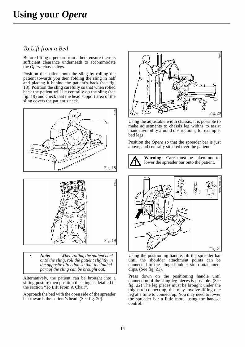
To Lift from a BedBefore lifting a person from a bed, ensure there issufficient clearance underneath to accommodatethe Opera chassis legs.Position the patient onto the sling by rolling thepatient towards you then folding the sling in halfand placing it behind the patient’s back (see fig.18). Position the sling carefully so that when rolledback the patient will lie centrally on the sling (seefig. 19) and check that the head support area of thesling covers the patient’s neck.
Alternatively, the patient can be brought into asitting posture then position the sling as detailed inthe section “To Lift From A Chair”.Approach the bed with the open side of the spreaderbar towards the patient’s head. (See fig. 20).
Using the adjustable width chassis, it is possible tomake adjustments to chassis leg widths to assistmanoeuvrability around obstructions, for example,bed legs.Position the Opera so that the spreader bar is justabove, and centrally situated over the patient.
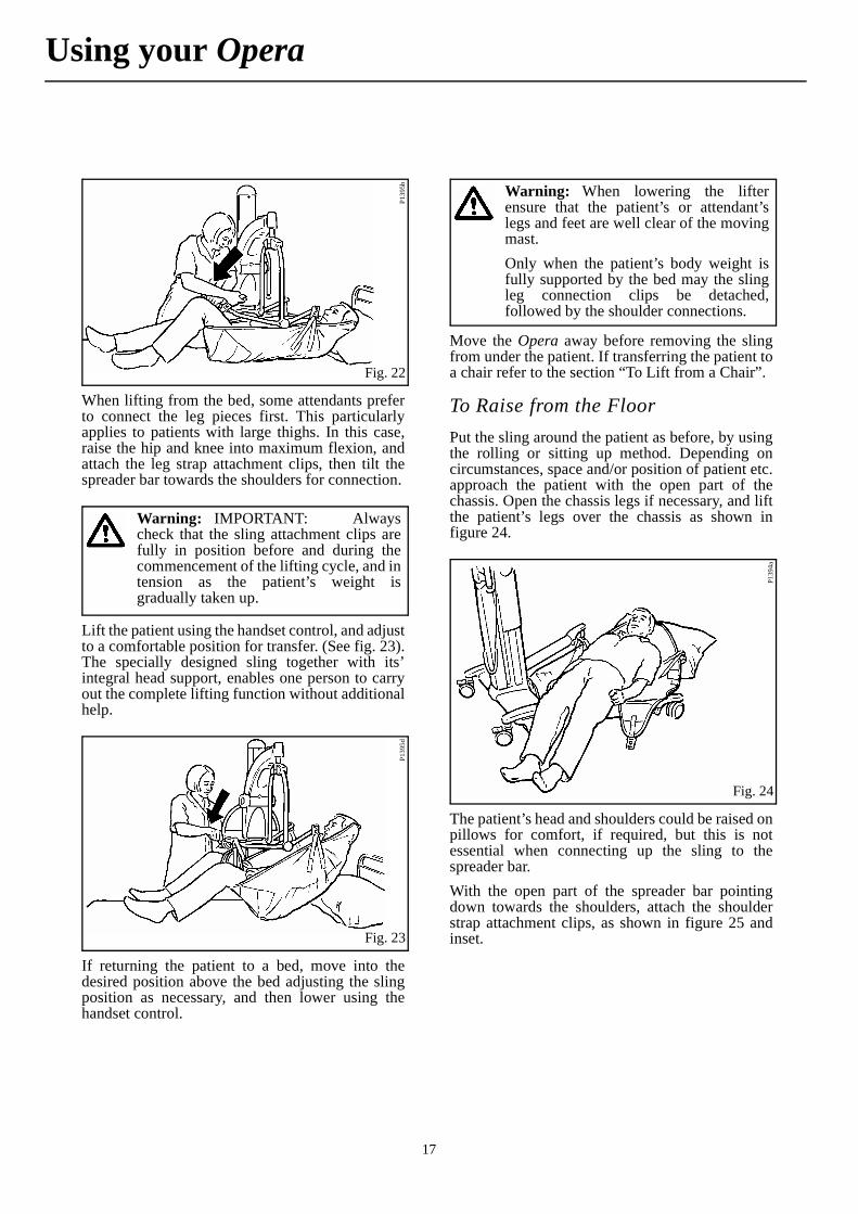
Using the positioning handle, tilt the spreader baruntil the shoulder attachment points can beconnected to the sling shoulder strap attachmentclips. (See fig. 21).Press down on the positioning handle untilconnection of the sling leg pieces is possible. (Seefig. 22) The leg pieces must be brought under thethighs to connect up, this may involve lifting oneleg at a time to connect up. You may need to lowerthe spreader bar a little more, using the handsetcontrol.
Fig. 18
P113
3b
Fig. 19
P102
2a
• Note: When rolling the patient back onto the sling, roll the patient slightly in the opposite direction so that the folded part of the sling can be brought out.
Fig. 20
P139
3e
Warning: Care must be taken not tolower the spreader bar onto the patient.
Fig. 21
P139
5a, P
1002
a,b
,c
Using your Opera
17
When lifting from the bed, some attendants preferto connect the leg pieces first. This particularlyapplies to patients with large thighs. In this case,raise the hip and knee into maximum flexion, andattach the leg strap attachment clips, then tilt thespreader bar towards the shoulders for connection.
Lift the patient using the handset control, and adjustto a comfortable position for transfer. (See fig. 23).The specially designed sling together with its’integral head support, enables one person to carryout the complete lifting function without additionalhelp.
If returning the patient to a bed, move into thedesired position above the bed adjusting the slingposition as necessary, and then lower using thehandset control.
Move the Opera away before removing the slingfrom under the patient. If transferring the patient toa chair refer to the section “To Lift from a Chair”.
To Raise from the FloorPut the sling around the patient as before, by usingthe rolling or sitting up method. Depending oncircumstances, space and/or position of patient etc.approach the patient with the open part of thechassis. Open the chassis legs if necessary, and liftthe patient’s legs over the chassis as shown infigure 24.
The patient’s head and shoulders could be raised onpillows for comfort, if required, but this is notessential when connecting up the sling to thespreader bar.With the open part of the spreader bar pointingdown towards the shoulders, attach the shoulderstrap attachment clips, as shown in figure 25 andinset.
Fig. 22
P139
5b
Warning: IMPORTANT: Alwayscheck that the sling attachment clips arefully in position before and during thecommencement of the lifting cycle, and intension as the patient’s weight isgradually taken up.
Fig. 23
P139
5d
Warning: When lowering the lifterensure that the patient’s or attendant’slegs and feet are well clear of the movingmast.Only when the patient’s body weight isfully supported by the bed may the slingleg connection clips be detached,followed by the shoulder connections.
Fig. 24
P139
4a
Using your Opera

18
Once connected, raise the hip and knee intomaximum flexion, and push down on thepositioning handle in order to connect the leg strapattachment clips as shown in figure 26. This willhave the effect of raising the patient’s head andshoulders slightly.
When lifting from the floor, some attendants preferto connect the leg pieces first. This in particularapplies to the very large patient with large thighs. Inthis case, raise the hip and knee into maximumflexion, and attach the leg straps first, then tilt thespreader bar towards the shoulders to enable theshoulder straps to be connected.When all the straps have been properly connected,raise the patient from the floor in a semi-recumbentposition. Supporting the head can be comfortableand reassuring for the patient. Once raised from thefloor, ensure the patient’s legs are clear of the
chassis before continuing to lift. (See fig. 27). Theleg sections of the sling will tend to be fairly highin the crotch, so straighten them out for addedcomfort. The patient may be positioned in a chair,or placed onto a bed. If the patient is prone toextensor spasm, he/she may be lifted by the Opera,but special attention should be paid to supportingthe legs during the early part of the lift.
When lifting patient’s with leg amputations, use thedouble amputee sling (available as an accessoryfrom ARJO Ltd). This sling is specially designed toaccommodate the differing patient centre ofgravity.
At the ToiletFor toileting a patient, use the toilet sling with headrest. The toilet sling is fitted in a similar manner tothe standard four point sling, except, the sling is nottaken to the base of the patient’s spine, but fittedwith the top of the head support area of the slinglevel with the top of the patients head as a guide topositioning. (See fig 28)
Fig. 25P1
394b
, P10
02 a
,b,c
Fig. 26
P139
4c
Warning: IMPORTANT: Alwayscheck that the sling attachment clips arefully in position before and during thecommencement of the lifting cycle, and intension as the patient’s weight isgradually taken up.
Fig. 27
P139
4d
Warning: When lowering the lifterensure that the patient’s or attendant’slegs and feet are well clear of the movingmast.Transportation of a patient should alwaysbe done with the chassis legs parallel(closed) manoeuvrability will be easier,especially through doorways, with thechassis legs closed. The patient should bepositioned facing the attendant. (See fig.17). Apply the chassis brakes if leavingthe patient unattended.
Using your Opera

19
The ARJO toilet sling has been specially designedto help support patients whilst toiletting.
To provide the best possible access when toilettingthe sling has a wide commode opening and becauseof this it is essential that:-(a) The correct size sling is chosen, relative to the
weight and height of patient and (b) Both of the patient’s arms are positioned
outside the sling, over the padded areas but under the “head section” support straps’ (See fig. 28) this will help prevent the patient from sliding through the sling.
When used in accordance with these instructions
the toiletting sling provides a very effective methodof toiletting dependent patients.Once the patient has been lifted and transported tothe toilet, position the lifter so that the patient ispositioned above the toilet seat.
Apply the chassis brakes.Unbutton and / or remove the patients garmentslower the patient to a comfortable sitting position.
Powered Patient Positioning Spreader Bar (if fitted)If your lifter has been supplied fitted with aPowered Patient Positioning (P.P.P.) spreader bar,the use of this type of spreader bar including slingpositioning with patient, sling connection to thespreader bar, and patient handling, is the same asthe non-powered 4 point spreader bar describedpreviously in these instructions.
The fundamental difference being, the “P.P.P.”spreader bar has the added advantage of enablingthe patient positioning manoeuvre to be performedwith minimal physical effort by the attendant.
Fig. 28
P113
0a
“Head Section”support strap buckles
Warning: It is essential to familiariseyourself with the correct method of usebefore any attempt is made to lift apatient.Always ensure that the patient hassufficient trunk and head self-control tobe safely lifted in the toilet sling. If in anydoubt use the standard type sling.
• Note: It is advisable to release the “head section” support strap buckles prior to fitting the sling, once the sling is around the patient, reconnect the support strap buckles ensuring the patient’s arms are positioned over the sling.
Warning: Always ensure that thepatient, when suspended, is in an uprightsitting position, as shown in figure 28.
Warning: When lowering the lifterensure that the patient’s or attendant’slegs and feet are well clear of the movingmast.
Warning: Always use the toilet slingwith caution, encourage the patient tohold tightly to the sling to avoid slidingout. Do not use the toilet sling for liftingand transportation apart from toilet visits.
Fig. 29
P139
7aJib
Motor cover
Gearbox covers
Support frame
Sling attachment lugs
Isolator/cut-off switch
Positioning control handle
Spreader bar
Using your Opera
20
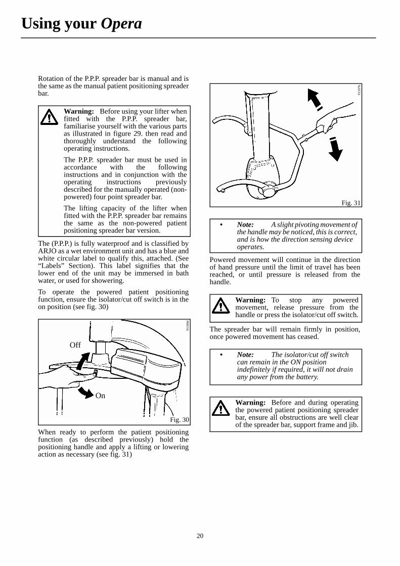
Rotation of the P.P.P. spreader bar is manual and isthe same as the manual patient positioning spreaderbar.
The (P.P.P.) is fully waterproof and is classified byARJO as a wet environment unit and has a blue andwhite circular label to qualify this, attached. (See“Labels” Section). This label signifies that thelower end of the unit may be immersed in bathwater, or used for showering.To operate the powered patient positioningfunction, ensure the isolator/cut off switch is in theon position (see fig. 30)
When ready to perform the patient positioningfunction (as described previously) hold thepositioning handle and apply a lifting or loweringaction as necessary (see fig. 31)
Powered movement will continue in the directionof hand pressure until the limit of travel has beenreached, or until pressure is released from thehandle.
The spreader bar will remain firmly in position,once powered movement has ceased.
Warning: Before using your lifter whenfitted with the P.P.P. spreader bar,familiarise yourself with the various partsas illustrated in figure 29. then read andthoroughly understand the followingoperating instructions.The P.P.P. spreader bar must be used inaccordance with the followinginstructions and in conjunction with theoperating instructions previouslydescribed for the manually operated (non-powered) four point spreader bar.The lifting capacity of the lifter whenfitted with the P.P.P. spreader bar remainsthe same as the non-powered patientpositioning spreader bar version.
Fig. 30
P138
9d
Off
On
Fig. 31
P139
7b
• Note: A slight pivoting movement of the handle may be noticed, this is correct, and is how the direction sensing device operates.
Warning: To stop any poweredmovement, release pressure from thehandle or press the isolator/cut off switch.
• Note: The isolator/cut off switch can remain in the ON position indefinitely if required, it will not drain any power from the battery.
Warning: Before and during operatingthe powered patient positioning spreaderbar, ensure all obstructions are well clearof the spreader bar, support frame and jib.
Using your Opera

21
Patient positioning function cut out fuseIf an obstruction is encountered accidentally duringupward or downward movement then an automaticcut out fuse will operate to protect the system. Thefuse will reset quickly once powered movement hasceased, the obstruction or lifter should be moved toavoid this re-occurring. If the patient positioningfunction cut out fuse operates again, withdraw thelifter from use and contact ARJO Servicedepartment.
Care Of Your Powered Patient Positioning Spreader BarFor general care refer to the “Care Section”. Referin particularly to paragraphs relating to cleaning,plastic parts, labels, etc.
Using the 2 point spreader bar
The slings to be used with the 2 point spreader barare the ARJO loop slings (see fig. 2). They areavailable in four sizes (small, medium, large andextra large) all colour coded. A range of morespecialised slings are available please contactARJO or their authorised distributors for details.The loop sling is available with or without headsupport. A bathing mesh sling is also available in allthe four sizes with or without head support.
To Lift from a ChairMethod 1 - Easing the patient forward, if necessary,slide the sling down the patient’s back until seam“C” (see fig. 33) reaches the base of the spine. Takeattachment points “B” and loop the tails of the slingunderneath the patient’s thighs, ensuring the slingpieces are not twisted underneath the patient. Hookthe loops onto the “opposite side” outer hooks onthe spreader bar. (See fig. 34).
Warning: The motor and gearboxcovers house moving parts, care must betaken not to damage these covers. Shouldthe covers become damaged, withdrawthe lifter from use and arrangereplacement of the cover/s before re-usingthe lifter.
Warning: Apart from cleaning no usermaintenance is required, but somecomponents may need to be serviced orreplaced periodically. This should becarried out by an ARJO qualified serviceengineer. For more information contactARJO or their approved distributor. Seealso ‘Servicing Advice’ in the ‘Care’section.
Fig. 32
P139
4f
Warning: Before attaching the slingensure the spreader bar is rotated intoposition so the eventual lift will resemblefigure 32.
Fig. 33
P139
5e, m
P113
8e/2
A
BC
A
B
Using your Opera
22
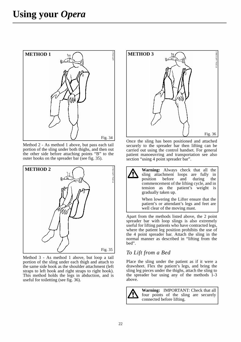
Method 2 - As method 1 above, but pass each tailportion of the sling under both thighs, and then outthe other side before attaching points “B” to theouter hooks on the spreader bar (see fig. 35).
Method 3 - As method 1 above, but loop a tailportion of the sling under each thigh and attach tothe same side hook as the shoulder attachment (leftstraps to left hook and right straps to right hook).This method holds the legs in abduction, and isuseful for toiletting (see fig. 36).
Once the sling has been positioned and attachedsecurely to the spreader bar then lifting can becarried out using the control handset. For generalpatient manoeuvring and transportation see alsosection “using 4 point spreader bar”.
Apart from the methods listed above, the 2 pointspreader bar with loop slings is also extremelyuseful for lifting patients who have contracted legs,where the patient leg position prohibits the use ofthe 4 point spreader bar. Attach the sling in thenormal manner as described in “lifting from thebed”.
To Lift from a BedPlace the sling under the patient as if it were adrawsheet. Flex the patient’s legs, and bring thesling leg pieces under the thighs, attach the sling tothe spreader bar using any of the methods 1-3above.
Fig. 34
mP1
183a
/2METHOD 1
Fig. 35
P139
5e, m
P113
8c/2METHOD 2
Fig. 36
P139
5e, m
P113
8b/2METHOD 3
Warning: Always check that all thesling attachment loops are fully inposition before and during thecommencement of the lifting cycle, and intension as the patient’s weight isgradually taken up.When lowering the Lifter ensure that thepatient’s or attendant’s legs and feet arewell clear of the moving mast.
Warning: IMPORTANT: Check that allfour points of the sling are securelyconnected before lifting.
Using your Opera
23
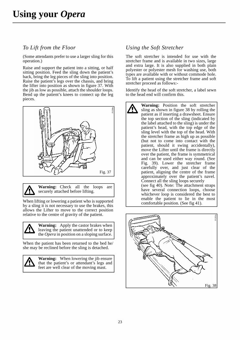
To Lift from the Floor(Some attendants prefer to use a larger sling for thisoperation.)Raise and support the patient into a sitting, or halfsitting position. Feed the sling down the patient’sback, bring the leg pieces of the sling into position.Raise the patient’s legs over the chassis, and bringthe lifter into position as shown in figure 37. Withthe jib as low as possible, attach the shoulder loops.Bend up the patient’s knees to connect up the legpieces.
When lifting or lowering a patient who is supportedby a sling it is not necessary to use the brakes, thisallows the Lifter to move to the correct positionrelative to the centre of gravity of the patient.
When the patient has been returned to the bed he/she may be reclined before the sling is detached.
Using the Soft StretcherThe soft stretcher is intended for use with thestretcher frame and is available in two sizes, largeand extra large. It is also supplied in both plainpolyester or polyester mesh for washing use, bothtypes are available with or without commode hole.To lift a patient using the stretcher frame and softstretcher proceed as follows:-Identify the head of the soft stretcher, a label sewnto the head end will confirm this.
Fig. 37
P139
4e
Warning: Check all the loops aresecurely attached before lifting.
Warning: Apply the castor brakes whenleaving the patient unattended or to keepthe Opera in position on a sloping surface.
Warning: When lowering the jib ensurethat the patient’s or attendant’s legs andfeet are well clear of the moving mast.
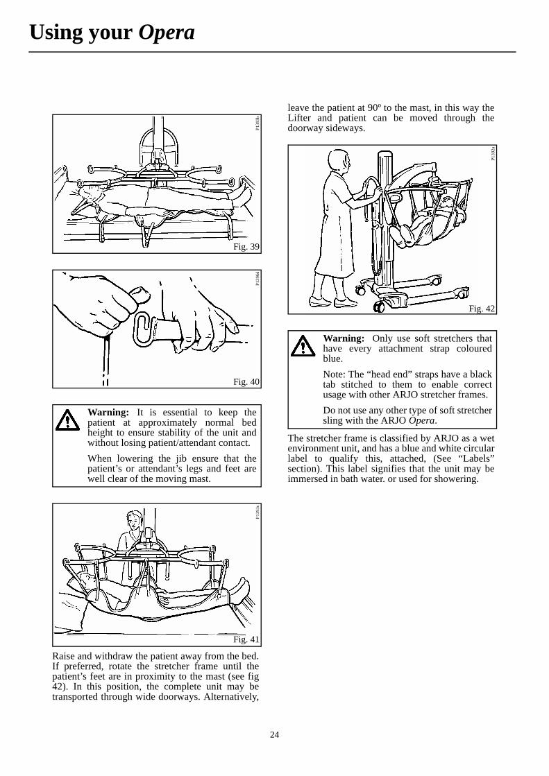
Warning: Position the soft stretchersling as shown in figure 38 by rolling thepatient as if inserting a drawsheet. Ensurethe top section of the sling (indicated bythe label attached to the sling) is under thepatient’s head, with the top edge of thesling level with the top of the head. Withthe stretcher frame as high up as possible(but not to come into contact with thepatient, should it swing accidentally),move the Lifter until the frame is directlyover the patient, the frame is symmetricaland can be used either way round. (SeeFig. 39). Lower the stretcher framecarefully over, and just clear of thepatient, aligning the centre of the frameapproximately over the patient’s navel.Connect all the sling loops securely (see fig 40). Note: The attachment strapshave several connection loops, choosewhichever loop is considered the best toenable the patient to lie in the mostcomfortable position. (See fig 41).
Fig. 38
P139
3a
Using your Opera
24
Raise and withdraw the patient away from the bed.If preferred, rotate the stretcher frame until thepatient’s feet are in proximity to the mast (see fig42). In this position, the complete unit may betransported through wide doorways. Alternatively,
leave the patient at 90º to the mast, in this way theLifter and patient can be moved through thedoorway sideways.
The stretcher frame is classified by ARJO as a wetenvironment unit, and has a blue and white circularlabel to qualify this, attached, (See “Labels”section). This label signifies that the unit may beimmersed in bath water. or used for showering.
Fig. 39P1
393b
Fig. 40
P139
6d
Warning: It is essential to keep thepatient at approximately normal bedheight to ensure stability of the unit andwithout losing patient/attendant contact.When lowering the jib ensure that thepatient’s or attendant’s legs and feet arewell clear of the moving mast.
Fig. 41
P139
3c
Fig. 42
P139
2a
Warning: Only use soft stretchers thathave every attachment strap colouredblue.Note: The “head end” straps have a blacktab stitched to them to enable correctusage with other ARJO stretcher frames.Do not use any other type of soft stretchersling with the ARJO Opera.
Using your Opera

25
Using the Strap Stretcher
Firstly attach the 12 cross straps to one of the sidesections (see fig.43), by pushing each strap througha locking clamp and locking by pressing the claspfully down, initially leave approximately 200mm (8inches) of strap outside the clamp (see inset tofig.43).
Ensure the patient to be lifted is free of bed covers,place one end tube above the patient’s head and onebelow the feet. Next, place the “unstrapped” side
section to the side of the patient (clampsuppermost) (see fig. 44) and push each end tubethrough the corresponding holes in the side sections(matching the coloured arrowed labels).Hold the “strapped” side section with the longerlength of the straps hanging towards the patient andplace it on the bed beside the patient, with thelonger length of the straps folded under the sidesection (see fig. 45). Connect the end tubes asbefore (matching the coloured arrowed labels).
Head End(Straps closer together)
Side Section (Right hand)
End tube
Approx.200mm (8”)
(Loose end of strap)
Strap Locking Clamp
Cross Straps
Clasp
End tubeSide Section (Left hand)
Loose end of strap
Patients Weight
Suspension straps
Suspensionpoint label
Side Section Orientation Label
Strap Guide
Fig. 43
mP1
278:
P10
05a2
, 100
5b, P
1167
a, P
1169
, P12
65
Warning: Red and green indicatorarrow labels indicate the correct positionsfor frame assembly, noting that the threeclosely positioned strap clamps go to thehead end of the patient, (a label on eachside section also indicates this).
Using your Opera

26
Slide any strap that can be easily done so, under thepatient, perhaps by carefully lifting the patient’shead and legs. For straps under the weight of thepatient use the strap guide as follows.
Thread the long section of the strap that is to gounder the patient through the strap guide as showninset in figure 46. Then gently push the strap andguide under the patient (see fig. 46) until the strapcan be pulled clear and connected through theopposite strap clamp. Slide the guide back out fromunder the patient keeping the guide under thepositioned strap.
Fig. 44
P100
6b
Fig. 45
• Note: If desired the straps may be passed under the pillow thereby leaving it under the patient’s head for added comfort (see fig 47).
Fig. 46
mP1
279:
P10
06d2
, P11
67b
End of cross strap to bepushed under patient
Strap guide
Loose end of strap
Warning: With obese patientsespecially, or under buttocks, care mustbe taken initially, not to trap any skin, asthe strap guide is fed under the patient.Continue until all the straps are under thepatient and through the clamps, ensureeach strap is pulled tight and locked intoposition by pressing each clasp fullydown (see fig. 43 and 48).All cross straps must enter directly intothe clamps, and must not be passedaround the side section (see fig. 43) Check that both end tubes are fullylocated into each side section (with thecorrect matching arrow labels).
Warning: If not already attached, fix thefour suspension straps in the positionsindicated by labels on the side sections(see fig 49)
Using your Opera
27
Once connected, operate the Lifter to lift the patientclear of the bed, then either, rotate the stretcherframe until the patient’s feet are in proximity to themast. In this position, the complete unit may betransported through wide doorways. Alternatively,leave the patient at 90º to the mast, in this way theLifter and patient can be moved through thedoorway sideways.
P114
0c
Fig. 47
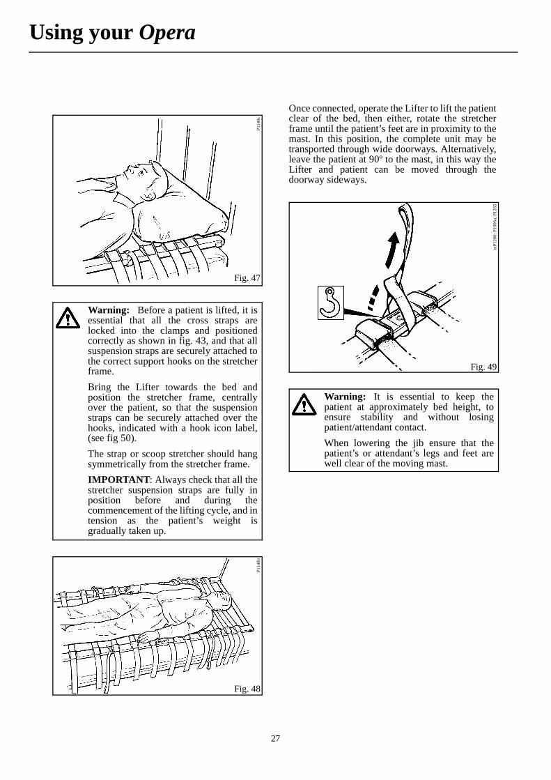
Warning: Before a patient is lifted, it isessential that all the cross straps arelocked into the clamps and positionedcorrectly as shown in fig. 43, and that allsuspension straps are securely attached tothe correct support hooks on the stretcherframe.Bring the Lifter towards the bed andposition the stretcher frame, centrallyover the patient, so that the suspensionstraps can be securely attached over thehooks, indicated with a hook icon label,(see fig 50).The strap or scoop stretcher should hangsymmetrically from the stretcher frame.IMPORTANT: Always check that all thestretcher suspension straps are fully inposition before and during thecommencement of the lifting cycle, and intension as the patient’s weight isgradually taken up.
Fig. 48
P114
0b
Fig. 49
mP1
280:
P10
06a,
P12
65
Warning: It is essential to keep thepatient at approximately bed height, toensure stability and without losingpatient/attendant contact.When lowering the jib ensure that thepatient’s or attendant’s legs and feet arewell clear of the moving mast.
Using your Opera

28
When the patient is returned and lowered on to thebed, the strap stretcher may be removed, oncedisconnected from the stretcher frame, byslackening all the clamps on one side section andgently pulling each strap through under the patient.Disconnect and remove the frame, store carefullyfor future use.
Patient Scale (if fitted)See seperate supplementary operating instructions.
Fig. 50
mP1
389a
, P13
96d,
P12
65Strap and scoop stretcher connection hook positions
label - hook positions for strap and scoop stretcher attachment straps
• Note: Individual patient support straps can be slackened and removed if access is required to any part of the patient needing attention.
Warning: Do not remove too manystraps at one time to ensure the patient issecurely supported.
Using your Opera
29
The Opera incorporates a battery dischargeindicator, situated on the rear side of the controlsconsole (see Fig. 1). The display shows ten levels ofbattery state ranging from fully charged on the rightto very low on the left (green, through amber to red)
For more details of caring for your lifter batteryrefer to the ‘Battery Care’ literature, ARJO Part No.KDX01660.GB.
It is recommended that the battery is removed fromthe lifter and recharged when the display reachesthe yellow range, but lifting is possible until thedisplay shows the red flashing light, at this point,the battery must be recharged as soon as possible.Recharging the battery pack before it reaches a lowstate of battery charge or certainly totallydischarged will prolong its life.Your lifter is fitted with an audible warning devicethis will sound when the battery discharge indicatorreaches the red light range. The audible warningwill sound for approximately thirty seconds andwill start when a function button is pressed.Pressing the emergency stop button willtemporarily silence this function, removing andreplacing the battery with one fully charged willsilence the alarm until low battery condition re-activates it.
Danger: The charger is for indoor useonly.Only use the charger unit in a dryenvironment, do not use it in thebathroom.Do not expose the charger unit or batterypack to rain or spray and do not immersein water.Only use the ARJO battery that issupplied to be used with the OperaThe battery charger is for use only withARJO supplied batteries that are to beused with the OperaThe battery charger is for use with sealedlead acid batteries only.Under no circumstances should thecharger be used to attempt to rechargenon-rechargable batteries.Do not attempt to open or tamper with thecharger unit in any way, for any repair thecharger must be sent to the manufacturerThe mains electricity socket must beeasily accessible. should a faultycondition occur switch off and remove theconnection plug from the socket.Only use ARJO components that havebeen specifically designed for the purposewhen charging batteries.
Warning: To avoid overheating, thecharger must not be covered whilst in use.No smoking or naked flames in batteryvicinity.Do not expose the charger unit to dust.Do NOT charge batteries in a sealedcontainer.Do NOT place batteries near, or disposeof, in a fire.Do NOT short circuit a battery.
Warning: Do NOT store batteries attemperatures in excess of 60°C (140°F).Do NOT crush, puncture, open, dismantleor otherwise mechanically interfere withbatteries.Should the battery casing becomecracked, and electrolyte come into contactwith skin or clothing, wash immediatelywith water.If the electrolyte contacts the eyes, washimmediately with copious amounts ofwater, and seek medical attention.When disposing of batteries, contact theappropriate local authority for advice.The abbreviation “Pb” shown adjacent tothe recycling and trash bin symbols on thebattery pack label is the element symbolfor lead, and indicates that the batterycontains lead and therefore should not bedisposed of in the normal manner butmust be recycled.
• Note: The battery discharge indicator has an energy saving function which automatically switches off the display if a function button has not been operated for at least 30 seconds. The moment a button is pressed to operate any function the display will re-start.
Lifter Battery Charging
30
To ensure the Opera is always ready for use, it isrecommended that a freshly charged battery pack isalways available. This is achieved by havingadditional battery packs available and keeping oneon charge while the other is in use.It may be considered good protocol to have afreshly charged battery ready for the start of everywork shift.
Place the battery pack on charge as follows:
When the LED on the battery discharge indicatordisplays amber, complete your lift cycle then takethe lifter to a convenient situation and remove thebattery pack by holding the grip position of thebattery and pressing the release catch situatedabove, pivot the battery away and lift clear. Takethe battery to the battery charger unit and ensure thebattery is positioned securely then insert the batteryconnector from the charger into the correspondingconnector in the back of the battery (see fig. 55),switch on mains power. An orange light will bedisplayed on the charger unit when the battery istotally discharged. This will change to a yellowlight as the battery approaches full charge capacity,finally changing to a green light when the battery isfully charged.A discharged battery should be left approximately8 hours to totally recharge (See also ARJO BatteryCare document).
When the battery pack is fully charged, disconnectthe mains power, remove the battery pack from thecharger, and insert it back into the Opera batteryposition.Ensure the green reset button (situated on the rearof the mast) is pressed in (see fig. 1).The Opera is now ready for use.
• Note: Whichever level the indicator has reached, once a fully charged battery is re-inserted into the lifter, the display will return to the green fully charged position, but if a partially charged battery is re-inserted, the level at which the indicator had reached will remain, even though the recently inserted battery may be in a better state of charge than indicated. To achieve a true indication of battery state a fully charged battery must be inserted into the lifter to reset the indicator.
Caution: Ensure the mains power tothe charger unit is switched off beforeconnecting the battery.
Warning: Always ensure the cableconnection plugs that fit into the chargerand into the battery are fully insertedbefore switching on mains electricity.
Fig. 51
P139
1d
• Note: The cable that connects the main electricity supply to the charger is supplied as a detachable item. If using the battery charger for the first time or if the cable has been unplugged from the charger, connect the cable fully into the charger before connecting to the mains electrical.
Warning: Hold the pack firmly toensure it does not drop and becomedamaged, or cause personal injury.
• Note: The battery pack may be left connected to the charger unit when it is fully charged without being damaged by overcharging, this will also ensure the battery is kept fully charged.
Caution: Always disconnect the mainssupply before disconnecting the batterycharger unit.
Lifter Battery Charging
31
How often the following actions are taken dependson how often the equipment is used.Unless otherwise stated, before each and every usefollow the cleaning, care and inspection proceduresdescribed in this section.
Sling care and cleaning:-
Lifter care and cleaning:-
Warning: The slings should be checkedbefore and after use with each patient andif necessary washed according toinstructions on the sling, This is especiallyimportant when using the same equipmentfor another patient, to minimise the risk ofcross infection. Also refer to slinginstruction sheet MAX.01510.INT.With regard to laundering, slings shouldnot be classified as linen, but as anaccessory to a patient transfer lifter andtherefore classified as a medical device.Slings should be cleaned and disinfectedonly in strict accordance with themanufacturers instructions.Mechanical pressure should be avoidedduring the washing and drying proceduree.g. rolling or pressing, as these candamage parts vital to the safe andcomfortable operation of the sling.The strap stretcher cross straps andsuspension straps should be checked andif necessary washed. Washing and dryingtemperatures must not exceed 80°C(176°F). Wash using normal detergents,do not iron. Also refer to Sling Instructionsheet MAX.01510.INT.It is essential that the sling attachmentcords, the slings, their straps andattachment clips are carefully inspectedbefore each and every use. If the slings,cords or straps are frayed, or the clipsdamaged, the sling or attachment cordshould be withdrawn from useimmediately and replaced.
Warning: It is recommended thatpatient lifters, equipment, accessories areregularly cleaned and/or disinfectedbetween each patient use if necessary, ordaily as a minimum. If the lifter and/orequipment needs cleaning, or is suspectedof being contaminated, follow thecleaning and/or disinfection proceduresrecommended below, before re-using theequipment.For cleaning your lifter, equipment andaccessories wipe down with a damp clothusing warm water to which a disinfectant/cleaner has been added e.g. “ARJOCLEAN” - disinfectant/cleaner orequivalent
• Note: “ARJO CLEAN” - disinfectant cleaner is available from ARJO Ltd. or their approved distributors.
Caution: Do not over wet areas of theproduct which could cause problems withelectrical components or internalcorrosion.If a hot air dryer is used to dry the lifter,the temperature must not exceed 80°C(176°F)Do not use petroleum based solvents orsimilar, since this may damage plasticparts.
Warning: For disinfection ofcontaminated lifters, equipment andaccessories, use the preferred method ofwiping the product completely with “hardsurface disinfectant wipes” that aresupplied impregnated with a 70% v/vsolution of Isopropyl Alcohol.
• Note: A rubbing action will be necessary when using the wipes to promote effective disinfection of the surfaces.
Care of your Opera

32
The following checks should be carried out daily.Ensure that the battery pack is always in a goodstate of charge.
Periodic TestingTo be carried out at weekly intervals.Periodic testing of the operational functions isadvisable from time to time to ensure everythingoperates satisfactorily. Test for full and efficient movement of the lift /lower mechanism:- Raise and lower the jib usingthe control handset, test also with dual switchpanel.Automatic Stop Function:- With the jib wellabove its lowest position and the lifter positionedover an empty bed, use the handset control to lowerthe jib onto the bed. As the jib lowering isrestricted, the motor will stop, release the controlhandset lower button after a second or two. Raisethe jib using the control handset, then repeat the testusing the dual switch panel, this check is for thecorrect functioning of the automatic stop.
Emergency Stop:- Test the emergency stopfacility by operating the control handset to lift orlower the jib, and whilst operating, press in theemergency stop button (see fig. 5). Poweredmovement should stop immediately.Reset to normal function by pressing the green resetbutton (see fig. 5). Repeat this test using the dualswitch panel, reset to normal function. Repeat forchassis legs opening / closing function, and resetthe button.System Failure Lower Override:- Test thisfunction simply by ensuring the jib is well above itslowest position then operate the system failurelower override switch (see fig. 5). The jib willlower without the need to operate the controlhandset or dual control panel. The lower overridefacility will still operate even with the handsetcontrol cable unplugged.Adjustable Width Chassis Function:- Open andclose the chassis legs using the control handset anddual switch panel, to check for full and efficientmovement.General lifter Condition:- A general visualinspection of all external parts should be carriedout, and all functions should be tested for correctoperation, to ensure that no adverse damage hasoccurred during use.
Servicing Advice
Warning: IMPORTANT: Cleaningand disinfection products must be used inaccordance with the manufacturersinstructions and suitable eye, hand andclothing protection must be worn at alltimes when handling disinfectants.
• Note: 70% v/v Isopropyl Alcohol wipes have been proved to be effective against MRSA and several other micro-organisms under light soiling conditions.
Warning: Ensure that the castors arefirmly secured to the chassis.Carefully inspect all parts, in particularwhere there is personal contact with thepatient’s body, ensure that no cracks orsharp edges have developed which couldinjure the patient’s skin or becomeunhygienic.Check that all external fittings are secureand that all screws and nuts are tight.Ensure that all instruction labels arefirmly attached and in good readablecondition.
Warning: If in any doubt about thecorrect functioning of the Opera,withdraw it from use and contact ARJOService Department.
Warning: ARJO recommend that theOpera is maintained at regular intervals,see ARJO Opera Preventive maintenanceschedule (ARJO Literature Part No.PMS011/Opera)With regular use the following items aresubject to wear:- slings, batteries, straps,castors. These items must be regularlychecked as described previously, andreplaced as necessary.
Care of your Opera

33
Parts list and circuit diagrams are available from ARJO or their approved distributors on request.
Special tools are required for certain componentreplacement
Warning: UK LIFTERS ONLY:Important legislation came into force on5th December 1998, which has an impacton the schedule of service for your patientlifter(s), variable height baths and otherraising and lowering equipment. TheLifting Operations and Lifting EquipmentRegulations (LOLER) 1998 and TheProvision and Use of Work EquipmentRegulations (PUWER 98) must besatisfied by the duty holder. A scheme ofsix monthly thorough examinations hasbeen devised to comply with the law anddetails can be obtained from ARJOService UK
Warning: Spare parts, if required areavailable from ARJO or their approveddistributors.
Warning: The simplest, safest and mosteffective way to maintain your product ingood working order, is to have itmethodically and professionally servicedby an ARJO approved engineer usingARJO approved spare parts.For information on service andmaintenance contracts, please contactyour local ARJO distributor.
Care of your Opera
34
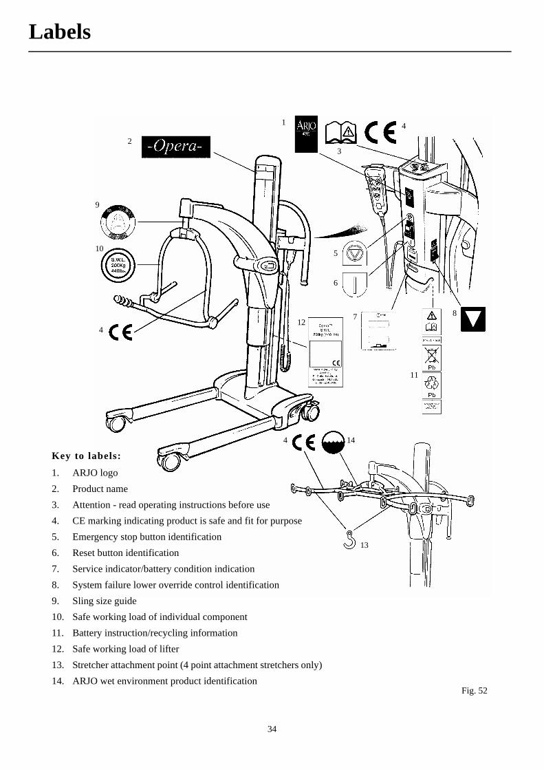
Fig. 52
Key to labels:
1. ARJO logo2. Product name3. Attention - read operating instructions before use4. CE marking indicating product is safe and fit for purpose5. Emergency stop button identification6. Reset button identification7. Service indicator/battery condition indication8. System failure lower override control identification9. Sling size guide10. Safe working load of individual component11. Battery instruction/recycling information12. Safe working load of lifter13. Stretcher attachment point (4 point attachment stretchers only)14. ARJO wet environment product identification
1
23
4
5
6
7 8
9
10
11
12
13
144
4
Labels

35
Component Weightskg lbs
Opera (mast with ‘Lock and Load’ jib) - less battery ................. ..........36.9 (81.3)Opera (mast with ‘Lock and Load’ scale jib) - less battery ........ ..........40.1 (88.4)Opera (mast with P.P.P. jib with 4 point spreader bar) - less battery ......46.4 (102.3)Opera (mast with P.P.P. scale jib with 4 point spreader bar) - less battery ........................................................... ..........49.6 (109.3)‘V’ opening chassis ...................................................................... ..........21.1 (46.5)4 point spreader bar ‘Lock and Load’ system .............................. ..........6.0 (13.2)2 point spreader bar ‘Lock and Load’ system .............................. ..........2.1 (4.6)Stretcher frame ............................................................................. ..........7.0 (15.4)Scoop stretcher ............................................................................. ..........9.7 (21.3)Strap stretcher............................................................................... ..........13.6 (29.9)Battery pack.................................................................................. ..........4.9 (10.8)
ElectricalBattery type and part number ...................................................... (Rechargable - lead acid) KPA0100Battery capacity ........................................................................... 5AhBattery charger part number ........................................................ KPA0101**
(Note: ** indicates relevant country code)Handset - Protection class ........................................................... IP67Lifter nominal voltage ................................................................. 24V DCMedical Equipment:- type protection against electrical shock in accordance with IEC 601-1)ARJO patient handling products meet the requirements of Electromagnetic Compatibility (EMC) as stated inclause 12.5 of the Medical Devices Directive 93/42/EEC
Duty cycle Max volts Max ampsMast Lift Actuator ....................................................................... 15% (9 min/hr) 24 8‘V’ Chassis Actuator ................................................................... 10% (6 min/hr) 24 4.5
ScalePower supply ................................................................................ 6 Volt DC (4 x AA Batteries)Battery life.................................................................................... 120hrsAccuracy....................................................................................... 2-120kg (4-265lbs) ± 100g (0.2lb)Accuracy....................................................................................... 4-200kg (10-440lbs) ± 200g (0.5lb)Protection class............................................................................. IP 53
EnvironmentAir humidity/storage .................................................................... 80% @ 20°C (68°f)Usage temperature range (ambient) .............................................. +5°C (41°F) to +35°C (95°F)Optimum usage temperature (ambient)......................................... +20°C (68°F) to +25°C (77°F)Storage and transportation temperature (ambient) .................................. -10ºC (14ºF) to +45ºC (113ºF)
Technical Specification
36
The Opera should not be loaded with a weight in excess of the lowest rated attachment fitted (see table below for lifter and attachments maximum lifting capacities).MAXIMUM CAPACITIES OF OPERAAll slings - 200kg (440lbs)Lifter + ‘Lock and Load’ jib + 4 point spreader bar - 200kg (440lbs)Lifter + ‘Lock and Load’ jib + 2 point spreader bar - 200kg (440lbs)Lifter + ‘Lock and Load’ jib + stretcher frame + strap stretcher - 160kg (352lbs)Lifter + ‘Lock and Load’ jib + stretcher frame + soft stretcher - 160kg (352lbs)Lifter + ‘Lock and Load’ jib + stretcher frame + scoop stretcher - 160kg (352lbs)Lifter + Dedicated jib with 4 point P.P.P. spreader bar - 200kg (440lbs)Lifter + 200mm Extended ‘Lock and Load’ jib + 4 point spreader bar - 130kg (286lbs)Lifter + 200mm Extended dedicated jib with 4 point P.P.P. spreader bar - 130kg (286lbs)The capacities given are correct for the lifter configurations listed, but some accessories/additional/optional subassemblies may reduce the maximum capacity. Always refer to the maximum weight limit printed on the labelfixed to the lowest rated fitted attachment.
Technical Specification
37
Technical Specification

38
Notes

39
Notes

Prin
ted
in G
reat
Brit
ain.
FM 21964ISO 9001 • BS 5750 Part 1 • EN 29001
ARJO Limited • GLOUCESTER • U.K.
www.Arjo.com
If your country is not listed here, please contact your local distributor, or ARJO International AB, Box 61, S-241 21 ESLÖV, SWEDEN.
Tel +46 413 64500. Fax + 46 413 555586.
AUSTRALIAArjo Hospital Equipment Pty. Ltd.,154 Lytton RoadBulimbaBrisbaneQLD, 4171Tel. (61) 7 3395 6311Fax. (61) 7 3395 6712
BELGIQUE / BELGIËArjo Hospital Equipment nv/sa45, avenue de l’europeEurocitF-59435 RONCQ CEDEXFRANCETel: +33 3 20 28 13 13Fax: +33 3 20 28 13 14Email: [email protected]
CANADAArjo Canada Inc.1575 South Gateway RoadUnit CMississauga, ONTARIOL4W 5J1Tel. 1 800 665 4831Fax.1 800 309 1116
ÏESKÁ REPUBLIKAArjo Hospital Equipment s.r.o.Strmá 35CZ-616 00 BRNOTel. 05 754 252Fax. 05 412 13550
DANMARKGetinge-Arjo A/SFirskovvej 23DK-2800 KGS LyngbyTel. 45 93 27 27Fax. 45 93 41 [email protected]
DEUTSCHLANDArjo Systeme für Rehabilitation GmbHRudolf-Diesel-Strasse 565719 HOFHEIM-WALLAUTel. 6122 8040Fax. 6122 804160 E-Mail : [email protected]
ESPAÑAArjo SPAIN, S.A.Vallespir, 1308970 Sant Joan Despi.BarcelonaSPAINTel. 00 34 93 477 3733Fax. 00 34 93 477 3732
FRANCEARJO Equipments Hospitaliers sa45, avenue de l’europeurocitF-59435 RONCQ CEDEXFRANCETel: +33 3 20 28 13 13Fax: +33 3 20 28 13 14Email: [email protected]
GREAT BRITAINArjo Ltd.,St. Catherine StreetGloucester, GL1 2SLENGLAND U.K.Tel. (08702)430430Fax. (01452) 428344
HONG KONGArjo Far East Ltd.1001-3 APEC Plaza,49 Hoi Yuen Road,Kwun Tong, Kowloon,HONG KONGTel. 852 2508 9553Fax. 852 2508 1416
ITALIAArjo Italia S.p.A.Via Della Marcigliana, 532(Cancello 9)00139 ROMATel. 06 8712 7023Tel. 06 8712 7025Fax. 06 8712 0640
NORGEGetinge-Arjo ASOle Deviksvei 40666 OSLOTel. 2305 1127Fax. 2305 1199
NEDERLANDARJO NEDERLAND B.V.De Blomboogerd 84003 BX TIELPostbus 61164000 HC TIELTel. 0344 640 800Fax. 0344 640 885
ÖSTERREICHArjo GmbHFöhrenweg 5A-6065 THAURTel. 05223 493350Fax. 05223 49335075
POLSKAArjo Poland Sp.zo.o.,ul. Walecznych 44,03-916 WARSZAWATel. 22 616 2916Fax. 22 617 7601
SCHWEIZ / SVIZZERAArjo-Sic AGWartenbergstrasse 15Postfach 4020BASELTel. 061 317 9797Fax. 061 311 9742
SVERIGEArjo Sverige ABBox 61, 241 21 EslövTel. 0413-645 00Fax. 0413-645 83E-post: [email protected]
USAArjo, Inc.50 North Gary AvenueRoselle, IL 60172Tel. 1-800-323-1245Fax. 1-888-594-ARJO(2756)www.arjousa.com