open metering system specification vol · pdf file4.1.0 2016-03-07 2016-06-13 moving parts of...
TRANSCRIPT

Open Metering System Specification
Volume 2
Primary Communication
Issue 4.1.2 / 2016-12-16
RELEASE

Open Metering System Specification Vol.2 – Primary Communication
Issue 4.1.2 / 2016-12-16 (RELEASE)
OMS-GROUP e.V. 2/107
Document History Version Date Comment Editor
1.0.0 2008-06-27 First final Version U. Pahl
1.0.1 2008-07-01 Editorial Revision U. Pahl
1.0.2 2008-07-21 Some format adoptions; table index added; content index limited to structure level 3.
H. Baden
1.0.3 2009-02-25 Correct mistake in Table 10 Add changes for 2nd Version
U. Pahl
1.0.4 2009-05-13 Revision in AG1 AG1
1.0.5 2009-05-30 Add changes for 2nd Version U. Pahl
1.0.6 2009-06-11 Update Annex U. Pahl
1.0.7 2009-06-30 Changes based on protocol#23 U. Pahl
1.0.8 2009-07-03 Last changes of online review; update Annex A;,L and M, editorial review
U. Pahl
1.0.8 2009-07-05 Editorial and formal review H. Baden
1.0.9 2009-07-17 Add Time sync frame to MUC-Status, separate ACC-No for M-Bus and wM-Bus
U. Pahl
2.0.0 2009-07-20 Release as V2.0.0 U. Pahl
2.0.1 2010-04-10 Add Changes for 3rd Version, Add sync Meter transmission; New CI-Fields
U. Pahl
2.0.2 2010-11-05 Add Compact M-Bus Profile; Harmonise Spec. with prEN 13757-3/4
U. Pahl
2.0.3 2010-11-17 Revision in AG1 AG1
2.0.4 2010-12-17 Comments from members of AG1, Bug fix in Annex B U. Pahl
3.0.0 2011-01-21 Update Changes from Standard revision U. Pahl
3.0.1 2011-01-28 Editorial Revision. Release as V3.0.1 U. Pahl / A. Bolder
4.0.0 2013-01-10 2013-05-06 2013-07-02 2013-08-19 2013-08-30 2013-09-24 2013-10-20 2013-10-21 2013-10-23
New Introduction; Add BSI-support (AFL; new Encryption Mode 7 (dyn. AES) and Mode 13 (TLS); restructure chapters "Supported Device Types" and "Application protocols"; Revision of OBIS-List format; Add new M-Bus Datapoint list, add new section Address handling; Add mandatory support of ELL, Add C-Mode support, Remove obsolete Annex E,F and M; general editorial revision, Add new ext. Annex B, E,F,O and int Annex J; Change Annex A to ext. Annex A; expand rules for ELL-Access number and TPL-Access number Add Timing Diagram fragm. SND-UD
U.Pahl / A. Bolder
4.0.1 2014-01-18 Changes according to Enquiry comments (see OMS_KommentareVol2Issue4_sortiert2_bearbAG1.doc)
U.Pahl
4.0.2 2014-01-27 Add Note to Annex G; Rename VIF-Type to VIB-Type Version 4.0.2 is released
U.Pahl
4.1.0 2016-02-10
Editorial revisions like Decimal-comma; Update Terms "serial number, manufacturing number, DIN-Fabrication number; New chapter 3.3 "Address handling by Adapters"; 4.1: Rename Title "Twisted Pair Connection (M-Bus)"; 4.2.3.2 : Ed. Revision + del. Footnote c in Tab.9; Tab.10: Ignore FCB in wM-Bus; Tab.10+Tab.11+Tab.28: add NACK; 5.1+5.2.1+5.2.4 min. datagram length; 6.2.6 Msg. counter initialisation with 0; 7.2.2.1 FCB vs ACC-No; 7.2.3 clearing of bits “any application error”; Tab.22 Bit23 set to 0b; 7.2.4.3 Add explanation for bits C,B,A,S,R,H,N; 7.2.4.4 Add explanation for bits N; 7.2.4.4/7.2.4.5 Notes about ELL-usage for wM-Bus only;
U.Pahl

Open Metering System Specification Vol.2 – Primary Communication
Issue 4.1.2 / 2016-12-16 (RELEASE)
OMS-GROUP e.V. 3/107
4.1.0 2016-03-07 2016-06-13 2016-06-23
4.2.2.4 sync. transmission of static messages 4.2.3.1 tRO_slow in C2-Mode 7.2.3+Annex D Update applicable CI-Fields 8.2.6 new chapter "Descriptors" Annex K - new annex "Descriptors" 8.6 reset of Appl. Errors 8.6 Appl. Errors unencrypted 9.1 Encryption of protocols and M-bus data points; Byte order of keys Tab28: Default value AT/ATO 9.4.4 techn.revision of Message counter 9.4.7 ed.revision of Key-calc Tab.G4 Bug fix in column "hex coded" Tab.1 Add CI=54h,55h,66h,67h,68h Application Select Protocol Editorial Changes according to "20160616_OMS_Table4Comments_OMSS410.docx" Change term "dynamic key" to "ephemeral key" Change term "static key" to "persistent key" 1.2 update of version history 3.1.3.2 case 1) ELLA check by other device 4.1, 5.2.1, 8.2.1, 9.2.1 5.2.3.1 Add new headline "General" Move 4.2.2 (without subclauses 4.2.2.1-4.2.2.4) to a new sub section 4.3.2.5 "Minimum time delay" Move headline 8.1.1. to 8.1 and replace old headline 8.1 "General Requirements"
5.2.4 and 8.5 add exception of clock service
6.2.3 FID for unfragmented messages
6.2.4; 6.2.7, 9.1; 9.3.1 merge 2 bit fields AT and ATO to a 4 bit AT-field
Move AFL.ML from 6.2.5 to 6.2.8
Add new 6.2.5 AFL.KI
7.1 Rename combined Transport/Application layer to Transport layer to follows new structure of EN13757-7 and -3
Moving parts of subclause 7.1 to new subclause "8.1 Overview"
7.2.1; 7.2.4; Annex D: split CF in CF + CFE
7.2.4.4 Tab.22 update reserved fields; 7.2.4.4 Tab.23 extend Key-ID to 4 bit 7.2.4.6 Tab.26+Tab.27 Signed data message was withdrawn, Reserved values were updated
Extend Annex B with Enc.-requirements Annex C update M-Bus-Master requirements Update Annex J Annex L: Adding Headlines L.1-L.8 Annex L.4 review Example with NACK Bug Fix Annex N
Change Term "Encryption Mode" by "Security Mode" Add new Subclause "8.8 Security Management Protocol" and add CI-Fields C3h-C5h in Tab.1 Add new subclause 9.4 Key-ID Replace Annex L.8 by inst. procedure w/o repeater
U.Pahl
4.1.1 2016-09-16 2016-10-21
3.1.3.2 new condition to apply ELLA 5.2.3 Tab11 new footnote d (SND-NKE) 6.2.5 Revision AFL-KI Annex G.2 Update exceptions 9.1 update definition of persistent and ephemeral key 7.3 update Tab.29 add reference/optional TPL for NACK
U.Pahl

Open Metering System Specification Vol.2 – Primary Communication
Issue 4.1.2 / 2016-12-16 (RELEASE)
OMS-GROUP e.V. 4/107
4.1.2 2016-12-16 9.3.2 update according to comments from BSI 9.1 Tab.30: add Footnote b Annex F: update Introduction Annex G: Rename title to "Conversion of a Load Profile to single data points" Version v4.1.2 was released!
U.Pahl

Open Metering System Specification Vol.2 – Primary Communication
Issue 4.1.2 / 2016-12-16 (RELEASE)
OMS-GROUP e.V. 5/107
Table of contents
Document History ................................................................................................................... 2
Table of contents .................................................................................................................... 5
List of tables ........................................................................................................................... 9
List of figures ........................................................................................................................ 10
1 Introduction ................................................................................................................. 11
1.1 General ......................................................................................................................... 11
1.2 Version history ............................................................................................................... 11
2 M-Bus Frame Structure ............................................................................................... 13
2.1 M-Bus-Layer model ....................................................................................................... 13
2.2 Supported CI-Fields ....................................................................................................... 14
2.3 Supported Device Types ............................................................................................... 16
3 Address handling ........................................................................................................ 18
3.1 M-Bus Address .............................................................................................................. 18
3.1.1 Overview M-Bus Address ................................................................................... 18
3.1.2 Wired M-Bus ...................................................................................................... 18
3.1.3 Wireless M-Bus .................................................................................................. 19
3.1.4 M-Bus Address elements ................................................................................... 21
3.2 DIN Address according to DIN 43863-5 ......................................................................... 22
3.3 Address handling by adapters ....................................................................................... 23
4 Physical Layer ............................................................................................................. 25
4.1 General ......................................................................................................................... 25
4.2 Wired Communication (M-Bus) ...................................................................................... 25
4.2.1 Electrical Specification ....................................................................................... 25
4.2.2 Hardware Connections and Cable ...................................................................... 25
4.3 Wireless Communication (wM-Bus) ............................................................................... 25
4.3.1 Modes and Requirements .................................................................................. 25
4.3.2 Wireless Data Transmission Intervals ................................................................ 26
4.3.3 Access Timing of a bidirectional Meter or Actuator ............................................. 29
4.3.4 Transmissions Limits and Transmission Credits ................................................. 31
4.4 Power Line Communication ........................................................................................... 31
5 Data Link Layer ............................................................................................................ 32
5.1 Wired Communication (M-Bus) ...................................................................................... 32
5.2 Wireless Communication (wM-Bus) ............................................................................... 32
5.2.1 General .............................................................................................................. 32
5.2.2 L-Field (Datagram-length) .................................................................................. 32
5.2.3 Supported C-Fields ............................................................................................ 33

Open Metering System Specification Vol.2 – Primary Communication
Issue 4.1.2 / 2016-12-16 (RELEASE)
OMS-GROUP e.V. 6/107
5.2.4 Repeater for the Wireless Communication ......................................................... 35
5.2.5 Rules for the gateway ......................................................................................... 36
5.3 Extended Link Layer ...................................................................................................... 36
5.3.1 General .............................................................................................................. 36
5.3.2 Structure of the Extended Link Layer (ELL) ........................................................ 36
5.3.3 The Communication Control Field (CC) .............................................................. 37
5.3.4 Condition to apply the Extended Link Layer ....................................................... 37
6 Authentication and Fragmentation Layer .................................................................. 38
6.1 Introduction .................................................................................................................... 38
6.2 Structure of the AFL ...................................................................................................... 38
6.2.1 Overview ............................................................................................................ 38
6.2.2 AFL-Length Field (AFL.AFLL) ............................................................................ 39
6.2.3 AFL Fragmentation Control Field (AFL.FCL) ...................................................... 39
6.2.4 AFL Message Control Field (AFL.MCL) .............................................................. 39
6.2.5 AFL Key Information-Field (AFL.KI) .................................................................... 40
6.2.6 AFL Message Counter Field (AFL.MCR) ............................................................ 41
6.2.7 AFL MAC-Field (AFL.MAC) ................................................................................ 41
6.2.8 AFL Message Length Field (AFL.ML) ................................................................. 41
6.3 Conditions to apply an AFL ............................................................................................ 42
7 Transport Layer ........................................................................................................... 43
7.1 Overview ....................................................................................................................... 43
7.2 Common Part for all Transport Layers ........................................................................... 43
7.2.1 General structure of the Transport Layer ............................................................ 43
7.2.2 Access Number .................................................................................................. 44
7.2.3 Status Byte ......................................................................................................... 45
7.2.4 Configuration Field ............................................................................................. 45
7.3 Conditions to apply the Transport Layer ........................................................................ 50
8 Application Protocols .................................................................................................. 51
8.1 Overview ....................................................................................................................... 51
8.2 Required Values and their Resolution and Accuracy ..................................................... 51
8.3 M-Bus Application Protocol ............................................................................................ 51
8.3.1 General .............................................................................................................. 51
8.3.2 OMS-Data Point List........................................................................................... 51
8.3.3 OMS-Gateway .................................................................................................... 52
8.3.4 OMS meter ......................................................................................................... 52
8.3.5 Usage of specific data points .............................................................................. 52
8.3.6 OBIS code .......................................................................................................... 53
8.3.7 Descriptors ......................................................................................................... 53
8.4 DLMS Application Protocol ............................................................................................ 54
8.5 SML Application Protocol ............................................................................................... 54

Open Metering System Specification Vol.2 – Primary Communication
Issue 4.1.2 / 2016-12-16 (RELEASE)
OMS-GROUP e.V. 7/107
8.6 Clock Synchronisation Protocol ..................................................................................... 54
8.7 Application Error Protocol .............................................................................................. 54
8.8 Security Management Protocol ...................................................................................... 55
9 Communication security ............................................................................................. 56
9.1 Overview ....................................................................................................................... 56
9.2 Security Modes .............................................................................................................. 58
9.2.1 General .............................................................................................................. 58
9.2.2 No encryption with Mode 0 ................................................................................. 58
9.2.3 Symmetric encryption with Mode 5 ..................................................................... 58
9.2.4 Advanced symmetric encryption with Mode 7 ..................................................... 59
9.2.5 Asymmetric encryption with Mode 13 ................................................................. 59
9.3 MAC-Generation ............................................................................................................ 59
9.3.1 CMAC (AES 128 – 8 Byte truncated) ................................................................. 59
9.3.2 HMAC (TLS1.2) .................................................................................................. 59
9.4 Key-ID ........................................................................................................................... 60
9.5 Key Derivation Function ................................................................................................. 60
9.5.1 General .............................................................................................................. 60
9.5.2 Individual Master Key (MK) ................................................................................ 60
9.5.3 Derivation Constant (D) ...................................................................................... 60
9.5.4 Message Counter ............................................................................................... 61
9.5.5 Meter-ID ............................................................................................................. 65
9.5.6 Padding .............................................................................................................. 65
9.5.7 Key calculation ................................................................................................... 65
Annex .................................................................................................................................. 66
Annex A (Normative): List of OBIS codes for Basic Meters................................................... 66
Annex B (Normative): OMS-Data Point List .......................................................................... 67
Annex C (Normative): Requirements on the gateway as a Physical M-Bus-Master .............. 68
Annex D (Informative): The Structure of the Transport and Application Layer ...................... 69
D.1 No TPL-header ................................................................................................... 69
D.2 Short TPL-header ............................................................................................... 69
D.3 Long TPL-header ............................................................................................... 70
D.4 Legend: .............................................................................................................. 70
Annex E (Normative): Communication profiles for compliance with national regulations ....... 71
E.1 Requirements for Smart Meter Gateways in Germany ....................................... 71
Annex F (Normative): Transport Layer Security (TLS) with wM-Bus ..................................... 72
Annex G (Normative): Conversion of a Load Profile to single data points ............................. 73
G.1 Treatment of historical values in Compact Load Profiles with registers............... 73
G.2 Exceptions ......................................................................................................... 73
G.3 Data set of the Example ..................................................................................... 73
G.4 Example for Standard Load Profile ..................................................................... 74
G.5 Example for Compact Load Profile ..................................................................... 75
Open Metering System Specification Vol.2 – Primary Communication
Issue 4.1.2 / 2016-12-16 (RELEASE)
OMS-GROUP e.V. 8/107
Annex H (Informative): Gas Meter Consumption Data and their Coding ............................... 76
H.1 Glossary ............................................................................................................. 76
H.2 Overview ............................................................................................................ 76
H.3 Volume at Measurement Conditions ................................................................... 77
H.4 Temperature Converted Volume Vtc ................................................................... 77
H.5 Temperature and Pressure Converted Volume .................................................. 78
H.6 OBIS / COSEM Application of Physical Units for Gas ......................................... 79
Annex I (Normative): Collision Avoiding Mechanism of the gateway ..................................... 80
I.1 Flowchart ........................................................................................................... 81
I.2 Explanation ........................................................................................................ 82
I.3 Example: Access of one gateway without collision ............................................. 82
I.4 Example: Access of two gateways with collision ................................................. 83
I.5 Collision Probabilities ......................................................................................... 85
Annex J (Informative): Handling of Message Counter ........................................................... 86
Annex K (Normative): Descriptors ........................................................................................ 90
K.1 General .............................................................................................................. 90
K.2 Storage descriptors ............................................................................................ 91
K.3 Subunit descriptor .............................................................................................. 93
K.4 Tariff descriptor .................................................................................................. 94
K.5 Examples ........................................................................................................... 96
Annex L (Normative): Timing Diagram .................................................................................. 97
L.1 Legend ............................................................................................................... 97
L.2 Unidirectional meter with synchronous and asynchronous transmission............. 98
L.3 RF-Connection with SND-UD and short TPL ...................................................... 99
L.4 Transmission of fragmented message with SND-UD ........................................ 100
L.5 RF-Connection with SND-UD2 and Long TPL .................................................. 101
L.6 Connection timeout of the Frequent Access Cycle ........................................... 102
L.7 Access Demand from meter ............................................................................. 103
L.8 Installation procedure ....................................................................................... 104
Annex M (Informative): Obsolete ........................................................................................ 105
Annex N (Informative): Datagram Examples for M-Bus and wM-Bus .................................. 106
Annex O (Informative): Alternative Physical Layers for OMS .............................................. 107

Open Metering System Specification Vol.2 – Primary Communication
Issue 4.1.2 / 2016-12-16 (RELEASE)
OMS-GROUP e.V. 9/107
List of tables
Table 1 – List of supported CI-Fields .................................................................................... 14
Table 2 – Device Types of OMS-Meter (certifiable with OMS-CT) ........................................ 16
Table 3 – Device Types of other OMS-devices (prepared for OMS-CT) ............................... 16
Table 4 – Device Types of not certifiable device ................................................................... 17 5
Table 5 – Structure of the DIN-Address ................................................................................ 22
Table 6 – Default Device Type in case of DIN-Address conversion ...................................... 23
Table 7 – Update interval of consumption data for different media ....................................... 28
Table 8 – Minimum transmitter “off” time in seconds ............................................................ 29
Table 9 – Accessibility of a meter/actuator ........................................................................... 29 10
Table 10 – Limits of transmitted preamble length ................................................................. 30
Table 11 – C-Fields of master (gateway or other communication device) ............................. 33
Table 12 – C-Fieds of slave (meter or actuator).................................................................... 34
Table 13 – Definition of the Communication Control Field (CC) ............................................ 37
Table 14 – Overview of OMS AFL Fields .............................................................................. 38 15
Table 15 – AFL Fragmentation Control Field bitfield definitions ............................................ 39
Table 16 – AFL Message Control Field bitfield definitions .................................................... 40
Table 17 – AT-Field of AFL .MCL ......................................................................................... 40
Table 18 – AFL Key Information Field – bit field definitions .................................................. 40
Table 19 – AFL Message Counter Field bitfield definitions ................................................... 41 20
Table 20 – AFL Message Length Field bitfield definitions ..................................................... 42
Table 21 – General definition of the Configuration Field ....................................................... 45
Table 22 – Definition of the Configuration Field for Security Mode MMMM = 5 ..................... 46
Table 23 – Configuration Field for Security Mode 7 .............................................................. 47
Table 24 – Configuration Field Extension for Security Mode 7 .............................................. 48 25
Table 25 – Configuration Field for Security Mode 13 ............................................................ 48
Table 26 – Configuration Field Extension for Security Mode 13 ............................................ 49
Table 27 – Contents of meter message (from the meter/actuator to the gateway) ................ 49
Table 28 – Contents of gateway authentication (from the gateway to the meter/actuator) .... 49
Table 29 — Usage of TPL depending on Message type ....................................................... 50 30
Table 30 – Compulsory encryption of application protocols .................................................. 56
Table 31 – OMS Security profiles ......................................................................................... 57
Table 32 – Required Security profiles ................................................................................... 58
Table 33 – Predefined OMS-Key-ID ..................................................................................... 60
Table 34 – Constant D for the key derivation ........................................................................ 60 35

Open Metering System Specification Vol.2 – Primary Communication
Issue 4.1.2 / 2016-12-16 (RELEASE)
OMS-GROUP e.V. 10/107
List of figures
Figure 1 – M-Bus Layer model ............................................................................................. 13
Figure 2 – Primary Address for wired M-Bus ........................................................................ 18
Figure 3 – Secondary Addresses for wired M-Bus ................................................................ 19
Figure 4 – Addresses for wireless M-Bus (without ELLA) ..................................................... 19 5
Figure 5 – Addresses for wireless M-Bus (with ELLA) .......................................................... 20
Figure 6 – Addresses for wired and wireless M-Bus (with ELLA) .......................................... 21
Figure 7 – Addresses for wired and wireless M-Bus (without ELLA) ..................................... 21
Figure 8: Address handling of an RF or M-Bus adapter ........................................................ 24
Figure 9 – Access number for synchronous and asynchronous transmissions ..................... 27 10
Figure 10 – Access timing of a meter/actuator with short access windows (T-Mode example) .............................................................................................................. 30
Figure 11 – Short ELL without receiver address ................................................................... 36
Figure 12 – Long ELL with receiver address ......................................................................... 36
Figure 13 – OMS Authentication and Fragmentation Layer (AFL) Fields .............................. 38 15
Figure 14 – AFL Fragmentation Control Field bitmap (AFL.FCL) .......................................... 39
Figure 15 – AFL Message Control Field bitmap (AFL.MCL) ................................................. 39
Figure 16 – AFL Message Counter Field bitmap................................................................... 41
Figure 17 – AFL Message Length Field bitmap .................................................................... 41
Figure 18 – Handing of the message counter in the meter ................................................... 62 20
Figure 19 – Handing of the message counter in the gateway ............................................... 64
Figure 20 – Gas meter providing volume at measurment conditions .................................... 77
Figure 21 – Gas meter providing temperature converted volume ......................................... 77
Figure 22 – Gas meter providing providing temperature and pressure converted volume ..... 78
25

Open Metering System Specification Vol.2 – Primary Communication
Issue 4.1.2 / 2016-12-16 (RELEASE)
OMS-GROUP e.V. 11/107
1 Introduction
1.1 General
This part describes the minimum Open Metering System requirements for the wired and the wireless communication between a slave (meter or actuator, or breaker) and the (stationary, usually mains powered) master (gateway or other communication unit). It covers the Physical 5
Layer, the Link Layer, the general requirements for communication security (covered in the Authentication and Fragmentation Layer and in the Transport Layer) and the application itself. The Application Layer is focused on the M-Bus protocol. But it also supports the DLMS/COSEM protocol and an SML-based protocol. Detailed information about the required values and the time resolution are given. 10
This part concentrates on the requirements for basic meters but also includes some optional enhancements for sophisticated meters. This specification supports both mains powered devices (e.g. electricity meters or actuators) and battery driven devices (e.g. water meters, gas meters or meters for thermal energy).
The total system overview is provided in Volume 1 of the Open Metering System specification 15
(OMSS).1
An overall glossary with definitions and abbreviations is provided as a separate Annex of Volume 1 of the Open Metering System Specification (general part).
The referenced standards and documents (marked with square brackets (e.g. [EN 13757-3:2013]) are listed in the Open Metering System Specification (general part). 20
Note that according to the use of verbal forms for the expression of provisions in standards statements with a “shall” describe mandatory requirements. Statements with a “should” describe recommendations.
Hexadecimal numbers are marked with a suffix "h". Binary coded numbers are marked with a suffix "b". Numbers without suffix are decimal numbers except where another coding is 25
explicitly declared.
1.2 Version history
Issue 1.0 is the very first release with limitation to unidirectional meters only.
Issue 2.0 amends regulation of the standard to access bidirectional meters or actuators. The use of repeaters was substantiated. Parts were adapted to ensure coexistence with NTA 8130. 30
Issue 3.0 introduces the synchronous transmission timing to support the long term use of battery powered bidirectional repeaters. Some new CI-Fields were adopted to support the consequent use of Short and Long TPL-header for wireless datagrams.
Issue 4.0 extend the applicable security methods. It allows compliance with the requirements of the Federal Office for Information Security (Bundesamt für Sicherheit in der 35
Informationstechnik - BSI) when using Annex E. It applies an update according to the new release of [EN 13757-3:2013] and [EN 13757-4:2013]. Additionally two new layers are introduced, which extend the existing Link Layer and add a new layer for authentication and fragmentation of messages. The M-Bus OBIS Reference list is extended and separated from the OMS M-Bus Data point list. 40
Issue 4.1 is an improvement of issue 4.0. Besides a lot of minor changes, it contains an extension of Application select protocol, a new Annex K with data point descriptors, updated
1 This document shall only be applied in combination with OMSS Vol.1 Issue 2.0.0 or higher!

Open Metering System Specification Vol.2 – Primary Communication
Issue 4.1.2 / 2016-12-16 (RELEASE)
OMS-GROUP e.V. 12/107
Annexes A and B containing encryption requirements for each data point, improved description of message counter handling, static messages and address handling of a radio adapter.

Open Metering System Specification Vol.2 – Primary Communication
Issue 4.1.2 / 2016-12-16 (RELEASE)
OMS-GROUP e.V. 13/107
2 M-Bus Frame Structure
2.1 M-Bus-Layer model
The M-Bus Protocol is separated in several layers based on the OSI 7 Layer Model. This document is structured according to the applied communication layer shown in Figure 1.
Figure 1 – M-Bus Layer model 5
PHY
Physical Layer
DLL
Data Link Layer
AFL
Authentication and Fragmentation Layer
TPL
Transport Layer
APL
Application Layer
ELL
Extended Link Layer
The Physical Layer and the Data Link Layer are always present. The Transport Layer and the applied Application Layer (if existent) are always introduced by the Transport Layer‘s CI-Field. Optional layers2 like ELL or AFL are introduced by special CI-Fields. In such a case the M-Bus-message contains several CI-Fields, chained to one another. 10
2 [EN 13757-5] supports an additional network layer located between ELL and AFL. This layer is never
used in the Open Metering System.

Open Metering System Specification Vol.2 – Primary Communication
Issue 4.1.2 / 2016-12-16 (RELEASE)
OMS-GROUP e.V. 14/107
2.2 Supported CI-Fields
The CI-Field declares communication layer, transport direction (not applicable for lower layers like ELL and AFL) and Application Protocol (if existent). The CI-Field also declares the applied type of Transport Layer header ("None", "Short" or "Long".).
The following CI-Fields are allowed for OMS-Communication: 5
Table 1 – List of supported CI-Fields
CI-Field Function/Layer Up- or Down-link
TPL-header-Type
Protocol or Service
50h d Application Reset or Select
Down None Application Select
51h d Command Down None M-Bus
52h d Selection of Device Down None M-Bus
53h Application Reset or Select
Down Long Application Select
54h a Request of selected application
Down None Application Select
55h a Request of selected application
Down Long Application Select
5Ah d Command Down Short M-Bus
5Bh Command Down Long M-Bus
5Fh a Command Down Long Security Management (TLS-Handshake) (see Annex F)
60h Command Down Long DLMS b
61h d Command Down Short DLMS b
64h a Command Down Long SML b
65h a, d Command Down Short SML b
66h a Response of selected application
Up None Application Select
67h a Response of selected application
Up Short Application Select
68h a Response of selected application
Up Long Application Select
6Ch Time Sync Down Long Generic
6Dh Time Sync Down Long Generic
6Eh Application Error Up Short Generic
6Fh Application Error Up Long Generic
70h d Application Error Up None Generic

Open Metering System Specification Vol.2 – Primary Communication
Issue 4.1.2 / 2016-12-16 (RELEASE)
OMS-GROUP e.V. 15/107
Table 1 (continued)
CI-Field Function/Layer Up- or Down-link
TPL-header-Type
Protocol or Service
71h d Alarm Up None Generic
72h Response Up Long M-Bus
74h Alarm Up Short Generic
75h Alarm Up Long Generic
7Ah Response Up Short M-Bus
7Ch Response Up Long DLMS b
7Dh Response Up Short DLMS b
7Eh a Response Up Long SML b
7Fh a Response Up Short SML b
80h Pure Transport Layer Down Long None
8Ah Pure Transport Layer Up Short None
8Bh Pure Transport Layer Up Long None
8Ch c Extended Link Layer Up/Down Short Lower Layer Service (2 Byte)
8Eh c Extended Link Layer Up/Down Long Lower Layer Service (10 Byte)
90h a, c Authentication and Fragmentation Layer
Up/Down variable Lower Layer Service
9Eh a Response Up Short Security Management (TLS-Handshake) (see Annex F)
9Fh a Response Up Long Security Management (TLS-Handshake) (see Annex F)
B8h d Set baud rate to 300 baud
Down None Link Layer Control
BBh d Set baud rate to 2400 baud
Down None Link Layer Control
BDh d Set baud rate to 9600 baud
Down None Link Layer Control
C3h Command Down Long Security Information Transport (see Annex F)
C4h Response Up Short Security Information Transport (see Annex F)
C5h Response Up Long Security Information Transport (see Annex F)
a Planned for a future revision of standard, the released [EN 13757-3:2013]marks these CI-Field values as reserved
b Refer also [EN 13757-1:2014], [EN 62056-6-1:2013], [DLMS UA] or [SML-spec] c These CI-Fields are used for lower layers and may be used in combination with another CI-
Field d These CI-Fields shall be used for wired M-Bus only!

Open Metering System Specification Vol.2 – Primary Communication
Issue 4.1.2 / 2016-12-16 (RELEASE)
OMS-GROUP e.V. 16/107
2.3 Supported Device Types
This specification covers only devices with a Device Type listed in Table 2 or Table 3.
NOTE: The Device Types listed in Table 4 may also be integrated in the Open Metering System, but cannot be approved by the OMS-Compliance Test. Therefore interoperability for these Devices Types is not guaranteed. 5
OMS-Gateways shall accept all the Device Types listed in Table 2 and Table 3. Optionally they may also support Device types listed in Table 4.
For further details on Device Types refer to [EN 13757-3:2013], Table 6.
Columns labelled “category” list the mapping from Device Type to corresponding OBIS- category / energy type as specified in subclause 3.2 of [DIN 43863-5:2012] (“Identification 10
number for measuring devices applying for all manufacturers”).
Table 2 – Device Types of OMS-Meter (certifiable with OMS-CT)
Device Type Code category
Electricity meter 02h 1
Gas meter 03h 7
Heat meter 04h 6
Warm water meter (30°C ... 90°C) 06h 9
Water meter 07h 8
Heat Cost Allocator 08h 4
Cooling meter (Volume measured at return temperature: outlet) 0Ah 5
Cooling meter (Volume measured at flow temperature: inlet) 0Bh 5
Heat meter (Volume measured at flow temperature: inlet) 0Ch 6
Combined Heat / Cooling meter 0Dh 6
Hot water meter (≥ 90°C) 15h 9
Cold water meter a 16h 8
Waste water meter 28h F
a Device Type 16h is to be used for cold drinking water that temporarily has been cooled or heated in order to achieve the wanted temperature (chilling/antifreeze).
Table 3 – Device Types of other OMS-devices (prepared for OMS-CT)
Device Type Code category
Breaker (electricity) 20h F
Valve (gas or water) 21h F
Customer unit (display device) 25h E
Communication controller 31h E
Unidirectional repeater 32h E
Bidirectional repeater 33h E
Radio converter (system side) 36h E
Radio converter (meter side) 37h E

Open Metering System Specification Vol.2 – Primary Communication
Issue 4.1.2 / 2016-12-16 (RELEASE)
OMS-GROUP e.V. 17/107
Table 4 – Device Types of not certifiable device
Device Type Code category
Other 00h F
Oil meter 01h F
Steam meter 05h F
Compressed air 09h F
Bus / System component 0Eh E
Unknown Device Type 0Fh F
Reserved for consumption meter 10h to 13h -
Calorific value 14h F
Dual register (hot/cold) water meter 17h 9
Pressure meter 18h F
A/D Converter 19h F
Smoke detector 1Ah F
Room sensor (e.g. temperature or humidity) 1Bh F
Gas detector 1Ch F
Reserved for sensors 1Dh to 1Fh -
Reserved for switching devices 22h to 24h -
Reserved for customer units 26h to 27h -
Garbage 29h F
Reserved for Carbon dioxide 2Ah F
Reserved for environmental meter 2Bh to 2Fh -
Reserved for system devices 30h
34h to 35h
38h to 3Fh
E
Reserved 40h to FEh -
Not applicable (reserved for wild card searching; refer to [EN 13757-3:2013], 11.3 and 11.5.3)
FFh -

Open Metering System Specification Vol.2 – Primary Communication
Issue 4.1.2 / 2016-12-16 (RELEASE)
OMS-GROUP e.V. 18/107
3 Address handling
3.1 M-Bus Address
3.1.1 Overview M-Bus Address
The M-Bus defines several types of addressing. The address can be handled in the Data Link Layer (DLL), in the Extended Link Layer (ELL) or in the Transport Layer (TPL). The format of 5
the Address Field (A-Field) is different in each of those layers and even differs between wired and wireless M-Bus. The address used in DLL and ELL is needed for communication establishment whereas the address in the TPL identifies the application itself.
3.1.2 Wired M-Bus
3.1.2.1 Primary Address 10
The A-Field of the wired M-Bus uses a single byte in the DLL which always contains the address of the slave. The address of the master is never used because only one master is allowed on the wired M-Bus. This Link Layer Address is called Primary Address (PA). The unconfigured Primary Address shall be 0. A valid address in the range between 1 and 250 has to be assigned during the configuration process if primary addressing is to be used. The 15
addresses 251 to 255 are used for special purposes and shall be supported conform to [EN 13757-2:2004].
Figure 2 – Primary Address for wired M-Bus
Meter(MTR)
Gate-way
(GW)
PA=1
PA=1
ALA= MTR
The slave shall always respond with its own valid Primary Address even in the case it is 20
addressed from the master by Secondary Address. Only slaves which do not support a Primary Address shall respond with 253 in this case.
3.1.2.2 Secondary Address
The Secondary Address is an enhancement of the limited address space of the Primary Address. It defines the Application Layer Address (ALA) and shall be worldwide unique for all 25
types of meters. Therefore it shall be assigned by the meter manufacturer and shall not be changeable by any other party (e.g. MSO).
This rule is not applicable for adapter (e.g. pulse adapters, encoder adapters or protocol converters). If an adapter is used to connect a meter with the M-Bus the adapter should transmit the meter address. For this purpose the serial number of the meter replaces the 30
Identification Number (part of the ALA) of the M-Bus-adapter. In this case the unchangeable Identification Number of the adapter shall additionally be transmitted in the M-Bus-Data record "Fabrication Number" to avoid unsolvable address collisions.
The structure of the Secondary Address is described in subclause 3.1.4. The usage of the Secondary Address is indicated by a Primary Address 253. 35

Open Metering System Specification Vol.2 – Primary Communication
Issue 4.1.2 / 2016-12-16 (RELEASE)
OMS-GROUP e.V. 19/107
The selection of a meter by Secondary Address (refer to [EN 13757-3:2013], 11.3) and the wild card search (refer to [EN 13757-3:2013], 11.5) shall be supported.
An adapter should support the enhanced selection with Fabrication Number (refer to [EN 13757-3:2013], 11.4).
Meters which do not support the enhanced selection shall ignore the enhanced selection 5
command of the master.
Figure 3 – Secondary Addresses for wired M-Bus
Meter(MTR)
Gate-way
(GW)
PA=253
ALA= MTR
PA=253
ALA= MTR
The ALA of the Meter shall always be in each M-Bus-message of the slave. The master shall 10
apply the ALA of the Meter at least in case of encryption or during the selection (refer to [EN 13757-3:2013]) of the slave (Figure 3).
NOTE: The Address field of the ALA exists only if a Transport Layer with Long TPL-header is used (see 2.2 and Annex D).
NOTE: When a valid Primary Address is applied or the slave is clearly selected then the 15
(unencrypted) message of the master may not contain a Secondary Address (ALA) (Figure 2).
If an adapter uses encrypted data transfer then its Fabrication Number shall be transmitted in the unencrypted area.
3.1.3 Wireless M-Bus
3.1.3.1 Link Layer Address (LLA) 20
The Address field of the Data Link Layer always contains the address of the sender. This can be the address of the meter/repeater/gateway (in case of an integrated radio interface) or the address of the RF-Adapter (which connects the hosted device to the radio channel). Its structure is described in subclause 3.1.4. The Link Layer Address shall be used in each wM-Bus-datagram. 25
Figure 4 – Addresses for wireless M-Bus (without ELLA)
Meter(MTR)
Gate-way
(GW)
LLA= GW
ALA= MTR
LLA= MTR
The Link Layer Address shall be unique worldwide for all wM-Bus meters. Therefore it shall be assigned by the manufacturer and shall not be changeable by any other party (e.g. MSO). The assignment of an additional address (if necessary e.g. when using an external RF-Adapter) 30
has to be applied in the Transport Layer using an Application Layer Address (see 3.1.3.3).

Open Metering System Specification Vol.2 – Primary Communication
Issue 4.1.2 / 2016-12-16 (RELEASE)
OMS-GROUP e.V. 20/107
3.1.3.2 Extended Link Layer Address (ELLA)
The Address field of the Extended Link Layer always contains the destination address (meter/adapter/gateway). It is only used for wireless M-Bus. Its structure is described in subclause 3.1.4.
The ELLA only exists, if a long Extended Link Layer is applied (see 5.3). 5
A received datagram with a wrong ELLA shall be ignored even if the ALA is correct.
The Extended Link Layer Address is only required in the following cases.
1. Addressing of a not assigned communication partner
To avoid conflicts in bidirectional radio communication it is essential that a meter is allocated to only one dedicated gateway. This allocated gateway should not use the ELLA to contact the 10
Meter (except when case 2, 3 or 4 is applicable). Any other device (such as a service tool) shall always transmit the ELLA to identify itself as a non-allocated communication partner on the meter and compare the received ELLA with its own address. A meter response (RSP-UD, ACK, NACK) without ELLA shall only be accepted by the assigned gateway.
2. Response to a request with ELLA 15
If a device receives a datagram with an ELLA (identical to its own Link Layer Address) it shall respond with an ELLA (holding the Link Layer Address of the other device). If the received ELLA does not fit to its own Link Layer Address the datagram shall be ignored.
3. Fragmented Messages
If a message is fragmented (by using the AFL - see clause 6) each fragment (datagram) shall 20
apply the ELLA. This is required because the Application Layer Address (ALA) will only be present in the first fragment. Even the request (REQ-UD2) and the acknowledge (ACK) of the concerning fragment shall apply the ELLA of the communication partner (also see Annex L).
NOTE: The first REQ-UD2 of a fragmented message may contain no ELLA (but always an ALA). The first RSP-UD as well as all following fragments of this message require the ELLA. 25
4. Message to an RF-Adapter
If a gateway responds to a meter using an RF-Adapter, the gateway shall apply the ELLA in the datagram (see Figure 6).
Message types SND-NR, SND-IR, ACC-NR and ACC-DMD should not apply the ELLA.
Figure 5 and Figure 6 show the usage of the ELLA beside the other address fields. 30
Figure 5 – Addresses for wireless M-Bus (with ELLA)
Meter(MTR)
Gate-way
(GW)
LLA= GW
ELLA= MTR
ALA= MTR
LLA= MTR
ELLA= GW

Open Metering System Specification Vol.2 – Primary Communication
Issue 4.1.2 / 2016-12-16 (RELEASE)
OMS-GROUP e.V. 21/107
Figure 6 – Addresses for wired and wireless M-Bus (with ELLA)
Meter(MTR)
RF-adapter
(RFA)
Gate-way
(GW)
LLA= GW
ELLA= RFA
ALA= MTR
LLA= RFA
ELLA= GW
ALA= MTR
PA=253
ALA= MTR
PA=253
ALA= MTR
3.1.3.3 Application Layer Address (ALA)
The address field of the Transport Layer always contains the address of the application (Meter/Actuator). Its structure is described in subclause 3.1.4. 5
Figure 7 – Addresses for wired and wireless M-Bus (without ELLA)
Meter(MTR)
RF-adapter
(RFA)
Gate-way
(GW)
LLA= GW
ALA= MTR
LLA= RFA
ALA= MTR
PA=253
ALA= MTR
PA=253
ALA= MTR
The Application Layer Address shall always be present in downlink messages (to the meter) and in uplink messages (from the meter) if an external RF-Adapter (Device Type 37h) is used (see Figure 7). For Meters/Actuators with an integrated radio module the Link Layer Address 10
acts as Application Layer Address as well.
A received datagram with a wrong ALA (if existent) shall be ignored by the meter even if the ELLA is correct.
NOTE: In case of service the RF-Adapter can also be addressed directly using the ALA with the RF-Adapter address. 15
NOTE: The address of the gateway or communication partner is never applied in this address field.
NOTE: The address field of the ALA only exists if a Transport Layer with Long TPL-header is used (see 2.2 and Annex D).
NOTE: The additional usage of an ALA is also allowed (but not requested) when LLA and ALA 20
are identical.
3.1.4 M-Bus Address elements
The LLA and the ELLA for wireless M-Bus as well as the ALA for both wired and wireless M-Bus always consist of these four parts:
Identification Number (Device ID) 25
Manufacturer ID
Version
Device Type
Usage of these elements shall be conform to [EN 13757-3:2013], 5.5 to 5.8.
The Manufacturer ID shall be registered with the Flag association 30
(http://www.dlms.com/organization/flagmanufacturesids/index.html).

Open Metering System Specification Vol.2 – Primary Communication
Issue 4.1.2 / 2016-12-16 (RELEASE)
OMS-GROUP e.V. 22/107
The Version field is not restricted in use for naming the software version. It may apply also for other address purposes like coding of the manufacturer's location as long as it grants a worldwide unique addressing of this meter. Additional meter identification schemes like customer number or meter location may be implemented via corresponding data records within the Application Layer. 5
See 2.3 for the limitation of the Device Type.
The order of the address elements differs between LLA, ELLA and the ALA.
The ALA shall apply to the structure as given in [EN 13757-3:2013], 5.4.
The LLA and ELLA shall apply to the structure as given in [EN 13757-4:2013], 5.13.
An address example can be found in Annex C of [EN 13757-3:2013] and Annex N of this 10
specification.
3.2 DIN Address according to DIN 43863-5
[DIN 43863-5:2012] defines a common structure Meter-ID. This DIN-Address structure is the base for meter management.
The structure of the DIN-Address is shown in Table 5. 15
Table 5 – Structure of the DIN-Address
Digit 14 13 12 11 10 09 08 07 06 05 04 03 02 01
Meaning OBIS-cat.3
Manufacturer ID Fabrication Block
DIN-Fabrication Number
Example 7 Q D S 0 1 1 1 2 2 3 3 4 4
The DIN Address may be used on the label of a Metering Device. For the Link or Transport Layer of the wired or wireless M-Bus only the M-Bus Address is allowed. However there is a clear relation between the M-Bus Address and the DIN Address and one address type can be converted from one to another. The address conversion shall be done according to following 20
rules.
OBIS-cat.3 Energy type (e.g. electricity) based on OBIS code value group A. (Note that categories “E” and “F” are listed in DIN 43863-5:2012, but only energy type “F” for “Other media” is listed in Blue Book ed. 12 of DLMS User Association.) For conversion between the address types use Table 2; Table 3 and Table 4 in 2.3. These tables list the assigned OBIS- category / energy type for each M-Bus Device Type.
Manufacturer ID This field corresponds to the Manufacturer ID of the M-Bus Address. Note that Manufacturer ID of the DIN Address is presented with ASCII-letters (A-Z, upper case only), whereas M-Bus uses a 2 byte binary code. Conversion between both is described in [EN 13757-3:2013], 5.6. The most significant bit of the M-Bus Manufacturer ID is pre-set to 0 (Hard address).
Fabrication Block According to [DIN 43863-5:2012] the usage of the Fabrication Block is manufacturer specific. This is comparable with the Version Field of the M-Bus Address. For conversion between M-Bus Address and the DIN-Address the Fabrication Block holds the same content as the Version Field (and vice versa).
3 Corresponds to “OBIS- category / energy type”

Open Metering System Specification Vol.2 – Primary Communication
Issue 4.1.2 / 2016-12-16 (RELEASE)
OMS-GROUP e.V. 23/107
DIN-Fabrication Number
The DIN-Fabrication Number contains the serial number of the meter. It is equal to the Identification Number of the M-Bus Address. For the conversion between address types the DIN-Fabrication Number of the DIN-Address gets the same content like the Identification Number of the M-Bus Address (and vice versa).
Each M-Bus Device Type can be unambiguously converted to an OBIS-Category. Reversely, multiple Device Types are mapped to a single OBIS- category / energy type. Therefore a conversion can be only be unique if all Device Types with the same OBIS- category / energy type differ in Identification Number, Manufacturer ID or Version. Consequently, the manufacturer shall ensure that the M-Bus Addresses of all of their meters have unique 5
combinations of Identification Number and Version within the same OBIS- category / energy type.
3.3 Address handling by adapters
An RF-Adapter or a M-Bus-Adapter transports the address of the hosted meter. Figure 8 specifies how the adapter shall detect and convert the meter address to an M-Bus-address. 10
In case the adapter identifies the hosted meter by its DIN-Address, the conversion to an M-Bus Address may not be unique. Table 6 shows recommended default values for a conversion from OBIS-category to Device Type. A better applicable Device Type can be however used instead. The selected Device Type shall be linked to the given OBIS-category according to Table 2, Table 3 and Table 4. 15
Table 6 – Default Device Type in case of DIN-Address conversion
Category Default M-Bus Device Type Code
1 Electricity meter 02h
2 - -
3 - -
4 Heat Cost Allocator 08h
5 Cooling meter (Volume measured at return temperature: outlet)
0Ah
6 Heat meter 04h
7 Gas meter 03h
8 Water meter 07h
9 Warm water meter (30°C .. 90°C) 06h
A - -
B - -
C - -
D - -
E Bus / System device 0Eh
F Unknown Device Type 0Fh

Open Metering System Specification Vol.2 – Primary Communication
Issue 4.1.2 / 2016-12-16 (RELEASE)
OMS-GROUP e.V. 24/107
Figure 8: Address handling of an RF or M-Bus adapter

Open Metering System Specification Vol.2 – Primary Communication
Issue 4.1.2 / 2016-12-16 (RELEASE)
OMS-GROUP e.V. 25/107
4 Physical Layer
4.1 General
Data shall be collected from the meters using two-wire M-Bus via pull mode, or wireless M-Bus (wM-Bus) via push mode. This means that meters transmit metering data by RF in regular intervals or they have to be queried via wired M-Bus by the gateway. Optionally the gateway 5
may also query metering data from bidirectional wireless M-Bus Meters.
4.2 Wired Communication (M-Bus)
4.2.1 Electrical Specification
For wired connections the Physical Layer M-Bus according to the European Standard [EN 13757-2:2004] is used. It is a two-wire system which optionally also provides power to the 10
devices. The number of M-Bus devices, which can be controlled by a gateway shall be specified by the manufacturer. The minimum requirements are those of a Mini-Master as described in [EN 13757-2:2004]. Additionally the gateway shall fulfil the requirements of Annex C.
4.2.2 Hardware Connections and Cable 15
The bus interfaces of the slaves are polarity independent, which means that the two bus lines can be reversed without affecting the operation of the slaves. Besides protection aspects, this also leads to a simplified installation of the bus system. In order to maintain correct operation of the bus in case of a short circuit of one of the slaves, these must have a protection resistor
with a nominal value of 430±10 in their bus lines. This limits the current in case of a short 20
circuit to a maximum of 100 mA (42 V / 420 ). For the requirements for wiring and installation refer to [EN 13757-2:2004].
4.3 Wireless Communication (wM-Bus)
4.3.1 Modes and Requirements
[EN 13757-4:2013] describes different variants for wireless meter communication. They cover 25
all types of meter communication including mobile and stationary readout modes. The Open Metering System scenario requires a stationary receiver and frequent transmission of meter data to support consumer consumption feedback and variable tariffs. This document extends [EN 13757-4:2013] to allow optional single hop relaying for radio range extension. Multi hop relaying of these data via other (optionally battery powered) meters is not supported by this 30
specification.
As for the various modes described in [EN 13757-4:2013], only the modes S1, S2, T1, T2, C1 and C2 are supported by this specification. These modes operate in duty-cycle limited sub bands of the 868 – 870 MHz license free frequency range. The duty cycle does not limit the functions required for the Open Metering System but limits the band occupation time from other 35
systems operating in these frequency bands.
NOTE: The modes C1 and C2 provide a more efficient NRZ channel coding which is widely supported by modern RF chips.
A limitation of the total average transmission duty cycle per hour to 0,02 % is recommended for all radio communication modes. This is required to limit the collision rate in dense or 40
repeated situations. CEPT/ERC/REC 70-03 E, refer to [ERC 70-03], and ETSI EN 300220-1 [ETSI-ERM] describe further requirements for the Physical Layer.

Open Metering System Specification Vol.2 – Primary Communication
Issue 4.1.2 / 2016-12-16 (RELEASE)
OMS-GROUP e.V. 26/107
S1, T1 and C1 are unidirectional modes where the meter frequently (seconds to hours) transmits datagrams containing meter identification together with metered data. This unidirectional function is sufficient to support all required communication functions for a basic meter within the framework of the Open Metering System.
S2, T2 and C2 are compatible bidirectional enhancements of the respective unidirectional 5
modes. They enable an optional gateway to meter communication following a meter to gateway datagram. [EN 13757-4:2013] describes all requirements (also applicable for testing conditions) for the supported modes S1, S2, T1, T2, C1 and C2. For the S2 mode only the variant with long preamble is supported.
Due to required battery lifetime, most meters and some actuators cannot support a continuous 10
receive mode. A gateway initiated (“Pull”) communication with the meter or actuator is possible. But any such (downstream) communication is typically limited to a time slot directly following an upstream communication (except for mains powered devices). Since the meter transmits frequently, the resulting transmission delay (varying from seconds to hours) seems acceptable. An actuator shall transmit at least its unique ID and its status and wait after each transmission 15
for a possible datagram from the gateway as described in [EN 13757-4:2013]. For a breaker, as the typical actuator, the maximum time interval between such transmissions shall be the same as the maximum time interval for meter transmissions of the same medium (i.e. electricity or others) as shown in Table 7.
For certain communication situations between the gateway and an optional actuator this might 20
not be sufficient. Thus, actuators with faster reaction time requirements should be mains powered.
Link Control Bits in the Extended Link Layer or Configuration Field of the meter datagram signal to the gateway whether the device can receive data (i.e. implements the bidirectional modes) and whether it can receive continuously or only directly after each transmission. 25
The meter and gateway manufacturers decide which of the supported modes are implemented in their products. This requires clear labelling of the devices as well as the respective data sheets so that the customer has the possibility to choose between interoperable combinations. A gateway may support communication with one, several or with all of the radio communication modes mentioned. 30
Countries being members of CEPT (e.g. EU, EEA and more) shall use the frequencies specified in [EN 13757-4:2013], which are based on CEPT/ERC/REC 70-03 [ERC 70-03] (except Russia). Other countries where these frequencies are not allowed shall use the alternative frequencies defined in Annex O to the OMSS Non-European Frequencies [OMS-NEF]. 35
4.3.2 Wireless Data Transmission Intervals
4.3.2.1 Synchronous versus asynchronous transmission
OMS meters shall use the strictly synchronous transmission scheme specified in [EN 13757-4:2013], 11.6.2.
If the Extended Link Layer is present, Access Number and Synchronous Bit (see 5.3.3) in the 40
ELL shall be used for synchronous timing. Otherwise the Access Number of the Transport Layer and the Synchronous Bit in the Configuration Field shall be applied.
As described in [EN 13757-4:2013], 11.6.2, additional asynchronous transmissions are allowed. The Access Number handling of asynchronous transmissions is specified in [EN 13757-3:2013], 5.9.2 and pictured in Figure 9. 45

Open Metering System Specification Vol.2 – Primary Communication
Issue 4.1.2 / 2016-12-16 (RELEASE)
OMS-GROUP e.V. 27/107
Figure 9 – Access number for synchronous and asynchronous transmissions
Legend:
S S = 1: synchronous datagram; S = 0: asynchronous datagram
ACC Access Number 5
tACC individual transmission interval from the datagram with the Access Number ACC=n to the next synchronous transmission with ACC=n+1
The synchronous transmission shall be one of the message types SND-NR, ACC-DMD or ACC-NR (see Table 12). If the nominal transmission interval (refer to [EN 13757-4:2013], 3.1.8 and 11.6.2) is smaller than the selected update interval of consumption data (see Table 7) then 10
one or several ACC-NR may be used for synchronous transmission between the synchronous transmissions of the SND-NR. The ratio of ACC-NR versus SND-NR (respectively ACC-DMD in case of alert) shall be n to 1 to allow a reception of every nth datagram only (with n = 0 … 15) by a battery operated receiver. The ratio shall not be changed after the installation of the meter/actuator. 15
The start of the first synchronous transmission shall be stochastic. It is not allowed to fix the synchronous transmission exactly to a common event like a special time or a power on after a voltage breakdown. This is required to avoid a concurrent use of the radio channel by many meters. Refer also to subclause 7.2.2.1.
Asynchronous transmissions are intended for any transmission outside the synchronous 20
transmission time slot. Meter message types RSP-UD, ACK, NACK, SND-IR shall be asynchronously transmitted. Nevertheless, message types SND-NR, ACC-DMD or ACC-NR may be asynchronously transmitted as well (see Table 12).
4.3.2.2 Interval of consumption data
An update of consumption data with every synchronous transmission is recommended. 25
However the consumption data shall be updated at least with the average update interval maximum as listed in Table 7 plus additional scatter.
See Table 7 for mandatory data update periods:
tACC
t
S =
1;
AC
C =
n
S =
0;
AC
C =
n
S =
1;
AC
C =
n +
2
S =
1;
AC
C =
n +
1
S =
0;
AC
C =
n
S =
0;
AC
C =
n
S =
0;
AC
C =
n
S =
0;
AC
C =
n +
1
S =
0;
AC
C =
n +
1
S =
0;
AC
C =
n +
1
S =
0;
AC
C =
n +
1
S =
0;
AC
C =
n +
2

Open Metering System Specification Vol.2 – Primary Communication
Issue 4.1.2 / 2016-12-16 (RELEASE)
OMS-GROUP e.V. 28/107
Table 7 – Update interval of consumption data for different media
Metering media
Mandatory (billing and actuator) Informative aspects (consumer)
Average update interval maximum [min]
Visualization interval for energy provider [hour]
Visualization interval for consumer [min]
Electricity 7,5 1 15
Gas 30,0 1 60
Heat (district heating) 30,0 1 60
Water / Warm water 240,0 24 –
Heat cost allocators 240,0 24 –
Heat / Cold (sub metering) 240,0 24 –
Repeater4 240,0 – –
Table 7 shows data visualization intervals for informative and billing aspects. Visualization intervals for consumers (providing current data) are 15 or 60 minutes (depending on the media) at a typical reception probability of more than 95 %.
4.3.2.3 Interval of installation data 5
The optional transmission of installation datagrams (with C = 46h) should happen only after a manual installation start event (e.g. push of installation button). Installation datagrams shall be transmitted at least 6 times with an interval of 30 to 60 seconds. The transmission of installation datagrams shall stop no later than 60 minutes after the manual start event. Note that the duty cycle shall be observed also during installation mode. If the installation datagram contains fixed 10
data for meter management (like OBIS code definitions, as defined in [EN 13757-3:2013] Annex O.2), it shall be marked as a static message (see Table 27).
4.3.2.4 Interval of management data
If a meter provides special management data (e.g. ownership number, OBIS definition codes or other data, which are not frequently changing) it can transmit this data in a static message. 15
Static messages shall be marked as described in Table 27 and shall be sent at least twice but not more than 5 times a day in a synchronous time slot to support battery driven receivers (e.g. battery driven repeater).
NOTE: It is not intended to transport consumption data with a static message. But the definition of message content is manufacturer specific. 20
4.3.2.5 Minimum time delay
Depending on the application there are different requirements for the maximum update period. For a typical 95 % probability of a reception in spite of possible collisions, each datagram has to be transmitted at least twice within this maximum update period.
According to CEPT/ERC/REC 70-03 E [ERC 70-03] there should be a minimum time delay 25
between successive transmissions. Table 8 shows this off time advised by [ERC 70-03] for the supported modes.
4 Limit refers to datagrams which are generated by the repeater itself. Not for repeated datagrams!

Open Metering System Specification Vol.2 – Primary Communication
Issue 4.1.2 / 2016-12-16 (RELEASE)
OMS-GROUP e.V. 29/107
Table 8 – Minimum transmitter “off” time in seconds
Mode S Mode T Mode C
Meter to other device 1,8 s 0,72 s 0,72 s
Other device to Meter (bidirectional communication) 1,8 s 1,8 s 3,6 s
Therefore a bidirectional meter/actuator shall apply a response delay according to [EN 13757-4:2013] for every datagram which responds to a request or command of the communication partner.
4.3.3 Access Timing of a bidirectional Meter or Actuator 5
4.3.3.1 Detection of accessibility
A meter/actuator signals its own accessibility in the Link Control Bits of every transmission. These bits are located in either the Extended Link Layer (see 5.3.3) or the Configuration Field (Security Mode 0 and 5 only) (see 7.2.4.2 and 7.2.4.3). The meter/actuator initiates periodical transmissions. If the gateway wants to transmit a message to a meter it checks the Link Control 10
Bits whether the meter is accessible.
Table 9 – Accessibility of a meter/actuator
Bit B Bit A Accessibility of a meter/actuator
0 0 Meter/actuator provides no access windows (unidirectional meter)
0 1 Meter/actuator supports bidirectional access in general, but there is no access window after this transmission (e.g. temporarily no access in order to keep duty cycle limits or to limit energy consumption)
1 0 Meter/actuator provides a short access window only immediately after this transmission (e.g. battery operated meter)
1 1 Meter/actuator provides unlimited access at least until the next transmission (e.g. mains powered devices)
Unidirectional meters (modes S1, T1 or C1) are never accessible. Unidirectional actuators are not allowed.
Mains powered meters or actuators may provide an unlimited access and the gateway may 15
send a command or a request at any time.
Battery operated bidirectional devices are very restricted in their power consumption. Typically they will provide a short access window only immediately after a transmission. The gateway or any other communication device (as master) may initiate communication to the meter/actuator (as a slave) during this timeslot. The timing shall be conform to [EN 13757-4:2013] and 20
depends on the mode. [EN 13757-4:2013] defines a response delay tRO after meter transmission for S2 and T2-mode. For mode C2 are two response delays defined: tRO and tRO_slow, which are selected by the Response Delay Subfield (D-field) in the communication control field of the extended link layer (refer to 12.2.2 in [EN13757-4:2013]). The stationary gateway shall always select D=0. The meter may start the communication with any value of 25
subfield D.
The response delay tRO respectively tRO_slow shall be calculated from the end of meter transmission (including the post-amble for modes S and T) to the start of the gateway transmission. The transmission of the first chip (bit) of the preamble shall start before the maximum delay of tRO respectively tRO_slow expires and the meter shall then receive the 30
transmission from the gateway or another device correctly.

Open Metering System Specification Vol.2 – Primary Communication
Issue 4.1.2 / 2016-12-16 (RELEASE)
OMS-GROUP e.V. 30/107
Figure 10 – Access timing of a meter/actuator with short access windows (T-Mode example)
Figure 10 shows examples for both correct and wrong access timing to a meter device. The minimum of the preamble length according to [EN 13757-4:2013] shall fall within the minimum reception window of the receiver. However, accordingly if the preamble uses more than the 5
minimum preamble length it may start earlier.
4.3.3.2 Preamble length
[EN 13757-4:2013] does not limit the maximum preamble length for all radio modes meaning there is no limit for a receiver to stop the reception of an unlimited preamble sequence. This enables a Denial of Service-Attack to a battery operated meter, actuator or repeater. 10
For this reason, all transmitting devices (such as meters, actuators, repeaters or gateways) shall limit the preamble length according to Table 10.
Table 10 – Limits of transmitted preamble length
Mode
and submodes Preamble length b Unit
Min. Max.
S1 576 592 Chips
S2 a 576 592 Chips
T1 48 64 Chips
T2 a 48 64 Chips
C1 64 64 Chips
C2 a 64 64 Chips
a Up- and downlink b Number of chips including synch. pattern
All receiving devices (such as meters, actuators, repeaters or gateways) may abort the reception of the preamble sequence if the limits of Table 10 are exceeded by more than 50 %. 15
Open Metering System Specification Vol.2 – Primary Communication
Issue 4.1.2 / 2016-12-16 (RELEASE)
OMS-GROUP e.V. 31/107
NOTE: Because this limitation is not covered by [EN 13757-4:2013] a receiving device may even support a longer preamble length (as defined in Table 10), as long as its energy budget permits.
4.3.3.3 Frequent Access Cycle
Bidirectional meters/actuators shall support the Frequent Access Cycle as defined in 5
[EN 13757-4:2013], 11.6.3.3.
4.3.4 Transmissions Limits and Transmission Credits
A meter/actuator has a nominal transmission interval (refer to [EN 13757-4:2013], 3.1.8 and 11.6.2). This results in a nominal number of transmissions (transmitted datagrams) each day. Bidirectional devices offer the possibility to request/send additional transmissions from/to the 10
meter/actuator. The number of additional transmissions is controlled by the gateway.
Battery powered devices are limited in their power consumption. Mains and battery powered devices are limited by the duty cycle. Therefore it may happen that the meter/actuator has to stop communication if the gateway or another communication unit sends too many commands or requests. 15
To handle this state every bidirectional meter/actuator needs an internal register of transmission credits for counting each additional transmission. The generation of a transmission credit is a periodical event. The interval depends on the number of transmission credits per day. A bidirectional meter shall generate at least 6 transmission credits per day. Hence a transmission credit shall be generated at least every 4 hours. However it is 20
recommended that the number of credits generated for bidirectional communication comprise at least 5 % of the number of unidirectional transmissions. Unused credits shall be cumulated for at least 30 days.
When all transmission credits are used up (0 credits left) the meter shall mark this state by the bits B=0; A=1 (see Table 9) of the last responded datagram and every following spontaneous 25
transmitted datagram until a sufficient number of transmission credits are obtained. During this period a gateway has no access to the meter/actuator. If more than 3 transmission credits are available again, the meter/actuator should mark this accessibility by the bits B=1; A=0 or B=1; A=1 (see Table 9) in the next transmissions. The meter/actuator shall provide at least 1 transmission with an enabled access window (B=1) within the next 12 hours after the first 30
transmission without access (B=0; A=1).
4.4 Power Line Communication
Power line communication (PLC) for primary communication is currently not supported.

Open Metering System Specification Vol.2 – Primary Communication
Issue 4.1.2 / 2016-12-16 (RELEASE)
OMS-GROUP e.V. 32/107
5 Data Link Layer
5.1 Wired Communication (M-Bus)
The Link Layer is fully described in [EN 13757-2:2004]. The requirements for the addressing of wired M-Bus devices are described in subclause 3.1.2. Wired M-Bus devices shall support datagrams with an L-Field ≤ 255. Requirements for the M-Bus-master are listed in Annex C. 5
NOTE: The Link Layer itself does not support multi-datagram messages. Functions requiring more data than the maximum length of a datagram shall handle a fragmentation of long messages via the Authentication and Fragmentation Layer (see clause 6).
The Annex N of this specification contains examples of M-Bus-datagrams.
5.2 Wireless Communication (wM-Bus) 10
5.2.1 General
The Data Link Layer has always a fix length of 10 bytes (without CRC). After the Data Link Layer follows a CI-Field introducing structure and length of the next layer. Such next layer can be the Extended Link Layer (see 5.3), the Authentication and Fragmentation Layer, a Transport Layer (with or without Application protocol). 15
The Data Link Layer with Frame Format A as described in [EN 13757-4:2013] shall be used for wireless communication. Link Layer encryption shall not be applied. The requirements to the addressing of wireless M-Bus devices are described in subclause 3.1.3.
NOTE: The Link Layer itself does not support multi-datagram messages. Functions requiring more data than the maximum length of a datagram shall handle a fragmentation of long 20
messages via the Authentication and Fragmentation Layer (see clause 6).
The Annex C of the [EN 13757-4:2013] contains datagram examples from the application data down to a bit stream. See also Annex N of this specification for examples of different message types.
5.2.2 L-Field (Datagram-length) 25
The L-Field shall be according [EN 13757-4:2013], subclause 11.5.3.
A bidirectional meter shall be able to receive datagrams with an L-Field ≤ 155.
Meters providing Security profile C (see Table 31) or a Software update over the air shall support datagrams with an L-Field ≤ 255.
30

Open Metering System Specification Vol.2 – Primary Communication
Issue 4.1.2 / 2016-12-16 (RELEASE)
OMS-GROUP e.V. 33/107
5.2.3 Supported C-Fields
The C-Field is used to declare the message types. It is in conformance with the unbalanced C-Fields of [EN 60870-5-2].
There are different message types for data exchange:
Spontaneous messages without reply 5
Commands from master to slave with acknowledge
Data requests with response from slave to master
Commands from master to slave with an immediately response
Special messages for installation or alarm
The message type is indicated by the C-Field. 10
The following C-Fields may be generated by the master (gateway or other communication device) and shall be accepted by the slave (meter/actuator).
Table 11 – C-Fields of master (gateway or other communication device)
Message types of master
C-Fields (hex)
Explanation Message types of responding slave
SND-NKE 40h Link reset after communication; Also signals that after reception of an installation datagram it is capable to receive this meter/ actuator
-
SND-UD2 b 43h Send command with subsequent response (Send User Data - 2nd message type)
RSP-UD, NACK
SND-UD a 53h, 73h Send command (Send User Data) ACK, NACK
REQ-UD1 a 5Ah, 7Ah Alarm request , (Request User Data Class1) ACK, RSP-UD
REQ-UD2 a 5Bh, 7Bh Data request (Request User Data Class2) RSP-UD
ACK 00h Acknowledge the reception of the ACC-DMD -
CNF-IR 06h Confirms the successful registration (installation) of meter/actuator into this gateway
-
a The use of bits FCB, FCV should conform to [EN 60870-5-2] 5 b The SND-UD2 shall be used in wireless M-Bus only and not for fragmented messages
Only the message type SND-UD and SND-UD2 can be applied to transport application data to a meter/actuator. 15
5 The Master is requested to apply FCB accordingly. The slave will ignore FCB. It uses the Access
number only for the identification of an old/new message (see 7.2.2.1).

Open Metering System Specification Vol.2 – Primary Communication
Issue 4.1.2 / 2016-12-16 (RELEASE)
OMS-GROUP e.V. 34/107
The meter/actuator may send spontaneously or as a reaction to a gateway-datagram the following message types:
Table 12 – C-Fieds of slave (meter or actuator)
Message types of slaves
C-Fields (hex)
Explanation Message types of responding master
SND-NR b 44h Send spontaneous/periodical application data without request (Send /No Reply)
-
SND-IR 46h Send manually initiated installation data (Send Installation Request)
CNF-IR, SND-NKE d
ACC-NR 47h Contains no data – signals an empty transmission or provides the opportunity to access the bidirectional meter, between two transmissions of application data.
-
ACC-DMD 48h Access demand to master in order to request new important application data (alerts)
ACK
ACK a 00h, 10h, 20h, 30h
Acknowledge the reception of a SND-UD (acknowledgement of transmission only); It shall also be used as a response to an REQ-UD1, when no alert happened
-
NACK c 01h, 11h, 21h, 31h
Replace an ACK in the case of a persistent Link Layer error:
Meter reception buffer overflow
Master datagram with invalid C field
-
RSP-UD a 08h, 18h, 28h, 38h
Response of application data after a request from master (response of user data)
-
a The use of bits ACD and DFC shall conform to [EN 60870-5-2] b The SND-NR shall be used in wireless M-Bus only and not for fragmented messages c NACK datagram shall not contain any error codes. A NACK datagram shall only be sent if the
check of the CRC-tested destination address of the received message have been passed. NOTE: A CRC-error is not a persistent Link Layer error.
d SND-NKE is not a direct response to the meter but an information to third party like service tool to signal an available radio link
Only message types RSP-UD and SND-NR can be applied to transport application data from a meter/actuator to the gateway. SND-IR should be applied to transport application data for 5
installation and management purposes only. If a meter or an actuator does not support alarm functions it shall acknowledge a REQ-UD1 with an ACK. Otherwise it should react according to [EN 13757-3:2013] Annex D.
Uni- and bidirectional meters/actuators shall support message type SND-NR. Optionally SND-IR (for support of tool-less installation mode for gateways without external installation support) 10
and ACC-NR (see 4.3.2.1) may be supported by the basic meter. The slave shall reply to every datagram of the master with an expected response, according to Table 11 independently of whether this datagram was already received earlier (see 7.2.2). Exceptions to this rule are described in subclause 4.3.3. The timing and interaction between different message types are shown in Annex L. 15

Open Metering System Specification Vol.2 – Primary Communication
Issue 4.1.2 / 2016-12-16 (RELEASE)
OMS-GROUP e.V. 35/107
5.2.4 Repeater for the Wireless Communication
5.2.4.1 General
If a direct wireless transmission between a meter/actuator and a gateway is not possible a single intermediate repeater might be used. Such a repeater shall be able to work without complex installation procedures and without routing capability. For a common device 5
management a repeater shall send datagrams with its own address to provide device management data like status. A repeater conforms to general rules like every meter/actuator. The repeater shall send this data periodically (see Table 7). It may optionally send installation datagrams (with C = 46h) within given time limits (see 4.3.2).
A repeater may be a dedicated device or a function integrated into a meter or a gateway. An 10
integrated repeater should use the address of the hosted meter or the gateway. Both integrated and dedicated repeaters shall apply the Device Type “unidirectional repeater” or “bidirectional repeater” (see Table 3) for the transmission of repeater management data.
It will be distinguished between:
Unidirectional repeaters (repeat datagrams from the meter upward to the gateway only) 15
Bidirectional repeaters (repeat datagrams in both directions; from the meter/actuator upwards to the gateway, and from the gateway downwards to the addressed meter/actuator)
5.2.4.2 Unidirectional Repeater
The unidirectional repeater repeats only datagrams with C-Fields C = 46h or C = 44h. All other 20
datagrams shall be ignored.
It just retransmits (with some delay) a received Open Metering System compatible datagram only in case of Hop Counter Bit = 0 and Repeated Access Bit = 0. The Hop Counter Bit (bit H) and Repeated Access Bit (bit R) are placed either in the CC-Field of the Extended Link-Layer (see 5.3.3 and 5.3.4) or in the Configuration Field in the Transport Layer (see 7.2.4.2 and 25
7.2.4.3). The repeater shall increment the Hop Counter Bit to 1 before the retransmission, what requires the recalculation of the CRC value for the second block. Datagrams that do not provide a Hop Counter Bit shall be ignored.
NOTE: The R-Bit was in previous versions declared as the upper bit of the Hop Counter.
The retransmission should be randomly delayed for at least 5 seconds and no longer than 30
25 seconds after reception time. Due to this delay it is not possible to calculate accurately the actual consumption (power, flow) based on the difference of the index values of subsequent datagrams. Also the transfer of the meter time will not be accurate.
NOTE: It is intended to provide a description of methods and functionality of a repeater without these limitations in the following version. 35
If the repeater receives an installation datagram (with C = 46h) with a Hop Counter = 0 it shall additional generate a SND-NKE message to confirm the ability of receiving this meter to an optional installation service tool. This message shall be generated with a reaction delay between 2 and 5 seconds after retransmission of the meter message. The installation procedure with repeater is shown in Annex L. 40
Note that the repeater itself is responsible for staying within duty cycle limits and off time limits in any case.
5.2.4.3 Bidirectional Repeater
A fully functional bidirectional repeater will be defined in a separate volume of the OMS specification. 45

Open Metering System Specification Vol.2 – Primary Communication
Issue 4.1.2 / 2016-12-16 (RELEASE)
OMS-GROUP e.V. 36/107
5.2.5 Rules for the gateway
If the gateway receives an installation datagram with C = 46h and with a Hop Counter = 0 it shall generate an SND-NKE to confirm the ability to receive this meter to an optional installation service tool. This message shall be generated within a random delay between min. 5 and max. 25 seconds after the direct reception of a meter installation datagram. In addition it may 5
generate a CNF-IR message to the meter to signal its assignment to this gateway.
In case of an erroneous multiple assignment of one meter/actuator to several gateways, collisions may happen when more than one gateway accesses a meter/actuator. To solve this failure every gateway shall support a collision avoidance mechanism as defined in Annex I. This mechanism describes a random access taking effect after the second unsuccessful 10
access attempt to a meter or an actuator.
The gateway shall provide a clock synchronisation service (see 8.6), unless otherwise specified in Annex E.
The gateway shall support datagrams with maximum length (L-Field ≤ 255).
5.3 Extended Link Layer 15
5.3.1 General
The Extended Link Layer (ELL) is defined in [EN 13757-4:2013] as an extension of the regular Link Layer. The Extended Link Layer shall be applied for wireless M-Bus only.
5.3.2 Structure of the Extended Link Layer (ELL)
There is a short and long Extended Link Layer. The long ELL provides an additional address 20
field (see 3.1.3 and 3.1.4).
NOTE: The [EN 13757-4:2013] supports additional types of Extended Link Layers which are not supported by the OMS.
Figure 11 – Short ELL without receiver address
CI = 8Ch
CC ACC
25
Figure 12 – Long ELL with receiver address
CI = 8Eh
CC ACC Manuf. Ident.
no Ver. Dev.
Legend:
CC Communication Control Field (see 5.3.3)
ACC Access number (see 7.2.2.1) 30
Ident. No Identification Number (part of receiver address)
Manuf. Manufacturer Acronym (part of receiver address)
Ver. Version (part of receiver address)
Dev. Device Type (part of receiver address)
35

Open Metering System Specification Vol.2 – Primary Communication
Issue 4.1.2 / 2016-12-16 (RELEASE)
OMS-GROUP e.V. 37/107
5.3.3 The Communication Control Field (CC)
The Communication control field uses the structure as shown in Table 13
Table 13 – Definition of the Communication Control Field (CC)
MS Bit 7
Bit 6
Bit 5
Bit 4
Bit 3
Bit 2
Bit 1
LS Bit 0
Bid
irectiona
l
com
mu
nic
ation
Dela
y
Synchro
no
us
Hop C
ounte
r
Priori
ty (
alw
ays 0
)
Accessib
ility
Repe
ate
d A
ccess
Reserv
ed (
alw
ays 0
)
B D S H 0 A R 0
The link control bits B, A, S, R, H are also present in the Configuration Field if Security Mode 0 or 5 is selected (see 7.2.4.2 and 7.2.4.3). In the case that both the CC-Field and the 5
Configuration Field in the datagram exist, only the link control bits of the CC-Field shall be applied and the link control bits of the Configuration Field shall be ignored.
The bit S shall be used as described in subclause 4.3.2.1.
The bits B and A shall be used as described in subclause 4.3.3.1.
The bit D shall be used as described in subclause 4.3.3.1. 10
The bit H is used as a Hop Counter to indicate a repeated transmission. The meter, actuator or gateway shall always transmit bit H = 0b. The bit R is reserved for use in repeated messages. The meter or actuator shall always transmit bit R = 0b. A meter/actuator may ignore a received bit R.
5.3.4 Condition to apply the Extended Link Layer 15
The Extended Link Layer shall always be applied for all kind of message types. There is one exception due to downward compatibility to former OMS specifications. A unidirectional device (meter or adapter) that only uses Encryption Mode 5 (and 0) can omit the ELL for all applicable message types (SND-NR; SND-IR or ACC-NR). A mixture of using and not using the ELL is not allowed. 20
NOTE: Without using the ELL it is not possible to transmit new data with asynchronous transmissions (see 7.2.2.1).
The usage of the ELL may also be apply for Security Mode 5 in the case of a meter with internal encryption function and an external RF-Adapter. Both functions, the Security Mode 5 and the generation of synchronous transmissions, use and increment the Access number. For that 25
reason two Access Numbers are necessary.
Typically the usage of the short ELL is sufficient. Special cases that require the long ELL are described in subclause 3.1.3.2.
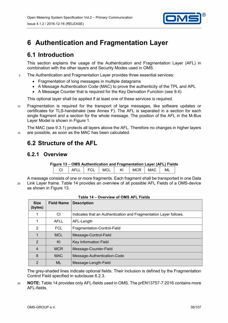
Open Metering System Specification Vol.2 – Primary Communication
Issue 4.1.2 / 2016-12-16 (RELEASE)
OMS-GROUP e.V. 38/107
6 Authentication and Fragmentation Layer
6.1 Introduction
This section explains the usage of the Authentication and Fragmentation Layer (AFL) in combination with the other layers and Security Modes used in OMS.
The Authentication and Fragmentation Layer provides three essential services: 5
Fragmentation of long messages in multiple datagrams
A Message Authentication Code (MAC) to prove the authenticity of the TPL and APL
A Message Counter that is required for the Key Derivation Function (see 9.4)
This optional layer shall be applied if at least one of these services is required.
Fragmentation is required for the transport of large messages, like software updates or 10
certificates for TLS-handshake (see Annex F). The AFL is separated in a section for each single fragment and a section for the whole message. The position of the AFL in the M-Bus Layer Model is shown in Figure 1.
The MAC (see 9.3.1) protects all layers above the AFL. Therefore no changes in higher layers are possible, as soon as the MAC has been calculated. 15
6.2 Structure of the AFL
6.2.1 Overview
Figure 13 – OMS Authentication and Fragmentation Layer (AFL) Fields
CI AFLL FCL MCL KI MCR MAC ML
A message consists of one or more fragments. Each fragment shall be transported in one Data Link Layer frame. Table 14 provides an overview of all possible AFL Fields of a OMS-device 20
as shown in Figure 13.
Table 14 – Overview of OMS AFL Fields
Size (bytes)
Field Name Description
1 CI Indicates that an Authentication and Fragmentation Layer follows.
1 AFLL AFL-Length
2 FCL Fragmentation-Control-Field
1 MCL Message-Control-Field
2 KI Key Information Field
4 MCR Message-Counter-Field
8 MAC Message-Authentication-Code
2 ML Message-Length-Field
The grey-shaded lines indicate optional fields. Their inclusion is defined by the Fragmentation Control Field specified in subclause 6.2.3.
NOTE: Table 14 provides only AFL-fields used in OMS. The prEN13757-7:2016 contains more 25
AFL-fields.
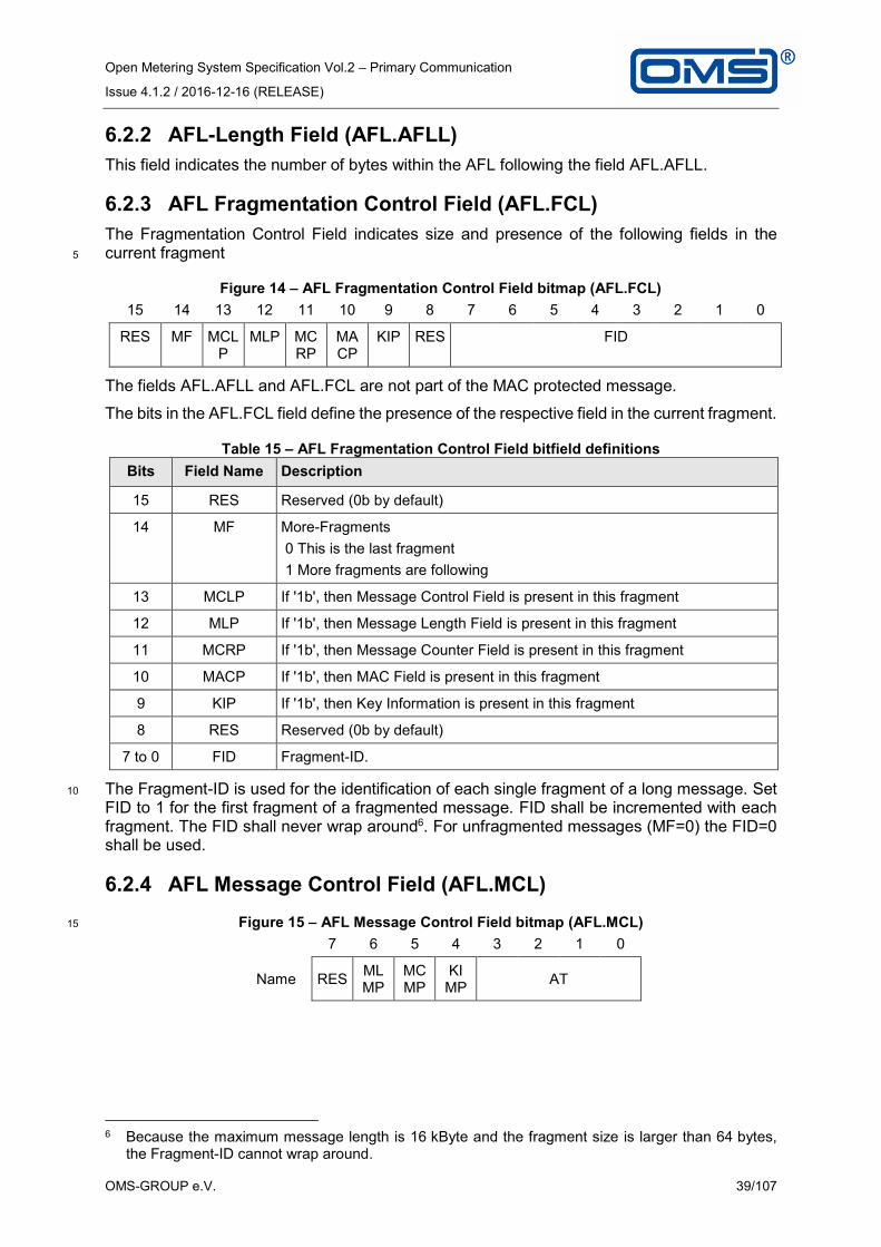
Open Metering System Specification Vol.2 – Primary Communication
Issue 4.1.2 / 2016-12-16 (RELEASE)
OMS-GROUP e.V. 39/107
6.2.2 AFL-Length Field (AFL.AFLL)
This field indicates the number of bytes within the AFL following the field AFL.AFLL.
6.2.3 AFL Fragmentation Control Field (AFL.FCL)
The Fragmentation Control Field indicates size and presence of the following fields in the current fragment 5
Figure 14 – AFL Fragmentation Control Field bitmap (AFL.FCL)
15 14 13 12 11 10 9 8 7 6 5 4 3 2 1 0
RES MF MCLP
MLP MCRP
MACP
KIP RES FID
The fields AFL.AFLL and AFL.FCL are not part of the MAC protected message.
The bits in the AFL.FCL field define the presence of the respective field in the current fragment.
Table 15 – AFL Fragmentation Control Field bitfield definitions
Bits Field Name Description
15 RES Reserved (0b by default)
14 MF More-Fragments
0 This is the last fragment
1 More fragments are following
13 MCLP If '1b', then Message Control Field is present in this fragment
12 MLP If '1b', then Message Length Field is present in this fragment
11 MCRP If '1b', then Message Counter Field is present in this fragment
10 MACP If '1b', then MAC Field is present in this fragment
9 KIP If '1b', then Key Information is present in this fragment
8 RES Reserved (0b by default)
7 to 0 FID Fragment-ID.
The Fragment-ID is used for the identification of each single fragment of a long message. Set 10
FID to 1 for the first fragment of a fragmented message. FID shall be incremented with each fragment. The FID shall never wrap around6. For unfragmented messages (MF=0) the FID=0 shall be used.
6.2.4 AFL Message Control Field (AFL.MCL)
Figure 15 – AFL Message Control Field bitmap (AFL.MCL) 15
7 6 5 4 3 2 1 0
Name RES MLMP
MCMP
KI MP
AT
6 Because the maximum message length is 16 kByte and the fragment size is larger than 64 bytes,
the Fragment-ID cannot wrap around.

Open Metering System Specification Vol.2 – Primary Communication
Issue 4.1.2 / 2016-12-16 (RELEASE)
OMS-GROUP e.V. 40/107
Table 16 – AFL Message Control Field bitfield definitions
Bits Field Name Description
7 RES Reserved
6 MLMP If '1b', then Message Length Field is present in the message
5 MCMP If '1b', then Message Counter Field is present in message
4 KIMP If '1b' then Key Information Field is present in message
3
AT Authentication-Type (see Table 17) 2
1
0
The bits 6 and 5 in the AFL.MCL field define the presence of the fields in the message.
Table 17 describes the usage of the AT-Field.
Table 17 – AT-Field of AFL .MCL
Value Authentication Type Length of Authentication Code
0 No authentication -
1...2 Reserved
3 Reserved
4 Reserved for AES-CMAC 128 (4 Byte)
5 AES-CMAC-128 (see 9.3.1) 8 bytes
6 Reserved for AES-CMAC -128 a (12 bytes)
7 Reserved for AES-CMAC -128 a (16 bytes)
8...15 Reserved
a Gateways should also support these authentication lengths to be future-proof.
The AFL.MCL field shall always be present in the first fragment. It shall not be present in any 5
following fragments of the same message.
6.2.5 AFL Key Information-Field (AFL.KI)
The Key Information field (see Table 18) enables the recipient of a message to identify the corresponding key. Details are described in subclause 9.4.
NOTE: The current applied Key-Version is essential for a Key-exchange procedure or the 10
first communicates from the gateway to the meter.
NOTE: The Key-ID can be also identified by the KI-subfield in TPL for messages using Security mode 7 (see 7.2.4.4).
Table 18 – AFL Key Information Field – bit field definitions
Bits Field Name Description
15 to 8 Key-Version The Key-Version identifies the applied key version
7 to 6 RES Reserved (0b be default)
5 to 4 KDF-Selection
The KDF-Selection identifies the applied Key Derivation Function, as specified in 9.4.
3 to 0 Key ID The Key-ID identifies the applied key, as specified in 7.2.4.4.

Open Metering System Specification Vol.2 – Primary Communication
Issue 4.1.2 / 2016-12-16 (RELEASE)
OMS-GROUP e.V. 41/107
The meter shall support an internal flag, called KI-Flag, to control the presence of the KI-Field. The KI-Flag is clear by default. If a gateway or any other communication partner applies AFL-Key Information Field in SND-UD or SND-UD2 then meter/actuator shall set KI-Flag. Otherwise, it shall clear the KI-Flag. The AFL.KI shall be present in RSP-UD as long as KI-Flag is set. 5
6.2.6 AFL Message Counter Field (AFL.MCR)
Figure 16 – AFL Message Counter Field bitmap
31 30 29 28 27 26 25 24 23 22 21 20 19 18 17 16
C[31 to 16]
15 14 13 12 11 10 9 8 7 6 5 4 3 2 1 0
C[15 to 0]
Table 19 – AFL Message Counter Field bitfield definitions
Bits Field Name Description
31 to 0 C A 32-Bit Field, which is strictly monotonously increasing. The counter shall be incremented before the generation of every new message. The counter never wraps. The initial value after manufacturing or after replacing the individual Master Key shall be 0.
The AFL.MCR shall be present in messages from/to meters, which are protected by security 10
methods using the KDF. See 9.5.4 for details on the requirements for the Message Counter.
If the Message Counter Field is used, the AFL.MCR field shall always be present in the first fragment. It shall not be present in any following fragments of the same message.
6.2.7 AFL MAC-Field (AFL.MAC)
The length of the MAC field depends on the selected option AFL.MCL.AT indicated by the 15
AFL.MCL field.
If the MAC-Field is used, the AFL.MAC field shall only be present in the last fragment of a message.
Check subclause 9.1 for the presence of the AFL.MAC in messages from meter or gateway.
6.2.8 AFL Message Length Field (AFL.ML) 20
This field declares the number of bytes that follows the AFL.ML to the end of the unfragmented message.
NOTE: The message length has to be calculated before the message is separated in several fragments.
Figure 17 – AFL Message Length Field bitmap 25
15 14 13 12 11 10 9 8 7 6 5 4 3 2 1 0
LEN[15:0]

Open Metering System Specification Vol.2 – Primary Communication
Issue 4.1.2 / 2016-12-16 (RELEASE)
OMS-GROUP e.V. 42/107
Table 20 – AFL Message Length Field bitfield definitions
Bits Field Name
Description
15 to 0 LEN The message length shall be limited to 16 kbytes. The message length contains the sum of all TPL fragments for one message. It does not include any AFL Fields.
The AFL.ML Message Length Field shall only be present in the first fragment of a fragmented message to indicate the total message length. For unfragmented messages, the AFL.ML shall not be used.
6.3 Conditions to apply an AFL 5
The AFL shall be applied
In each datagram of a fragmented message (SND-UD, RSP-UD)
In message types with application data (SND-NR, SND-UD, SND-UD2, SND-IR, RSP-UD) using Security profile B (see 9.1)
In each RSP-UD message, when KI-Flag is set (see 6.2.5) 10
In selected messages using Security profile C (see 9.1) with CMAC(see Annex F, F.2.3)

Open Metering System Specification Vol.2 – Primary Communication
Issue 4.1.2 / 2016-12-16 (RELEASE)
OMS-GROUP e.V. 43/107
7 Transport Layer
7.1 Overview
The Transport Layer has always a fixed frame structure as described in [EN 13757-3:2013]. It may transport either the meter Application Protocol according to [EN 13757-3:2013] (M-Bus), or alternatively [EN 13757-1:2014] (DLMS/COSEM communication primarily used by 5
electricity meters). Note that the CI field as the first byte of the Transport Layer distinguishes between these Application Protocol types and the frame structure. A gateway or a consumer display shall be able to handle all Application Protocol types at least to the extent that it can extract the values required for its function or application from the message. This specification part covers mainly the M-Bus variant. 10
NOTE: The gateway or the display needs to be able to parse any applied (M-Bus or COSEM or SML) Application Protocol into separate data points. However it is sufficient to “understand” i.e. decode only the required values stated in clause 8.
7.2 Common Part for all Transport Layers
7.2.1 General structure of the Transport Layer 15
The frame format of the Transport Layer is the same for all Application Protocols. The Transport Layer starts with a CI-Field, which indicates the main message function and the type of coding (i.e. the Application Protocol) used for the rest of the message. After the CI-Field a fixed sequence of bytes follows, which is called TPL-header. There are 3 types of TPL-headers. 20
The TPL-header structures are:
No TPL-header: This TPL-header type is used on the wired M-Bus for unencrypted messages. The next byte after the CI-Field is the first byte of the selected Application Protocol.
Short TPL-header: 25
The Short TPL-header is used only for wireless M-Bus. If the message contains such a “short” TPL-header the meter identification is taken from the Link Layer (see 3.1.3.1).
Long TPL-header: The Long TPL-header is used both for wired and wireless M-Bus. If the message contains such a “long” TPL-header, this TPL-header always contains (independent of 30
transmission direction) always the meter/actuator identification (see 3.1.3.3). For the wired M-Bus it will be used in case of encryption.
Every Short/Long TPL-header for wM-Bus contains:
Access number
Status Byte 35
Configuration Field
Depending on the selected Security Mode in the Configuration field additional bytes (like Configuration Field Extension or Decryption-Verification) may follow, before the Application Protocol starts. The structures of the Transport and Application Layer is pictured in Annex D. Table 1 in subclause 2.2 lists all supported CI-Fields and the related TPL-header types. 40

Open Metering System Specification Vol.2 – Primary Communication
Issue 4.1.2 / 2016-12-16 (RELEASE)
OMS-GROUP e.V. 44/107
7.2.2 Access Number
7.2.2.1 Access Number for wM-Bus
The Access Number together with the transmitter address is used to identify a datagram. It will be distinguished between:
Meter Access Number 5
Gateway Access Number
The Meter Access Number is generated by a meter/actuator. It shall be incremented by 1 (and only 1) with every synchronous transmission (see 4.3.2.1). Asynchronous transmissions shall always apply the Access Number of the last synchronous transmission. The Meter Access Number shall be applied to SND-NR, SND-IR, ACC-NR and ACC-DMD datagrams. If a 10
gateway accepts an ACC-DMD or an SND-IR from a meter/actuator it has to send an acknowledgement (ACK or CNF-IR) using the received Meter Access Number. The received Gateway Access Number has no impact on the stored Meter Access Number of the meter/actuator. After power up of the meter its value of the Access Number shall be set by a randomized initial value from 0 to 255. The Access Number of the meter shall not be resettable. 15
If an Extended Link Layer exists (see 5.3) then the Access Number of the Extended Link Layer shall be used for the synchronous transmission and Link acknowledgement. Each datagram can be identified by the Access number of the Extended Link Layer. The additional Access Number of the Transport Layer may differ from the Access Number of the ELL. This Transport Layer Access Number shall be used to indicate a new or old message content. Each message 20
can be identified by the Access Number of the Transport Layer. The (first) response (RSP-UD) of a (fragmented) message shall contain the TPL-Access number of the concerning request (REQ-UD2) and the (last) acknowledgement (ACK) of a (fragmented) message shall contain the TPL-Access Number of the concerning command (SND-UD).
NOTE: Other fragments may also contain a Transport Layer (with the TPL-Access number) 25
e.g. to provide an application error bit in the status byte.
The Gateway Access Number is generated by the gateway. It may be selected without any restrictions. However the gateway shall not use the same Access Number for a new datagram to the same meter/actuator again within 300 seconds. Each time the Gateway Access Number is changed, the gateway should alternate the FCB (see 5.2.3). 30
The meter/actuator shall not expect any specific order of Access Numbers in datagrams received from the gateway. It shall only distinguish between a new and an old datagram. The last received Access Number marks an old datagram. All other Access Numbers different from the last received one will be handled as the new Access Number. The content of the FCB (see 5.2.3) shall be ignored. When the meter/actuator finishes the Frequent Access Cycle (see 35
4.3.3) it shall clear the last received Gateway Access Number. After that any received Access Number will be handled as a new one.
If the meter/actuator receives an SND-NKE, SND-UD, SND-UD2, REQ-UD1 or REQ-UD2, it shall use the received Gateway Access Number of the ELL for its response or acknowledgement. The gateway may recognize an outstanding response or 40
acknowledgement by its own Access Number. Hence the meter/actuator repeats the last response or acknowledgement, if the gateway has sent the request or the command with the old ELL-Access Number again. Otherwise it shall generate a new datagram with the new ELL-Access Number received from the gateway.
NOTE: These rules to apply the Access number for wireless M-Bus conforms to [EN 13757-45
3:2013].
7.2.2.2 Access Number for M-Bus
For wired M-Bus the Access Number shall be conform to the [EN 13757-3:2013].

Open Metering System Specification Vol.2 – Primary Communication
Issue 4.1.2 / 2016-12-16 (RELEASE)
OMS-GROUP e.V. 45/107
7.2.3 Status Byte
It will be distinguished between:
Gateway Status (applied with CI-Field 53h, 55h, 5Ah, 5Bh, 5Fh, 60h, 61h, 64h, 65h, 6Ch, 6Dh or 80h)
Meter Status (applied with CI-Field 67h, 68h, 6Eh, 6Fh, 72h, 74h, 75h, 7Ah, 7Ch, 7Dh, 5
7Eh, 7Fh, 8Ah, 8Bh, 9Eh or 9Fh)
The Meter Status and Gateway Status shall be as defined in [EN 13757-3:2013]. This standard defines the meter status in subclause 5.10 and the gateway status in subclause 5.11.
The status field of the meter allows an Application Layer-response within an "ACK" message. (Note that this message itself only confirms the datagram reception). In this way, the bit 10
combination "any application error" shall be used to communicate a failure during the interpretation or the execution of a received command. Note that more detailed error description may be provided by an application error message (see 8.7). Thus it is recommended to send a REQ-UD2 whenever the bit combination "any application error" is set. The bit combination “any application error” shall be reset at the same time the application error 15
is cleared.
It is recommended, that the Low Power bit is set 15 months before the intended end of operation.
Details about other error conditions like "permanent error" may be provided in an Application Protocol (see 8.3.5.2). 20
7.2.4 Configuration Field
7.2.4.1 General
The Configuration Field shall be used as specified in [EN 13757-3:2013]. It declares the method of data encryption (Security Mode) and the length of encrypted data. The Security Mode is a part of the Configuration Field declared by the bits MMMMM. The Security Mode is 25
also determines the presence of the Configuration Field Extension and the meaning of all other bits (see 7.2.4.6).
NOTE: In former OMS-Specifications the Configuration Fields for Security Mode 7 and 13 were presented as 3 byte field. According to the new [prEN13757-7:2016] the Configuration Field is limited to two bytes. Additional bytes are called as Configuration Field Extension (CFE) and 30
are presented separately. Nevertheless, the byte order in the message is the same.
Table 21 shows the general structure of the Configuration Field and the position of the Security Mode.
Table 21 – General definition of the Configuration Field
MS
Bit
15
Bit
14
Bit
13
Bit
12
Bit
11
Bit
10
Bit
9
Bit
8
Bit
7
Bit
6
Bit
5
Bit
4
Bit
3
Bit
2
Bit
1
LS
Bit
0
Mode
specific
Mode
specific
Mode
specific
Mode
bit4
Mode
bit3
Mode
bit2
Mode
bit1
Mode
bit0
Mode
specific
Mode
specific
Mode
specific
Mode
specific
Mode
specific
Mode
specific
Mode
specific
Mode
specific
X X X M M M M M X X X X X X X X

Open Metering System Specification Vol.2 – Primary Communication
Issue 4.1.2 / 2016-12-16 (RELEASE)
OMS-GROUP e.V. 46/107
NOTE: In OMS-Spec. Vol2. Issue 3.0.1 the applied Mode Field includes only bit8 to bit11. Bit12 was marked as reserved. From this version on the Mode Field includes the bits from bit 8 to bit 12.
For OMS only the following Security Modes shall apply:
Security Mode 0 (no encryption) 5
Security Mode 5 (OMS standard for symmetric encryption)
Security Mode 7 (OMS standard for advanced symmetric encryption)
Security Mode 13 (OMS standard for asymmetric encryption)
NOTE: The Security Mode 4 is deprecated.
Subclause 9.2 describes the usage of these Security Modes. The next sub-sections describes 10
the structure of the mode specific Configuration Fields.
7.2.4.2 Configuration Field for Security Mode 0
The structure of the Configuration Field of Mode 0 is identical to Security Mode 5 (see Table 22). The M and N has to be set to 00h to indicate that no encryption is applied. See also subclause 9.2.2. 15
7.2.4.3 Configuration Field for Security Mode 5
Security Mode 5 is a symmetric encryption method using AES128 with CBC, a special Initialisation Vector and a persistent key (see 9.2.3).
The Initialisation Vector requires the usage of the Access Number. Be aware that the Initialisation Vector shall always apply the Access Number from Transport Layer whether or 20
not the Extended Link Layer exists.
Table 22 – Definition of the Configuration Field for Security Mode MMMM = 5
MS
Bit
15
Bit
14
Bit
13
Bit
12
Bit
11
Bit
10
Bit
9
Bit
8
Bit
7
Bit
6
Bit
5
Bit
4
Bit
3
Bit
2
Bit
1
LS
Bit
0
Bid
irectiona
l
Com
mun
ication
Accessib
ility
Synchro
no
us
Mode
bit4
Mode
bit3
Mode
bit2
Mode
bit1
Mode
bit0
Num
ber
of
encr.
blo
cks
Num
ber
of
encr.
blo
cks
Num
ber
of
encr.
Blo
cks
Num
ber
of
encr.
blo
cks
Conte
nt o
f M
essa
ge
Conte
nt o
f M
essa
ge
Repe
ate
d A
ccess
Hop C
ounte
r
B A S M M M M M N N N N C C R H
M is always 05h to mark AES128 with CBC and persistent key.
N contains the number of encrypted 16 Byte Blocks for CBC Mode. An N of 1111b specifies that partial encryption is disabled and no unencrypted data follow after the encrypted data. 25
This enables the possibility to encrypt very large fragmented messages. If N is set to 0000b, no encrypted data follow.
C declares the Content of Message (see 7.2.4.6).
B, A ,S ,R and H are used to control the Link (see 5.3.3).

Open Metering System Specification Vol.2 – Primary Communication
Issue 4.1.2 / 2016-12-16 (RELEASE)
OMS-GROUP e.V. 47/107
NOTE: A two byte sequence 2Fh, 2Fh (decryption verification) shall immediately follow the Configuration Field. The Decryption Verification Field is part of the Transport Layer.
NOTE: The Mode 5 may be used without Extended Link Layer and without Authentication and Fragmentation Layer (see 5.3.4).
7.2.4.4 Configuration Field for Security Mode 7 5
Security Mode 7 is a symmetric encryption method using AES128 with CBC and an ephemeral key (see 9.2.4). It is possible to identify up to 16 different keys using the Key-ID.
The Configuration Field (CF) to be used for Security Mode 07h is defined as follows:
Table 23 – Configuration Field for Security Mode 7
MS
Bit
15
Bit
14
Bit
13
Bit
12
Bit
11
Bit
10
Bit
9
Bit
8
Bit
7
Bit
6
Bit
5
Bit
4
Bit
3
Bit
2
Bit
1
LS
Bit
0
Conte
nt o
f M
essa
ge
Conte
nt o
f M
essa
ge
Reserv
ed for
Coun
ter
Siz
e
Mode
4
Mode
3
Mode
2
Mode
1
Mode
0
Num
ber
of
encr.
blo
cks
Num
ber
of
encr.
blo
cks
Num
ber
of
encr.
blo
cks
Num
ber
of
encr.
blo
cks
Reserv
ed for
Conte
nt In
dex
Reserv
ed for
Conte
nt In
dex
Reserv
ed for
Conte
nt In
dex
Reserv
ed for
Conte
nt
Index
C C 0 M M M M M N N N N 0 0 0 0
M is always 07h to mark AES128 with CBC and ephemeral key. 10
C declares the Content of Message (see 7.2.4.6).
N contains the number of encrypted 16 Byte Blocks for CBC Mode. An N of 1111b specifies that partial encryption is disabled and no unencrypted data follow after the encrypted data. This enables the possibility to encrypt very large fragmented messages. If N is set to 0000b, no encrypted data follow. 15

Open Metering System Specification Vol.2 – Primary Communication
Issue 4.1.2 / 2016-12-16 (RELEASE)
OMS-GROUP e.V. 48/107
Security Mode 7 requires a Configuration Field Extension according to Table 24.
Table 24 – Configuration Field Extension for Security Mode 7
MS
Bit
7
Bit
6
Bit
5
Bit
4
Bit
3
Bit
2
Bit
1
LS
Bit
0
Reserv
ed
Reserv
ed for
Vers
ion
KD
F-S
ele
ction
KD
F-S
ele
ction
Key-I
D
Key-I
D
Key-I
D
Key-I
D
0 0 D D K K K K
K selects the Key ID for Encryption. Only the use of K=0 (Master Key MK) is allowed. Other Key-IDs are reserved for future use.
D is 01b to mark Key Derivation Function as defined in subclause 9.4. 5
NOTE: A two byte sequence 2Fh, 2Fh (decryption verification) shall immediately follow the Configuration Field Extension. The Decryption Verification Field is part of the Transport Layer.
NOTE: The usage of the mode 7 on wireless M-Bus requires the Extended Link Layer (ELL), which covers the necessary Link Layer control elements like Hop Counter Bit, Synchronous Bit and Bidirectional Access Bit. 10
7.2.4.5 Configuration Field for Security Mode 13
Security Mode 13 is an asymmetric encryption method using TLS (see Annex F).
Table 25 – Configuration Field for Security Mode 13
Bit
15
Bit
14
Bit
13
Bit
12
Bit
11
Bit
10
Bit
9
Bit
8
Bit
7
Bit
6
Bit
5
Bit
4
Bit
3
Bit
2
Bit
1
LS
Bit
0
Conte
nt o
f M
essa
ge
Conte
nt o
f M
essa
ge
Reserv
ed
Mode
4
Mode
3
Mode
2
Mode
1
Mode
0
Num
ber
of
encry
pte
d b
yte
s
Num
ber
of
encry
pte
d b
yte
s
Num
ber
of
encry
pte
d b
yte
s
Num
ber
of
encry
pte
d b
yte
s
Num
ber
of
encry
pte
d b
yte
s
Num
ber
of
encry
pte
d b
yte
s
Num
ber
of
encry
pte
d b
yte
s
Num
ber
of
encry
pte
d b
yte
s
C C 0 M M M M M N N N N N N N N
M is always 0Dh (13 decimal) to declare an Encryption with TLS
NOTE: The applied TLS-Version can be retrieved from the TLS-Header 15

Open Metering System Specification Vol.2 – Primary Communication
Issue 4.1.2 / 2016-12-16 (RELEASE)
OMS-GROUP e.V. 49/107
C declares the Content of message (see 7.2.4.6).
N contains the number of encrypted bytes. It indicates the number of bytes following the Configuration Field which are covered by the Protocol indicated by Protocol type (TLS). N is limited to 255.
NOTE: For larger sizes the exact number of bytes (minus the TLS header size 5 Bytes) can 5
be found in the 4th and 5th Byte of the TLS header.
Security Mode 13 requires a Configuration Field Extension according to Table 26.
Table 26 – Configuration Field Extension for Security Mode 13 M
SB
it 2
3
Bit
22
Bit
21
Bit
20
Bit
19
Bit
18
Bit
17
Bit
16
Reserv
ed
Reserv
ed
Reserv
ed
Reserv
ed
Pro
toco
l T
ype 3
Pro
toco
l T
ype 2
Pro
toco
l T
ype 1
Pro
toco
l T
ype 0
0 0 0 0 P P P P
P defines the Protocol Type (see Annex F).
NOTE: No Decryption Verification Field follows the Configuration Field. 10
NOTE: The usage of the mode 13 on wireless M-Bus requires the application of the Extended Link Layer.
7.2.4.6 Special bits of the Configuration Field
Bits CC are used to describe the content of the message
Table 27 – Contents of meter message (from the meter/actuator to the gateway) 15
Conf. Bit 3
Conf. Bit 2
Contents of the message
0 0 Standard data message with unsigned variable meter data
0 1 Reserved for message prioritisation
1 0 Static message (consists of parameter, OBIS definitions and other data points which are not frequently changed – see also 4.3.2.4).
1 1 Reserved for future extensions
Table 28 – Contents of gateway authentication (from the gateway to the meter/actuator)
Conf. Bit 3
Conf. Bit 2
Contents of data point authentication
0 0 Standard command message
0 1 Reserved for command prioritisation
1 0 Reserved
1 1 Reserved for future extensions

Open Metering System Specification Vol.2 – Primary Communication
Issue 4.1.2 / 2016-12-16 (RELEASE)
OMS-GROUP e.V. 50/107
The Configuration Field of Security Mode 5 and 0 support the Link Control Bits B, A, S, R, and H. These bits are also provided by the Extended Link Layer.
If no Extended Link Layer exist then
the bit S shall be used as described in subclause 4.3.2.1
bits B and A shall be used as described in subclause 4.3.3.1 5
bits H and R shall be used as describer in subclause 5.3.3.
Otherwise, these Link Control Bits in the Configuration field should be set to zero.
If the ELL exists, the Link Control Bits in the TPL shall be ignored (see 5.3.3).
The subclause 5.3.4 describes the conditions whether or not an Extended Link Layer exists.
7.3 Conditions to apply the Transport Layer 10
The Transport Layer is required for Message types with application data. Also Message types without application data uses the TPL to provide following services:
Meter address,
Access number of the message,
Reception level of the meter or 15
Application error of the received message
Encryption of application data
The meter/actuator shall apply the TPL for the Message types according to Table 29.
Table 29 — Usage of TPL depending on Message type
Direction Message type Presence TPL wired M-Bus
Presence TPL wireless M-Bus
Maste
r to
sla
ve
SND-NKE Never Always
SND-UD Optional a Always b
SND-UD2 Not applicable Always
REQ-UD1 Never Always
REQ-UD2 Never Always b
ACK Not applicable Always
CNF-IR Not applicable Always
Sla
ve
to m
aste
r
SND-NR Not applicable Always
SND-IR Not applicable Always
ACC-NR Not applicable Optional d
ACC-DMD Not applicable Always
ACK Never Always c
NACK Not applicable Optional d
RSP-UD Always Always b
a In case of encryption the TPL is necessary
b For a fragmented message sequence the TPL shall only be in the first datagram (see 7.2.2.1) c For a fragmented message sequence the TPL shall only be in the last datagram (see 7.2.2.1
and L.4) d In case ELL is not there, the TPL shall be provided (see 5.3.4)
20

Open Metering System Specification Vol.2 – Primary Communication
Issue 4.1.2 / 2016-12-16 (RELEASE)
OMS-GROUP e.V. 51/107
8 Application Protocols
8.1 Overview
After the Transport Layer the Application Protocol starts immediately.
Possible Application Protocols for meter application data are:
M-Bus (see 8.3) 5
DLMS (see 8.4)
SML (see 8.5)
Beside these Application Protocols for meter data exchange, there exist some more Application Protocols for special services:
Clock Synchronisation Protocol (see 8.6) 10
Application Error Protocol (see 8.7)
Security Management Protocol (see 0)
Security Information Transfer Protocol (see Annex F)
Alarm Protocol (refer to [EN 13757-3:2013] Annex D)
and more (see Table 1) 15
8.2 Required Values and their Resolution and Accuracy
For the Open Metering System each message for billing purposes shall at least contain the current meter index with the meter accuracy and sufficient resolution for billing. Each message for consumer information shall contain sufficient information and accuracy to enable the gateway to display power respectively flow with sufficient accuracy and resolution. 20
For that reason the OMS-Meter shall be conform to Annex L.7 of [EN 13757-3:2013].
If power or flow values are transmitted and the applied averaging interval is smaller than the nominal transmission interval then the data point Averaging Duration should be transmitted additionally.
NOTE: The transmission of the Averaging Duration in the static datagram (see 4.3.2.4) will be 25
sufficient.
8.3 M-Bus Application Protocol
8.3.1 General
The M-Bus Application Protocol is described in [EN 13757-3:2013]. To ensure interoperability, the use of the M-Bus Application Protocol in OMS is restricted by the following additional rules. 30
8.3.2 OMS-Data Point List
The Annex B list all harmonised M-Bus-Data points in the OMS-Data point list (OMS-DPL). This list consists of a VIB-Type List (VTL) and an M-Bus-Tag List. (MBTL)
The VIB-Type List provides all supported combinations of VIF's and VIFE's applied conform to this specification. 35
The M-Bus-Tag List provides all M-Bus-Tags applicable to conform to this specification. An M-Bus-Tag is an abstract presentation of a single M-Bus data point or a set of M-Bus-Data points which differs by the scaler (see VIB-Type List of Annex B) or resolution.

Open Metering System Specification Vol.2 – Primary Communication
Issue 4.1.2 / 2016-12-16 (RELEASE)
OMS-GROUP e.V. 52/107
8.3.3 OMS-Gateway
OMS-Gateways shall support all M-Bus data points listed in the OMS-DPL (see Annex B).
The standard load profile and the M-Bus compact profile according to [EN 13757-3:2013], Annex I shall be supported, as well, provided that the underlying single M-Bus data points use the exact DIB/VIB coding given by the OMS-DPL. See Annex G for examples for the 5
conversion of load profiles to single data points.
M-Bus data points compliant with [EN 13757-3:2013], but not listed in the OMS-DPL, may optionally be supported by OMS-Gateways.
8.3.4 OMS meter
Meters shall provide all M-Bus data points that are marked as mandatory (M) or alternative 10
(Ax) in the OMS-DPL for the meter with the respective Device Type. The exact DIB/VIB coding given in the Annex B shall be used.
Note that a data point consisting of a combination of tariff, subunit, storage number, function code, final DIFE and VIFE shall be unique within a message.
NOTE: Several data points which differentiate for example by the data type (INT/BCD) only 15
are not allowed.
At least one of the alternative data points (Ax – see OMS-DPL) marked with the identical number (x) shall be provided by the meter. If multiple alternatives are provided in one message, all data points shall provide the required accuracy and resolution.
If a meter provides additional M-Bus data points marked as optional (O) in the OMS-DPL it 20
shall use the exact DIB/VIB coding given there.
Meters may additionally use the standard load profile or the M-Bus compact profile according to [EN 13757-3:2013], Annex I. The underlying single M-Bus data points shall use the exact DIB/VIB coding given by the OMS-DPL. See Annex G for examples for the conversion of load profiles to single data points. 25
M-Bus data points that are listed in the OMS-DPL shall not be used in alternative or manufacturer specific sense.
Additional M-Bus data points that are not explicitly listed in the OMS-DPL, but comply with [EN 13757-3:2013], may optionally be provided by the OMS-meter. But these additional data points shall not be used as replacement of present data points in the OMS-DPL. 30
8.3.5 Usage of specific data points
8.3.5.1 Date, time and intervals
For the averaging time interval of power or flow values the data point “averaging duration” shall be used (see 8.2).
For an uncorrelated transmission (refer to Annex L subclause L.7.3.4 in [EN 13757-3:2013] 35
the elapsed time between measurement and transmission shall be coded with the data point “Actuality Duration”.
The nominal transmission interval used for synchronous transmission should be declared in installation datagrams (if available) with the data point “period of nominal data transmissions” (in seconds or minutes). 40

Open Metering System Specification Vol.2 – Primary Communication
Issue 4.1.2 / 2016-12-16 (RELEASE)
OMS-GROUP e.V. 53/107
8.3.5.2 Management data
Details about the error state indicated by Status Byte (see 7.2.3) shall be coded with the data point “Error flags” or optional with “Error flags (standard)".
If a sequence number is needed (to prevent zero consumption – refer to [EN 13757-3:2013], 5.9.2) it shall be coded as data point "Unique message identification”. 5
For meter management the reception level of a received radio device can be transmitted with the data point “Reception or noise level” (refer to [EN 13757-3:2013] Table 28, footnote d).
If this data point is used together with the Function field 10b in DIF it declares present quality limit of the reception level, which was exceeded by the received radio device. Example: 21h FDh 71h 9Ch marks a reception level > -100 dBm. 10
If this data point is used together with the Function field 11b it declares the typical noise level detected by this radio device. Example: 31h FDh 71h 9Fh means a noise level of -97 dBm.
8.3.6 OBIS code
The OBject Identification System (OBIS) defines the identification codes for commonly used data items in metering equipment. 15
These identification codes from DLMS-UA Blue Book are used for identification of:
• logical names of the instances of the Interface classes, the objects
• data transmitted through communication lines
• data displayed on the metering equipment
OBIS-codes in addition are used for the market communication of different contract partners 20
for the standardised exchange of metering values. M-Bus coded metering data needs a mapping to the relevant COSEM object instantiation with OBIS code identifying the appropriate information. The Annex A defines a List of OBIS codes (LOC) as subset of M-Bus-Tags from the OMS-DPL and the assigned OBIS codes. An OMS-Gateway which is converting M-Bus data points to another Application Protocol shall add the respective OBIS code from the list. 25
If a meter/actuator uses an M-Bus data point which is not listed in the OMS-DPL, but is required for billing purposes, the OBIS declaration should be transmitted by the meter/actuator itself. A radio device should transmit this OBIS declaration by a static message (see 4.3.2.4). The OMS-Gateway then adds this OBIS declaration to the default OBIS conversion-table. The OBIS declaration via the M-Bus Application Protocol is described in [EN 13757-3:2013], 30
Annex O.2.
8.3.7 Descriptors
M-Bus messages may contain several data points with the same VIB. They are separated using different Storage numbers, Tariff numbers or Subunits (coded in the DIB). This allows the gateway to distinguish and group these data points e.g. using same Storage number. There 35
is however no information about the intention of such data points.
Data points listed in the Annex A can be interpreted by the assignment to the given OBIS-Code (e.g. HC1!D and DT2!D, coded with Storage number 1, are defined as value at due date). Other data points (e.g. coded with Storage number 2) provide no information about the meaning and their interpretation may vary between manufactures. 40
Descriptor data points (defined in Annex K) should be used to add a meaning to every data point group (e.g. all data points using Storage number 2 are used for monthly values). This enables the user to interpret the meter data points correctly.
For some data points the usage of descriptors is mandatory (see Annex K).

Open Metering System Specification Vol.2 – Primary Communication
Issue 4.1.2 / 2016-12-16 (RELEASE)
OMS-GROUP e.V. 54/107
In case a descriptor is required, it shall be sent in each data message, which contains a data point that needs the descriptor, or in each static message (see 4.3.2.4) of this meter/actor.
8.4 DLMS Application Protocol
The DLMS Application Protocol for CEN meters is described in [EN 13757-1:2014], [EN 62056-6-1:2013] and [DLMS UA]. 5
8.5 SML Application Protocol
The SML Application Protocol is described in document [SML-spec].
8.6 Clock Synchronisation Protocol
The gateway shall provide the correct time (UTC) for every assigned bidirectional meter/actuator, unless otherwise specified in Annex E. 10
As long as no encryption key of the meter is provided, the gateway may leave out the clock synchronisation for this meter/actuator. The clock synchronisation shall be provided periodically and on event. In the following cases, a clock synchronisation shall be applied:
Once every day (as long as the gateway has a valid time)
When the gateway gets back to the valid time 15
After the installation of a new meter or actuator
After a communication interrupt for more than 24 hours
The clock synchronisation is a service of the gateway. The usage of this service depends only on the meter/actor itself and is not mandatory. The meter/actuator shall accept the synchronisation of the clock only if the time is transmitted in an encrypted way (valid for both 20
wired and wireless communication).
The [EN 13757-3:2103] Annex H.3 describes the transmission of the clock synchronisation to the meter/actuator.
NOTE: The synchronisation of the meter clock may be in conflict with national laws. Check Annex E for details. 25
8.7 Application Error Protocol
When a meter/actuator detects a failure during the interpretation or the execution of a received command it shall generate an application error. The presence of an application error should be announced in the Status field (see 7.2.3). For the wireless M-Bus the application error may be requested by the gateway with a REQ-UD2 as long as the Frequent Access Cycle is still 30
active (see 4.3.3). When the Frequent Access Cycle is over the meter/actuator shall discard the application error and reply the normal response to the next REQ-UD2. For the wired M-Bus the application error remains valid until the next Application reset/select.
The application error shall be transmitted with the generic Application Error Protocol as defined in [EN 13757-3:2013], 8.3 (see also Table 1 in 2.2). 35
Application errors shall be transmitted unencrypted. There is an exception for Security profile C (see 9.1). Details are described in Annex F.
NOTE: The Application Error Protocol can only be used for bidirectional communication.

Open Metering System Specification Vol.2 – Primary Communication
Issue 4.1.2 / 2016-12-16 (RELEASE)
OMS-GROUP e.V. 55/107
8.8 Security Management Protocol
The Security Management Protocol provides services to establish and manage session based secured data transfer channels like TLS. It is initiated with specific CI-Fields (see Table 1). After a successful establishment the application data (e.g. M-Bus coded metering data initiated with CI = 72h) can be transferred within this secured channel. 5
The structure of the security management data depends on the Security Mode defined in the TPL Configuration Field and other Security Mode specific fields in the Configuration Field/ Configuration Field Extension. The first implementation of the Security Management Protocol is defined for the Security Mode 13 (see 9.2.5), which is needed for the OMS Security profile C using Transport Layer Security (TLS). Details are described in Annex F. 10

Open Metering System Specification Vol.2 – Primary Communication
Issue 4.1.2 / 2016-12-16 (RELEASE)
OMS-GROUP e.V. 56/107
9 Communication security
9.1 Overview
To protect the privacy of the consumer, all wireless communication containing consumption data shall be encrypted. For wired communication, the encryption is optional.
However if encryption for the communication channel is enabled not all messages need to be 5
encrypted. Table 30 lists for each protocol / layer whether or not the encryption is required, possible or not allowed. Messages without a CI-Field are generally not encrypted.
Even if encryption for an application protocol is required, some data points like Identification or Fabrication number need to be transmitted unencrypted. Annex B.2 lists for each M-Bus data point whether or not the encryption is required, possible or not allowed. 10
Annex F lists requirements for encryption of TLS-handshake messages.
Annex E lists additional national requirements.
Table 30 – Compulsory encryption of application protocols
CI-Field Protocol / Layer Encryption
50h Application Reset or Select N/A
53h Application Reset or Select 51h Command (M-Bus) N/A
5Ah, 5Bh Command (M-Bus) 5Fh Command (TLS-HS) see Annex F
60h, 61h a Command (DLMS) 64h, 65h a Command (SML) 52h Selection of Device N/A
6Ch, 6Dh Time Sync 6Eh, 6Fh b Application Error 70h Application Error N/A
71h Alarm N/A
74h, 75h Alarm 72h, 7Ah Response (M-Bus) see Annex B.2
7Ch, 7Dh a Response (DLMS) 7Eh, 7Fh a Response (SML) 80h, 8Ah, 8Bh Pure Transport Layer N/A
8Ch, 8Eh Extended Link Layer N/A
90h Authentication and Fragmentation Layer N/A
9Eh, 9Fh Response (TLS-HS) see Annex F
B8h Set baud rate to 300 baud N/A
BBh Set baud rate to 2400 baud N/A
BDh Set baud rate to 9600 baud N/A

Open Metering System Specification Vol.2 – Primary Communication
Issue 4.1.2 / 2016-12-16 (RELEASE)
OMS-GROUP e.V. 57/107
Table 30 (continued)
CI-Field Protocol / Layer Encryption
Encryption is mandatory
Encryption is optional (Manufacturer specific)
Encryption is not allowed
N/A Not applicable
a These commands/responses encrypt and authenticate data using either the security services of AFL/TPL (according this specification) or APL specific security methods.
b For Security profile C the encrypted transmission of application errors is allowed For details see Annex F.
The usage of a MAC (see 9.3) ensures the integrity and the authenticity of the transferred data.
A persistent key is normally inserted by an operator action and is intended for a long validity time. It can be used for encryption, authentication or key derivation. For some cipher methods 5
a key is derived from the persistent key. Such a key is called ephemeral key and is used for encryption or authentication. It has a short validity time or is used only once. Table 31 provides an overview about the supported security profiles. Each profile presents a valid combination of the encryption method, message authentication and the length and type of used key.
Table 31 – OMS Security profiles 10
Profile Encryption Authentication Key
No Security profile
No encryption (ENC-Mode 0) a
No MAC (MAC-Mode AT=0) b
No key
Security profile A
AES128-CBC (ENC-Mode 5) a
No MAC (MAC-Mode AT=0) b
128 bit persistent symmetric key
Security profile B
AES128-CBC (ENC-Mode 7) a
CMAC (8 Byte trunc.) (MAC-Mode AT=5) b
128 bit ephemeral symmetric key (derived by KDF)
Security profile C
TLS 1.2 (ENC-Mode 13) a HMAC (TLS1.2) and additional CMAC (8 Byte trunc.) (MAC-Mode AT=5) b for communication establishment.
256 bit elliptic curve key
(384 bit optional) for TLS
and
128 bit ephemeral symmetric key (derived by KDF) for CMAC c
a Declared in Configuration Field CF (see 7.2.4) b Declared in AFL.MCL (see 6.2.4). If AFL is not present the default interpretation is AT=0 c During the TLS-handshake the usage of the CMAC is also required. However the normal data exchange of Mode 13 applies the HMAC of the TLS protocol for message authentication.
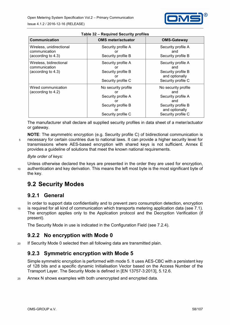
Open Metering System Specification Vol.2 – Primary Communication
Issue 4.1.2 / 2016-12-16 (RELEASE)
OMS-GROUP e.V. 58/107
Table 32 – Required Security profiles
Communication OMS meter/actuator OMS-Gateway
Wireless, unidirectional communication (according to 4.3)
Security profile A or
Security profile B
Security profile A and
Security profile B
Wireless, bidirectional communication (according to 4.3)
Security profile A or
Security profile B or
Security profile C
Security profile A and
Security profile B and optionally
Security profile C
Wired communication (according to 4.2)
No security profile or
Security profile A or
Security profile B or
Security profile C
No security profile and
Security profile A and
Security profile B and optionally
Security profile C
The manufacturer shall declare all supplied security profiles in data sheet of a meter/actuator or gateway.
NOTE: The asymmetric encryption (e.g. Security profile C) of bidirectional communication is necessary for certain countries due to national laws. It can provide a higher security level for 5
transmissions where AES-based encryption with shared keys is not sufficient. Annex E provides a guideline of solutions that meet the known national requirements.
Byte order of keys:
Unless otherwise declared the keys are presented in the order they are used for encryption, authentication and key derivation. This means the left most byte is the most significant byte of 10
the key.
9.2 Security Modes
9.2.1 General
In order to support data confidentiality and to prevent zero consumption detection, encryption is required for all kind of communication which transports metering application data (see 7.1). 15
The encryption applies only to the Application protocol and the Decryption Verification (if present).
The Security Mode in use is indicated in the Configuration Field (see 7.2.4).
9.2.2 No encryption with Mode 0
If Security Mode 0 selected then all following data are transmitted plain. 20
9.2.3 Symmetric encryption with Mode 5
Simple symmetric encryption is performed with mode 5. It uses AES-CBC with a persistent key of 128 bits and a specific dynamic Initialisation Vector based on the Access Number of the Transport Layer. The Security Mode is defined in [EN 13757-3:2013], 5.12.6.
Annex N shows examples with both unencrypted and encrypted data. 25

Open Metering System Specification Vol.2 – Primary Communication
Issue 4.1.2 / 2016-12-16 (RELEASE)
OMS-GROUP e.V. 59/107
9.2.4 Advanced symmetric encryption with Mode 7
Advanced symmetric encryption is performed with mode 7. It uses AES-CBC with an ephemeral key of 128 bits and a static Initialisation Vector IV = 0 (16 Bytes of 00h).
The ephemeral key shall be generated with a Key Derivation Function (KDF) which is described in subclause 9.4. 5
For ensuring the integrity and authenticity the CMAC as described in subclause 9.3.1 shall be used.
Applying the Security Mode 7 always requires the usage of the AFL (see clause 6), since the Message Counter C (see 9.5.4) is needed for the KDF and transmitted in the AFL.
The data to be encrypted shall be padded to a multiple of 16 bytes before encryption. The 10
padding value is 2Fh.
Annex N shows examples with both unencrypted and encrypted data.
9.2.5 Asymmetric encryption with Mode 13
Mode 13 describes an asymmetric encryption method based on Transport Layer Security (TLS). For details see Annex F. 15
NOTE: It should be noted that the TLS (Transport Layer Security) according to Security profile C is independent from the KDF and CMAC. Nevertheless the CMAC is required for the TLS-handshake procedure to protect it against DoS attacks7.
9.3 MAC-Generation
9.3.1 CMAC (AES 128 – 8 Byte truncated) 20
The authentication of the message is supported by the AFL (option AT=5 - see 6.2.4) using the MAC. This MAC shall be calculated as specified in AES128 for Crypto-Message-Authentication (CMAC-AES128) according to [RFC4493]. The MAC shall be calculated as follows: AFL.MAC = CMAC (Kmac/Lmac, AFL.MCL || AFL.MCR[7..0] || 25
AFL.MCR[15..8] || AFL.MCR[23..16] || AFL.MCR[31..24] || {
AFL.ML[7..0] || AFL.ML[15..8] || } NextCI || ... || Last Byte of
message)
The presence of the AFL.ML field depends on the selection bits in the AFL.MCL field.
The MAC shall be calculated after the encryption. The MAC of a received message shall be 30
verified before decryption.
An example is given in Annex N.
For a transmission from gateway to meter the key Lmac is used, for a transmission from meter to gateway the key Kmac is used (see key calculation in subclause 9.5.7).
The 16 byte result of this CMAC-function shall be truncated to 8 byte as defined in [RFC4493]. 35
In deviation to the usual transmission order for octet strings on the M-Bus, the MSB of the MAC shall be transmitted as first byte, the LSB as last.
9.3.2 HMAC (TLS1.2)
The TLS1.2 requires an HMAC for the authentication of the payload. TLS message authentication is part of the TLS protocol. See Annex F for details. 40
7 A denial-of-service (DoS) attack is an attempt to make a service unavailable to its intended users.

Open Metering System Specification Vol.2 – Primary Communication
Issue 4.1.2 / 2016-12-16 (RELEASE)
OMS-GROUP e.V. 60/107
9.4 Key-ID
Each Key is defined for a specific purpose. The Key-ID is used to identify the key and its usage. Table 33 list available Key-ID's.
NOTE: Keys used for security services in TPL and AFL can apply only Key-ID-numbers from 00h to 0Fh. 5
Table 33 – Predefined OMS-Key-ID
NOTE: A key used for replacement of an existing key, applies the same Key-ID but a different Key Version (see 6.2.5).
9.5 Key Derivation Function
9.5.1 General 10
The encryption of application data and the MAC shall be based on an ephemeral key, which is used for one message only. The ephemeral key shall be generated using the Key Derivation Function defined below. The Key Derivation Function shall also apply to the CMAC-Function according to [RFC4493]. There are 5 input values to the KDF specified in 9.5.2 to 9.5.6.
9.5.2 Individual Master Key (MK) 15
Before each transmission two ephemeral keys Kenc (for encryption) and Kmac (for authentication) are derived from the individual Master Key MK. There are two sets of key pairs (one set for the meter Kenc/Kmac and one set for the gateway Lenc/Lmac).
9.5.3 Derivation Constant (D)
The constant is used to derive different Keys for both Encryption and Authentication as well as 20
for the two directions -from and to the meter.
Table 34 – Constant D for the key derivation
D Used for
00h Encryption from the meter (Kenc)
01h MAC from the meter (Kmac)
Techno-logy
Key-ID Usage Responsible
Sym
metr
ic
00h Master-Key (MK) OMS-group
01h to 07h Manufacturer specific AFL-/TPL-Keys Manufacturer
08h to 0Fh Reserved for harmonised AFL-/TPL-Keys
OMS-group
10h to 2Fh Reserved for harmonised APL-Keys OMS-group
30h to 4Fh Manufacturer specific APL-Keys Manufacturer
50h to 7Fh Reserved -
Asym
metr
ic
80h to 9Fh Defined in Annex F OMS-group
A0h to BFh Reserved for harmonized Keys OMS-group
C0h to EFh Manufacturer specific Keys Manufacturer
F0h to FFh Reserved -

Open Metering System Specification Vol.2 – Primary Communication
Issue 4.1.2 / 2016-12-16 (RELEASE)
OMS-GROUP e.V. 61/107
10h Encryption from the gateway (Lenc)
11h MAC from the gateway (Lmac)
9.5.4 Message Counter
9.5.4.1 Overview
The changing keys are generated by inclusion of a strictly monotonously increasing (non-secret) counter in the KDF. This counter is transmitted in the AFL.MCR field (see 6.2.6). The Message Counter maintained and transmitted by the meter is named CM, the Message Counter 5
maintained and transmitted by the gateway is named CGW.
A copy of this message counter stored by the receiver of the message is marked as C’ respectively C’’.
The following counters are needed for data exchange: — CM Meter counter used by the meter as transmission counter; 10
— CGW Communication partner counter used by the communication partner as transmission counter;
— C’GW unverified copy of communication partner counter used by the meter;
— C’M unverified copy of meter counter used by the communication partner;
— C’’M verified copy of meter counter used by the communication partner; 15
The meter counter CM is the leading counter in the system.
NOTE: The message counter is required for Security profile B and C (see 9.1)!
An example for the handling of the Message Counter is provided in Annex J.
9.5.4.2 Message counter handling in a meter
CM is used for the derivation of keys applicable to messages transmitted from the meter to the 20
gateway.
The initial value of CM is 0. The meter shall increment CM by 1 prior to generating an authenticated and encrypted message.
CM shall be updated if an authenticated message counter CGW from gateway was received as shown in Figure 18. 25
When the counter CM reaches the maximum value FFFFFFFFh it shall not wrap around with next increment. In this case the meter should stop any transmission.
In case the individual Master Key (Key-ID K=0) of meter is changed the counter CM shall be reset to initial value.
Figure 18 shows the handling of message counter in a meter for both transmitting and receiving 30
a message.

Open Metering System Specification Vol.2 – Primary Communication
Issue 4.1.2 / 2016-12-16 (RELEASE)
OMS-GROUP e.V. 62/107
Figure 18 – Handing of the message counter in the meter

Open Metering System Specification Vol.2 – Primary Communication
Issue 4.1.2 / 2016-12-16 (RELEASE)
OMS-GROUP e.V. 63/107
9.5.4.3 Message counter handling in a gateway
CGW is used for the derivation of keys applicable to messages transmitted from the gateway to the meter.
NOTE: The gateway supports an independent message counter CGW for each connected meter. 5
The initial value of CGW for each meter is 0.
CGW shall be updated if an authenticated message counter CM from meter was received as shown in Figure 19.
The gateway shall increment CGW prior to generating an authenticated and encrypted message. The increment shall not exceed the value of 100. 10
When the counter CGW reaches the maximum value FFFFFFFFh it shall not wrap around with next increment. In this case the gateway should stop any transmission to this meter.
When the gateway receives a message counter CM ≥FFFF0000h it should set the meter in error condition to trigger a service action (e.g. Master Key exchange) before the message counter of meter reach maximum value. 15
Figure 19 shows the handling of message counter in a gateway for both transmitting and receiving a message.

Open Metering System Specification Vol.2 – Primary Communication
Issue 4.1.2 / 2016-12-16 (RELEASE)
OMS-GROUP e.V. 64/107
Figure 19 – Handing of the message counter in the gateway
NOTE: Because of the short time window (2ms) for replying to a wM-Bus T-Mode datagram a gateway may calculate the Encryption key and Authentication key in advance, based on the assumption of an Message Counter value (CM’’). 5

Open Metering System Specification Vol.2 – Primary Communication
Issue 4.1.2 / 2016-12-16 (RELEASE)
OMS-GROUP e.V. 65/107
9.5.5 Meter-ID
For messages from the meter to the gateway which use a Short TPL-header, (like CI=7Ah; refer to [EN 13757-3:2013]) the ID_0 to ID_3 corresponds to the LSB to MSB of the Link Layer Identification Number of the meter. For messages with Long TPL-header (like CI=72h) the ID_0 to ID_3 corresponds to LSB to MSB of the Application Layer Identification Number of the 5
meter.
For messages from the gateway to the meter the Long TPL-header is always used. The ID_0 to ID_3 corresponds to the LSB to MSB of the Application Layer Identification Number (address) of the meter (not the gateway!).
9.5.6 Padding 10
To avoid the generation of the K2 (refer to [RFC4493]) in the KDF, the remaining bytes of the 16 byte block are filled with a padding sequence. For the generation of Kmac, Lmac and Kenc, Lenc the padding is fixed and consists of seven octets each containing the value of 07h according to the rule that the input to the MAC shall be padded with (16-l mod 16) bytes with value (16-l mod 16), where l equals the byte length of the input. 15
9.5.7 Key calculation
The calculation of Encryption and Authentication key: K = CMAC( MK , D || C || ID || 07h || 07h || 07h || 07h || 07h ||
07h || 07h )
Where 20
— MK is individual Master key (according to 9.5.2)
— D is Derivation constant (according to 9.5.3)
— C is Message counter CM, C’M, C’’M, CGW or C’GW (according to 9.5.4)
— ID is Meter ID (according to 9.5.5)
Multi byte fields C and ID are arranged in the same order as in the transmitted frame. 25
The derived key K can be Kenc, Kmac, Lenc, Lmac depending on selected Derivation constant (see 9.5.3).
Figure 18 and Figure 19 in 9.5.4 provides a detailed sequence diagram for transmitting and receiving messages using a derived key.
See Annex J for an example of Message Counter handling. 30

Open Metering System Specification Vol.2 – Primary Communication
Issue 4.1.2 / 2016-12-16 (RELEASE)
OMS-GROUP e.V. 66/107
Annex
Annex A (Normative): List of OBIS codes for Basic Meters.
The List of OBIS-Codes provides a translation between an M-Bus-Tag and a relevant COSEM object instantiation with OBIS code identifying the appropriate information. This list is applicable when the M-Bus-data points are converted to another protocol. 5
This Annex may be subject to a more frequent update than this main document. Therefore, the annex is not included. The current version (Release A or later) can be downloaded from the OMS Homepage (www.oms-group.org/en_downloads.html).
10

Open Metering System Specification Vol.2 – Primary Communication
Issue 4.1.2 / 2016-12-16 (RELEASE)
OMS-GROUP e.V. 67/107
Annex B (Normative): OMS-Data Point List
This Annex provides a list of all M-Bus-Tags supported by the OMS.
This Annex may be subject to a more frequent update than this main document. Therefore, the annex is not included. The current version (Release A or later) can be downloaded from the OMS Homepage (www.oms-group.org/en_downloads.html). 5

Open Metering System Specification Vol.2 – Primary Communication
Issue 4.1.2 / 2016-12-16 (RELEASE)
OMS-GROUP e.V. 68/107
Annex C (Normative): Requirements on the gateway as a Physical M-Bus-Master
If equipped with an M-Bus master-interface the gateway shall meet the following requirements:
Support a minimum of 6 unit loads i.e. max operating current: 6 × 1,5 mA + 20 mA (Space) = 29 mA 5
Min. Mark voltage under mark/space current (max. 29 mA): 24 V
Min. Space voltage under mark current (max. 9 mA): 12 V
Resulting max. idle power: 24 V × 9 mA = 216 mW
Baud rates: 300, 2400 and 9600 Baud
Collision detect as required in 4.3.3.8 of [prEN 13757-2:2016]. A current increase 10
beyond a certain level shall be considered as a collision state. Current increases ≤ 25 mA shall never be detected as collision state. Current increases between 25 mA and 50 mA may be considered as collision state. Current increases of ≥ 50 mA shall be considered as collision state. For collision detection the collision state shall persist for at least 2 bit times at all 15
permitted baud rates. If a collision state persists for ≤ 50 μs the master shall not emit a break signal. If a collision state persists for > 50 μs to < 6,6 ms the master may emit a break signal. If a collision state persists for ≥ 6,6 ms the master shall emit a break signal. A break signal is characterized by a bus voltage = USpace and a duration of 40 ms up to 50 ms. This state shall also be signalled to the user side. 20
Galvanic isolation: As required in 4.3.3.9 of [prEN 13757-2:2016].
Symmetry as required in 4.3.3.10 of [prEN 13757-2:2016]. DC symmetry requirements may be realized. This may be solved e.g. by a high resistance (2 × 1 MOhm) voltage divider. AC-symmetry may be realized via a (parallel) capacitive divider of e.g. 2 × 1 nF.
25

Open Metering System Specification Vol.2 – Primary Communication
Issue 4.1.2 / 2016-12-16 (RELEASE)
OMS-GROUP e.V. 69/107
Annex D (Informative): The Structure of the Transport and Application Layer
The TPL/APL (starting from the TPL-CI-Field) uses one of the following frame structures.
NOTE: These structures show only fields used by OMS. According to [prEN13757-7] more fields may occur before and after the application data. 5
D.1 No TPL-header
The No TPL-header may be used on wired M-Bus or for none OMS-messages. The Application Protocol starts immediately after the CI-Field.
D.1.1 APL without TPL-header
No message identification by Access Number, Status or encryption possible. 10
Applied from master with CI = 50h; 51h; 52h; 54h
Applied from slave with CI = 66h; 70h; 71h; 78h
CI Data
D.2 Short TPL-header
The Short TPL-header can be applied if the meter application address is identical with the link address of the meter (wM-Bus). 15
D.2.1 TPL/APL with Short TPL-header
Applied from master with CI = 5Ah; 61h; 65h
Applied from slave with CI = 67h; 6Eh; 74h; 7Ah; 7Dh; 7Fh; 9Eh
CI ACC STS CF/ CFE
(DV)
Data
NOTE: The Decryption Verification DV exists only in case of special Security Modes.
D.2.2 TPL with Short TPL-header 20
Applied from slave with CI = 8Ah
CI ACC STS CF/ CFE
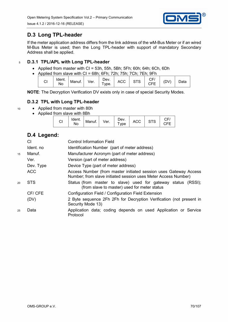
Open Metering System Specification Vol.2 – Primary Communication
Issue 4.1.2 / 2016-12-16 (RELEASE)
OMS-GROUP e.V. 70/107
D.3 Long TPL-header
If the meter application address differs from the link address of the wM-Bus Meter or if an wired M-Bus Meter is used; then the Long TPL-header with support of mandatory Secondary Address shall be applied.
D.3.1 TPL/APL with Long TPL-header 5
Applied from master with CI = 53h, 55h, 5Bh; 5Fh; 60h; 64h; 6Ch, 6Dh
Applied from slave with CI = 68h; 6Fh; 72h; 75h; 7Ch; 7Eh; 9Fh
CI Ident.
No Manuf. Ver.
Dev. Type.
ACC STS CF/ CFE
(DV) Data
NOTE: The Decryption Verification DV exists only in case of special Security Modes.
D.3.2 TPL with Long TPL-header
Applied from master with 80h 10
Applied from slave with 8Bh
CI Ident.
No Manuf. Ver.
Dev. Type
ACC STS CF/ CFE
D.4 Legend: CI Control Information Field
Ident. no Identification Number (part of meter address)
Manuf. Manufacturer Acronym (part of meter address) 15
Ver. Version (part of meter address)
Dev. Type Device Type (part of meter address)
ACC Access Number (from master initiated session uses Gateway Access Number; from slave initiated session uses Meter Access Number)
STS Status (from master to slave) used for gateway status (RSSI); 20
(from slave to master) used for meter status
CF/ CFE Configuration Field / Configuration Field Extension
(DV) 2 Byte sequence 2Fh 2Fh for Decryption Verification (not present in Security Mode 13)
Data Application data; coding depends on used Application or Service 25
Protocol

Open Metering System Specification Vol.2 – Primary Communication
Issue 4.1.2 / 2016-12-16 (RELEASE)
OMS-GROUP e.V. 71/107
Annex E (Normative): Communication profiles for compliance with national regulations
A national law may require additional demands on the security of meter communication. This annex lists the applicable communication profiles in order to comply with the national 5
regulation.
E.1 Requirements for Smart Meter Gateways in Germany
The German law requires an approval for the operation of a Smart Meter Gateway in Germany. This approval checks both the security and the interoperability of a Smart Meter Gateway. The [BSI TR03109] describes the requirement to such a Smart Meter Gateway. 10
Such a Smart Meter Gateway has to reject an unsecure communication link to a smart meter. The Annex E.1 describes which services and security methods of the OMS-Specification shall be applied and which services are not allowed to conform to [BSI TR03109].
Annex E may be subject to a more frequent update than this main document. Therefore, the 15
annex is not included. The current version (Release A or later) can be downloaded from the OMS Homepage (www.oms-group.org/en_downloads.html).

Open Metering System Specification Vol.2 – Primary Communication
Issue 4.1.2 / 2016-12-16 (RELEASE)
OMS-GROUP e.V. 72/107
Annex F (Normative): Transport Layer Security (TLS) with wM-Bus
The German law requires an approval for the operation of a Smart Meter Gateway in Germany. This approval checks both the security and the interoperability of a Smart Meter Gateway. The [BSI TR03109] describes the requirements to the interface of a Smart Meter Gateway. 5
One requirement is the TLS-protection of links to smart meters with a bidirectional communication interface in the Local Metrological Network (LMN). This Annex describes a BSI conform implementation of a TLS-communication on the wireless M-Bus.
TLS protected communication may also be used on wired M-Bus connections. However, the wired M-Bus interface is not a mandatory interface of a Smart Meter Gateway according to 10
[BSI TR03109].
Annex F may be subject to a more frequent update than this main document. Therefore, the annex is not included. The current version (Release A or later) can be downloaded from the OMS Homepage (www.oms-group.org/en_downloads.html).
15

Open Metering System Specification Vol.2 – Primary Communication
Issue 4.1.2 / 2016-12-16 (RELEASE)
OMS-GROUP e.V. 73/107
Annex G (Normative): Conversion of a Load Profile to single data points
G.1 Treatment of historical values in Compact Load Profiles with registers
Sets of historical billing values, indicated by the value group F (with F<255) of an OBIS-Code 5
and assigned to dedicated COSEM objects, are always coded with a final DIFE with the value 00h. The number of DIFEs is variable. Such sets of historical billing values shall use a Compact Load Profiles with registers.
The final DIFE shall be used in the DIBs of all three related data points (Base Time, Base Value and Compact Load Profile with registers). 10
NOTE: Sets of historical billing values, indicated by the value group F (with F=255) of an OBIS-Code, like a Due Date Value, never use the final DIFE and apply the Compact Load Profile without registers.
G.2 Exceptions
The Standard load profile and the Compact Load Profile shall be compatible to description of 15
[prEN 13757-3:2016].
NOTE: The compact profile with registers in [EN 13757-3:2013] was limited to max. two DIFE's. This limitation does not apply for OMS-meters.
G.3 Data set of the Example
The following examples show how an original set of periodical consumption values is coded 20
as Standard Load Profile or Compact Load Profile and how these Load Profiles are converted to a set of single M-Bus data points.
Table G1– Example: Load profile of consumption values for a water meter
1st value at the end of the month 2008-01-31 65 litres (10-3 m3)
2nd value at the end of the month 2008-02-29 209 litres
3rd value at the end of the month 2008-03-31 423 litres
4th value at the end of the month 2008-04-30 755 litres
Last value at the end of the month 2008-05-31 1013 litres
25

Open Metering System Specification Vol.2 – Primary Communication
Issue 4.1.2 / 2016-12-16 (RELEASE)
OMS-GROUP e.V. 74/107
G.4 Example for Standard Load Profile
Table G2 – Example: Standard Load Profile composed of the periodical volume values
DIB VIB Data Hex coded
(LSByte first) Data field Storage number
2 digit BCD 8 Size of storage block 5 89 04 FD 22 05
2 digit BCD 8 Storage interval in months 1 89 04 FD 28 01
16 bit binary 12 Date (Type G) 2008-05-31 82 06 6C 1F 15
8 digit BCD 8 Volume (liters) 65 8C 04 13 65 00 00 00
8 digit BCD 9 Volume (liters) 209 CC 04 13 09 02 00 00
8 digit BCD 10 Volume (liters) 423 8C 05 13 23 04 00 00
8 digit BCD 11 Volume (liters) 755 CC 05 13 55 07 00 00
8 digit BCD 12 Volume (liters) 1013 8C 06 13 13 10 00 00
Table G3 – Example: Periodical volume values converted to single data points
DIB VIB Data Hex coded
(LSByte first) Data field Storage number
16 bit binary 8 Date (Type G) 2008-01-31 82 04 6C 1F 11
8 digit BCD 8 Volume (liters) 65 8C 04 13 65 00 00 00
16 bit binary 9 Date (Type G) 2008-02-29 C2 04 6C 1D 12
8 digit BCD 9 Volume (liters) 209 CC 04 13 09 02 00 00
16 bit binary 10 Date (Type G) 2008-03-31 82 05 6C 1F 13
8 digit BCD 10 Volume (liters) 423 8C 05 13 23 04 00 00
16 bit binary 11 Date (Type G) 2008-04-30 C2 05 6C 1E 14
8 digit BCD 11 Volume (liters) 755 CC 05 13 55 07 00 00
16 bit binary 12 Date (Type G) 2008-05-31 82 06 6C 1F 15
8 digit BCD 12 Volume (liters) 1013 8C 06 13 13 10 00 00
NOTE: Corresponding table cells in Tables G2 and G3 are marked with corresponding 5
background colours.

Open Metering System Specification Vol.2 – Primary Communication
Issue 4.1.2 / 2016-12-16 (RELEASE)
OMS-GROUP e.V. 75/107
G.5 Example for Compact Load Profile
Table G4 – Example: Compact Load Profile composed of the periodical volume values
DIB VIB Data Hex coded
LS Byte first
Sto
rag
e n
um
ber
LV
AR
Spacing control byte
Sp
acin
g v
alu
e
byte
Data
Data
fie
ld
Incre
men
t
mo
de
Sp
acin
g u
nit
Data
fie
ld
8 digit BCD
8 Volume (liters)
- - - - - 65 8C 04 13 65 00
00 00
16 bit binary
8 Format G - - - - - 2008-01-31 82 04 6C 1F 11
Variable length
8 Volume (liters)
10 Incre-ments
Full month
4 digit BCD
254 144, 214, 332, 258
8D 04 93 1F 0A
7A FE 44 01 14
02 32 03 58 02
Table G5 – Example: Periodical volume values converted to single data points
DIB VIB data Hex coded
(LSByte first) Data field Storage number
16 bit binary
8 Format G 2008-01-31
82 04 6C 1F 11
16 bit binary
9 Format G 2008-02-29
C2 04 6C 1D 12
16 bit binary
10 Format G 2008-03-31
82 05 6C 1F 13
16 bit binary
11 Format G 2008-04-30
C2 05 6C 1E 14
16 bit binary
12 Format G 2008-05-31
82 06 6C 1F 15
8 digit BCD
8 Volume (liters) 65 8C 04 13 65 00 00 00
8 digit BCD
9 Volume (liters) 209 CC 04 13 09 02 00 00
8 digit BCD
10 Volume (liters) 423 8C 05 13 23 04 00 00
8 digit BCD
11 Volume (liters) 755 CC 05 13 55 07 00 00
8 digit BCD
12 Volume (liters) 1013 8C 06 13 13 10 00 00
NOTE: Corresponding table cells in Tables G4 and G5 are marked with corresponding 5
background colours.

Open Metering System Specification Vol.2 – Primary Communication
Issue 4.1.2 / 2016-12-16 (RELEASE)
OMS-GROUP e.V. 76/107
Annex H (Informative): Gas Meter Consumption Data and their Coding
H.1 Glossary
Table H1 – Glossary of the Gas meter consumption data
Vm The volume at measurement conditions
Vtc Temperature converted volume
Vb The volume at base conditions
Measurement conditions Conditions of the gas whose volume is measured at the point of measurement (e.g. the temperature and the pressure of the gas) EN 12405:2002 3.1.2
Base conditions Fixed conditions used to express the volume of gas independently of the measurement conditions EN 12405:2002 3.1.3
Converted volume The converted volume from the quantity measured at metering conditions into a quantity at base conditions
H.2 Overview 5
For billing purposes the measured volume of a gas meter needs to be converted into energy. Depending on the technology of the gas meter there might be several parameters for this conversion:
Temperature
Pressure 10
Gas calorific value
The conversion from the volume at measurement conditions (Vm) to the volume at base conditions (Vb) can be done by the gas meter, by a conversion device and/or by the billing system. Gas meter with build in temperature conversion device convert Vm to Vtc.
In general mentioned conversions can be done explicitly using devices measuring the specific 15
condition or also implicitly by meters that measure independently from the specific condition.
To inform the billing centre on possible conversions already done by the meter or a conversion device, the consumption data transmitted shall include a clear indication on both the conversion types and the base conditions to which the conversion is done. For meters with integrated or external conversion directly to energy the energy-oriented VIFs (e.g. “kWh”) to-20
gether with the Device Type “gas” = 03h will provide such a clear indication which does not require further information.

Open Metering System Specification Vol.2 – Primary Communication
Issue 4.1.2 / 2016-12-16 (RELEASE)
OMS-GROUP e.V. 77/107
H.3 Volume at Measurement Conditions
All conversions are done solely at the billing centre, by assumption of measurement conditions that could not be measured, typically using legally defined gas temperatures and typical gas installations and/or installation height to take the pressure into account.
Figure 20 – Gas meter providing volume at measurment conditions 5
Gas meter
Vm
Note that the same coding is used for the raw, uncorrected original value if the meter internally corrects its volume accumulation for possible flow dependent errors since this will not influence the billing process.
Suitable OBIS and M-Bus codes can be found in Annex A. 10
H.4 Temperature Converted Volume Vtc
An individual meter based volume conversion to Vtc (in contrast to the “global” billing centre based conversion) can be achieved either mechanically or electronically. It can be implemen-ted either internally in the meter or by some external conversion device which then transmits converted values to the billing centre. Note that such a temperature conversion is based on a 15
base temperature, which must be known to the billing centre. The default value for such a temperature at base conditions is 15 °C according to the [EN 1359:1998 + A1:2006].
If a meter uses a different base temperature its temperature at base conditions information shall be transmitted with each volume data message.
Note that meter data can be converted by the billing centre to its “billing temperature at base 20
conditions” if this is different either from the default temperature of 15 °C or from the meters transmitted temperature at base conditions.
Figure 21 – Gas meter providing temperature converted volume
Gas meter
Vtc
T
Suitable OBIS and M-Bus codes can be found in Annex A. 25

Open Metering System Specification Vol.2 – Primary Communication
Issue 4.1.2 / 2016-12-16 (RELEASE)
OMS-GROUP e.V. 78/107
H.5 Temperature and Pressure Converted Volume
In addition to a volume conversion just regarding temperature an individual meter might convert its measured volume to base conditions regarding temperature and pressure. To comply with standard conditions, which are usually stated by national regulations and to allow the creation of gas bills that can easily be understood by the consumer, the same temperature 5
at base conditions shall be used as for the calorific value in the case when both temperature and pressure are converted.
Devices complying with this do not need to send the information of the temperature at base conditions.
Note that a purely pressure converted volume, without temperature, is not supported. 10
Such a volume conversion is based on a pressure at base conditions, which must be known to the billing centre. The default value for such a pressure at base conditions is 1013,25 mbar. If a meter uses a different value for pressure at base conditions such pressure at base conditions information shall be added to each volume data message.
Note that meter data can be converted at the billing centre to its “billing pressure at base 15
conditions” if this is different either from the default pressure of 1013,25 mbar or from the meter’s transmitted pressure at base conditions.
Figure 22 – Gas meter providing providing temperature and pressure converted volume
Gas meter
Vm
temperature and
preasure
converted
T
Vb
p
Suitable OBIS and M-Bus codes can be found in Annex A and Annex B. 20

Open Metering System Specification Vol.2 – Primary Communication
Issue 4.1.2 / 2016-12-16 (RELEASE)
OMS-GROUP e.V. 79/107
H.6 OBIS / COSEM Application of Physical Units for Gas
(Extract from [DLMS UA] Blue Book ed. 11)
Table H2 shows available physical units for the gas data objects given above. By application of a scale factor (ref. Table H3) the values can be scaled as required.
Table H2 – Enumerated values for physical units 5
Unit ::= enum
Unit Quantity Unit name SI definition
(comment)
(9) °C temperature (T) degree-celsius K – 273,15
(13) m3 volume (V)
rV , meter constant or pulse value (volume)
cubic meter m3
(14) m3 Converted volume cubic meter m3
(19) l Volume litre 10-3 m3
(23) Pa pressure (p) pascal N/m2
(24) bar pressure (p) bar 105 N/m2
(52) K temperature (T) kelvin
Some examples are shown in Table H3 below.
Table H3 – Examples for scaler-unit
Value Scaler Unit Data
263788 -3 m3 263,788 m3
593 3 Wh 593 kWh
3467 0 V 3467 V

Open Metering System Specification Vol.2 – Primary Communication
Issue 4.1.2 / 2016-12-16 (RELEASE)
OMS-GROUP e.V. 80/107
Annex I (Normative): Collision Avoiding Mechanism of the gateway
The following describes a mechanism for automatic retransmissions of interrogating devices in order to resolve collisions on the radio channel. The algorithm is based on a maximum number of N retries and choosing a random listen-after-talk-timeslot of the addressed meter. 5
Furthermore it evaluates the received message types to prevent disturbing other conversations.

Open Metering System Specification Vol.2 – Primary Communication
Issue 4.1.2 / 2016-12-16 (RELEASE)
OMS-GROUP e.V. 81/107
I.1 Flowchart
Figure I1 - Collision avoiding algorithm
n = 1
T = Random
T is equally distributed
between 1 and 2
Wait until datagram from target-meter
received
t = T ?
Transmit datagram to target-meter
t = t + 1
n < 2or
t > 2?
n = n + 1
n > N ?
no
no
yes
no
yes
End: Communication
failed
yes
Start
N: Maximum Number of retries
t = 1
ACK or RSP-UD received?
Addresse of ACK or RSP ?
yes
no
yes
no
no
Furtherdatagram pending?
yes
End: Communication
OK
Transmit datagram to target-meter
(optional)
Timeout?
yes
n > 2?
T = 1
no
yes
Re-init algorithmn =1t = 1
(T = 1)
no

Open Metering System Specification Vol.2 – Primary Communication
Issue 4.1.2 / 2016-12-16 (RELEASE)
OMS-GROUP e.V. 82/107
I.2 Explanation
The flowchart shows the procedure to transmit a message to a bidirectional meter including the retry-mechanism. The parameter N gives the maximum number of retries.
The retry-algorithm applies three variables:
n Counts the number of tries to send the command 5
t Counts the number of datagrams received during the actual try
T Determines the datagram which will be followed by a transmission
In case of two unsuccessful tries resulting in n larger than 2, T is randomly chosen to 1 or 2 with a uniform distribution at the start of every (re-)try.
The basic idea is that within every try the interrogating device uses only one of two 10
opportunities to transmit. This means that for both the first and second try the very first opportunity is used and for all following tries it would be either the first or the second one. The unused opportunity reduces the jamming-probability for competing devices and therefore contributes to a recovery of the overall-system.
A transmission to the addressed module is only performed under certain conditions. Of course, 15
the general condition is the reception of a datagram from the target meter to meet the following listen-after-talk window. The algorithm evaluates furthermore, if the datagram is related to an already ongoing conversation, which is the case if the datagram is an acknowledgment or a response. In this case, it is further evaluated if this datagram is addressed to the interrogating device trying to send a transmission. If not, the device keeps on listening in order to leave this 20
other conversation undisturbed. In case the ACK or RSP is dedicated to the device, the previous transmission is considered as successfully transmitted8.
If the received datagram is neither part of another conversation nor the confirmation that a previous datagram was received, this would be an opportunity to send the datagram in case t equals T. Again, this latter additional condition resolves collision-scenarios with several 25
devices transmitting simultaneously.
I.3 Example: Access of one gateway without collision
Assume a scenario with only one gateway addressing a meter with a sufficient radio propagation in-between. The algorithm is initialized with n = 1, t = 1 and T = 1. As a consequence, the very first received datagram from the target meter is followed by the 30
gateways transmission. An ACK by the meter, which should be received in a collision-free environment, confirms the reception and resulting in the transmission of the next datagram by the gateway. Therefore, compared to a system without the retry-mechanism, the performance in terms of latency or throughput is not influenced in any way.
The following flowchart shows this behaviour versus time together with the three variables of 35
the algorithm.
8 Based on the assumption, that the access-counter of the response can be used to match the answer
of the interrogated module to the query.

Open Metering System Specification Vol.2 – Primary Communication
Issue 4.1.2 / 2016-12-16 (RELEASE)
OMS-GROUP e.V. 83/107
Figure I2 – Timing diagram without collisions
GW
(LLA=GW1)
Meter
(LLA=ALA=MTR)
RF-Connection with Command
After meter transmitts and t = T, GW sends Command.
Message is received during a short reception windows followed after every transmission (when bit B=1 and A=0) An Acknowledge is responded with predefined delay.
GW receive Acknowledge and finish communikation. Because this is a new telegram, the algorithm is re-initialized.
Meter receive „End of Transmission“ and stops retransmission.
GW has new CMD. Algorithm is initialized.
n t T
1 1 1
1 1 1
I.4 Example: Access of two gateways with collision
Assume a scenario with two gateways and a meter, again with sufficient and equal radio propagation between the gateways and the meter. Due to some reason, on both gateways a 5
command appears to be sent to the meter. Note that it cannot be sent immediately in case the meter's receiver is not always on. Therefore this scenario applies even in case of minutes between the appearances of the commands if the addressed meter has not transmitted since then, meaning that there was no opportunity to transmit the command.
Both gateways initialize the algorithm in the same way. In our assumption the received field 10
strength of both gateways is equal at the meter and therefore the transmissions are jammed. Because the meter cannot receive any command in this case, there will not be an ACK by the module. Therefore the number of received datagrams during this first try is increased to 2. This furthermore results in starting the next try by increasing n from 1 to 2. Also for the second try, T is set to 1 (see flow chart) and therefore the very next opportunity is used, which again ends 15
up in a collision. For the next try with n = 3, the random generator of every gateway determines T which now can be 1 or 2. Assuming a uniform distribution, there is a 50 % probability that two gateways choose different timeslots. This scenario is sketched in the following chart.

Open Metering System Specification Vol.2 – Primary Communication
Issue 4.1.2 / 2016-12-16 (RELEASE)
OMS-GROUP e.V. 84/107
Figure I3 – Timing diagram with collisions
GW1
(LLA=GW1)
Meter
(LLA=ALA=MTR)
RF-Connection with Command
After meter transmitts
and t = T, GW1
sends Command.
SND-NR (C=44;MTR)
CI=7A;ACC=51
SND-UD (C=73;GW1)
CI=5B;MTR;ACC=11
ACK (C=00;MTR)
CI=8A;ACC=11
SND-NKE (C=40;GW1)
CI=80;MTR;ACC=12
GW1 receives
acknowledge and
finishes communikation.
Because this is a new
telegram, the algorithm
is re-initialized.
GW1 has new CMD.
Algorithm is
initialized.
n t T
1 1 1
2 1 1
GW2
(LLA=GW2)n t T
1 1 1
3 1 2
After meter transmitts
and t = T, GW2
sends Command.
GW2 has new CMD.
Algorithm is
initialized.SND-NR (C=44;MTR)
CI=7A;ACC=51
SND-UD (C=73;GW2)
CI=5B;MTR;ACC=22
Collision, meter does
not receive any CMD,
therefore, it does not
ACK
SND-NR (C=44;MTR)
CI=7A;ACC=53
SND-NR (C=44;MTR)
CI=7A;ACC=53
GW1 starts 3rd try.
Random generator picks
1st opportunity (T = 1).
GW2 starts 3rd try.
Random generator picks
2nd opportunity (T = 2).
After meter transmitts
and t = T, GW1 sends
Command.
SND-UD (C=73;GW1)
CI=5B;MTR;ACC=11
Although meter transmits,
GW2 does not send
command because t ≠ T.
Afterwards, t is in creased
3 2 2
ACK (C=00;MTR)
CI=8A;ACC=11
Although meter transmits
and t = T, GW2 does not
send command because
ACK use a wrong ACC-
Number.
SND-NR (C=44;MTR)
CI=7A;ACC=54
SND-NR (C=44;MTR)
CI=7A;ACC=54
SND-UD (C=73;GW2)
CI=5B;MTR;ACC=22
After meter transmits
again and t = T, GW2
sends Command.3 2 2
ACK (C=00;MTR)
CI=8A;ACC=22
SND-NKE (C=40;GW2)
CI=80;MTR;ACC=23
ACK (C=00;MTR)
CI=8A;ACC=22GW2 receives
acknowledge and finishes
communikation. Because
this is a new telegram, the
algorithm is re-initialized.
1 1 1
3 2 2
3 2 2
SND-NR (C=44;MTR)
CI=7A;ACC=52
SND-NR (C=44;MTR)
CI=7A;ACC=52
GW1 starts 2nd try. GW2 starts 2nd try.
After meter transmitts
and t = T, GW1 sends
Command.
SND-UD (C=73;GW1)
CI=5B;MTR;ACC=11
2 1 1
After meter transmitts
and t = T, GW2
sends Command.
SND-UD (C=73;GW2)
CI=5B;MTR;ACC=22
Collision, meter does
not receive any CMD,
therefore, it does not
ACK
3 1 1
1 1 1
tTxd
tTxd
After the collision of the gateways first transmission, both start a 3rd try with GW1 choosing the 1st and GW2 the 2nd opportunity. As a result, GW1 transmits the command after the next 5
received datagram, whereas GW2 waits for the next possibility. Because the following transmissions of the meter are dedicated to GW1, GW2 does not take these opportunities, although t is equivalent to T. Note that the received datagrams dedicated to another conversation do not result in incrementing t (see the flowchart of the algorithm). After this conversation with GW1 is finished, GW2 takes the next datagram originating from the meter 10
to transmit its pending datagram.

Open Metering System Specification Vol.2 – Primary Communication
Issue 4.1.2 / 2016-12-16 (RELEASE)
OMS-GROUP e.V. 85/107
I.5 Collision Probabilities
If more than one interrogating device wants to send a command at the same time, this results always in a collision during the first try. If there are two devices, the probability to get a collision during the nth try with n larger than 2 is 0,5² × 2 = 0,5.
0,5² is the probability that both devices choose the same opportunity and the multiplier 2 is 5
reasoned by two possible opportunities. In general, the probability for collision is 1 in case of the first and second try and 0,5 for every other retries in case of two competing devices.
With the number of tries, the probability decreases that further tries are necessary. For example, the probability to have at least 3 tries is 1 and is the consequence of the 100 % collision probability for the 1st and 2nd try. The probability to have at least 4 tries is 1 × 1 × 0,5 10
and therefore the result of having a collision in the 1st, 2nd and 3rd try. In general, the probability to have the necessity for at least n tries is 1 × 0,5n-2 (for n > 2).
Figure I4 – Collision probability
The probability for 12 tries or more is about 0,2 %, therefore a maximum number of N = 11 15
would be a suited limit for the proposed algorithm. This limits the number of opportunities to a maximum of 1 + 1 + 9 × 2 = 20.
Retries for two devices
0
0.1
0.2
0.3
0.4
0.5
0.6
0.7
0.8
0.9
1
1 2 3 4 5 6 7 8 9 10 11 12 13 14 15
Number of tries
Pro
bab
ilit
y
Probability of (re-)tries

Open Metering System Specification Vol.2 – Primary Communication
Issue 4.1.2 / 2016-12-16 (RELEASE)
OMS-GROUP e.V. 86/107
Annex J (Informative): Handling of Message Counter
Figure J1 – Example of Message counter handling
5

Open Metering System Specification Vol.2 – Primary Communication
Issue 4.1.2 / 2016-12-16 (RELEASE)
OMS-GROUP e.V. 87/107

Open Metering System Specification Vol.2 – Primary Communication
Issue 4.1.2 / 2016-12-16 (RELEASE)
OMS-GROUP e.V. 88/107

Open Metering System Specification Vol.2 – Primary Communication
Issue 4.1.2 / 2016-12-16 (RELEASE)
OMS-GROUP e.V. 89/107

Open Metering System Specification Vol.2 – Primary Communication
Issue 4.1.2 / 2016-12-16 (RELEASE)
OMS-GROUP e.V. 90/107
Annex K (Normative): Descriptors
K.1 General
The purpose of a descriptor is the declaration of the meaning of DIB-elements in the individual device. Following DIB-elements of data points can be declared by descriptors.
Table K1 – Overview of descriptors and related DIB-elements 5
DIB-element Descriptor
Storage number Storage interval descriptor
Tariff Tariff descriptor
Subunit Subunit descriptor
The link between the descriptor and the data point(s) is always the DIB-element. The DIB-element of a data point is identical to the DIB-element of the descriptor (see Table K1). The values of the other DIB elements do not matter. For example, the subunit descriptor with a subunit of 1 is applicable for all data points with the same subunit regardless of its value of the DIB-elements storage number, tariff or function. 10
A descriptor is valid for the whole device; e. g. the declaration of tariff number 1 shall be applied to all storage numbers and subunits.
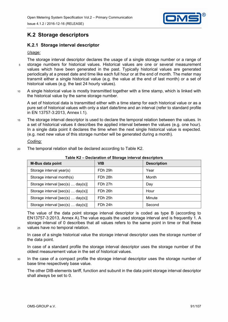
Open Metering System Specification Vol.2 – Primary Communication
Issue 4.1.2 / 2016-12-16 (RELEASE)
OMS-GROUP e.V. 91/107
K.2 Storage descriptors
K.2.1 Storage interval descriptor
Usage:
The storage interval descriptor declares the usage of a single storage number or a range of storage numbers for historical values. Historical values are one or several measurement 5
values which have been generated in the past. Typically historical values are generated periodically at a preset date and time like each full hour or at the end of month. The meter may transmit either a single historical value (e.g. the value at the end of last month) or a set of historical values (e.g. the last 24 hourly values).
A single historical value is mostly transmitted together with a time stamp, which is linked with 10
the historical value by the same storage number.
A set of historical data is transmitted either with a time stamp for each historical value or as a pure set of historical values with only a start date/time and an interval (refer to standard profile in EN 13757-3:2013, Annex I.1).
The storage interval descriptor is used to declare the temporal relation between the values. In 15
a set of historical values it describes the applied interval between the values (e.g. one hour). In a single data point it declares the time when the next single historical value is expected. (e.g. next new value of this storage number will be generated during a month).
Coding:
The temporal relation shall be declared according to Table K2. 20
Table K2 – Declaration of Storage interval descriptors
M-Bus data point VIB Description
Storage interval year(s) FDh 29h Year
Storage interval month(s) FDh 28h Month
Storage interval [sec(s) … day(s)] FDh 27h Day
Storage interval [sec(s) … day(s)] FDh 26h Hour
Storage interval [sec(s) … day(s)] FDh 25h Minute
Storage interval [sec(s) … day(s)] FDh 24h Second
The value of the data point storage interval descriptor is coded as type B (according to EN13757-3:2013, Annex A).The value equals the used storage interval and is frequently 1. A storage interval of 0 describes that all values refers to the same point in time or that these values have no temporal relation. 25
In case of a single historical value the storage interval descriptor uses the storage number of the data point.
In case of a standard profile the storage interval descriptor uses the storage number of the oldest measurement value in the set of historical values.
In the case of a compact profile the storage interval descriptor uses the storage number of 30
base time respectively base value.
The other DIB-elements tariff, function and subunit in the data point storage interval descriptor shall always be set to 0.

Open Metering System Specification Vol.2 – Primary Communication
Issue 4.1.2 / 2016-12-16 (RELEASE)
OMS-GROUP e.V. 92/107
Scope of application:
The storage interval descriptor is mandatory for all historical values, except for
• Historical values providing a time stamp for each used storage number,
• Storage numbers, using a final DIFE (assignment is done by register-ID),
• Transmissions with compact profile according to OMSS-Vol2. Annex G (Note that any 5
compact profile can be converted to a set of historical values with timestamps).
Storage number 0 (without final DIFE) is exclusively being used for current values and values without a temporal relation, e. g. the fabrication number. It is not permitted to use the storage interval descriptor for storage number 0.
Storage number 1 (without final DIFE) is being used for due date values. As long as the due 10
date is provided no storage interval descriptor is required.
K.2.2 Storage range descriptor
Table K3 – Declaration of Storage range descriptors
M-Bus data point VIB Description
First storage number for cyclic storage
FDh 20h Time point for start of range (oldest value)
Last storage number for cyclic storage
FDh 21h Time point for end of range (newest value)
Size of storage block FDh 22h Number of applied storage numbers
The storage range descriptor FDh 21h uses the storage number of newest value in the load profile. The storage range descriptors FDh 20h and FDh 22h are using the storage number of 15
the oldest value in the load profile. The data point sub fields for tariff, function and subunit in the data point storage range descriptor shall be set to 0. The storage range descriptors FDh 20h and FDh 21h are not transmitting values.
The transmission of storage range descriptors is generally optional, with a few exceptions.
Under the following conditions the use of the storage range descriptor is mandatory: 20
1. If several sets of historical values with more than one pair of values is transmitted a
storage range descriptor according to Table K3 shall be included in the message. All
sets in this message shall use the same type of storage range descriptor.
2. If the storage number of the oldest value in a set of historical values is not the
smallest storage number in this set then this storage number shall be declared with 25
the storage range descriptor FDh 20h.

Open Metering System Specification Vol.2 – Primary Communication
Issue 4.1.2 / 2016-12-16 (RELEASE)
OMS-GROUP e.V. 93/107
K.3 Subunit descriptor
The subunit descriptor declares the usage of the subunit number.
The subunit descriptor is coded with 01h FDh 23h xx. The values for xx are listed in Table K4.
NOTE: The VIB of the subunit descriptor is the same as for the tariff descriptor.
Table K4 – Subunit index values for the subunit descriptor 5
Index value
Description Media type Comment
0 Main register, legacy all
1 OBIS value group B=1 electricity meter
2 OBIS value group B=2 electricity meter
3 OBIS value group B=3 electricity meter
4 OBIS value group B=4 electricity meter
5 Tariff subunit all
6 Minimum subunit all
7 Maximum subunit all
8 Data logger all
9 Event logger all E. g. error logging
10 Test subunit/test mode all Test results
11 Calibration subunit all Calibration results
12 Adjustment subunit all Adjustment values
13..20 Pulse collector 1…8 all
21…29 Configuration subunit/configuration mode
all
30…99 Reserved
100…127 Manufacturer specific all
128…255 Reserved for other descriptors
It is not permitted to use the subunit descriptor for the subunit value 0. The transmission of the subunit descriptors is mandatory for all subunit values greater than 0. For the case of a Subunit index value = 0 the transmission of the subunit descriptors may be omitted.
The subunit descriptor shall use the subunit number of the declared subunit. The DIB-elements storage number, function and tariff in the data point 'subunit descriptor' shall be set to 0. 10

Open Metering System Specification Vol.2 – Primary Communication
Issue 4.1.2 / 2016-12-16 (RELEASE)
OMS-GROUP e.V. 94/107
K.4 Tariff descriptor
The tariff descriptor declares the usage of the tariff register number.
The tariff descriptor is coded with 01h FDh 23h xx. The values for xx are listed in Table K5.
NOTE: The VIB of the tariff descriptor is the same as for the subunit descriptor.
Table K5 – Tariff index values for the tariff descriptor 5
Index value
Description Device type Comment
0…127 Reserved for other descriptors
128…139 Manufacturer specific
140…149 Reserved
Time based tariffs
150 Absolute time of day All E.g. 8:00 to 11:00 each day
151 Weekdays All e.g. each Saturday and Sunday
152 Days in Month All e.g. each 15.
153…159 Reserved
Threshold based tariffs
160 Difference Temperature Heat, Cold
161 Forward temperature Heat, Cold,
162 Return temperature Heat, Cold
163 Return temperature threshold for calculation of theoretical energy
Heat, Cold a
164 Volume Flow Water, Heat, Cold, Gas
165 Power Electricity, Heat, Cold
166…189 Reserved
Consumption based tariffs
190 Energy consumption Electricity, Heat, Cold
e.g. after consumption of 100 kWh
191 Volume consumption Water, Heat, Cold, Gas
192 Financial consumption All e.g. prepaid tariffs
193…209 Reserved
Combined tariffs
210 Time and threshold based
211 Time and consumption based
212 Threshold and consumption based
213…229 Reserved

Open Metering System Specification Vol.2 – Primary Communication
Issue 4.1.2 / 2016-12-16 (RELEASE)
OMS-GROUP e.V. 95/107
Table K5 (continued)
Index value
Description Device type Comment
Other tariffs
230 Energy positive Electricity, Heat, Cold
231 Energy negative Electricity, Heat, Cold
232 Energy heating Heat, Cold,
233 Energy cooling Heat, Cold,
234 External input 1 All Controlled by user from outside
235 External input 2 All
236…249 Reserved
250…255 Reserved for table extension
a The energy is accumulated in tariff registers depending on the return (outlet) temperature. The quantity of this energy results from a mathematical calculation based on the difference of return (outlet) temperature and a pre-defined return temperature threshold. It can be distinguished between accumulated energy in case of return temperature is lower or higher than the return threshold value. This can be signaled with the orthogonal VIFE 40h or 48h.
It is not permitted to use the tariff descriptor for the tariff value 0. The transmission of tariff descriptors is mandatory for all tariff values greater than 0, except for the following conditions:
A combined heat/cooling meter uses the tariff register 1 for the cooling energy. 5
The tariff descriptor shall use the tariff register number of the declared tariff. The DIB-elements storage number, function and subunit in the data point 'tariff descriptor' shall be set to 0.

Open Metering System Specification Vol.2 – Primary Communication
Issue 4.1.2 / 2016-12-16 (RELEASE)
OMS-GROUP e.V. 96/107
K.5 Examples
K.5.1 Example: Storage descriptor
Table K6 – Example load profile for storage descriptor
1st value at the end of the month 2008-01-31 65 litres (10-3 m3)
2nd value at the end of the month 2008-02-29 209 litres
3rd value at the end of the month 2008-03-31 423 litres
4th value at the end of the month 2008-04-30 755 litres
Last value at the end of the month 2008-05-31 1013 litres
Table K7 – Example for coding of the storage descriptor 5
DIB VIB Data Hex coded
(LSByte first) Data field Storage number
2 digit BCD
8 Size of storage block 5 89 04 FD 22 05
2 digit BCD
8 Storage Interval Descriptor months
1 89 04 FD 28 01
16 bit binary
12 Date (Type G) 2008-05-31
82 06 6C 1F 15
8 digit BCD
8 Volume (liters) 65 8C 04 13 65 00 00 00
8 digit BCD
9 Volume (liters) 209 CC 04 13 09 02 00 00
8 digit BCD
10 Volume (liters) 423 8C 05 13 23 04 00 00
8 digit BCD
11 Volume (liters) 755 CC 05 13 55 07 00 00
8 digit BCD
12 Volume (liters) 1013 8C 06 13 13 10 00 00
0 bit 12 Storage Range Descriptor “End”
- 80 06 FD 21
K.5.2 Example: Subunit descriptor
Example for a subunit descriptor for subunit 2: 81h 80h 40h FDh 23h 08h
K.5.3 Example: Tariff descriptor
Example for a tariff descriptor for tariff 3: 81h 30h FDh 23h 82h 10

Open Metering System Specification Vol.2 – Primary Communication
Issue 4.1.2 / 2016-12-16 (RELEASE)
OMS-GROUP e.V. 97/107
Annex L (Normative): Timing Diagram
The next pages show examples of Timing diagrams. These are mainly examples of the S- and T-Mode. Examples of C-Mode are similar but differ slightly in the timing (refer to Annex E of [EN 13757-4:2013]). If the Access number not explicit declared then the shown Access number is the Access Number of the ELL or of the TPL (if the ELL not exists). 5
L.1 Legend
GW
(LLA=GW)Meter (LLA=RFA
ALA=MTR)LLA=Link Layer AddressALA= Application Layer AddressIn this example the LLA is the Address from the RF-adapter „RFA“ and the Meter Application address is „MTR“
The GW receives continuously!
The reception window of the Meter closes after tRO(Max),e.g. 3 milliseconds for T-Mode.
The continuous line means the message was successful received.
The GW with address „GW“ sends a message of type „Send User Data“ (C-Field=53h) to the Meter with address „MTR“ and uses an Access Number „1“.
The dashed line means the message was transmitted but not received. The reception window
of the Meter opens after tRO(Min), e.g. 2 milli-seconds for T-Mode.
A delay of tTxD seconds
A dotted reference line indicates a synchronous event for both trans-mitter and receiver, e.g. the start of the time-out for reception windows, i.e. when the trans-mission was finished.
Time gap
The GW has to send the response within tRO (between 2nd and 3rd millisecond for T-Mode).
tRO(Max)
tRO(Max)
tRO(Min)
10

Open Metering System Specification Vol.2 – Primary Communication
Issue 4.1.2 / 2016-12-16 (RELEASE)
OMS-GROUP e.V. 98/107
L.2 Unidirectional meter with synchronous and asynchronous transmission
GW
(LLA=GW)
Meter
(LLA=ALA=MTR)
Synchronous message
The individual synchronous transmission interval
Synchronous message with new data; increase ELL-ACC by 1increase TPL-ACC by 1
asynchronous message with new data; stay with ELL-ACCincrease TPL-ACC by 1
asynchronous message with new data; stay with ELL-ACCincrease TPL-ACC by 1
asynchronous message with old data; stay with ELL-ACCstay with TPL-ACC
asynchronous message with new data; stay with ELL-ACCincrease TPL-ACC by 1
Synchronous message with old data; increase ELL-ACC by 1 stay with TPL-ACC
asynchronous message with new data; stay with ELL-ACCincrease TPL-ACC by 1
5
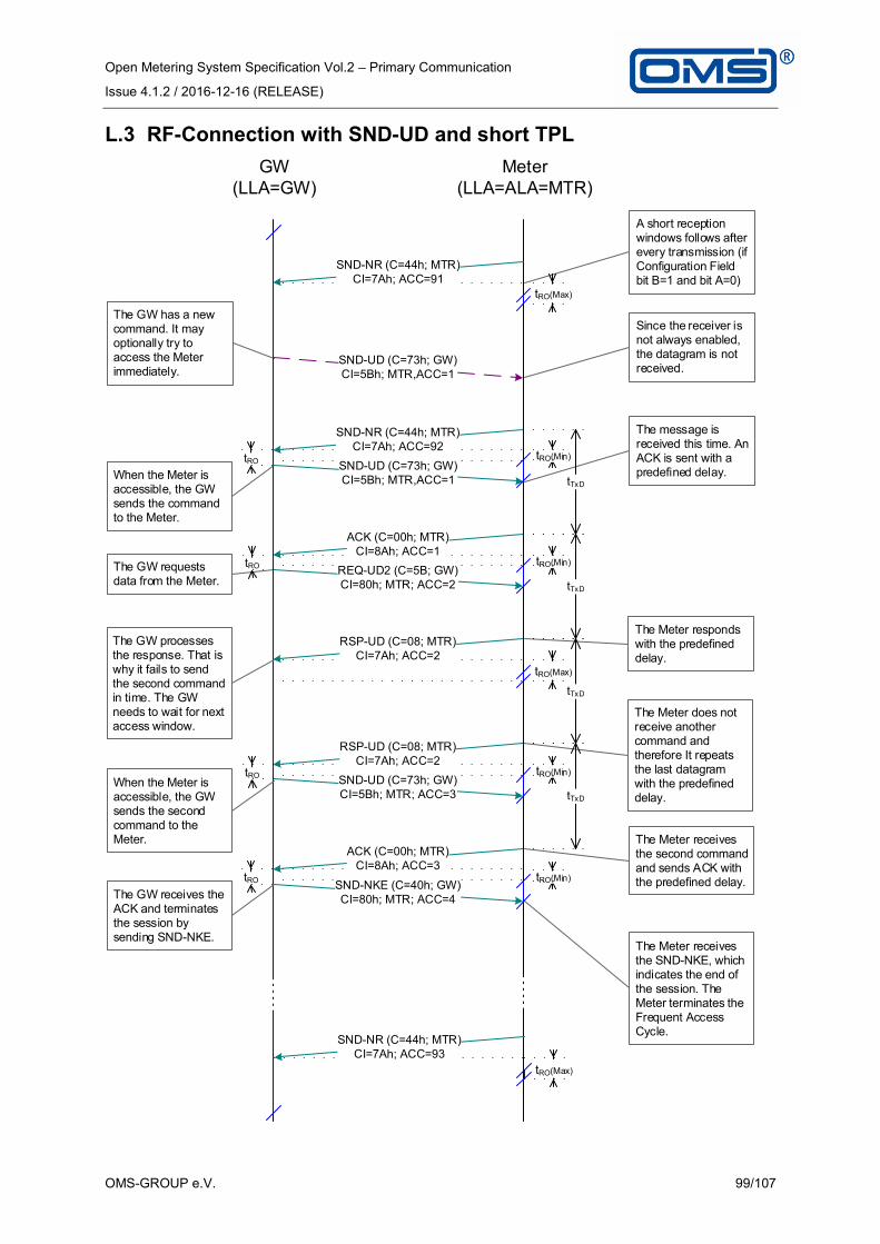
Open Metering System Specification Vol.2 – Primary Communication
Issue 4.1.2 / 2016-12-16 (RELEASE)
OMS-GROUP e.V. 99/107
L.3 RF-Connection with SND-UD and short TPL
GW
(LLA=GW)
Meter
(LLA=ALA=MTR)
The GW requests data from the Meter.
When the Meter is accessible, the GW sends the command to the Meter.
A short reception windows follows after every transmission (if Configuration Field bit B=1 and bit A=0)
The GW has a new command. It may optionally try to access the Meter immediately.
Since the receiver is not always enabled, the datagram is not received.
The message is received this time. An ACK is sent with a predefined delay.
tRO(Max)
The Meter responds with the predefined delay.
The GW processes the response. That is why it fails to send the second command in time. The GW needs to wait for next access window.
The Meter does not receive another command and therefore It repeats the last datagram with the predefined delay.
When the Meter is accessible, the GW sends the second command to the Meter.
The GW receives the ACK and terminates the session by sending SND-NKE.
The Meter receives the second command and sends ACK with the predefined delay.
The Meter receives the SND-NKE, which indicates the end of the session. The Meter terminates the Frequent Access Cycle.
tRO(Min)
tRO(Max)
tRO(Min)
tRO(Min)
tRO(Min)
tRO(Max)

Open Metering System Specification Vol.2 – Primary Communication
Issue 4.1.2 / 2016-12-16 (RELEASE)
OMS-GROUP e.V. 100/107
L.4 Transmission of fragmented message with SND-UD
GW
(LLA=GW)
Meter
(LLA=ALA=MTR)
The GW wants to send a command with five fragments.
A message using Securtiy Profile B
The meter received the first fragment successfully. An ACK is sent without TPL.
The ACC-NR enables bidirectional access; it is synchronous with an increased ELL-ACC
The GW changes the fragment size and replies the first fragment.
The meter received the first fragment. A link layer NACK is sent, because the fragment is to long for the input buffer of the meter.
Transmission successful! The GW finish communication to meter.
The GW sends the second fragment.
The meter acknowledge the second fragment.
The GW sends the last fragment.
The meter received the last fragment. A link layer ACK is sent with TPL to confirm the TPL-ACC.

Open Metering System Specification Vol.2 – Primary Communication
Issue 4.1.2 / 2016-12-16 (RELEASE)
OMS-GROUP e.V. 101/107
L.5 RF-Connection with SND-UD2 and Long TPL
t_RO(max)
Other
(LLA=GW)
Meter (LLA=RFA;
ALA=MTR)
tRO(Min)
tRO(Min)
tRO(Min)
tRO(Min)
tRO(Min)
tRO(Max)
The GW sent second commando the Meter.
When the Meter is accessible, the GW sends the command with integrated REQ-UD2 to the Meter.
The GW has a new command. It may optionally try to access the Meter immediately.
The GW does not receive this message for any reasons. It waits for next repetition.
Now the GW applies a command without response
The GW receives the ACK and terminates the session by sending SND-NKE.
A short reception windows follows after every transmission (if Link Control bit B=1 and bit A=0)
Since the receiver is not always enabled, the datagram is not received.
The message is received this time. An RSP-UD is sent with a predefined delay.
The Meter responds with the predefined delay.
The Meter does not receive another command and therefore repeats the last datagram with the predefined delay.
The Meter receives the this command and Sends simple ACK with the predefined delay.
The Meter receives the SND-NKE, which indicates the end of the session. The Meter terminates the Frequent Access Cycle.

Open Metering System Specification Vol.2 – Primary Communication
Issue 4.1.2 / 2016-12-16 (RELEASE)
OMS-GROUP e.V. 102/107
L.6 Connection timeout of the Frequent Access Cycle
GW
(LLA=GW)Meter
(LLA=ALA=MTR)
The Meter receives the first datagram from the GW successfully. A connection time-out is started.
The Meter stops the datagram repetition by time-out.
A short reception windows follows after every transmission (if Configuration Field bit B=1 and bit A=0)
The GW has a new command. It may optionally try to access the Meter immediately.
Since the receiver is not always enabled, the datagram is not received.
After the predefined delay the Meter sends an ACK with ACC=2 as response to the command with ACC=2.
Since no further datagram is received from the GW, the Meter repeats the last transmission periodically until the connection time-out exceeds (end of Frequent Access Cycle).
When the Meter is accessible, the GW sends the command to the Meter.
The GW stops the communication for some reason.
When the Meter is accessible, the GW sends a second command to the Meter.
The Meter receives the second datagram from the GW successfully. The connection time-out is restarted.
After a predefined delay the Meter sends an ACK with ACC=1 as response to the command with ACC=1.
tRO(Max)
tRO(Min)
tRO(Min)
tRO(Max)
tRO(Max)
tRO(Max)
tRO(Max)
tRO(Max)

Open Metering System Specification Vol.2 – Primary Communication
Issue 4.1.2 / 2016-12-16 (RELEASE)
OMS-GROUP e.V. 103/107
L.7 Access Demand from meter
Other
(LLA=GW)Meter
(LLA=ALA=MTR)The Meter has an alarm and intends to inform the Head End. It sends an Access Demand.
The Meter stops the transmission of Access Demands.
The GW acknowledges that the Access Demand has been received and will be handled soon.
The Meter responds with an alarm protocol. A cleared ACD bit signals that no more alarm data are available.
On the next accessibilty of the Meter (indicated by the aperiodic transmission) the GW requests the Meter status data (class 2). Alternatively, it may request alarm data immediatly.
The Meter repeats the Access Demand until the GW acknowledges it.
The GW may try to request the Meter status data immediately.
The Meter should enforce a GW request by an aperiodic transmission.
The GW terminates the communication.
Triggered by the set ACD bit the GW requests alarm data (class 1).
The Meter provides status and regular metering data. In this example an addi-tionally set ACD bit in the C-Field indicates the availability of alarm data (class 1).
tRO
tRO
tRO
tRO
tRO(Max)
tRO(Min)
tRO(Min)
tRO(Min)
tRO(Min)

Open Metering System Specification Vol.2 – Primary Communication
Issue 4.1.2 / 2016-12-16 (RELEASE)
OMS-GROUP e.V. 104/107
L.8 Installation procedure
GW
(LLA=GW)
Meter
(LLA=ALA=MTR)
However, the other GW sends a Link Reset after every reception of an Installation Request from the newly installed Meter after a random delay.This datagram indicates a potential radio link to an optional service tool.
The GW accepts this Meter by responding with an Installation Confirmation. An optional service tool may use this message as a confirmation that the Meter has been logged in the GW.
other GW
or Repeater
(LLA=OMC)
If the Meter receives the explicit con-firmation to its Installation Request it stops the trans-mission of Installation Request datagrams.
The GW fails to receive the Meter!
The other GW does not accept this meter.
For an unambiguous behaviour the assigned GW sends a Link Reset after a random delay.
30....60 s
During the installation mode the Meter transmits periodical datagrams of the type „Installation Request“ until the reception of the Installation Confir-mation (CNF-IR) or the time-out.
tRO(Max)
tRO(Min)tRO
5...25s
5...25s
tRD
5

Open Metering System Specification Vol.2 – Primary Communication
Issue 4.1.2 / 2016-12-16 (RELEASE)
OMS-GROUP e.V. 105/107
Annex M (Informative): Obsolete

Open Metering System Specification Vol.2 – Primary Communication
Issue 4.1.2 / 2016-12-16 (RELEASE)
OMS-GROUP e.V. 106/107
Annex N (Informative): Datagram Examples for M-Bus and wM-Bus
This Annex list several message examples for wired and wireless M-Bus. Be aware this is an informative annex. In case of deviation between this annex and the normative specification, the content of specification has to be applied. 5
For the sake of better readability this annex is not included.
The current version (Release A or later) can be downloaded from the OMS Homepage (www.oms-group.org/en_downloads.html).

Open Metering System Specification Vol.2 – Primary Communication
Issue 4.1.2 / 2016-12-16 (RELEASE)
OMS-GROUP e.V. 107/107
Annex O (Informative): Alternative Physical Layers for OMS
Countries outside the CEPT may have defined other frequencies than those covered in the OMS-PC. OMS gives a recommendation on the usage of alternative Physical Layers and the country specific parameters. 5
Annex O may be subject to a more frequent change than this main document. Therefore the annex is not included. The current version (Release A or later) can be downloaded from the OMS Homepage (www.oms-group.org/en_downloads.html).
10