open archive toulouse archive ouverte (oatao)oatao.univ-toulouse.fr/9328/1/bouvet_9328.pdf ·...
TRANSCRIPT

This is an author-deposited version published in: http://oatao.univ-toulouse.fr/
Eprints ID: 9328
To link to this article: DOI: 10.1016/j.compstruct.2013.01.025
URL: http://dx.doi.org/10.1016/j.compstruct.2013.01.025
To cite this version: Vieille, Benoit and Casado, Victor Manuel and
Bouvet, Christophe About the impact behavior of woven-ply carbon fiber-
reinforced thermoplastic- and thermosetting-composites: A comparative
study. (2013) Composite Structures, vol. 101. pp. 9-21. ISSN 0263-8223
Open Archive Toulouse Archive Ouverte (OATAO) OATAO is an open access repository that collects the work of Toulouse researchers and
makes it freely available over the web where possible.
Any correspondence concerning this service should be sent to the repository
administrator: [email protected]

About the impact behavior of woven-ply carbon fiber-reinforcedthermoplastic- and thermosetting-composites: A comparative study
B. Vieille a,⇑, V.M. Casado b, C. Bouvet b
a INSA Rouen – Groupe de Physique des Matériaux, UMR 6634 CNRS, 76801 St. Etienne du Rouvray, FrancebUniv. de Toulouse, INSA, UPS, Mines Albi, ISAE – ICA, 10 av. E. Belin, 31055 Toulouse cedex 4, France
a r t i c l e i n f o
Keywords:
Polymer–matrix composites
Woven fabrics
Impact behavior
Mechanical testing
a b s t r a c t
This study is aimed at comparing the response of TS-based (epoxy) and TP-based (PPS or PEEK) laminates
subjected to low velocity impacts. C-scan inspections showed that impact led to diamond-shaped dam-
age resulting from different failure mechanisms: fiber breakages in warp and weft directions, more or less
inter-laminar and intra-ply damage, and extensive delamination in C/PEEK and C/epoxy laminates. The
permanent indentation can be ascribed to specific mechanisms which mainly depend on many factors
including the ultimate out-of-plane shear strength, and the interlaminar fracture toughness in modes
I–II–III. In TP-based laminates, the matrix plasticization seems to play an important role in matrix-rich
areas by locally promoting permanent deformations. Fiber-bridging also prevents the plies from opening
in mode I, and slows down the propagation of interlaminar and intralaminar cracks in modes II–III. Both
mechanisms seem to reduce the extension of damages, in particular, the subsequent delamination for a
given impact energy. In epoxy-based laminates, the debris of broken fibers and matrix get stuck in the
cracks and the adjacent layers, and create a sort of blocking system that prevents the cracks and delam-
ination from closing after impact.
1. Introduction
Polymer matrix composite laminates are prone to delaminationwhen impacted, resulting in low damage tolerances, which is ofgreat concern for load carrying applications. To discuss the impactbehavior of polymer matrix composites it is initially helpful to con-sider the nature of constitutive materials and the reinforcementtype [1]. The use of thermoplastics (denoted TP) predominates inunreinforced materials as well as in short fiber-reinforced compos-ites. Long and continuous fiber-reinforced composites are stilldominated by thermosetting (TS) polymer matrices, because theyare particularly suited for impregnation into the fibers reinforce-ment. Thus, TS matrix composites have been extensively used overthe past 40 years in aeronautical applications. Even though theydisplay interesting mechanical properties, they also present unde-niable drawbacks, such as the need for low-temperature storage, ahard-to-control cure process, a very long curing process, and hand-made draping, which causes most of the irreversible defects of themanufacturing process. In such an environment, high-performancethermoplastic resins (e.g. PEEK and PPS) offer a promising alterna-tive to TS resins. Indeed, semi-crystalline TPs resins offer a numberof advantages over conventional TS resins (such as epoxies): a high
degree of chemical resistance, excellent damage and impact resis-tances, and they may be used over a wide range of temperatures.Lastly, there are numerous engineering reasons why TP compositesare attractive as aerostructures: increased toughness comparedwith TS resins, inherent flame retardancy, and they are associatedwith low-cost manufacturing processes like thermofolding, stamp-ing, welding and co-consolidation.
2. Literature review
As low velocity impact is one of the most detrimental solicita-tions for laminates, high-performance TPs are considered in com-posites structures mainly for damage tolerance. Impact-induceddamage is particularly critical because it drastically reduces theresidual mechanical properties of the structure [2–4]. Very fewauthors have compared the impact behavior of TS- and TP-basedcomposite structures, and their effects on residual strength[5–10], as well as the damage tolerance of UD-ply and woven-plylaminates [10–12]. It appears from literature that TP-based com-posites display a better resistance to the impact damage thanepoxy-based composites. The brief literature review, herein, isnot aimed at giving a general overview of the impact behavior ofTS-based laminates for which a great number of references areavailable in the literature [2,13–15]. In the early 90s, the impactperformance and damage tolerance of TP-based composites had
⇑ Corresponding author. Tel.: +33 232959756.
E-mail address: [email protected] (B. Vieille).

been studied in order to understand why suchmaterials were oftenmore damage tolerant than TS-based composite materials [16,17].To this aim, a few authors have investigated the influence of matrixtype and morphology on the ability of TP-based composites towithstand penetration [18,19], absorb energy, and sustain damageat different temperature levels. Most of the studies about the im-pact performance, and damage tolerance of TP-based compositesdeal with PEEK-based composites [8,9,20–23]. However, only veryfew references report the impact behavior of PPS-based laminates[7,20,24–27]. The impact energy adversely affects the impact per-formance of the laminates, whereas the effect of impact velocity isfound to be insignificant. Among the properties governing the im-pact behavior of laminated composites, the critical strain energyrelease rates GIC and GIIC are of the utmost importance, and areassociated with the mode I and mode II interlaminar fracturetoughness [28–31]. In addition to the contribution of the matrixtoughness to the impact performance of a composite system, theimpact behavior and the damage tolerance are also importantlyinfluenced by the reinforcement architecture. The issue of the spe-cific impact behaviors of UD-ply laminates and woven-ply lami-nates has been well addressed in [10–12,19,20,32–37,38]. Anillustration of the important contribution of fiber reinforcementto impact behavior is emphasized by Ghaseminejad et al. who
studied the impact behavior and damage tolerance of two thermo-plastic (PEEK and PPS) reinforced with carbon fiber woven fabric[20]. This reference presents a good overview of the failure mech-anisms of woven-fabric laminates in mode I and mode II delamina-tion, and under impact loading. Potential advantages of usingwoven fabrics as opposed to cross-ply UD prepreg tapes are ob-served: woven-fabric laminates exhibit much higher GIC values (of-ten more than 4–5 times) than the UD counter-parts. The uniquefeatures and advantageous failure mechanisms are identified:inherent roughness of the fabric [39]; the availability of matrix-rich regions between the fabrics; crack propagation along theundulating pattern of the yarns creating a large fracture surfacearea; and multiple crack fronts delamination [12]. Thus, woven-ply laminates usually display reduced maximum loads, smallerdamage areas, higher ductility and residual CAI strength thanUD-ply laminates [34], mainly because of higher mode II interlam-inar fracture toughness. At last, even though the qualification ofthe impact damage (size and severity of damage, permanentindentation) remains difficult, standard nondestructive evaluationmethods such as ultrasonic C-scan imaging are often used, partic-ularly when it comes to detect delamination in polymer-basedcomposites [40]. From this literature review, it seems necessaryto look further into matrix’s specific contribution to the impactperformance, and damage tolerance of different types of woven-ply laminates. To this aim, low velocity impact tests have been con-ducted at different impact energies. Fractography and C-scaninspections have also been performed to identify the damagemechanisms and the delaminated area. In order to assess theseverity of damage, CAI tests results will be presented in a forth-coming paper.
3. Experimental setup
3.1. Materials
The composite materials studied in this work are carbon fabric-reinforced prepreg laminated plates consisting of different matrix
Table 1
Material properties of the different composite systems [41].
C/PEEK C/PPS C/epoxy (914)
Average thickness (mm) 2.25 2.29 2.4
Pricea (€/kg) 145 100 200
Density (g cmÿ3) 1.54 1.56 1.48
Yield strength sxy at 0.2% (MPa) 64 53 56
Ultimate strength (MPa) suxy 149 115 116
suxy 83 54 68
Exx (GPa) 59.1 56.5 63.3
Eyy (GPa) 59.4 58.2 63.7
a The price is given by the company Aircelle and includes all the steps required to
get a consolidated plate from the raw materials.
Fig. 1. Reference case: (a) impact set up, and (b) stacking sequence of the laminate.
Table 2
Results of impact tests for different impact energies.
C/PEEK C/PPS C/epoxy
Eimpact (J) 1.88 5.92 10.25 16.95 23.65 1.73 5.78 10.37 16.9 24.4 1.75 5.85 10.3 17.4 25
Delaminated surface (mm2) 0 52 191 555 900 0 42 230 445 600 0 142 434 763 978
Max. displacement (mm) 2.61 4.66 6.19 8.59 11.36 2.5 4.44 6.31 8.34 11.35 2.42 4.55 6.47 9.9 Perforation
Edissipated (J) 0.45 3.44 6.74 13.48 20.87 0.3 2.96 6.79 13.05 21.94 0.64 3.7 7.78 16 22.6
Edissipated/Eimpact (%) 24 58 66 80 88 17 51 65 77 90 37 63 76 92 90
systems: TP (PPS or PEEK) and TS (epoxy). The PPS resin (Fortron0214) is supplied by Ticona, the PEEK resin (grade 150) is suppliedby Victrex, and the epoxy resin (914) is supplied by Hexcel. Thewoven-ply prepreg laminate consists of 5-harness satin weave car-
bon fiber fabrics whose reference is T300 3 K 5HS, and is suppliedby SOFICAR. The volume fraction of fibers is 50%. The prepregplates are hot pressed according to a Quasi-Isotropic lay-up:[(0,90)/(±45)/(0,90)/(±45)/(0,90)/(±45)/(0,90)] in TP-based lami-
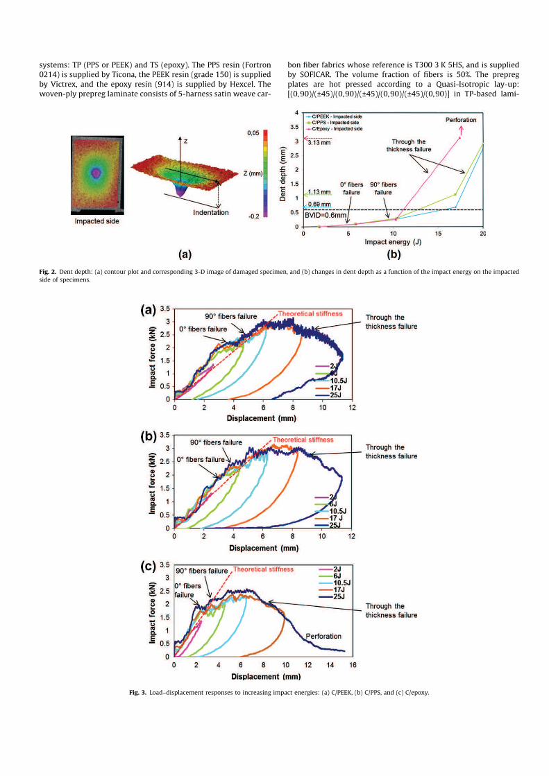
Fig. 2. Dent depth: (a) contour plot and corresponding 3-D image of damaged specimen, and (b) changes in dent depth as a function of the impact energy on the impacted
side of specimens.
Fig. 3. Load–displacement responses to increasing impact energies: (a) C/PEEK, (b) C/PPS, and (c) C/epoxy.

nates, and [(0,90)/(±45)/(±45)/(0,90)/(0,90)/(±45)/(±45)/(0,90)] inC/epoxy. The lay-up slightly differs in order to get similar lami-nates’ thicknesses. The laminates’ thickness was averaged frommeasurements at different points: 2.25 mm in C/PEEK, 2.29 mmin C/PPS, and 2.4 mm in C/epoxy laminates. The specimens werecut into 600 � 600 mm2 flat panels with a water-cooled diamondsaw. Specimens are 100 � 150 mm2 plates, and complies withthe standard Airbus AITM 1-0010, except for the recommendedthickness (4 mm). The main mechanical properties (see Table 1)of the three composite systems investigated in this work have beenevaluated in previous works [28,41,42].
3.2. Experimental procedure
Low velocity impact tests have been conducted at room temper-ature on the three composite materials for different impact ener-gies ranging from 2 J (vindentor � 1.4 m/s) to 25 J (vindentor � 5 m/s)such as: 2 J, 6 J, 10.5 J, 17 J, 25 J. The tests were conducted usinga guided drop weight tester characterized by a hemispherical steelindentor (diameter = 20 mm), and an impactor whose weight is2.077 kg (see Fig. 1). The drop tower also consists of an optical sen-sor used to evaluate the initial velocity before the impact, a piezo-electric force sensor to measure the impact load. Two specimenshave been tested in each configuration. According to the previousstandard, the BVID (Barely Visible Impact Damage) is defined by0.6 mm of indentation after relaxation of the structure and withoutbeing exposed to any humidity [43]. The data acquisition isachieved using a Yokogawa DL708 digital oscilloscope, which mon-itors two types of signals (force and intensity of the laser beam) at200 kHz frequency. Finally, the impact damage was assessed bysubsequent C-scan inspection and microscopic assessment of im-pacted specimens.
Fig. 4. Comparison of load–displacement curves for the three materials and every impact energy: (a) 2 J, (b) 6 J, (c) 10.5 J, (d) 17 J, and (e) 25 J.
Fig. 5. Observations of impact damage patterns on front and back sides of impacted
specimens as a function of the impact energy: (a) 6 J, (b) 10.5 J, (c) 17 J, and (d) 25 J.
4. Results
4.1. Permanent indentation
Laminates can absorb the impact energy by different meansincluding indentation (representative of local matrix crushingand local fiber breakage), delamination (inter-yarn fracture), split-ting (intra-yarn fracture) or fibers peeling on the non-impactedside [25,44,45]. For every impact energy, it appears that C/epoxypresents the highest ratio of dissipated energy compared with im-pact energy, whereas the energy dissipated during impact is virtu-ally the same in C/PPS and C/PEEK (see Table 2). Such a ratiousually increases to reach a maximum value at the onset of perfo-ration, as can be observed in the C/epoxy case [26]. The measure-ment of the specimen’s indentation is typically used to assess theimpact damage. In general, the indentation just after the impact(temporary indentation), is always higher than the indentationafter relaxation of the impacted composite. Such relaxation effectscan be neglected after 48 h to get the permanent indentation[45,46]. The indentation (see Fig. 2a), also called dent depth, is
measured using a dial indicator with an error of ±0.01 mm at sev-eral locations and according to different directions of the specimen.In TP-based laminates, the BVID (0.6 mm) is reached at about 13 J(C/PPS) and 16 J (C/PEEK), whereas it is reached at about 11 J in C/epoxy (see Fig. 2b).
4.2. Force–displacement curves
The force–displacement curves show the specimen’s stiffness(slope of the curve), the maximum displacement, and some infor-mation about damage for every impact energy (see Figs. 3 and 4).For the maximum impact energy (25 J), the force–displacementcurve can globally be divided into four main parts [45]. The firstpart of the curve is linear and represents the stiffness of the non-damaged specimen. For comparison purposes, the red-dotted linerepresents the theoretical stiffness calculated from the plates’ the-ory. At a force level of 2 kN and a deflection of 3 mm (for laminates’average thicknesses of about 2.3 mm), the load–deflection curvesof C/PEEK and C/PPS show a clear change in stiffness (see Fig. 3aand b), indicating damage initiation. In epoxy-based specimens,
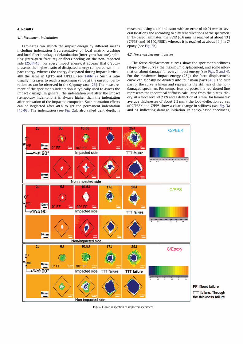
Fig. 6. C-scan inspection of impacted specimens.

stiffness changes for an impact force of about 2 kN (see Fig. 3c), anda deflection of the plate of about 2.8 mm (for laminates’ averagethicknesses of about 2.4 mm). The previous observations suggestthat damage appears as a result of the same impact forces in thestudied composite systems, indicating the start of the second part.Once the material’s stiffness has changed during low velocity im-pact tests, the profile of the force–displacement curve is uniqueto each material. However, a few common features can be ob-served in the three composite systems: the sawtooth profile isassociated with the specific impact damage that will be discussedfurther. At some point during the impact test and depending on theimpact energy, the maximum force borne by the laminates can bedetermined in the third part of the typical impact force–displace-ment curve. A threshold seems to appear at about 3 kN for 10.5 J,17 J and 25 J impact energies. On the one hand, the maximum forcereached in C/PPS is always equal or slightly higher than the onereached in C/PEEK. A maximum force threshold (about 3 kN) seemsto be reached at 17 J. On the other hand, C/epoxy laminates per-form similarly to TP composites from 2 J to 6 J impact energies.After this threshold, the force gradually decreases to reach the lastpart of the curve when the force becomes equal to zero. For higherimpact energies, there are two main differences: the force thresh-old is lower (2.4 kN), and the 25 J impact causes the specimen’sperforation, hence justifying a residual force at the end of the test.For a relevant comparison of the impact performance of the threematerials, force–displacement curves have been compared forevery impact energy (see Fig. 4). C/epoxy laminates present thelowest impact resistance for all impact energies, whereas TP-basedlaminates display a rather similar impact damage behaviors interms of force–displacement responses. The inflection and the sud-den drops (associated with a type of damage that will be discussedin the next section) observed on the force–displacement curves arevirtually the same for impact forces less than 2 kN. For higher forcelevels, the profile of these curves depends on specific impact dam-age scenarios which can be analyzed from the macroscopic obser-vations (see Fig. 5), the C-scan inspections (see Fig. 6), and themicroscopic observations of 0° and 90° cuts of impacted specimens(see Figs. 9–11). On the load–displacement curves, the dent depthof each material can be compared for every impact energy (seeFig. 4).
4.3. Macroscopic observations of impacted specimens
Macroscopic views of the front (impacted side) and the back(non-impacted side) of specimens give first information about theonset of damage as a function of the impact energy (see Fig. 5).The hemispherical indentor (impacted side), and the diamond-shaped fracture surface (non-impacted side), each correspondingto the maximum 25 J impact energy, are both represented on eachmacroscopic view. The scale has been adapted for each view in or-der to make the observed damages clearer. The 2 J impact does notcause important damage to specimens, whereas the 25 J impact in-duces the maximum damage in comparison to other energy levels.For the three materials, the onset of cracks along warp/weft direc-tions is observed on the non-impacted side of specimens from 6 Jimpact energy. On Fig. 5a these cracks are represented by red-dot-ted lines, and are referenced as transverse crack #1 (along the weftdirection) and longitudinal crack #2 (along the warp direction). At10.5 J, the length of cracks appearing at 6 J along warp/weft direc-tions has increased in all cases, but a new crack along the warpdirection can be observed in PPS-based specimens (see Fig. 5b). At17 J, the hemispherical indentation on the impacted side becomesclear (this is the first energy that creates an indentation over theBVID in TP specimens). In addition, fibers’ splitting starts generaliz-ing, and cracks along warp/weft directions significantly developedon the non-impacted side (see Fig. 5c). A 17 J impact importantly
penetrates C/epoxy laminates, and the main 90° crack is longer onthe non-impacted side, whereas a new crack has appeared alongthe warp direction. On the non-impacted side of PEEK-based spec-imens, there are also new cracks along warp/weft directions, and across-shape fracture surface can be observed. Lastly, the 25 J impactimportantly penetrates C/PEEK and C/PPS laminates, and perforatesC/epoxy laminates (see Fig. 5d). The non-impacted side of all spec-imens can be characterized by diamond-shaped fracture surfaces.
4.4. Post impact C-scan inspections
The C-scan maps of impacted specimens provide further infor-mation on the damage mechanisms (see Fig. 6), and more particu-larly they are often used to calculate the delaminated area (seeTable 3) which is related to the dissipation of energy during the im-
Fig. 8. Changes in the delaminated areas resulting from C-scan results as a function
of impact energy.
Fig. 7. Comparison of C-scan maps and impact damage patterns on front and back
sides of specimens impacted at 17 J: (a) C/PEEK, (b) C/PPS, and (c) C/epoxy.

pact (see Table 2). On each C-scan map is represented by either thehemispherical indentor (impacted side) or the diamond-shapedfracture surface (non-impacted side) corresponding to the 25 J im-pact energy. For each material, the damage area is similar on bothimpacted/non-impacted sides of laminates. C/epoxy specimens al-ways display larger delaminated areas than TP-based composites,reaching values about twice as high for low impact energies. Forhigher impact energies, the relative difference in delaminatedareas remains significant (about 70%) when comparing C/epoxyand C/PPS impacted specimens (see Fig. 8). The comparison ofepoxy- and PEEK-based laminates shows that the relative differ-ence in delaminated areas decreases as impact energy increasesgoing from +40% (17 J) to only +10% (25 J). Finally, the delaminatedarea is considerably more expanded in C/PEEK than in C/PPSlaminates (+25% at 17 J–+50% at 25 J). As a conclusion to thissection, it appears that C/epoxy is prone to delamination duringlow-velocity impacts. It turns out that PEEK-based specimens tendto delaminate to an increasing extent at increasing impact energy,whereas PPS-based laminates display limited delamination.
5. Analysis and discussion
5.1. About the influence of the mesostructure on the impact damage
mechanisms
The primary impact failure mechanisms are a very complexcombination of energy absorption mechanisms such as delamina-
tion predominantly caused bymodes I–II interlaminar shear matrixcracking, and intralaminar fracture in terms of fiber fracture andkinking or splitting [11]. In woven-ply laminates, the fiber bundlescrimps cause local stress perturbations under uniaxial tension,which lead to the concentration of large normal and shear strains.These strains concentrations may result in early damage initiationin the form of fiber/matrix interface debonding or matrix cracking.Even though the weave structure prevents the fiber bundles frommigrating into the interply layer during fabrication, the deviationof fabric surface from planarity introduces macroscopic roughness,depending on the fabric thickness as well as the weaving patterns.The roughness of fabrics perpendicular to the direction of crackgrowth also promotes the creation of a larger fracture–surface area,and matrix-rich regions at the crimps between warp/weft yarnsand between laminates’ plies. These matrix-rich regions seem toplay an important role in the impact behavior as it will be discussedfurther. During low velocity impacts, the first type of damage ismatrix cracking, which does not significantly change the overallstiffness of laminates [2,27]. Such damage depends on the ultimateout-of-plane (suxz) and in-plane (suxz) shear strengths respectively[28]. In order to investigate the impact mechanisms associatedwith the tested material, it is therefore necessary to compare theirultimate shear strengths (see Table 1): suxz is 54% and 22% higher inC/PEEK laminates with respect to C/PPS and C/epoxy respectively,whereas suxz is about 30% higher. At some point during the impactdamage process, lots of intralaminar and inter-yarn cracks appear,and ultimately coalesce to create a pyramidal damage (see Figs. 9–
Fig. 9. Microscopic observations of C/PEEK specimens impacted at 17 J.
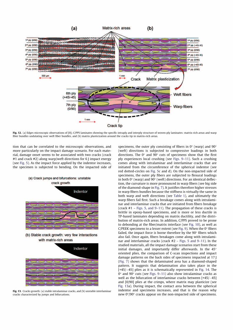
11). These cracks are important because cracks tips are known toact as onset sites for delamination and fiber breakages whichchange the local stiffness of laminates. As these cracks propagate(in mode I and mode II), they interact with matrix-rich regionsand the weave structure (see Fig. 13), resulting in substantial crackgrowth resistance and a better resistance to delamination, subse-quent to the interlaminar fracture toughness, as it was highlightedin the literature [11,29,32]. The stress concentration at the cracktips leads to the creation of a plastic zone, whose expansion mainlydepends on the matrix ductility, and is restricted by the bond-linethickness between adjacent layers (see Fig. 12). Thus, for a givenimpact force, the plasticization of the matrix starts earlier in C/PPS, and is more expanded than in C/PEEK and C/epoxy laminatesin which plasticization is limited (see yield strengths in Table 1).As a result, the potential benefit of matrix-rich regions in woven-fabric laminates is the development of a significantly large plasticyield zone at the cracks tip as intralaminar and interlaminar crackspropagate [11]. It also means that the modes I and II interlaminarfractures toughness play important roles in determining the impactdamage behavior of composites as previously reported [25]. In or-der to discuss the impact damage scenarios, it seems therefore rel-evant to recall the fracture toughness GIc of neat resins, and theinterlaminar fracture toughness GIc and GIIc of woven-fabric lami-nates (see Table 3). As far the mode I interlaminar fracture is con-cerned, C/PEEK laminates are about twice tougher than C/PPS, and6 times tougher than C/epoxy. From the GIIc standpoint, C/PEEKlaminates are about 3 times tougher than C/PPS and C/epoxy. Itmeans therefore that the intrinsic toughness of TP-based resins is
not entirely beneficial to the reinforced polymer, and depends onhow the matrix can modify the interlaminar fracture within the fi-ber network. As far the neat resin is concerned, the mode I inter-laminar fracture is 8 times and 40 times higher in PEEK resin incomparison to PPS and epoxy resins respectively (see Table 3).Lastly, the low interlaminar toughness of epoxy-based laminatesis consistent with the extensive delamination observed in thesespecimens (see Fig. 11). As a conclusion on the importance of inter-laminar fracture toughness on the impact behavior, two distinctmodes of failure were reported in the literature: a cleavage modecorresponding to fast crack propagation, in epoxy-based laminateswhose mode I interlaminar fractures toughness is low (see Table 3),and a ductile mode corresponding to slow crack propagation, forTP-based laminates with a much higher GIc [47]. The mode II inter-laminar fracture can be associated with a combination of stablecrack growth preceding unstable crack growth, and matrix plastici-zation at the crack tips, depending on matrix ductility [48]. It couldexplain why the delaminated areas are larger in C/epoxy and C/PEEK than in PPS-based laminates. Lastly, it was generally observedthat matrix-rich areas and a strong interface bond promote unsta-ble inter-laminar crack propagation (see Fig. 13a), whereas matrix-poor areas and a weak interface bond results in stable crack prop-agation through intralaminar cracks and possible debonding (seeFig. 13b). In addition to the toughness of the matrix, the crackgrowth may also be ascribed to the structure of the fiber network.The delamination crack at the woven-fabric laminate interface nor-mally had multiple crack fronts, one for each warp yarn [11]. Oncethe crack propagation became rather unstable at a sudden load
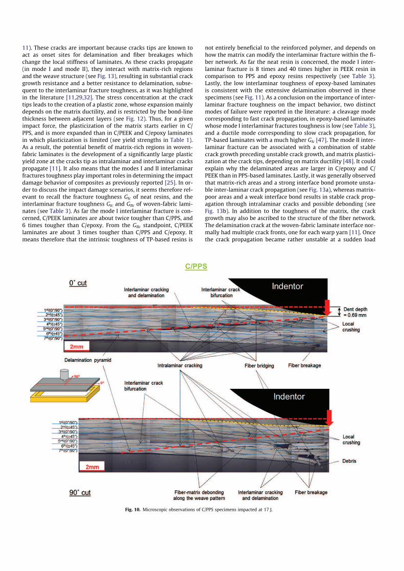
Fig. 10. Microscopic observations of C/PPS specimens impacted at 17 J.

drop on the force–displacement curve (see Fig. 3b), the whole crackfront jumped forward which was then immediately arrested at thenext undulation forming a continuous crack front (see Fig. 13a).The same mechanisms can generalize more or less as cracks prop-agate, until complete delamination of the laminate. In addition, theyarns transverse to the crack propagation direction also lead tointerlaminar crack bifurcation and intralaminar cracking (see Figs.9–11). These failure mechanisms are particularly instrumental inpromoting fiber-bridging frequently taking place across the frac-ture surfaces. Indeed, when laminates are impacted to such a de-gree that matrix cracks just occur and begin to propagate, thecracks can propagate without breaking the fibers. Then, when thematrix cracks open, the intact fibers crossing the crack may closethem, which are called fiber-bridging, on the crack surfaces andthus reduce the crack-opening-displacement and the stress inten-sity factors at the crack tips. Fiber-bridging mechanisms comprisedebonding along the interfaces of matrix and bridging fibers, andfrictional sliding along the debonded part of the interfaces. The
bridging of macro-cracks by fibers only partially pulled out is animportant source of toughness [49], and this mechanism is morelikely to occur in tougher matrices, hence in TP-based laminates[28,29].
5.2. Impact damage scenarios
The impacted specimens have been enrobed by an inclusion re-sin in order to prevent the relaxation of the damaged parts aftercutting them. The microscopic observations of 0° and 90° cuts ofimpacted specimens have been carried out in order to explainthe creation and propagation of the damage during these tests.Only the observations associated with a 17 J impact are presentedin this section, because they are representative enough of all thetypes damages within the impacted laminates, and because theBVID is reached for the three materials at this energy level. Inaddition, the comparison between macroscopic observations andC-scan maps (see Fig. 7) gives qualitative and quantitative informa-
Fig. 11. Microscopic observations of C/epoxy specimens impacted at 17 J.
Table 3
Interlaminar fracture toughness of tested materials – dent depth and delaminated surface for a 17 J impact energy.
C/PEEK C/PPS C/epoxy (914)
GIc (kJ/m2) neat resin 4 [43] 0.5–0.9 [43] 0.1 [7]
GIc,initiation (kJ/m2) carbon fiber woven-ply polymer 1.1–2.1 [29] 0.85–1 [25,28] 0.35–0.5 [32,34]
GIIc,initiation (kJ/m2) carbon fiber woven-ply polymer 2–4.9 [30,44] 1.8 [28] 1.5 [11]
Dent depth at 17 J (mm) impacted side 0.69 1.13 3.13
Delaminated surface at 17 J (mm2) 900 600 978
tion that can be correlated to the microscopic observations, andmore particularly on the impact damage scenario. For each mate-rial, damage onset seems to be associated with two cracks (crack#1 and crack #2) along warp/weft directions for 6 J impact energy(see Fig. 5). As the impact force applied by the indentor increases,the specimen is subjected to bending. On the impacted side of
specimens, the outer ply consisting of fibers in 0° (warp) and 90°(weft) directions is subjected to compressive loadings in bothdirections. The 0° and 90° cuts of specimens show that the firstply experiences local crushing (see Figs. 9–11). Such a crushingcomes along with intralaminar and interlaminar cracks that areinitiated from the circumference of the spherical indentor (seered dotted-circles on Fig. 5c and d). On the non-impacted side ofspecimens, the outer ply fibers are subjected to flexural loadingsin both 0° (warp) and 90° (weft) directions. For an identical deflec-tion, the curvature is more pronounced in warp fibers (see big sideof the diamond-shape in Fig. 7). It justifies therefore higher stressesin warp fibers bundles because the stiffness is virtually the same inboth warp and weft directions (see Table 1), and ultimately thewarp fibers fail first. Such a breakage comes along with intralami-nar and interlaminar cracks that are initiated from fibers breakage(crack #1 – Figs. 5, and 9–11). The propagation of these cracks isbrittle in epoxy-based specimens, and is more or less ductile inTP-based laminates depending on matrix ductility, and the distri-bution of matrix-rich areas. In addition, C/PPS proved to be proneto debonding at the fiber/matrix interface (see Fig. 10), as well asC/PEEK specimens to a lesser extent (see Fig. 9). When the 0° fibersfailed, the impact force is borne therefore by the 90° fibers whichalso fail. Once again, fibers breakages come along with intralami-nar and interlaminar cracks (crack #2 – Figs. 5 and 9–11). In thestudied materials, all the impact damage scenarios start from theseinitial damages, and importantly differ afterwards. In the 45°oriented plies, the comparison of C-scan inspections and impactdamage patterns on the back sides of specimens impacted at 17 J(Fig. 7) shows that the delaminated area has a diamond-shapedpattern. It suggests that delamination also takes place in the[+45/ÿ45] plies as it is schematically represented in Fig. 14. The0° and 90° cuts (see Figs. 9–11) also show intralaminar cracks aswell as the bifurcation of interlaminar cracks between [+45/ÿ45]and [0/90] plies at the crimps, where matrix may plasticize (seeFig. 13a). During impact, the contact area between the sphericalindentor and specimens increases, and that is the reason whynew 0°/90° cracks appear on the non-impacted side of specimens.
Fig. 12. (a) Edges microscopic observations of [0]7 C/PPS laminates showing the specific intraply and interply structure of woven-ply laminates: matrix-rich areas and warp
fiber bundles undulating over weft fiber bundles, and (b) matrix plasticization around the cracks tip in matrix-rich areas.
Fig. 13. Cracks growth: (a) stable intralaminar cracks, and (b) unstable interlaminar
cracks characterized by jumps and bifurcations.

Thus, the mechanisms described above are going to generalize spe-cifically in the laminates plies according to their orientation. Thus,intralaminar and interlaminar cracks are going to develop, propa-gate and coalesce in a pyramidal shape which will expand fromthe non-impacted side to the impacted side, as it can be observedin the 0° and 90° microscopic cuts of the tested materials (repre-sented by an inclined red-dotted line in Figs. 9–11). This pyramidaldamage is clearly observable in TP-based specimens, and moreparticularly in C/PEEK, but is less easy to define in epoxy-basedlaminates. On the non-impacted side of specimens, the diamond-shaped damage results from the gradual breakage of fibers in warpand weft directions, and can be clearly observed at 25 J (seeFig. 5d). At increasing impact energy, the significant changes inthe permanent indentation (see Fig. 2b) may be ascribed to theextension of this pyramidal damage along the 0° and 90° direc-tions. Indeed, as the normal displacement increases during impact,the cracks localized along the pyramid axis open wider through thelaminates’ thickness, and grow in both warp and weft directions(by mode I and mode II failure) at increasing impact energy.Coming along with the pyramidal damage extension, delaminationonset can be observed between the last two outer plies of thelaminates. It develops therefore throughout the width of the spec-imens (in the 90° direction – mode III shearing failure). Impact in-duced damages are schematically represented on Fig. 14. Based onthe microscopic observations in the 0° and 90° directions, the dam-age mechanisms importantly differ from one material to another.In C/PEEK laminates, the initial damage consists in matrix crackingfrom which intralaminar and interlaminar cracks are initiatedalong the warp and weft directions. As the impact force increases,these cracks propagate. As the ultimate out-of-plane shearstrength is significantly higher in C/PEEK specimens (see Table1), there is relatively less shear matrix cracking in comparison to
C/PPS and C/epoxy laminates (see Fig. 14). As a consequence, fibersbear most of the impact force and eventually fail, hence justifying across-shape pattern on the non-impacted side. Contrary to C/PEEKlaminates, the low ultimate out-of-plane shear strength of C/PPSlaminates leads to matrix plasticization in matrix-rich areas andthen shear matrix cracking, whereas it seems there is relatively lessfibers failure in warp and weft directions. In 5-harness satin weaveC/PPS laminates (the exact samematerial than the one investigatedin this work), sudden jumps in the force–displacement curves andunstable crack propagation in mode I have been observed [28]. Themode II crack propagation also proved to be stable for reasons ofmatrix plasticization at the crack tips. Such an effect could alsobe associated with the weak adhesion at the fiber/matrix interface[42], resulting in an extensive debonding and fiber-bridging at thewake of cracks front (see Fig. 14). Finally, in C/epoxy laminates,there is relatively little damage on the upper ply (see Fig. 5),because an extensive delamination appears throughout thelaminate’s thickness at increasing impact energy. Thus, the out-of-plane displacement associated with delamination is greater,and the impact force borne by C/epoxy specimens is lower thanthe one in TP-based laminates (see Fig. 3). Microscopic observa-tions of 0° and 90° cuts revealed debonding of transversely ori-ented yarns at the crack plane, and crack branching around thedebonded yarn. Debonding was found to occur periodically andwas identified as a mechanism contributing to the fracture work.No indications of fiber-bridging were observed in the 5H-satinweave carbon/epoxy composites (see Figs. 11 and 14).
5.3. Permanent indentation
From the damage mechanisms described above result a perma-nent indentation (see Fig. 2b). Another factor contributing to the
Fig. 14. Schematic representation of impact induced damages: (a) C/PEEK, (b) C/PPS, and (c) C/epoxy.
increase of dent depth is the development of the diamond-shapeddamage on the non-impacted side particularly in C/epoxy speci-mens and in C/PPS laminates to a lesser extent. Firstly, and partic-ularly in the case of TP-based laminates, the matrix plasticizationseems to play an important role in matrix-rich areas by locallyleading to permanent deformations, hence contributing to the per-manent indentation. Secondly, the permanent indentation seemsto be reduced by the presence of fiber-bridging as it can be ob-served in TP-based laminates. Bridges prevent the plies from open-ing in mode I, and slow down the propagation of interlaminar andintralaminar cracks in modes II–III, ultimately reducing theirextension and subsequent delamination for a given impact energy.Finally, while fibers gradually fail and cracks propagate in the 0°and 90° directions, the out-of-plane shearing of the layers localizedunder the damage pyramid lets the debris of broken fibers and ma-trix get in the fracture surface (see Figs. 9–11). These debris getstuck in these cracks and the adjacent layers, and create a sort ofblocking system that prevents the broken parts of the specimenfrom getting back to zero level after the impact. The longer thecracks are, the more the debris can get in, creating a diamond-shaped mark on the non-impacted side of the specimen, hencethe permanent indentation. These mechanisms are instrumentalin forming the BVID which is fundamental in damage tolerance[45].
6. Conclusion
From the present comparative study on the low velocity impactbehavior of carbon woven-ply reinforced polymer composites, itresults that C/epoxy laminates experience larger delaminationthan TP-based laminates. C/TP laminates are characterized by re-duced damages (C/PPS laminates in particular), confirming that atougher matrix can possibly be associated with better impact per-formances. In addition to the nature of the matrix, the reinforce-ment weave structure limits extensive growth of delamination,but fiber breakages are more common and appear at lower impactenergies because of fiber crimps. The features and advantageousfailure mechanisms are identified: inherent toughness of the fab-ric; the availability of matrix-rich regions at the fiber bundlescrimp where plastic deformation can develop (in C/TP laminates);crack propagation along the undulating pattern of the yarns creat-ing a large fracture surface area; and multiple crack delaminationon the impacted side (particularly in epoxy-based laminates). InTP-based laminates, impact damage scenarios are similar at lowimpact energies. The delamination failure comes along with inter-laminar and intralaminar cracks. They appear to be mode I failuremechanisms, defining a delamination pyramid under the impactor.As the impact energy increases, the cracks propagation seems to bedriven by mode II and mode III shearing modes beyond this delam-ination pyramid. These failure mechanisms depend on many fac-tors including the ultimate out-of-plane shear strength (higher inPEEK-based laminates) resulting in a more or less pronounced ma-trix plasticization at the crack tips. The interlaminar fracturetoughness in modes I–II–III (reduced in epoxy-based laminates)is associated with possible fiber-bridging (not observed inC/epoxy). C/PEEK is therefore relatively less prone to shear matrixcracking, hence justifying a cross-shape pattern on the non-impacted side when they fail. The poor fiber/matrix adhesion inC/PPS laminates results in an extensive debonding, and fiber-bridging at the wake of cracks front. It could explain why the del-aminated areas are larger in C/epoxy and C/PEEK than in PPS-basedlaminates. Lastly, the permanent indentation can be mainly as-cribed to different mechanisms. On the one hand, the matrix plas-ticization seems to play an important role in matrix-rich areas bylocally promoting permanent deformations in TP-based laminates.
On the other hand, fiber-bridging prevents the plies from openingin mode I, and slows down the propagation of interlaminar andintralaminar cracks in modes II–III. It reduces therefore theirextension and subsequent delamination for a given impact energy.Finally, the debris of broken fibers and matrix get stuck in thecracks and the adjacent layers (particularly in C/epoxy laminates),and create a sort of blocking system that prevents the cracks anddelamination from closing after impact.
References
[1] Hancox NL. An overview of the impact behavior of fibre-reinforced composites.In: Reid SR, Zhou G, editors. Impact behavior of fiber-reinforced compositematerials and structures. CRC Press, Woodhead Pub. Ltd.; 2000.
[2] Cantwell WJ, Morton J. The impact resistance of composite materials—areview. Composites 1991;22(5):347–62.
[3] Jang BP, Kowbel W, Jang BZ. Impact behavior and impact-fatigue testing ofpolymer composites. Compos Sci Technol 1992;44(2):107–18.
[4] Abrate S. Impact on composites structures. Cambridge University Press; 1998.[5] Bibo GA, Leicy D, Hogg PJ, Kemp M. High-temperature damage tolerance of
CRFP. Part 1: impact characteristics. Composites 1994;25(6):414–24.[6] Bibo GA, Hogg PJ, Kemp M. High-temperature damage tolerance of CRFP: 2.
Post-impact compression characteristics. Composites 1995;26(2):91–102.[7] Jang BP, Huang CT, Hsieh CY, Kowbel W, Jang BZ. Repeated impact failure of
continuous fiber reinforced thermoplastic and thermoset composites. JCompos Mater 1991;25(9):1171–203.
[8] Ishikawa T, Sugimoto S, Matsushima M, Hayashi Y. Some experimentalfindings in CAI tests of CF/PEEK and conventional CF/epoxy flat plates.Compos Sci Technol 1995;55:349–63.
[9] Davies P, Riou L, Mazeas F, Warnier P. Thermoplastic composite cylinders forunderwater applications. J Thermoplast Compos Mater 2005;18(5):417–43.
[10] Schrauwen B, Peijs T. Influence of matrix ductility and fibre architecture on therepeated impact response of glass-fibre-reinforced laminated composites.Appl Compos Mater 2002;9(6):331–52.
[11] Kim J-K, Sham M-L. Impact and delamination failure of woven-fabriccomposites. Compos Sci Technol 2000;60:745–61.
[12] Bibo GA, Hogg PJ. Review: the role of reinforcement architecture in impactdamage mechanisms and post-impact compression behavior. J Mater Sci1996;31:1115–37.
[13] Mili F, Necib B. Impact behavior of cross-ply laminated composite plates underlow velocities. Compos Struct 2001;51(3):237–44.
[14] Aktasß M, Atas C, _Içten BM, Karakuzu R. An experimental investigation of theimpact response of composite laminates. Compos Struct 2009;87(4):307–13.
[15] Reis PNB, Ferreira JAM, Santos P, Richardson MOW, Santos JB. Impact responseof Kevlar composites with filled epoxy matrix. Compos Struct2012;94(12):3520–8.
[16] Morton J, Godwin EW. Impact response of tough carbon fibre composites.Compos Struct 1989;13(1):1–19.
[17] Prevorsek DC, Chin HB, Bhatnagar A. Damage tolerance. Design for structuralintegrity and penetration. Compos Struct 1993;23(2):137–48.
[18] Bartus SD, Vaidya UK. Performance of long fiber reinforced thermoplasticssubjected to transverse intermediate velocity blunt object impact. ComposStruct 2005;67(3):263–77.
[19] Reyes G, Sharma U. Modeling and damage repair of woven thermoplasticcomposites subjected to low velocity impact. Compos Struct2010;92(2):523–31.
[20] Ghasemi Nejhad MN, Parvizi-Majidi A. Impact behaviour and damagetolerance of woven carbon fibre-reinforced TP composites. Composites1990;21(2):155–68.
[21] Wang H, Vu-Khanh T. Damage extension in carbon fiber/PEEK cross plylaminates under low velocity impact. J Compos Mater 1994;28(8):684–707.
[22] Gao S-L, Kim J-K. Cooling rate influence in carbon fibre/PEEK composites. PartIII: impact damage performance. Composites A 2001;32(6):775–85.
[23] Aymerich F, Priolo P, Vacca D. Static loading and low-velocity impactcharacterization of graphite/PEEK laminates. In: Proceedings of theinternational conference on advanced mater, Hurghada, Egypt; 1998.
[24] Vedula M, Koczak MJ. Impact resistance of cross-plied polyphenylene sulfidecomposites. J Thermoplast Compos Mater 1989;2(3):154–63.
[25] Spamer GT, Brink NO. Investigation of the CAI properties of C/PPS and C/APC-2TP materials. In: Proceedings of the 33rd international SAMPE symposium:materials-pathway to the, future; 1988.
[26] Ma C-CM, Lee C-L, Chang M-J, Tai N-H. Effect of physical aging on thetoughness of CFR PEEK and PPS composites. Polym Compos 1992;13(6):441–7.
[27] Davies GAO. Design methodology to improve damage tolerance in composites.In: Brite Euram 3159-89 contract report, second ed., Dept. of Aeronautics,Imperial College, London; 1993.
[28] De Baere I, Jacques S, Van Paepegem W, Degrieck J. Study of the mode I andmode II interlaminar behavior of a carbon fabric reinforced TP. Polym Test2012;31(2):322–32.
[29] Davies P, Benzeggagh ML, De Charentenay FX. The delamination behavior ofcarbon fiber reinforced PPS. In: 32nd International SAMPE, symposium; 1987.p. 134–46.
[30] Lachaud F, Lorrain B, Michel L, Barriol R. Experimental and numerical study ofdelamination caused by local buckling of TP and TS composites. Compos SciTechnol 1997;58:727–33.
[31] O’Brien K. Composite interlaminar shear fracture toughness giic: shearmeasurement or sheer myth? Tech Memorandum, NASA; 1997.
[32] Alif N, Carlsson LA, Boogh L. The effect of weave pattern and crack propagationdirection on mode I delamination resistance of woven carbon composites.Composites B 1998;29:603–11.
[33] Kim J-K, Leung LM, Lee SWR, Hirai Y. Impact performance of a woven fabricCFRP laminate. Polym Compos 1996;4:549–61.
[34] Funk JG, Deaton JW. The interlaminar fracture toughness of woven graphite/epoxy composites. NASA tech paper 2950; 1989.
[35] Siow YP, Shim VPW. An experimental study of low velocity impact damage inwoven fiber composites. J Compos Mater 1998;32(12):1178–202.
[36] Jegley DC. Compression behavior of graphite–thermoplastic and graphite–epoxy panels with circular holes or impact damage. NASA tech paper, 3071;1991.
[37] Baker DJ. Mechanical property characterization and impact resistance ofselected graphite/PEEK composite materials. NASA tech Memorandum102769, AVSCOM tech, report 90-B-012; 1991.
[38] Atas C, Sayman O. An overall view on impact response of woven fabriccomposite plates. Compos Struct 2008;82(3):336–45.
[39] Karaoglan L, Noor AK, Kim YH. Frictional contact/impact response of textilecomposite structures. Compos Struct 1997;37(2):269–80.
[40] Chaudhuri J, Ghoe GH, Vinson JR. Impact characterization of graphite fiberreinforced thermoplastic laminates. J Reinf Plastics Comp 1993;12(6):67–685.
[41] Aucher J, Vieille B, Taleb L. Influence de la température sur le comportementmécanique de stratifiés tissés thermoplastique ou thermodurcissable. RevComp Mater Av 2011;21(3):317–43.
[42] Vieille B, Aucher J, Taleb L. Woven ply thermoplastic laminates under severeconditions: notched laminates and bolted joints. Composites B2011;42(3):341–9.
[43] Tropis A, Thomas M, Bounie JL, Lafon P. Certification of the composite outerwing of the ATR72. J Aero Eng 1994;209:327–39.
[44] Akkerman R, Warnet LL, Van de Ven EC. Impact damage in woven fabricreinforced composites. In: Proceedings of the 10th international conference ontextile comp TEXCOMP’10, Lille, France; October 2010.
[45] Abdallah EA, Bouvet C, Rivallant S, Broll B, Barrau J-J. Experimental analysis ofdamage creation and permanent indentation on highly oriented plates.Compos Sci Technol 2009;69:1238–45.
[46] Berglund LA. Thermoplastic resins. In: Peters ST, editor. Handbook ofcomposites. London: Chapman & Hall; 1998.
[47] Moore DR, Seferis JC. Toughness characterization of carbon fiber PEEKlaminates. Pure Appl Chem 1991;63(11):1609–25.
[48] Carlsson LA, Gillespie JW, Trethewey BR. Mode II interlaminar fracture ofgraphite/epoxy and graphite/PEEK. J Reinf Plastics Comp 1986;5(3):170–87.
[49] Kardomateas GA, Carlson RL. A micromechanical model for the fiberbridging of macro-cracks in composite plates. J Appl Mech 1996;63:225–33.