opel manta/ascona/1900 wiring diagram - goin design · · 2006-05-09for example a 14 ga. wire...
TRANSCRIPT

I.E. if wire is labeled (14 Blue #), then the original wire was a Blue 14 GA. Wire. If you can not match color, make sure to use
NOTES:
2. (12 Red#) = Wires labeled with a # are not in EZ-Wiring Harness, you will have to add to harness, match existing wire code if possible.
* = See Note
4. On Front Harness, Headlight/Parking light circuits are labels as Left only out of he Fuse Box, Right hand wires are at the end of the harness.
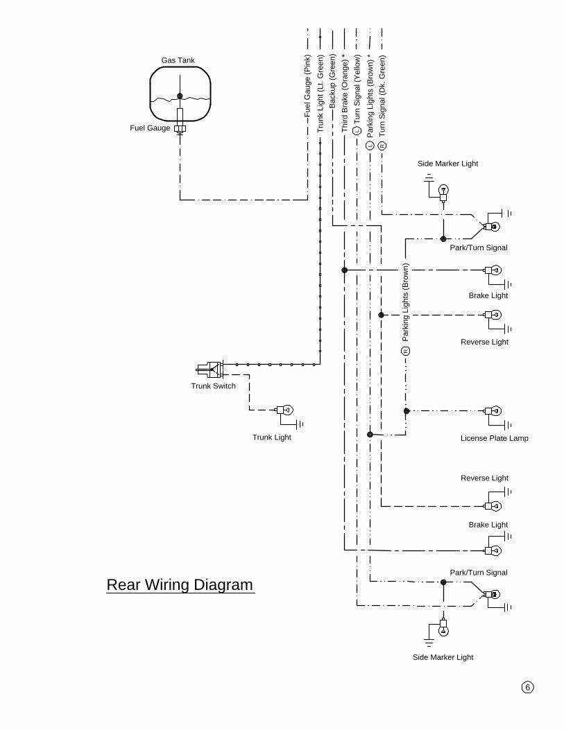
5. On Rear Harness, the parking light circuit is labeled as Left coming out of the fuse box, Right hand wires are at the end of the harness.
are run spliced into this circuit.6. Braking Light Circuit is labeled as "Third Brake Light" coming out of the fuse box, there are no Left or Right wires for this circuit. As they
1. Relay optional, If not installing a relay to protect the ignition switch, ignore the relay circuit.
the same gauge or larger. For example a 14 ga. wire could replace a 16 ga., for a 16 ga. wire, you could use 14 ga., but not 18 ga.
Brake Switch (White), Power Antenna (Purple), etc..) They can be either used for other accesories or cut at fuse box.3. Some extra wires maybe found in the wiring harness (Window Power (Yellow), Door Lock Power (Yellow),
Opel Manta/Ascona/1900 Wiring Diagram
Legend:
Misc. / Control Circuits
Turn Signal Circuits
Parking Light Circuits
Low Beam / Brakes Light Circuit
L
R
High Beam / Back-Up Light Circuit
Primary Power Circuits
Ignition Circuit
Wire Labeled as Right
Wire Labeled as Left
Ground Wire
Index:1 - Notes, Legend, & Shipping Check List
2 - Fuse Box Diagram3 - Front Wiring Diagram4 - Dash Harness Diagram5 - Column Harness Diagram6 - Rear Wiring Diagram7 - Ignition and Charging Wiring Diagram & Notes
This Kit Contains(1) Prewired Fuse Panel w/ 20 Fuses
(2) Prewired Headlight Plugs(1) Prewired Late GM Alternator Plug (2) Prewired GM Column Ignition Switch Plugs(1) Prewired Dimmer Switch Plug(2) Prewired GM Turn Signal Connectors
(1) Large Grommet
(3) Loose Wires
(8) Yellow Splice Connectors(6) Blue Splice Connectors(6) Small Blue Lugs
(1) Fusible Link (3" Black Wire w/ Ring Terminal)
(5) Medium Yellow Lugs
(2) Prewired Flasher Units (1) Prewired Horn Relay
i thru v - Instructions, Dos and Don'ts
(Based on using Universal EZ20 wiring harness)

These instructions were developed after installing this system into many different vehicles and should make the this a quick and EZ Job.
Instructions (READ Before proceeding)
Please Remember that these are General Directions , for your unique and specific vehicle you will need to modify them. Whenever using after-market or specialty equipment such as Electric Windows, Power Mirrors, etc..., always use the diagrams provided with that equipment. Circuits are provided for these type of items in the harness, i.e.. Power Window (Yellow ), and are the (+) power lead called for in your diagram. Ground (-) can be simply a wire running from your controls to the body of the car.
This instruction booklet and its diagrams refer to the labeled and color coded wires in the harness by label and then its color, i.e. Power Antenna (Purple). If a diagram shows only a label then that wire is not provided in this harness, i.e. Ground. We recommend use of 14 gauge black wire for ground wires. To aid you we have highlighted important items and provided general diagrams for Ford, GM and MOPAR.
The Diagrams are based on the 4 basic sections of the wiring harness as it is shipped from the factory. They are the Front Section, Dash Section, Column Section and Rear Section . They are to help guide you as to which wires are in which section of the harness.
For each section compare the wires in the harness to the layout of your car and its wiring harness. If rewiring a classic vehicle, review the original factory wiring diagrams and compare the two diagrams for circuits not in the EZ Harness, or circuits that are in the harness that you will not be needing.
Should the design of your vehicle require relocating wires note it on the diagram. An example of this would be if your wiper motor is mounted in the engine bay and not under the dash. In that case you would have to move the Wiper Power (Dk. Blue) wire out of the Dash harness and relocate it to the front harness. In this case, it would also be the time you traced your wiper control diagram in your factory wiring diagram and see if extra wires are required. It is best when adding wires to the harness for model specific systems to try to best match the color and gauge of the wire in the original harness to match the factory wiring diagram.
You will also find there are many extra wires and circuits in the harness you may not need, feel free to reuse them for other circuits. Be careful, follow the diagram and if the wires you plan to reuse are coming from the fuse box they will be hot (+), if you need to reuse a wire in the harness for a control wire be sure to cut it off the fuse box and tape it off. I.E., the Fan (Gray) wire could be used as a control wire for the wiper circuit, instead of removing it if you don't plan on installing a electric radiator fan, but it would need to be disconnected from the fuse box before you used it for that purpose, or if you needed a extra power lead in the front for a washer fluid pump, it could be used for that without having to cut it back at the fuse box since you want it to be a (+) lead. No matter what you do, be sure to document any of these changes on the appropriate diagram.
preplanning
i
Preface

Clear a Large Work Area to spread out the harness, the area next to the vehicle would be good place. Your harness as delivered to you will have each of the 4 sections coiled and tied together with cable ties. When working with the harness it is very important that you do not remove the 3 cable ties closest to the fuse panel.
¦ Set the Fuse Panel in the center of the work area.
¦ Start with the largest coil of wires. This will be the Front Section. Remove the cable ties and uncoil towards the front of the vehicle.
¦ The next largest will be the Rear Section Remove the cable ties and uncoil this toward the back of the vehicle.
¦ The next coil would be the Dash Section, it will be the section without the relays Remove the cable ties and uncoil this to the side of the fuse panel.
¦ Last is the Column Section, more than likely you will not have to modify this section So leave as is and put it to the side.
Now using the diagrams and notes from your preplanning, work on section at a time, and start removing any unused wires. Remove one wire at a time pulling them through the remaining harness cable ties. Remember do not remove the 3 ties nearest the fuse panel. Unused wires that come directly from the fuse panel are hot (+) leads and should be cut as close as possible to the back of the panel. Use Caution and only cut wires that you are sure you will never need again.,
After removing all unused wires from all sections, move on to those wires you needed to move from one section to the other. Working one wire at a time move these wires to their new sections by pulling them out of their original section and rerouting them through the harness ties into their new sections.
Now you will need to add the wires not included in the kit. Work one circuit at a time, one section at a time. As mentioned in preplanning you can reuse wire that you removed earlier, be sure to Keep Notes so as not to get confused.
The last step is to compare the diagrams, and notes you made during preplanning and compare to the final harness. If everything is accounted for use cable ties and recoil the sections one at a time. I found it helped to bundle smaller circuits within a section together first before I bundled the complete section together, i.e. charging system, ignition circuit, gauge wires, etc. If the ties nearest the panel are loose either tighten them or replace them as necessary.
Preparing the Harness for Installation
ii
Instructions (Part 2)

The Fuse Panel is designed to be mounted under the dash on the drivers side of the vehicle.
The Fuse Panel should be mounted securely to a flat surface. Care should be taken to keep it and the wires away from any moving parts such as the gas or brake controls, wiper assembly, etc. The Panel should be accessible in case you ever blow a fuse. When locating the fuse panel, be sure that the steering column section will still reach the column. After selecting the location for the fuse panel, determine the best location for the horn relay and flasher units. Be sure to locate in an accessible location in case you should need to replace a flasher or relay later.
Now that the fuse panel and relays are mounted, note where the front wires exit the panel. Find a spot on the fire wall where the wires can enter the engine compartment without interfering with other components such as brake boosters, wipers, steering gears, etc.. at that spot drill a 1 1
4" hole and install the large grommet that came with the kit. As the last step, remove the cable ties you put on the front section wires and pass them through the grommet into the engine compartment one wire at a time. After all the wires are through the grommet, pull the harness back about 2 inches and wrap those 2" of the harness together with electrical tape and pull back through the grommet. This will help provide a cleaner seal.
Mounting the Fuse Panel
iii
Final Routing and Attaching Wires
In the final step you will complete the job by terminating all the loose ends. As before this is done section by section, circuit by circuit. We suggest you start with the rear section and end with the dash section. Each section has it's own set of instructions and we suggest you review the diagrams and your notes, along with the Do's and Don'ts page before starting each section. As you complete a section use cable ties to group the wires together and at points where the wires branch off the main harness.
The Rear Section is designed to be routed to the back of the vehicle inside along the floor. The wires can be taped to the floor or run under the driver's side door sills. They need to be routed where they won't be walked on and where the seats won't interfere. At the rear of the vehicle you will attach the wires to your lights, gas tank sending unit, and fuel pump (if required). Note the dome light power wire is included in the rear section.
The Front Section includes the front lighting, engine, accessories and sending unit wires normally mounted to the front of the vehicle or the engine. For this section separate the ignition circuit, charging circuit and accessory wires from each other and the lighting wires. When wiring the charging and ignition circuits follow the directions provided for the GM, Ford or MOPAR diagrams that come closest to your vehicle. If wiring a British, German or Japanese vehicle, follow your factory wiring diagram as some of the logic and wiring maybe a bit different than standard American applications. Remember when connecting the 10 GA. Solenoid Power Wire (Red) use the fusible link provided in the kit. Failure to install the fusible link void any and all warranty on the harness system. If you are using a Amp Meter follow the Amp Meter section in the Dash diagram.
Instructions (Part 3)

iv
Final Routing and Attaching Wires (Cont.)
The Steering Column Section has wires for your turn signals, ignition switch and dimmer switch. The Plugs on these wires are for a standard GM Steering Column that has a column mounted ignition switch. If you are using that type of column, plug the black and clear plugs into the ignition switch. The dimmer switch plug will a floor mounted dimmer OR the GM Column mounted Dimmer. The Turn Signal wires are terminated and you will be using the diagram in the GM section to determining the correct plug and order the wires should be installed. Note that the plugs are letter coded to help.
If you are using a Ford or MOPAR Column use the Ford or MOPAR diagrams. But remember because they change colors often the interchanges may NOT match your column.
If you are using non-standard GM, Ford or MOPAR Column, or a column from any other vehicle refer to your factory diagram. If that doesn't work you may have to sort out the turn signal, headlight, ignition and gauge circuits with an Ohm meter and/or test light.
The Dash Section contains the wires for the gauges, the headlight switch, radio power, heater, wiper, and other switches. The order you install these wires depends on your dash and control layout. It may be beneficial to get plugs and terminals from your old wiring harness to help match up wires, and in case you have some specific terminals that are special to your car. Here it is usually best to work from the fuse box out towards the passenger side. Using cable ties to tie up the harness as you go.
Instructions (Part 4)
Start-up
By now you should be out of wires. All that remains is a simple start-up procedure.
¦ Turn off all accessories¦ Place ignition switch in OFF position¦ Close all doors (to insure dome light is off)¦ Connect the (+) Positive Terminal of the battery. ¦ Connect a test light to the body of the car and then to the (-) Negative terminal of the battery If you have no light it is safe to connect the (-) Negative Terminal of the battery. Now you can
start the car, and check the accessories. If something doesn't work, check for a lose or nonexistent ground wire. That is the problem in 90% of the cases.
IF THE TEST LIGHT COMES ON you have a draw on the system. One of your circuits is grounding and you need to check for the draw before going any further. With the test light still connected, pull fuses one at a time. When the light goes off you have found the circuit that has the ground. Trace back the circuit and make sure none of the leads coming from the wiring harness are grounded against the body.
IF YOU HAVE PULLED ALL THE FUSES AND THE LIGHT STAYS ON . Check the lead to the alternator and make sure it is not touching the body of the alternator or block. Some older cars had a rubber or bakelite washer to separate the alternator power lead from the alternator housing.

v
EZ Wiring Do's and Don'ts
DO
¦ Install a main ground cable from the engine to the frame ¦ Make sure the main body ground cables are the same size as the battery cables.¦ Remember to ground all accessories¦ Use cable ties to help loom and sort the harness¦ Route wires before installing terminals or making connections.¦ Fasten the Harness down with clamps and ties to keep it secure¦ Use grommets when passing wires through holes¦ Use a loom cover in the engine compartment¦ Use insulated terminals or heat shrink over the connections¦ Use the correct terminals and splices for the gauge of wire¦ Use the diagrams provided with after-market or specialty accessories¦ Refer to the factory wiring diagram if one exists¦ Connect a test light to the body and the (-) Negative terminal of the battery before you make the final connection.
DON'T
¦ Let the size of the job scare you, it's an EZ job¦ Start the installation of this job before disconnecting battery leads¦ Forget a good ground is a clean metal to metal contact¦ Route wires over sharp objects¦ Route wires where they could possibly interfere with moving parts¦ Stretch wires to make them reach, splice and lengthen if necessary.¦ Oovercrimp the terminals¦ Forget if installing an Amp Meter to follow the directions in the dash diagram.¦ Skip around, start a section and finish it¦ These are only general directions, you will need to modify them for your vehicle.¦ Discard these directions when done, you will need them in the future.

Parking Lights (Brown) *
Turn Signal (Lt. Blue)
Low Beam (Tan) *
High Beam (Green) *
Turn Signal (Dk. Blue)
L
L
L
L
R
Temp. Sending (Dk. Green)
Alt. Power (Red)Alt. Exciter (White)
Sol. Power (Red)
Tach (Purple)
Horn (Dk. Green)
A/C Compressor (Black)Oil Pressure (Lt. Blue)
Elec. Choke Power (Red)
Fan Sw. [L] (18 Gray #)
Fan Sw. [H] (18 Yellow #)
Ign. Switch Start (Purple)
Coil Pos. (Pink)
Wiper Sw. [L] (14 Yellow #)
Wiper Sw. [H] (14 White #)
Wiper Sw. [C] (14 Blue #)
Fuse Box Layout
Fuse Box
To Rear Harness
Par
king
Lig
hts
(Bro
wn)
*
Tur
n S
igna
l (Y
ello
w)
Thi
rd B
rake
(O
rang
e) *
Tur
n S
igna
l (D
k. G
reen
)
L L RFue
l Gau
ge (P
ink)
Wip
er P
ower
(Dk.
Blu
e)
Alt.
Exc
iter (
Whi
te)
Oil
Sen
ding
Uni
t (Lt
. Blu
e)
Tem
p S
endi
ng U
nit (
Dk.
Gre
en)
Fue
l Gau
ge (P
ink)
Hig
h be
am In
d. (
Gre
en)
Rea
r Par
k (B
row
n)*
LTur
n S
igna
l Ind
. (B
lue)
LF
ront
Par
k (B
row
n)*
L
Tur
n S
igna
l Ind
. (D
k. B
lue)
R
Con
stan
t Rad
io P
ower
(Red
)
Dim
mer
Pow
er (L
t. B
lue)
Thi
rd B
rake
Lig
ht (
Ora
nge)
Hea
dlig
ht P
ower
(Red
)
Bra
ke S
witc
h P
ower
(O
rang
e)
Gua
ge P
ower
(Red
)
Wip
er S
w. [
L] (
14 Y
ello
w #
)
Wip
er S
w. [
H] (
14 W
hite
#)
Wip
er S
w. [
C] (
14 B
lue
#)
Fan
Sw
. [L]
(18
Gra
y #)
Fan
Sw
. [H
] (18
Yel
low
#)
A/C
Pow
er (B
lack
)
Rad
io
Bra
ke L
ight
Sw
itch
To
Col
umn
Har
ness
To
Fro
nt H
arne
ssTo Dash Harness
Haz
ard
Ind.
(18
Blk
/Red
#)
Wiper Power (14 Purple #)
To
Col
umn
Har
ness
To
Fro
nt H
arne
ss
Backup (Green) * L
Backup Power (Green)
Ign.
Rad
io P
ower
(R
ed)
Dom
e Li
ght (
Whi
te)
Bac
kup
(Gre
en)
Tru
nk L
ight
(Lt
. Gre
en)
L
2

Parking Lights (Brown) *
Turn Signal (Lt. Blue)
Low Beam (Tan) *
High Beam (Green) *
Turn Signal (Dk. Blue)
L
L
L
L
R
Hig
h B
eam
(Gre
en)
R
Low
Bea
m (T
an)
R
Par
king
Lig
hts
(Bro
wn)
R
Par
king
Lig
hts
(Bro
wn)
Low
Bea
m (T
an)
Hig
h B
eam
(Gre
en)
LLL
Tur
n S
igna
l (D
k. B
lue)
R
Tur
n S
igna
l (Lt
. Blu
e)L
Temp.
Temp. Sending (Dk. Green)
Choke
BATTERY
+ _Dist.
_
Coil
Starter
+
__
__
Elec.
16 B
lk.
16 B
wn.
16 R
ed
D-
D+
DF
D-
D+ DF
Alternator
Fusible Link
Voltage Reg.
Fus
ible
Lin
k
(Reu
se E
xist
ing
Alt.
Har
ness
)
Bal
last
Res
isto
r
Sta
rtin
g (1
4 B
lk #
)Alt. Power (Red)
Alt. Exciter (White)F
usib
le L
ink
18 G
rn
Tac
h (P
urpl
e)
S
R
Sol. Power (Red)
Tach (Purple)
SendingUnit
Bat
tery
Cab
le
FanHeating
18 Yellow
18 Gray
18 Wht/Blk
Oil PressureSending
Unit
Horn (Dk. Green)
A/C Compressor (Black)Oil Pressure (Lt. Blue)
Elec. Choke Power (Red)
(Reu
se E
xist
ing
Plu
gs a
nd P
igta
il)
14 Purple
14 Yellow
14 White
14 Blue
WiperWindshield
Motor
Wiper Power (14 Purple #)
(Reu
se E
xist
ing
Plu
g an
d P
igta
il)
Rev. Light Switch
18 Blk/Wht18 Blk/Wht
(Reu
se E
xist
ing
Plu
g an
d P
igta
il)
Backup Power (Green)
Backup (Green) *
Front Wiring Diagram
HornIgn. Switch Start (Purple)
Side Marker LightPark/Turn Signal
Park/Turn Signal
Low/High Beam
High Beam
Low/High Beam
High Beam
Side Marker Light
Coil Pos. (Pink)
Coil Pos. (Pink)
53b53a
53
53e
Relay
OttoStart
See Note 1
Wiper Sw. [L] (14 Yellow #)
Wiper Sw. [H] (14 White #)
Wiper Sw. [C] (14 Blue #)
Fan Sw. [L] (18 Gray #)
Fan Sw. [H] (18 Yellow #)
L
(Manta Only)
(Manta Only)
3

Wip
er S
w. [
L] (
14 Y
ello
w #
)
Wip
er S
w. [
H] (
14 W
hite
#)
Wip
er S
w. [
C] (
14 B
lue
#)
Alt.
Exc
iter
(whi
te -
Use
d fo
r C
harg
ing
Indi
cato
r C
ircui
t)
Fan
Sw
. [L]
(18
Gra
y #)
Fan
Sw
. [H
] (18
Yel
low
#)
Oil
Sen
ding
Uni
t (Lt
. Blu
e)
Tem
p S
endi
ng U
nit (
Dk.
Gre
en)
Fue
l Gau
ge (P
ink)
Hig
h be
am In
d. (
Gre
en)
Rea
r Par
k (B
row
n)*
L
Tur
n S
igna
l Ind
. (B
lue) L
Fro
nt P
ark
(Bro
wn)
*
Tur
n S
igna
l Ind
. (D
k. B
lue)
Wip
er P
ower
(Dk.
Blu
e)
Dim
mer
Pow
er (L
t. B
lue)
Hea
dlig
ht P
ower
(Red
)
A/C
Pow
er (B
lack
)
Gua
ge P
ower
(Red
)
53b
53a
53
53e
WiperWindshield
Switch
Heater Fan Switch
Haz
ard
Ind.
(18
Blk
/Red
#)
Dash Wiring Harness
585630
L
R
Das
h Li
ghts
(20
Gra
y #)
Dom
e Li
ght (
Whi
te)
Rig
ht D
oor
Jam
b S
witc
h
Left
Doo
r Ja
mb
Sw
itch
Dom
e Lg
t. G
rnd.
(20
Gra
y #)
18 B
lue
20 B
lue/
Bla
ck
20 B
lack
/Gre
en
18 B
lack
20 W
hite
18 B
lack
/Red
20 B
lack
/Whi
te
18 B
lue/
Gre
en
12 B
lue/
Whi
te
Par
king
Bra
ke S
witc
h
P. B
rake
Sw
(18
Brw
n/W
ht #
)
18 Brown/White
4

5
Rear Turn Signal (Yellow) L
Rear Turn Signal (Dk. Green) R
Turn Signal Ind. (Blue)
LFront Turn Signal (Lt. Blue)L
Turn Signal Ind (Dk. Blue) R
Front Turn Signal (Blue) R
Horn (Lt. Green)
Hazard (Brown)Flasher (Purple)
Ign. Sw. (Brown)
Ign Sw Start (Purple)
Ign Sw. Coil (Pink)
Ign. Sw. Power (Red) Ign Sw. ACC (Lt. Orange)
Column Wiring Harness
Hazard Ind. (18 Blk/Red #)
12 Black
14 Black/Red
12 Red
20 White
18 Brown/White
12 Yellow
12 White
12 Y
ello
w/W
hite
Low Beam (Tan) *
High Beam (Green) *
L
L
Dimmer Power (Lt. Blue)
High beam Ind. (Green)
16 Black
18 Black
20 Black/Green
16 Blue
16 Blue/White/Green
Brake Sw. (White)Brake Power (Orange)
18 Black/Red
20 Black/White
14 R
ed
Par
king
Lig
hts
(Bro
wn)
R
Tur
n S
igna
l (D
k. G
reen
)R
Side Marker Light
Park/Turn Signal
License Plate Lamp
Reverse Light
Par
king
Lig
hts
(Bro
wn)
*
Tur
n S
igna
l (Y
ello
w)
L
L
Brake Light
Side Marker Light
Park/Turn Signal
Reverse Light
Brake Light
Trunk Light
Trunk Switch
Gas Tank
Fuel Gauge Thi
rd B
rake
(O
rang
e) *
Rear Wiring Diagram
Bac
kup
(Gre
en)
Tru
nk L
ight
(Lt
. Gre
en)
Fue
l Gau
ge (P
ink)
6

S R
Alternator
Ignition and Charging Diagrams
Starter
SwitchNeutral Safety Neutral Cut Off Switch
If you have a Neutral Safety Switch (Primarily Automatic Equipped Vehicles), You will cut the ignition switch start wire and attach both ends to the each connector on the Neutral Safety Switch. End at the S of the Terminal on the starter, or where the IGN SW Start (Purple) is terminated at the starter relay.
S R
Starter
Alternator Bypass CircuitIf you are using an 80 AMP or larger alternator, you will have to install this the bypass wire provided with kit as shown.
7
Alt. Bypass (Red)
Circuit: Amps:Radio 10Coil 30Dome 10Horn 20Door Lock 20Cigarette Lighter 20Wiper 15Brake Lights/Stop 20Turn Signals 15Fuel Pump 15Gauges 10Hazzard 15A/C Heat 30Elect. Fan 20Backup/Cruise 10
Circuits and Fuses
IGN SW Power (Red)
IGN SW ACC (Lt. Orange)
IGN SW Coil (Pink)
IGN SW (Brown)
IGN SW Start (Purple)
SwitchIgnition
BATT
START
IGN ACC
Ignition Circuit