opcat version 3.0 getting started guide -...
TRANSCRIPT

OPCAT Version 3.0
Getting Started Guide
June 2007
Table of Contents 1. Intrudction to the Guide.................................................................................................. 2 2. Brief Formal Introduction to OPM ..................................................................................... 2 3. Starting to Model with OPCAT ...................................................................................... 5 3.1 Install OPCAT............................................................................................................. 5 3.2 Open a new system .................................................................................................... 5 3.3 The System Diagram (SD)........................................................................................... 6 3.4 Defining the system main function................................................................................ 6 3.5 Defining and linking the system's main objects .............................................................. 9 3.6 Quick Summary ....................................................................................................... 15 4. The OPM symbols ..................................................................................................... 16 3.7 Entities ................................................................................................................... 16 3.8 Structural Links........................................................................................................ 17 3.9 Procedural Links....................................................................................................... 18 3.10 Using structural relations........................................................................................... 20 5. Zooming into the main process .................................................................................. 25 6. Basic Conditional Flow............................................................................................... 33 7. Consistency ............................................................................................................. 35 8. Marking Initial States................................................................................................ 38 9. In-zooming into the next level ................................................................................... 39 10. Summary ................................................................................................................ 40

2
1. Intrudction to the Guide The purpose of this Guide is to help OPCAT user to start modeling with OPCAT 3.0. The Guide focuses on the Object Process Methodology which serves as the basis for OPCAT advanced features. After reading the guide the user is encouraged to continue to the advanced lessons which could be obtained by contacting us at [email protected].
This Guide is divided into sections; each section describes another aspect of the OPM language or the OPCAT program and contains a summary at the end.
2. Brief Formal Introduction to OPM Object Process Methodology (OPM) is a holistic approach for
conceptual modeling of complex systems. The OPM model
integrates the functional, structural, and behavioral aspects
of a system in a single, unified view, expressed bi-modally
in equivalent graphics and text with built-in refinement-
abstraction mechanism.
Two semantically equivalent modalities, one graphic and the
other textual, jointly express the same OPM model. A set of
inter-related hierarchically organized Object-Process
Diagrams (OPDs), showing portions of the system at
various levels of detail, constitute the graphical, visual OPM
formalism. The OPM ontology comprises entities and links.
Each OPM element (entity or link) is denoted in an OPD by a
symbol, and the OPD syntax specifies correct and consistent
ways by which entities can be connected via structural and
procedural links, such that each legal entity-link-entity
combination bears specific, unambiguous semantics (see
Figure 1 for example). There are three different types of entities: objects, processes
(collectively referred to as "things"), and states. These entities are shown in Figure 1.
Objects are the (physical or informatical) things in the system that exist, and if they are
stateful (i.e., have states), then at any point in time they are at some state or in
transition between states. Processes are the things in the system that transform objects:
they generate and consume objects, or affect stateful objects by changing their state.
Links can be structural or procedural. Structural links express static, time-independent
relations between pairs of entities. The four fundamental structural relations are
aggregation-participation, generalization-specialization, exhibition-characterization, and
classification-instantiation. General tagged structural links provide for creating additional
"user-defined" links with specified semantics. Procedural links connect processes with
objects or object states to describe the behavior of a system. System behavior is
manifested in three ways: (1) a processes can transform (generate, consume, or change
the state of) one or more objects; (2) an object can enable one or more processes without
being transformed by them, in which case it acts as an agent (if it is human) or an
Figure 1: An Object-Process
Diagram (OPD) showing the
three OPM entities: Object,
Process, and State, and the
input/output procedural link
pair, which expresses that
Processing changes Object
from State 1 to State 2.

3
instrument; and (3) an object can trigger an event that invokes a process if some
conditions are met. Accordingly, a procedural link can be a transformation link, an
enabling link, or an event link. A transformation link expresses object transformation, i.e.,
object consumption, generation, or state change. Figure 1 shows a pair of transformation
links, the input/output link. It expresses in OPL that Processing changes Object from State
1 to State 2. An enabling (agent or instrument) link expresses the need for a (possibly
state-specified) object to be present in order for the enabled process to occur. The
enabled process does not transform the enabling object. An event link connects a
triggering entity (object, process, or state) with a process that it invokes.
The System Diagram, SD, is the topmost diagram in a model. It presents the most
abstract view of the system, typically showing a single process as the main function of the
system, along with the most significant objects that enable it and the ones that are
transformed by it. The further from the root the OPD is, the more detailed it is. Each OPD,
except for the SD, is obtained by refinement—in-zooming or unfolding—of a thing (object
or process) in its ancestor OPD. This refined thing is described with additional details. The
abstraction-refinement mechanism ensures that the context of a thing at any detail level
is never lost and the "big picture" is maintained at all times.
A new thing (object or process) can be presented in any OPD as a refineable (part,
specialization, feature, or instance) of a thing at a higher abstraction level (a more
abstract OPD). It is sufficient for some detail to appear once in some OPD for it to be true
for the system in general even though it is not shown in any other OPD. Accordingly,
copies of a thing can appear in other diagrams, where some or all the details (such as
object states or thing relations) that are unimportant in the context of a particular
diagram need not be shown.
The Object-Process Language (OPL) is the textual counterpart modality of the graphical
OPD set. OPL is a dual-purpose language, oriented towards humans as well as machines.
Catering to human needs, OPL is designed as a subset of English, which serves domain
experts and system architects, jointly engaged in modeling a complex system. Every OPD
construct is expressed by a semantically equivalent OPL sentence or phrase that is
generated automatically by OPCAT in response to the user's input. According to the
modality principle of the cognitive theory of multimodal learning, this dual graphic/text
representation of the OPM model increases the human processing capability. It has indeed
been our experience that humans enhance their understanding of the model as they
conveniently draw upon the graphic and/or the textual model representation to
complement what they missed in the other modality.
A major problem with most graphic modeling approaches is their scalability: As the
system complexity increases, the graphic model becomes cluttered with symbols and links
that connect them. The limited channel capacity is a cognitive principle which states that
there is an upper limit on the amount of detail a human can process before being
overwhelmed. This principle is addressed by OPM and implemented in OPCAT with three
abstraction/refinement mechanisms. These enable complexity management by providing
for the creation of a set of interrelated OPDs (along with their corresponding OPL
paragraphs) that are limited in size, thereby avoiding information overload and enabling
comfortable human cognitive processing. The three refinement/abstraction mechanisms

4
are: (1) unfolding/folding, which is used for refining/abstracting the structural hierarchy of
a thing and is applied by default to objects; (2) in-zooming/out-zooming, which
exposes/hides the inner details of a thing within its frame and is applied primarily to
processes; and (3) state expressing/suppressing, which exposes/hides the states of an
object.
The software environment embodied in the OPCAT 3 product supports OPM-based system
development, evolution, lifecycle engineering, and lifecycle management. This software
package implements the bimodal expression of the OPM model along with many new
model-based capabilities. In addition to OPM-based systems modeling, the OPCAT
platform supports such features as requirements engineering, information layers
management, model repository, simulation and validation of the model, and automatic
document generation and management.
OPM Basics: A Quick Summary
• OPM is a modeling language based on the paradigm that views processes and
objects as equally important in the system model.
• OPM uses Objects and Processes in order to model the structural and behavioral
aspects of a system.
• Objects are things that exist over time. Object can be stateful (i.e., have states).
• Processes are things that transform Objects by creating them, destroying them,
or changing their states.
• Procedural links connect processes to objects to express these transformations.
• Structural relations connect objects to express static, long-term between them.

5
3. Starting to Model with OPCAT
The OnStar System, specified in Annex A in free text, is used as a running example
throughout this guide.
A detailed, step-by-step OPM-based model construction of the OnStar System is used to
explain how to do the modeling with OPCAT by describing almost each mouse-click, so
you, as a new user, can closely follow each step and reproduce the model as you proceed
with following the model while it is being constructed in the pages below.
3.1 Install OPCAT
OPCAT is standalone software. Press Setup file and install OPCAT. Note that you are
required to select directory in which OPCAT models will be saved. You are also required to
restart your computer after installation. Note that Java 6JRE is required.
3.2 Open a new system
Double clicking the green OPCAT icon application, a blank screen is opened, as shown in
Figure 2.
Figure 2. A blank OPCAT opening screen
Clicking System -> New we get the New System Properties dialog box shown in Figure
3.
Fill in the details and click OK. At this point you may also want to save the system in a
designated folder.
Next we start modeling the system in the System Diagram.

6
Figure 3. The New System Properties dialog box
3.3 The System Diagram (SD)
The System Diagram (SD) is the first, top-level Object-process Diagram (OPD) of our
system.
SD expresses clearly the main system's function – what it is designed to do, the
beneficiary, the main objects that are consumed, created, and/or affected by that
function, the main human and non-human enablers of the system, and the objects which
interact with our system (called environmental, as opposed to systemic).
3.4 Defining the system main function
We now start to actually model the OnStar system. We do this by drawing model elements
– processes, objects, and links – on the graphic screen, the top right pane marked as SD,
short for System Diagram. As we model, we inspect the translation in real-time of our
graphic editing into OPL – Object-Process Language – to make sure we have done the
right thing.
The first thing we need to do when modeling a new system is to define the system's
major function. This is going to be the central process which we will draw in the center
of the SD. The major function of the OnStar system is Driver Rescuing.

7
Figure 4. OPCAT Screen after opening the new OnStar System model
Sliding the mouse over the OPM symbols in the bottom toolbox shows their name. In
Figure 4 the mouse is over the ellipse and we see that the ellipse is the symbol for a
process. Click on the process icon (the ellipse, third from the bottom left toolbar, see
Figure 24). You will get the dialog window shown in Figure 5. Type the process name.
Since this process is physical, click on the physical essence radio button and click OK.

8
Figure 5. The Process Properties dialog box
You should get the process as shown in Figure 6. Note that the process is shaded to
denote that its essence attribute is physical (the default essence of OPM things –
processes as well as objects – is informatical).
Note also that the following OPL sentence appeared in the bottom right pane:
Driver Rescuing is physical.
To help distinguishing between objects and processes, the process name in the text is in
blue, as it is in the OPD. Objects will be green.
9
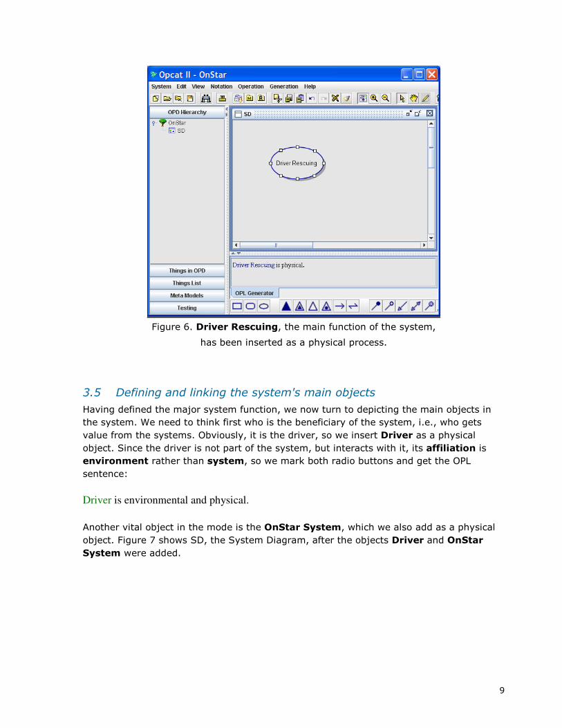
Figure 6. Driver Rescuing, the main function of the system,
has been inserted as a physical process.
3.5 Defining and linking the system's main objects
Having defined the major system function, we now turn to depicting the main objects in
the system. We need to think first who is the beneficiary of the system, i.e., who gets
value from the systems. Obviously, it is the driver, so we insert Driver as a physical
object. Since the driver is not part of the system, but interacts with it, its affiliation is
environment rather than system, so we mark both radio buttons and get the OPL
sentence:
Driver is environmental and physical.
Another vital object in the mode is the OnStar System, which we also add as a physical
object. Figure 7 shows SD, the System Diagram, after the objects Driver and OnStar
System were added.

10
Figure 7. SD after adding the two objects
As the beneficiary, Driver is affected by the Driver Rescuing process. To denote this,
click on the effect link symbol – the bidirectional arrow at the bottom right, then click on
the process and drag it from the process to the object. The result, shown in
Figure 19, is expressed in a new OPL sentence:
Driver Rescuing affects Driver.
Figure 8. SD after linking Driver and Driver Rescuing with an effect link

11
The semantics of this sentence is that the Driver's state is changed by the Driver
Rescuing process, but at this abstract level of detail, the states themselves are not
specified, so the effect link abstracts this expression. At a later stage we will describe the
relationship between the Driver and Driver Rescuing process in more details. In this
sense Effect link is a generalization of the detailed description to come.
Figure 9. Adding the four parts of OnStar System
Next, in Figure 9, the OnStar System is added as an instrument to the Driver Rescuing
process. This is done by clicking on the instrument link button – the line with the white
circle (white lollipop) – and dragging it from the OnStar System – the instrument – to
the Driver Rescuing process. The sentence added as a result is:
Driver Rescuing requires OnStar System.
Reading the OnStar description we find that " At its most basic, OnStar consists of four
different systems: cellular phone, voice recognition, GPS and vehicle telemetry."

12
We now wish to model this sentence, which describes the parts of the OnStar System.
Adding the four parts of OnStar System is shown in Figure 9.
The parts are added one by one. The location of each object is determined by where we
click on the screen after selecting the Object button.
Figure 10. Marking the four parts of OnStar System for horizontal alignment
Naturally, the objects are therefore not quite aligned, and we may wish to align them.
Marking the four parts of OnStar System for horizontal alignment is shown in
Figure 10. We mark all at once by clicking and dragging the mouse to include all the
things we wish to mark within the dotted area. The marking is shown by small white
squares on each object.
13
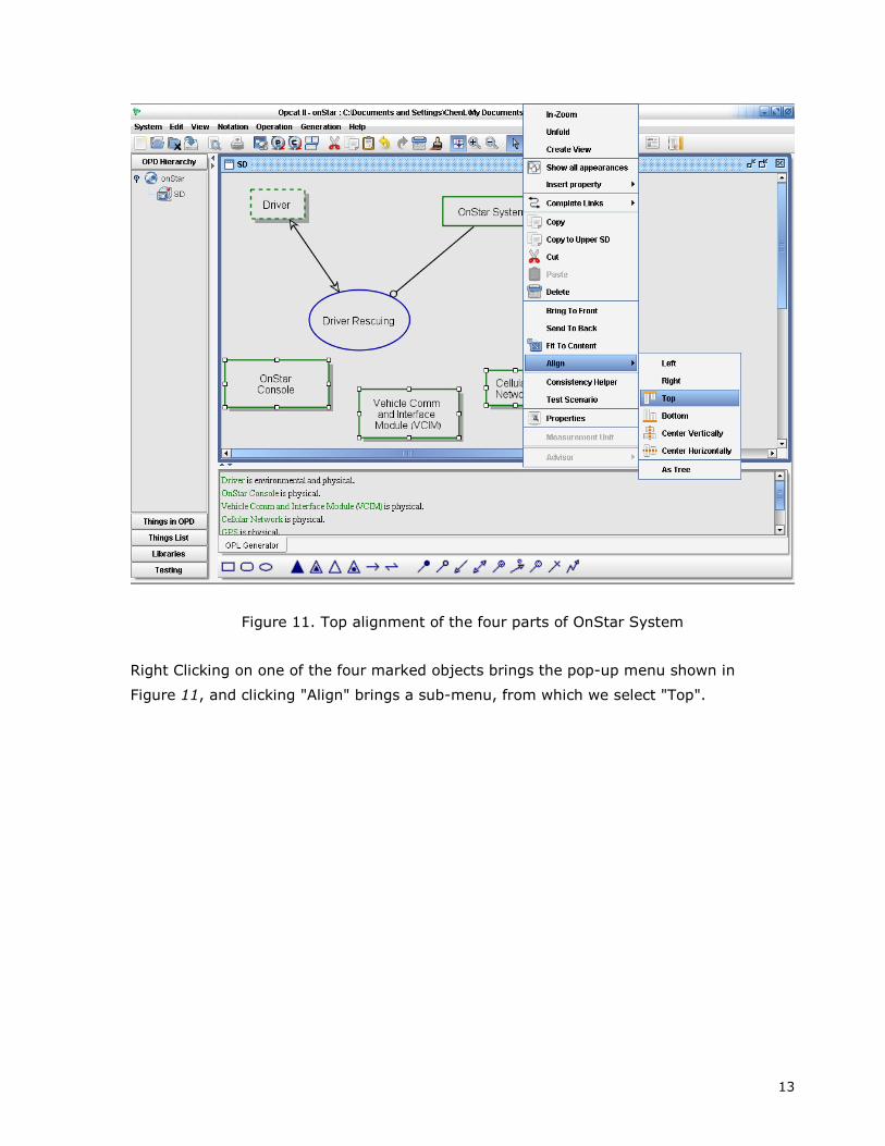
Figure 11. Top alignment of the four parts of OnStar System
Right Clicking on one of the four marked objects brings the pop-up menu shown in
Figure 11, and clicking "Align" brings a sub-menu, from which we select "Top".

14
Figure 12. The four parts of OnStar System after top alignment
The result of the aligned objects is shown in
Figure 12.
At this point, we wish to denote the fact that all these four objects are part of the OnStar
System. This is an opportunity to introduce the set of OPM symbols which appear at the
bottom of the screen.

15
3.6 Quick Summary
• The first OPD (the SD) is used to establish the main function of the system and
the objects involved in this process.
• We start off by modeling the main function of the system as the central process in
SD.
• Things (Objects or Processes) have an Essence attribute and an Affiliation
attribute.
• The default Essence is informatical and the default Affiliation is systemic.
• Things which are not informatical (such as file, command, message, algorithm)
will be marked as physical.
• Things which are not systemic – not part of the system (but interact with it) –
will be marked as environmental.
• Environmental objects interact with our system but we have no influence on their
design.
• The system can affect environmental objects but it is not responsible for creating
them.
• We add the main objects in the system, denoting, if needed, their Essence as
physical and their Affiliation as environmental.
• Each part of the system which will be modeled later is some refinement
(specification of parts, specializations, or features) of the Things in the SD.

16
4. The OPM symbols The OPM symbol buttons at the bottom of the screen are divided into three groups. The
next three figures present in tabular form each one of the three symbol groups.
3.7 Entities
The group on the left is the group of the entities: Object, state, and process.
Symbol Name:
Definition OPL
Allowed
Source-to-
Destination
connections
Semantics/ Effect
on the system
flow/ Comments
Object A:
A thing that exists
A is physical [and
environmental].
A is informatical and
systemic by default.
Things
Process B:
A thing that
transforms
(generates,
consumes, or
changes the state
of an) object.
B is physical [and
environmental].
B is informatical and
systemic by default.
State:
A situation of an
object.
A is s1.
A can be s1 or s2.
A can be s1, s2, or
s3.
Always within an
object.
Figure 13. The OPM entities

17
3.8 Structural Links
In the middle is the group of the structural links: four triangles and two arrows with open
heads.
The structural links denote static, long-term relations that have no relation to the time
dimension and hold true throughout the system's existence between an object and other
objects or between a process and other processes.
Symbol Name:
Definition OPL
Allowed
Source-to-
Destination
connections
Semantics/ Effect
on the system
flow/ Comments
Aggregation-
Participation A consist of B.
Object-Object
Process- Process Whole -Part
Exhibition-
Characterization A exhibits B.
Object-Object
Object-Process
Process-Object
Process- Process
Generalization-
Specialization
B is an A.
(objects)
B is A. (processes)
Object-Object
Process- Process
Classification-
Instantiation
B is an instance of
A.
Object-Object
Process- Process
Tagged structural
links:
Unidirectional
Bidirectional
According to text
added by user
Object-Object
Process- Process
Describes structural
information.
Figure 14. The structural links

18
3.9 Procedural Links
The OPM symbols grouped on the left are the procedural links: four triangles and two
arrows with open heads.
The procedural links denote dynamic, transient relations that have everything to do with
the time dimension. Opposite to the structural links, they connect an object and a process
but not an object to another object.
Symbol Name:
Definition OPL
Allowed
Source-to-
Destination
connections
Semantics/ Effect on the
system flow/ Comments
Agent Link A handles B.
Object (A) to
Process (B)
Denotes a human operator.
Activating the link triggers
the process B.
B requires A.
Object (A) to
Process (B)
Instrument
Link B requires s1 A.
State (s1) to
Process (B)
Wait until A is generated and
exists.
Wait until A is at state s1.
B occurs if A
exists.
Object (A) to
Process (B)
Condition
Link B occurs if A is
s1.
State (s1) to
Process (B)
Execute if object A exists,
and if not then skip process B
and continue the regular
system flow.
Execute if object A is at state
s1, and if not then skip
process B and continue the
regular system flow.
Effect Link B affects A. Object (A) to
Process (B)
Used when details of the
effect are not necessary or
will be add at a lower level
(also created when states
lined to a process with an
input-output pair are hidden-
suppressed)
Affect at an high level
signifies at lower levels –
• State changes
• Consumption and later
generation

19
Symbol Name:
Definition OPL
Allowed
Source-to-
Destination
connections
Semantics/ Effect
on the system
flow/ Comments
Consumption
Link
Result Link
Input-Output
Link Pair
B consumes A.
B yields A.
B consumes s1 A.
B yields s1 A.
B changes A from s1
to s2.
Object to Process
Process to Object
State to Process
Process to State
Process – State
s1 to Process
and Process to
s2.
Process consumes
the object.
Process creates the
object.
Process changes the
state of object.
Invocation Link B invokes C. Process-Process
Execution will proceed
if the triggering failed
(due to failure to fulfill
one or more of the
conditions in the
precondition set).
Instrument
Event Link
A triggers B.
s1 A triggers B.
Object (A) to
Process (B)
State (s1) to
Process (B)
Execution will proceed
if the triggering failed
(due to failure to fulfill
one or more of the
conditions in the
precondition set).
For normal, non-
triggered execution,
the object or state
linked is not required
for the process to take
place.
Consumption
Event Link
A triggers B, which, if
occurs, consumes A.
s1 A triggers B,
which, if occurs,
consumes A.
Object (A) to
Process (B)
State (s1) to
Process (B)
Execution will proceed
if the triggering failed
(due to failure to fulfill
one or more of the
conditions in the
precondition set).
For normal, non-
triggered execution,
the object or state
linked is not required
for the process to take
place.
Figure 15. The procedural links
20
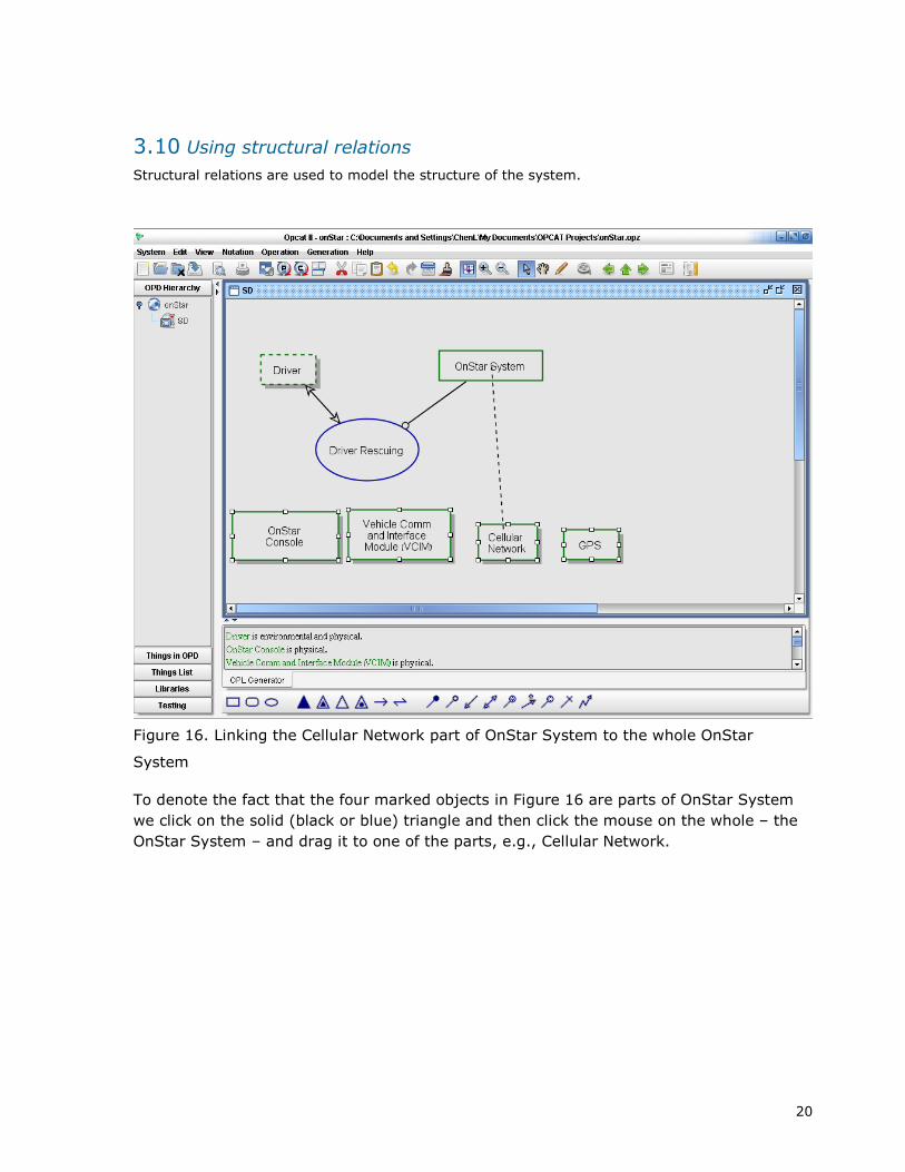
3.10 Using structural relations
Structural relations are used to model the structure of the system.
Figure 16. Linking the Cellular Network part of OnStar System to the whole OnStar
System
To denote the fact that the four marked objects in Figure 16 are parts of OnStar System
we click on the solid (black or blue) triangle and then click the mouse on the whole – the
OnStar System – and drag it to one of the parts, e.g., Cellular Network.
21
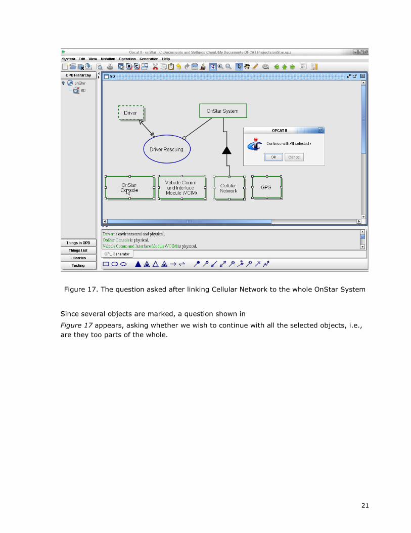
Figure 17. The question asked after linking Cellular Network to the whole OnStar System
Since several objects are marked, a question shown in
Figure 17 appears, asking whether we wish to continue with all the selected objects, i.e.,
are they too parts of the whole.

22
Figure 18. The four parts of Cellular Network are now linked to the whole OnStar System
Clicking OK will generate the four links in
Figure 18.
The resulting OPL sentence, shown in the second line of the OPL pane, is:
OnStar System consists of OnStar Console, Vehicle Comm and Interface Module (VCIM),
Cellular Network, and GPS.

23
Figure 19. Specifying that Driver communicates via OnStar Console
In order to specify that Driver communicates via OnStar Console, we click on the
unidirectional tagged structural link, the fifth button in the middle, structural links group,
and drag it from Driver to OnStar Console. The result (without the label along the link) is
shown in
Figure 19.
Inspecting the newly generated OPL sentence we see that it reads as follows:
Driver relates to OnStar Console.
Since we wish to be more specific, we double click the link we just drew and get the dialog
box in
Figure 20.

24
Figure 20. Inserting the tag "communicates via" in the unidirectional general structural relation
We type "communicates via" in the Tag box, click OK, and the OPL sentence now changes
to:
Driver communicates via OnStar Console.
This OPL sentence appears at the last line in
Figure 19.
Tagged Structural Links will be used to provide additional information about the system
that can not be expressed by using any of the other structural links.

25
5. Zooming into the main process
At this point the System Diagram, SD, is already quite crowded, but we barely scratched
the surface of specifying the OnStar System. How are we going to keep on modeling while
maintaining the OPD clear and readable?
To the rescue comes the OPM built-in in-zooming mechanism. In-zooming is a refinement
mechanism. It enables starting a new Object-process Diagram (OPD), in which a thing
(process or object) is copied from the ancestor OPD, and it is blown-up in order to enable
specifying its sub processes.
Along with the in-zoomed thing, things that were attached to it (directly or indirectly) are
brought along so as to maintain the consistency across the entire OPD set.
Figure 21. Zooming into the Driver Rescuing process
Figure 22. Zooming into the Driver Rescuing process
Right-clicking here
opens the pull-down
menu on the right.
Select In-Zoom to create
a new OPD in which
Driver Rescuing is blown-up.

26
As we seen above we first selected the main function of our system, Driver Rescuing, and
described the main necessary objects and the main result or effect of this process. Now
we will continue to refine the specification of the system using the processes as the
skeleton for decomposition.
Figure 23. The new OPD titled SD1 – Driver Rescuing in-zoomed, created after zooming
into the Driver Rescuing process
Following the "5 Plus or minus 2" law, we will continue to refine the system's specification
by adding between 3 to 6 nested subprocesses, which, in turn can be further in-zoomed
into new 3 to 6 subprocesses. We continue this until we are satisfied with the level of
detail of t he system.
SD1 should hence describe the 3 to 6 main subprocesses comprising the Driver Rescuing
process by the OnStar system.
For each process we will describe the preconditions and the result or effect. We will do this
by adding objects or states to objects, to the level of detail required i to describe the
preconditions and results of the nested subprocesses. More details about these additional
The OPD tree has been
updated with the new OPD called SD1.
SD1 is the newly created OPD.

27
objects can possibly be added when we zoom into the sub-subprocesses of each
subprocess.
Remember that OPM uses detail decomposition, i.e., the lower levels are merely a detailed
description of the upper levels. Consistency must be maintained between any two OPDs
related by a father-son relationship, so that overall the entire OPD set is consistent. For
additional explanation about this topic, please review the Advanced Course Package.
To make a call in the OnStar system, you say out-loud a phone number or a previously
stored name associated with a phone number. Modeling this statement presents us with
an opportunity to recommend an effective OPCAT design methodology.
The first subprocess of Driver Rescuing is Call Making. In Figure 24 we add this
subprocess within and at the top of the enclosing Driver Rescuing process.
Figure 24. Call Making is inserted as the first subprocess within the in-zoomed Driver
Rescuing process.
1. Click on
the process icon
2. Press inside the
Driver Rescuing to add the process

28
Call making requires the driver and the OnStar Console. In order to express this we need
to bring OnStar Console to this OPD. Since OnStar Console is already connected to the
OnStar System elsewhere we can use the Insert Property feature to facilitate this action.
Figure 25. Adding OnStar Console by using the Insert Property feature
The Insert Property feature is available if the relationship is defined in other OPD or is
inherited. It is also possible to insert structural relationship which is stated in the model
repository. To learn more about this option please refer to the Advanced Course Package.
Now its time to state that the Driver and OnStar Console are required for Call Making.

29
Figure 26. Connecting Call Making
OnStar Console is required for Call Making and therefore connected with an Instrument
Link. Driver is also required for Call Making but is connected with Agent link. The Agent
link denotes that Driver is a human required for the Call Making process.
Now we need to ask ourselves what is the result or effect of Call Making. In this case the
result is a call.
30
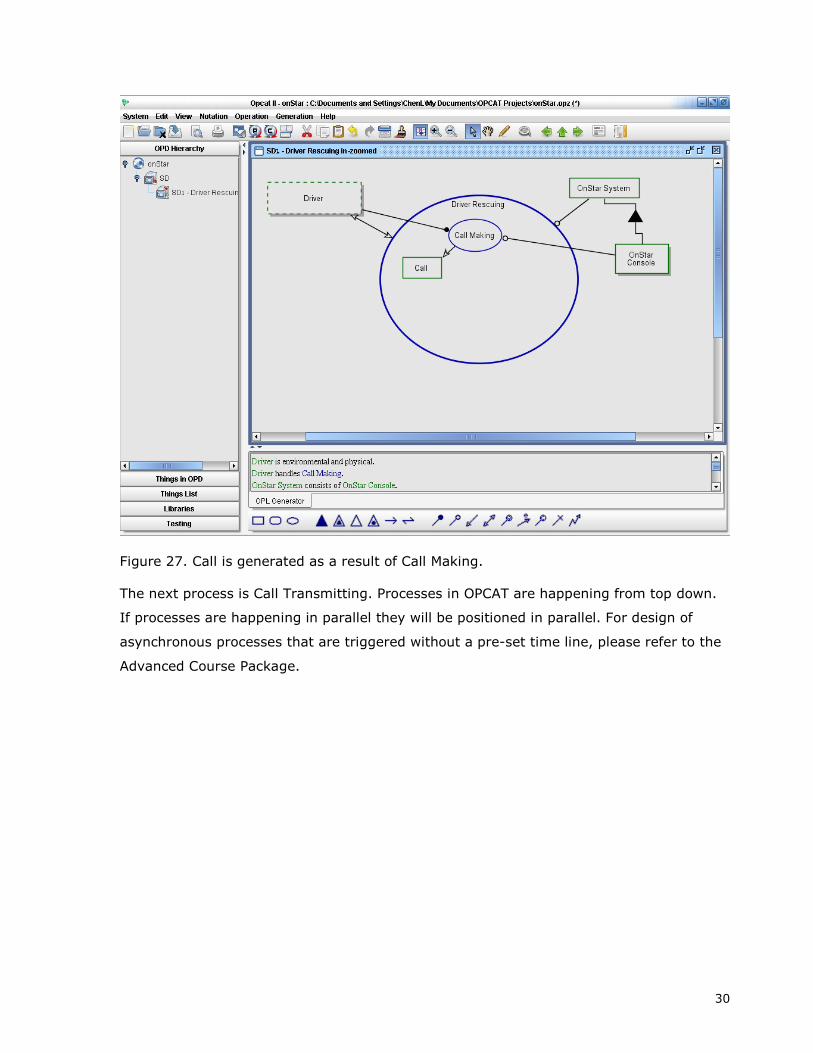
Figure 27. Call is generated as a result of Call Making.
The next process is Call Transmitting. Processes in OPCAT are happening from top down.
If processes are happening in parallel they will be positioned in parallel. For design of
asynchronous processes that are triggered without a pre-set time line, please refer to the
Advanced Course Package.

31
Figure 28. Call Transmitting preconditions
Call Transmitting is using the Cellular Network and affecting the Call. In order to add
Cellular Network to SD1 we can use the Insert Property feature or cut & paste it from
other OPD.
In Parallel the Vehicle Location Calculating is using the GPS to produce the Vehicle
Location

32
Figure 29. Adding Vehicle Location Calculating
Quick Summary
• We in-zoom into the main process and then describe the different sub-
process
• The process activation order is from top down. Parallel processes will be
positioned in parallel.
• Processes without a time line will be positioned outside the process. For
more information about this please refer to the OPCAT Advanced Course
lessons.
• In parallel we will describe the surrounding objects. Each process will be
connected to the relevant process. Objects that are needed for all the
internal processes can be connected with one link to the in zoomed process.

33
6. Basic Conditional Flow As explained previously the Effect link between Call Transmitting and Call might be
replaced in lowers OPD by a more detailed links. If we have decided to detail the type of
the effect at this level the OPD may look like this:
Figure 30. Detailing Call states
Figure 30 shows how we can add states to Call and detailing the fact that Call
Transmitting is changing Call from requested to online. This fact is also represented by the
OPL.
Figure 31 express an alternative design in which Vehicle Location Calculating is occurring
only when Call is online. Note the difference in the source of the instrument link between
Figure 30 and 31.
Figure 31. Conditional flow
Additional information about conditional flow can be found in the Advance Course
Package.

34
Figure 322. Conditional flow
35
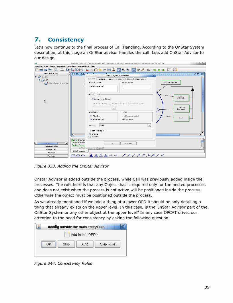
7. Consistency Let’s now continue to the final process of Call Handling. According to the OnStar System
description, at this stage an OnStar advisor handles the call. Lets add OnStar Advisor to
our design.
Figure 333. Adding the OnStar Advisor
Onstar Advisor is added outside the process, while Call was previously added inside the
processes. The rule here is that any Object that is required only for the nested processes
and does not exist when the process is not active will be positioned inside the process.
Otherwise the object must be positioned outside the process.
As we already mentioned if we add a thing at a lower OPD it should be only detailing a
thing that already exists on the upper level. In this case, is the OnStar Advisor part of the
OnStar System or any other object at the upper level? In any case OPCAT drives our
attention to the need for consistency by asking the following question:
Figure 344. Consistency Rules

36
Selecting OK will add OnStar Advisor to the top OPD. Another question is whether the
OnStar Advisor is part of the system. If not, we will mark the OnStar Advisor as
Environmental.
Figure 355. OnStar Advisor Properties
We will now connect the OnStar Advisor with an Agent Link. At SD the OnStar Advisor will
be connected to the Driver Rescuing Process. At SD1 we will detail to which specific
process the Onstar Advisor is required and therefore connect the Agent link to Call
Handling process.
In addition, in order for call handling to happen we need the Driver, the Vehicle Location.
Figure 36. Call Handling Preconditions

37
Eventually, the Call Handling Process is changing the Drivers Danger Status from in
danger to safe. Danger Status is and attribute of the Driver.
Figure 37. Call Handling results

38
8. Marking Initial States
At this stage we may want to emphasis the fact that when the system starts to operate
the Danger Status is in the state endangered. We may also want to say that the object
call is created by the process Call Making in the state of requested. We can do this by
marking those states as “initial”.
Figure 38. Marking initial states
Right click on
the state and
mark as initial

39
9. In-zooming into the next level
At this stage when our Driver is finally safe we can continue and go into the details of
each of the sub-processes.
When in-zooming into more details we must remember that each OPD draw the borders
for the lower OPDs. For instance Call Making is using OnStar Console and the Driver and
yields a Call. At the next level we might describe the different parts of the OnStar Console,
user interface, authentication processes and so on. Nevertheless, it will all be details of
the Driver, Call Making or OnStar Console. If we have found that something is missing
then it should be added to the upper OPD as well, as demonstrated above with regard to
the OnStar Advisor. If you go back to the requirements described at the beginning of this
guide you will see that there is a possibility of automatic Call Making by using a “small
panel located in the rearview mirror”. If this panel is part of the OnStar Console it will be
described at the next level. If not it should be added to SD1 and marked as instrument to
Call Making.
Figure 398. returning to top level OPD
It may be also a good time to revisit the upper OPD and decide whether we need this level
of details at the top level. We may decide for example that the parts of the OnStar
System will be described only at the lower levels.
40
10. Summary
This guide is providing you the basic concepts of OPM design. You are more than welcome
to complete the design of the OnStar System according to the requirements stated at the
beginning of this Guide.
In order to learn how to use the simulation, tagging, views creation, model repository and
additional advanced topics you are invited to obtain the OPCAT Advanced Course Package
by contacting us at [email protected].

41
List of Diagrams Figure 2. A blank OPCAT opening screen .................................................................................. 5 Figure 3. The New System Properties dialog box ....................................................................... 6 Figure 4. OPCAT Screen after opening the new OnStar System model.......................................... 7 Figure 5. The Process Properties dialog box .............................................................................. 8 Figure 6. Driver Rescuing, the main function of the system,..................................................... 9 Figure 7. SD after adding the two objects............................................................................... 10 Figure 8. SD after linking Driver and Driver Rescuing with an effect link ................................. 10 Figure 9. Adding the four parts of OnStar System.................................................................... 11 Figure 10. Marking the four parts of OnStar System for horizontal alignment .............................. 12 Figure 11. Top alignment of the four parts of OnStar System.................................................... 13 Figure 12. The four parts of OnStar System after top alignment ................................................ 14 Figure 13. The OPM entities .................................................................................................. 16 Figure 14. The structural links............................................................................................... 17 Figure 15. The procedural links ............................................................................................. 19 Figure 16. Linking the Cellular Network part of OnStar System to the whole OnStar System ......... 20 Figure 17. The question asked after linking Cellular Network to the whole OnStar System ............ 21 Figure 18. The four parts of Cellular Network are now linked to the whole OnStar System ............ 22 Figure 19. Specifying that Driver communicates via OnStar Console .......................................... 23 Figure 20. Inserting the tag "communicates via" in the unidirectional general structural relation ... 24 Figure 21. Zooming into the Driver Rescuing process ............................................................... 25 Figure 22. Zooming into the Driver Rescuing process ............................................................... 25 Figure 23. The new OPD titled SD1 – Driver Rescuing in-zoomed, created after zooming into the
Driver Rescuing process ....................................................................................................... 26 Figure 24. Call Making is inserted as the first subprocess within the in-zoomed Driver Rescuing
process. ............................................................................................................................. 27 Figure 25. Adding OnStar Console by using the Insert Property feature...................................... 28 Figure 26. Connecting Call Making ......................................................................................... 29 Figure 27. Call is generated as a result of Call Making.............................................................. 30 Figure 28. Call Transmitting preconditions .............................................................................. 31 Figure 29. Adding Vehicle Location Calculating ........................................................................ 32 Figure 30. Detailing Call states.............................................................................................. 33 Figure 31. Conditional flow ................................................................................................... 33 Figure 322. Conditional flow.................................................................................................. 34 Figure 333. Adding the OnStar Advisor................................................................................... 35 Figure 344. Consistency Rules............................................................................................... 35 Figure 355. OnStar Advisor Properties.................................................................................... 36 Figure 36. Call Handling Preconditions.................................................................................... 36 Figure 37. Call Handling results ............................................................................................. 37 Figure 38. Marking initial states............................................................................................ 38 Figure 398. returning to top level OPD ................................................................................... 39

42
Annex A
OnStar System Specification
Being in a car accident, you push a button on a console and are instantly connected with
an OnStar advisor. The advisor can pinpoint your exact location and relay your problem to
emergency services. If you're in an accident, your car can "tell" OnStar without you
having to do a thing.
Source: http://auto.howstuffworks.com/onstar.htm/printable
Cars equipped with OnStar have a small panel located in the rearview mirror, the
dashboard or an overhead console, depending on the model. The blue OnStar button
allows you to contact a live or virtual advisor. The red button with the cross on it is for
emergencies, and the phone or "white dot"
button allows you to make phone calls just as if
you were using a cell phone.
At its most basic, OnStar consists of four
different systems: cellular phone, voice
recognition, GPS and vehicle telemetry. All of
the services that OnStar provides are a result
of one or more of these systems working
together, making it a ""System of Systems".
OnStar's cellular service is voice-activated and
hands-free. The console contains a built-in
microphone and uses the car speakers. To
make a call, you speak a phone number or a
previously stored name associated with a phone number. The console is connected to a
Vehicle Comm and Interface Module (VCIM), which uses a cellular antenna on top of the
car to transmit signals to OnStar's cellular network.
For calls to the advisor, OnStar uses voice recognition software. OnStar can "surf the
Web" using the Virtual Advisor automated system. For this service, OnStar uses text-to-
voice technology called VoiceXML. When you ask for information, such as "weather," the
software translates your request into XML (Extensible Markup Language) and matches it
to settings in your OnStar profile. Then it translates the information into VoiceXML and
reads it to you.
The GPS receiver is called OnCore, and it is part of the VCIM. A GPS receiver in the vehicle
picks up signals form GPS satellites and calculates the location of the vehicle. The OnStar
Call Center uses four different satellites to pinpoint the car's location when either the
driver or the car itself asks to be located. That location is stored in the vehicle's OnStar
hardware. The GPS uses the amount of time that it takes for a radio signal to get from
satellites to a specific location to calculate distance.
When the driver pushes the blue OnStar button or red emergency button or an airbag
deploys, OnStar places an embedded cellular call the OnStar Center with the vehicle
location data. An OnStar advisor handles the call.

43
To give a vehicle the ability to call when it is in an accident, OnStar uses an event data
recorder (also known as a crash data recorder). GM calls the entire process the Advanced
Automatic Crash Notification System (AACN). The AACN system comprises four
components: sensors, the Sensing Diagnostic Module (which includes the event data
recorder), the VCIM and the cellular antenna. When the car is in a crash, sensors transmit
information to the Sensing Diagnostic Module (SDM). The SDM also includes an
accelerometer, which measures the severity of the crash based on gravitational force. The
SDM sends this information to the VCIM, which uses the cellular antenna to send a
message to the OnStar Call Center. When an advisor receives the call, he uses the GPS to
find the vehicle's location and calls the car to check with the driver. Even if there's not a
measurable impact, the VCIM also sends a message when the air bag goes off, prompting
the advisor to call the car's driver.