ontological assembly representation of a reduction gearbox...
TRANSCRIPT

Ontological Assembly Representation of
a Reduction Gearbox by use of Protégé OWL Kang Li
In the broad field of Product Development, Product Lifecycle Management (PLM) is of great importance to the design and manufacturing part throughout the whole process. The development of ontological assembly representation was initiated from several considerations concerning assembly representation for PLM. Ontological representation, due to its inherent advantages, can help achieve high interoperability level that enables efficient implementation of PLM and identify a common data structure to allow data exchange between platforms. There are several kinds of software that is able to perform ontology-based modeling and analysis, and Protégé is a commonly used and powerful tool in this area. To make this idea more clear, this report will choose a typical assembly case, namely a reduction gearbox, build the corresponding ontology and explore the ontology assembly model by using related plug-ins.
1. Introduction
1.1 Ontology
This project presupposes prior knowledge regarding the term “ontology”; this word was generally used in a philosophical context in old times, but in recently years it has become a sub-discipline under Artificial Intelligence and Information science. We might wonder: why do we develop Ontology in the first place? Some of the reasons are:
• To share common understanding of information structure among people or software agents
• To enable reuse of domain knowledge
• To make domain assumptions explicit
• To separate domain knowledge from the operational knowledge
• To analyze domain knowledge
Sharing common understanding of information structure among people or software agents is one of the more common goals in developing ontologies. Enabling reuse of domain knowledge was one of the driving forces behind recent surge in ontology research. Making explicit domain assumptions underlying an implementation makes it possible to change these assumptions easily if our knowledge about the domain changes. Separating the domain knowledge from the operational knowledge is another common use of ontologies. We can describe a task of configuring a product from its components according to a required specification and implement a program that does this configuration independent of the products and components themselves. Analyzing domain knowledge is possible once a declarative specification of the terms is available. Formal analysis of

terms is extremely valuable when both attempting to reuse existing ontologies and extending them. Often an ontology of the domain is not a goal in itself. Developing an ontology is akin to defining a set of data and their structure for other programs to use.
Having a basic understanding on the usefulness of ontology, we may need to clearly and formally define ontology . The Artificial-Intelligence literature contains many definitions of an ontology; many of these contradict one another. For the purposes of this report an ontology is a formal explicit description of concepts in a domain of discourse (classes, sometimes called concepts), properties of each concept describing various features and attributes of the concept, and restrictions on properties (sometimes called role restrictions). An ontology together with a set of individuals of classes constitutes a knowledge base.
1.2 Protégé and Protégé-OWL
Protégé is a free, open-source platform that provides a growing user community with a suite of tools to construct domain models and knowledge-based applications with ontologies. At its core, Protégé implements a rich set of knowledge-modeling structures and actions that support the creation, visualization, and manipulation of ontologies in various representation formats. Protégé can be customized to provide domain-friendly support for creating knowledge models and entering data. Further, Protégé can be extended by way of a plug-in architecture and a Java-based Application Programming Interface (API) for building knowledge-based tools and applications.
An ontology describes the concepts and relationships that are important in a particular domain, providing a vocabulary for that domain as well as a computerized specification of the meaning of terms used in the vocabulary. Ontologies range from taxonomies and classifications, database schemas, to fully axiomatized theories. In recent years, ontologies have been adopted in many business and scientific communities as a way to share, reuse and process domain knowledge. Ontologies are now central to many applications such as scientific knowledge portals, information management and integration systems, electronic commerce, and semantic web services.
The Protégé platform supports two main ways of modeling ontologies: Protégé-Frames and Protégé-OWL editors. The Protégé-Frames editor enables users to build and populate ontologies that are frame-based, in accordance with the Open Knowledge Base Connectivity protocol (OKBC). In this model, an ontology consists of a set of classes organized in a subsumption hierarchy to represent a domain's salient concepts, a set of slots associated to classes to describe their properties and relationships, and a set of instances of those classes - individual exemplars of the concepts that hold specific values for their properties. The Protégé-OWL editor enables users to build ontologies for the Semantic Web, in particular in the W3C's Web Ontology Language (OWL). "An OWL ontology may include descriptions of classes, properties and their instances. Given such an ontology, the OWL formal semantics specifies how to derive its logical consequences, i.e. facts not literally present in the ontology, but entailed by the semantics. These entailments may be based on a single document or multiple distributed documents that have been combined using defined OWL mechanism. Protégé-OWL can be regarded as an extension of Protégé that supports Web Ontology Language.
OWL ontologies may be categorised into three species or sub-languages: OWL-Lite, OWL-DL and OWL-Full. A defining feature of each sub-language is its expressiveness. OWL-Lite is the least

expressive sub-langauge. OWL-Full is the most expressive sub-language. The expressiveness of OWL-DL falls between that of OWL-Lite and OWL-Full. OWL-DL may be considered as an extension of OWL-Lite and OWL-Full an extension of OWL-DL. OWL-DL is much more expressive than OWL-Lite and is based on Description Logics. Description Logics are a decidable fragment of First Order Logic and are therefore amenable to automated reasoning. It is therefore possible to automatically compute the classification hierarchy and check for inconsistencies in an ontology that conforms to OWL-DL. This report will employ OWL-DL to implement the specific assembly, and use the lastest versatile version of Protégé 3.4 Beta to experience with the features and characteristics of ontological assembly model.
OWL ontologies have three components: Individuals, Properties and Classes, Figure 1 is a screen shot of an OWL ontology. We will elaborate on how to work with it later.
Figure 1 Protégé-OWL user interface window
2 Assembly Description
The Reduction Gearbox System is an electromechanical component usually used to change the rotational speed or the torque of a shaft. In this specific case, our goal is to represent a scenario of an assembly representation to outline assembly complexity but at the same time not to complicate the example itself; with this in mind, some structure and relationship between different parts have been simplified or modified in a reasonable way.
2.1 Components in Reduction Gearbox System

The system consists of 2 subassemblies with 14 parts. The solid model of the reduction gearbox system is built in Pro/Engineer Wildfire 4.0 as is shown Figure 2.
Figure 2 Reduction Gearbox System
The Reduction Gearbox System consists of several components. Figure 3 shows the exploded view of the above solid model. The list of all the components of the gear box system is given in Table 1.
Figure 3 Exploded view of the Reduction Gearbox System

ID Name Quantity Functional Description
1 Lower Housing 1 Cover, support and protect shafts and gears
2 Upper Housing 1 Cover, support and protect shafts and gears
3 Input Shaft 1 Input and transmit power
4 Input Bearing 2 Support the rotation of input shaft
5 Output Shaft 1 Output power
6 Output Gear 1 Transmit power
7 Output Bearing 2 Support the rotation of output shaft
8 Output Key 1 Transmit power from output gear to output shaft
9 Screw 4 Connect lower and upper housing
Table 1 Components of the Reduction Gearbox System
2.2 Assembly Hierarchy
Figure 4 Reduction Gearbox System Structure
It’s necessary to define assembly hierarchy for the reduction gearbox system, which is composed of three parts and two sub-assemblies as in Figure 4. The parts include lower housing, upper housing and four screws. The two sub-assemblies include: (1) the input end assembly comprising a gear shaft and two bearings; (2) the output end assembly comprising a shaft, a gear, two bearings and a key.

Figure 5 Reduction Gearbox Hierarchy
The hierarchical relationships between the components of the gearbox system can be represented as an instance diagram as shown in Figure 5. The names take the form of “instance name: class name”, which will make it easier to implement this particular assembly ontology in subsequent operations within Protégé-OWL environment. The root node is the entire assembly; the interior nodes are sub-assemblies, and the leaf nodes are component parts.
Figure 6 Connection between parts
ReductionGearboxAsm: Assembly
LowerHousing: Part
InputAxialAsm: Assembly
Screws: Part
UpperHousing: Part
OutputAxialAsm: Assembly
InputBearing1: Part
InputBearing2: Part
InputShaft: Part
OutputBearing1: Part
OutputBearing2: Part
OutputShaft: Part
OutputGear: Part
OutputKey: Part

The connections between parts are presented in Figure 6. The naming conventions are related to the types of possible connections (fc: fixed connection, mc: movable connection). These connections between parts are represented in the model through instances of the class ArtifactAssociation.
2.3 Case Implementation
In this section, the use case implementation is presented. For explanation of the Reduction Gearbox System example, the structure of the ontology will be followed and every class will be presented twice with its Individuals and Properties. Accordingly, this section is divided into two main parts: Input Individuals and Output Individuals.
2.3.1 Asserted Individuals and Properties
Before we actually build the ontology in Protégé 3.4 Beta OWL package, it is advisable to work out the frame of the whole model, namely, which classes, subclasses, properties and individuals we wish to put into the final OWL-ontology. Name of classes will be in bold type, properties in shadow and individuals in italic.
2.3.1.1 Asserted Artifact Individuals and properties
The class Artifact has three subclasses: Assembly, Meaningless_Artifact, and Part. The reasoning capabilities of the model allow us to create all the instances of Assembly directly as Artifacts and then infer them as individuals of Assembly. This is possible defining an Assembly as an Artifact composed by at least two subassemblies (through restriction on the property artifactHasPart_direct)
Asserted Properties Artifact Individuals artifactHasPart_direct partofArtifact_direct
Input_Axial_Assembly
Input_Bearing_1 Input_Bearing_2
Input_Shaft Input_Axial_Assembly*
Reduction_Gearbox_Assembly
Output_Axial_Assembly
Output_Bearing_1 Output_Bearing_2
Output_Shaft Output_Gear Output_Key
Reduction_Gearbox_Assembly
Reduction_Gearbox_Assembly
Input_Axial_Assembly Output_Axial_Assembly
Lower_Housing Upper_Housing
Screw_1 Screw_2 Screw_3 Screw_4
--
Table 2 Artifact: asserted individuals and properties
The input individuals of the class Artifact are presented in Table 2. In the first column of the table are

the individuals of artifact. In other columns, are the individuals of the related classes linked through the properties that names these columns. From the table, notice that the Input_Axial_Assembly is incorrectly defined i.e., composed by itself (*). This error is purposely introduced for testing the reasoning capabilities.
2.3.1.2 Asserted Assembly Individuals and properties
It is possible to assert all individuals of the class Assembly as individuals of the class Artifact and let the reasoner (in this case the Racer) reclassify the individuals. At this point the class Assembly is empty.
2.3.1.3 Asserted Meaningless_Artifact Individuals and properties
This class is created for managing the impossibility of blocking the creation of a self-reference in the current version of Protégé-OWL. In the current model it is possible to define an individual of Assembly composed by itself. Presently, there is no direct solution and hence the class “Meaningless_Artifact” is created. For demonstration purposes the wrong definition of Input_Axial_Assembly the in introduced for testing the capability of the ontology to identify this kind of error.
2.3.1.4 Asserted Part Individuals and Properties
Although the class Part in a subclass of the classs Artfact, it is impossible to assert that individuals of the different parts as individuals of Artifact and later infer them as individuals of Part as with the case of the individuals of Assembly. This is due to the limitation with OWL: we cannot define a class as a class without a property. An individual of Part is an Artifact that is not composed by any other Parts but for a reasoner an Artifact without a property (artifactHasPart_direct) is not an individual of Part but only an individual not yet completely defined. For this reason all the parts are created direcdtly in the class Part. The asserted individuals and properties for the class Part are shown in Table 3.
Asserted Properties Part Individuals partOfArtifact_direct artifatHasFeature part2ArtifactAssociation
Input_Bearing-1 Input_axial_Assembly Input_Inner_Race_1 mc_2 Input_Outer_Race_1 fc_2
Input_Bearing-2 Input_axial_Assembly Input-Inner_Race-2 mc_2 Input-Outer_Race-2 fc_3
Input_Shaft
Input_axial_Assembly
Input_Bearing_Seat_1 mc_2 Input_Bearing_Seat_2 mc_2
Input_Gear_Teeth mc_1
Output_Bearing-1 Output_axial_Assembly Output_Inner_Race_1 mc_3 Output_Outer_Race_1 fc_4
Output_Bearing-2 Output_axial_Assembly Output_Inner_Race_2 mc_3 Output_Outer_Race_2 fc_5
Output_Shaft
Output_axial_Assembly
Output_Bearing_Seat_1 mc_3 Output_Bearing_Seat_2 mc_3
Output_Key_Side_1 fc_6
Output_Gear Output_axial_Assembly Output_Key_Side_2 fc_7 Output_Gear_Teeth mc_1

Output_Key Output_axial_Assembly Output_Shaft_Side fc_6 Output_Gear_Side fc_7
Lower_Housing
Redcution_Gearbox_Assembly
Input_Bearing_Seat_3 fc_2 Input_Bearing_Seat_4 fc_3
Output_Bearing_Seat_3 fc_4 Output_Bearing_Seat_4 fc_5
Threaded_Hole_1 fc_1 Threaded_Hole_2 fc_1 Threaded_Hole_3 fc_1 Threaded_Hole_4 fc_1
Upper_Housing
Redcution_Gearbox_Assembly
Thru_Hole_1 fc_1 Thru_Hole_2 fc_1 Thru_Hole_3 fc_1 Thru_Hole_4 fc_1
Screw_1 Redcution_Gearbox_Assembly Thread_1 fc_1 Screw_2 Redcution_Gearbox_Assembly Thread_2 fc_1 Screw_3 Redcution_Gearbox_Assembly Thread_3 fc_1 Screw_4 Redcution_Gearbox_Assembly Thread_4 fc_1
Table 3 Asserted individuals and properties
2.3.1.5 Asserted Feature Individuals and Properties
The class Feature has the same level of the class Artifact and stores the individuals that represent the features of the single parts. Table 4 presents the individuals of the class Feature that participate in the creation of the assemblies through the different types of connections. AFA stands for Assembly Feature Association and AFAR Assembly Feature Association Representation.
Asserted Feature Individuals & Properties Feature featureOfArtifact feature2AFA feature2AFAR
Input_Inner_Race_1 Input_Bearing-1
AFA_mc_2 AFAR_mc_2 Input_Outer_Race_1 AFA_fc_2 AFAR_fc_2 Input_Inner_Race-2
Input_Bearing-2 AFA_mc_2 AFAR_mc_2
Input_Outer_Race-2 AFA_fc_3 AFAR_fc_3 Input_Bearing_Seat_1
Input_Shaft AFA_mc_2 AFAR_mc_2
Input_Bearing_Seat_2 AFA_mc_2 AFAR_mc_2 Input_Gear_Teeth AFA_mc_1 AFAR_mc_1
Output_Inner_Race_1 Output_Bearing-1
AFA_mc_3 AFAR_mc_3 Output_Outer_Race_1 AFA_fc_4 AFAR_fc_4 Output_Inner_Race_2
Output_Bearing-2 AFA_mc_3 AFAR_mc_3
Output_Outer_Race_2 AFA_fc_5 AFAR_fc_5 Output_Bearing_Seat_1
Output_Shaft AFA_mc_3 AFAR_mc_3
Output_Bearing_Seat_2 AFA_mc_3 AFAR_mc_3 Output_Key_Side_1 AFA_fc_6 AFAR_fc_6 Output_Key_Side_2
Output_Gear AFA_fc_7 AFAR_fc_7
Output_Gear_Teeth AFA_mc_1 AFAR_mc_1
Output_Shaft_Side Output_Key
AFA_fc_6 AFAR_fc_6 Output_Gear_Side AFA_fc_7 AFAR_fc_7
Input_Bearing_Seat_3
Lower_Housing
AFA_fc_2 AFAR_fc_2 Input_Bearing_Seat_4 AFA_fc_3 AFAR_fc_3
Output_Bearing_Seat_3 AFA_fc_4 AFAR_fc_4 Output_Bearing_Seat_4 AFA_fc_5 AFAR_fc_5
Threaded_Hole_1 AFA_fc_1 AFAR_fc_1 Threaded_Hole_2 AFA_fc_1 AFAR_fc_1 Threaded_Hole_3 AFA_fc_1 AFAR_fc_1 Threaded_Hole_4 AFA_fc_1 AFAR_fc_1
Thru_Hole_1
Upper_Housing
AFA_fc_1 AFAR_fc_1 Thru_Hole_2 AFA_fc_1 AFAR_fc_1 Thru_Hole_3 AFA_fc_1 AFAR_fc_1 Thru_Hole_4 AFA_fc_1 AFAR_fc_1
Thread_1 Screw_1 Screw_2 Screw_3 Screw_4
AFA_fc_1 AFAR_fc_1 Thread_2 AFA_fc_1 AFAR_fc_1 Thread_3 AFA_fc_1 AFAR_fc_1 Thread_4 AFA_fc_1 AFAR_fc_1
Table 4 Features: asserted individuals
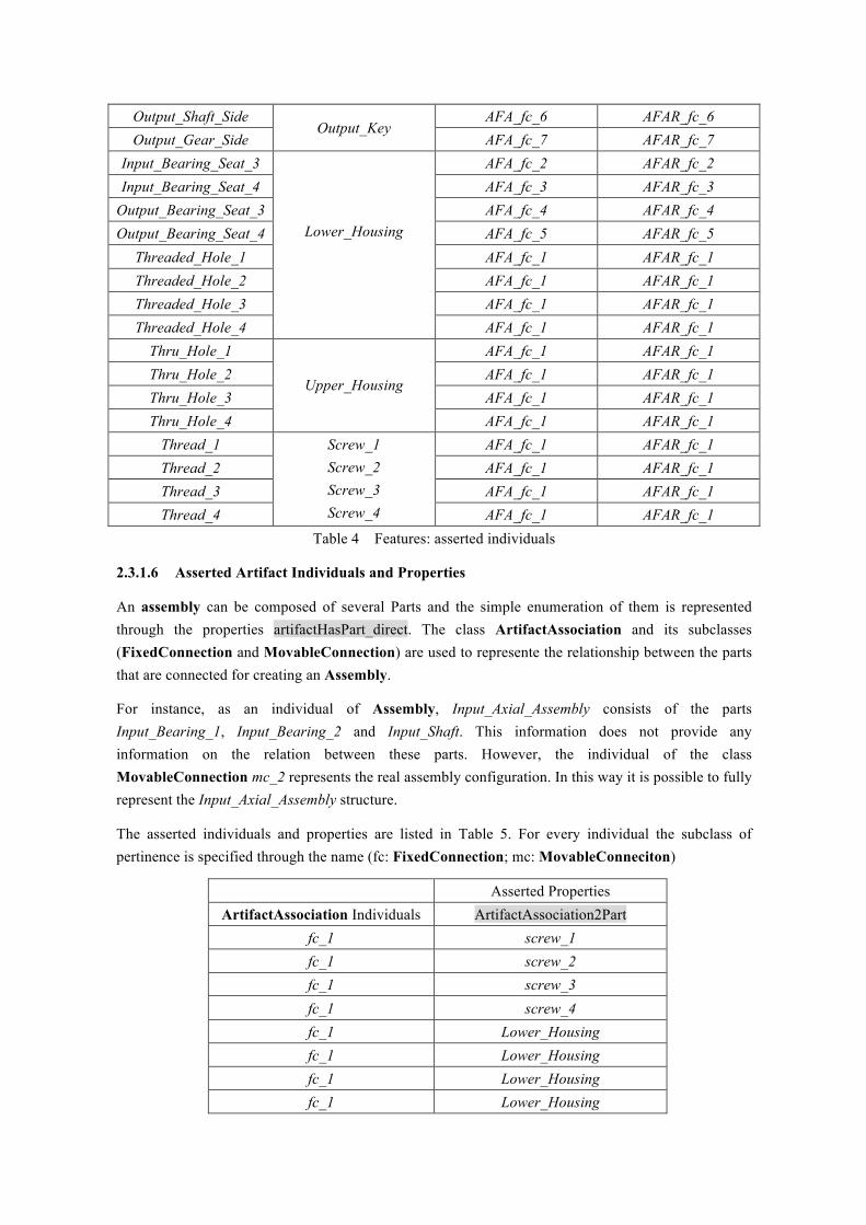
2.3.1.6 Asserted Artifact Individuals and Properties
An assembly can be composed of several Parts and the simple enumeration of them is represented through the properties artifactHasPart_direct. The class ArtifactAssociation and its subclasses (FixedConnection and MovableConnection) are used to represente the relationship between the parts that are connected for creating an Assembly.
For instance, as an individual of Assembly, Input_Axial_Assembly consists of the parts Input_Bearing_1, Input_Bearing_2 and Input_Shaft. This information does not provide any information on the relation between these parts. However, the individual of the class MovableConnection mc_2 represents the real assembly configuration. In this way it is possible to fully represent the Input_Axial_Assembly structure.
The asserted individuals and properties are listed in Table 5. For every individual the subclass of pertinence is specified through the name (fc: FixedConnection; mc: MovableConneciton)
Asserted Properties ArtifactAssociation Individuals ArtifactAssociation2Part
fc_1 screw_1 fc_1 screw_2 fc_1 screw_3 fc_1 screw_4 fc_1 Lower_Housing fc_1 Lower_Housing fc_1 Lower_Housing fc_1 Lower_Housing

fc_1 Upper_Housing fc_1 Upper_Housing fc_1 Upper_Housing fc_1 Upper_Housing fc_2 Input_Bearing_1 fc_2 Lower_Housing fc_3 Input_Bearing_2 fc_3 Lower_Housing fc_4 Output_Bearing_1 fc_4 Lower_Housing fc_5 Output_Bearing_2 fc_5 Lower_Housing fc_6 Output_Key fc_6 Output_Shaft fc_7 Output_Gear fc_7 Output_Key mc_1 Input_Shaft mc_1 Output_Gear mc_2 Input_Shaft mc_2 Input_Bearing_1 mc_2 Input_Shaft mc_2 Input_Bearing_2 mc_3 Output_Shaft mc_3 Output_Bearing_1 mc_3 Output_Shaft mc_3 Output_Bearing_2
Table 5 ArtifactAssociation: asserted individuals and properties
2.3.1.7 Asserted AssemblyFeatureAssociation Individuals and Properties
Asserted Properties AFA Individuals AFA2AFAR AFA2Feature
AFA_fc_1
AFAR_fc_1
Threaded_Hole_1 Threaded_Hole_2 Threaded_Hole_3 Threaded_Hole_4
Thru_Hole_1 Thru_Hole_2 Thru_Hole_3 Thru_Hole_4
Thread_1 Thread_2 Thread_3 Thread_4

AFA_fc_2 AFAR_fc_2 Input_Outer_Race_1
Input_Bearing_Seat_3
AFA_fc_3 AFAR_fc_3 Input_Outer_Race-2
Input_Bearing_Seat_4
AFA_fc_4 AFAR_fc_4 Output_Outer_Race_1
Output_Bearing_Seat_3
AFA_fc_5 AFAR_fc_5 Output_Outer_Race_2
Output_Bearing_Seat_4
AFA_fc_6 AFAR_fc_6 Output_Key_Side_1 Output_Shaft_Side
AFA_fc_7 AFAR_fc_7 Output_Key_Side_2 Output_Gear_Side
AFA_mc_1 AFAR_mc_1 Input_Gear-Teeth
Output_Gear-Teeth
AFA_mc_2
AFAR_mc_2
Input_Inner_Race_1 Input_Inner_Race_2
Input_Bearing_Seat_1 Input_Bearing_Seat_2
AFA_mc_3
AFAR_mc_3
Output_Inner_Race_1 Output_Inner_Race_2
Output_Bearing_Seat_1 Output_Bearing_Seat_2
Table 6 AssemblyFeatureAssociation: asserted individuals and properties
The AssemblyFeatureAssociation class has the same aim of ArtifactAssociation but at the feature level. If two parts are connected through an individual of ArtifactAssociation then two Features of these parts have to be connected through an individual of AssemblyFeatureAssociation. This class has two properties AFA2Feature and AFA2AFAR. The property AFA2Feature has the similar function as ArtifactAssociation2Part and links at least two Features realizing an assembly constituted of two parts. The property AFA2AFAR links the individuals of AssemblyFeatureAssociation with AssemblyFeatureAssociationRepresentation. The AssemblyFeatureAssociationRepresentation class is used to connect the Feature with several classes used in tolerances and geometric representations. The asserted individuals and properties are shown in Table 6.
2.3.1.8 Asserted AssemblyFeatureAssociationRepresentation Individuals and Properties
Asserted Properties Asserted Properties AFAR individuals AFAR2AFA AFAR individuals AFAR2AFA
AFAR_fc_1 AFA_fc_1 AFAR_fc_6 AFA_fc_6 AFAR_fc_2 AFA_fc_2 AFAR_fc_7 AFA_fc_7 AFAR_fc_3 AFA_fc_3 AFAR_mc_1 AFA_mc_1 AFAR_fc_4 AFA_fc_4 AFAR_mc_2 AFA_mc_2 AFAR_fc_5 AFA_fc_5 AFAR_mc_3 AFA_mc_3 Table 7 AssemblyFeatureAssociationRepresentation: asserted individuals and properties

2.3.2 Protégé-OWL Implementation
After all the preparatory work done in the previous section, it is now quite convenient and clear to assert required classes, properties and individuals with Protégé.
Open Protégé 3.4 Beta, Create New Project and choose OWL/RDF Files option. Save the project as “ReductionGearbox.owl”.
2.3.2.1 Create Classes Hierarchy
Click on the orange OWL Classes tab to shift focus on the classes definition. In the SUBCLASS EXPLORER pane to the left side, click on “create subclass” to create class Artifact. Notice the first class is created as a subclass of the root class owl:Thing, and all the classes are thus the subclasses of this root class. Now class “Artifact” is highlighted, click on “create sibling class” , to create another class “ArtifactAssociation”, which is at the same level as Artifact . Make Artifact highlighted again by clicking on it, create subclasses Assembly, Meaningless_Artifact and Part. Then create subclasses FixedConnection and MovableConnection for ArtifactAssociation. Repeat the similar process and create class Feature, class AssemblyFeatureAssociation with subclasses AFA_FixedConnection and AFA_MovableConnection, and class AssemblyFeatureAssociationRepresentation with subclasses AFAR_FixedConnection and AFAR_MovableConnection.The overall class hierarchy is shown in Figure 7.
Figure 7 Class Hierarchy for Reduction Gearbox Assembly
2.3.2.2 Create Properties
Click on the blue Properties Tab, under the object subtab of PROPERTY BROWSER pane on the left side, click on icon “create object property ” , rename the first property artifactHasPart_direct, by inputing the desired name after # sign in the “For Property” box of the PROPERTY EDITOR. Then use the same approach to create properties partOfArtifact_direct, artifactHasFeature, featureOfArtifact, part2ArtifactAssociation, artifactAssociation2Part, feature2AFA, AFA2Feature, AFA2AFAR,
AFAR2AFA, feature2AFAR.
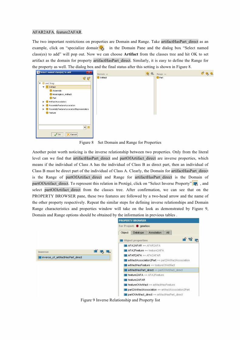
The two important restrictions on properties are Domain and Range. Take artifactHasPart_direct as an example, click on “specialize domain” in the Domain Pane and the dialog box “Select named class(es) to add” will pop out. Now we can choose Artifact from the classes tree and hit OK to set artifact as the domain for property artifactHasPart_direct. Similarly, it is easy to define the Range for the property as well. The dialog box and the final status after this setting is shown in Figure 8.
Figure 8 Set Domain and Range for Properties
Another point worth noticing is the inverse relationship between two properties. Only from the literal level can we find that artifactHasPart_direct and partOfArtifact_direct are inverse properties, which means if the individual of Class A has the individual of Class B as direct part, then an individual of Class B must be direct part of the individual of Class A. Clearly, the Domain for artifactHasPart_direct is the Range of partOfArtifact_direct and Range for artifactHasPart_direct is the Domain of partOfArtifact_direct. To represent this relation in Protégé, click on “Select Inverse Property” , and select partOfArtifact_direct from the classes tree. After confirmation, we can see that on the PROPERTY BROWSER pane, these two features are followed by a two-head arrow and the name of the other property respectively. Repeat the similar steps for defining inverse relationships and Domain Range characteristics and properties window will take on the look as demonstrated by Figure 9, Domain and Range options should be obtained by the information in previous tables .
Figure 9 Inverse Relationship and Property list

2.3.2.3 Create Individuals
Move on to the Individuals Tab and click on the “creat instance” icon under the INSTANCE BROWSER pane. For example, select the subclass Part, and create the 14 individuals prescribed in Table. After each individual of Part is created, we are able to see the property box that are attached to this class. For Part, the software system provides space for us to define the value of artifactHasFeature, part2ArtifactAssociation and partOfArtifact_direct. Based on Table 3, we can easily determine the property values for each inviduals of Part. Other individuals of all the classes in this ontology require the same work to determine the property values, which can be done based on corresponding tables offered earlier. Figure 10 gives the overall look of the individuals tab and the specific situation for the individual Lower_Housing.
Figure 10 Individuals of Reduction Gearbox ontology
2.3.2.4 Ontology Exploration
Choose Project>Configure and check “OWL Viz Tab” under Tab Widgets in the dialog box. OWL Viz Tab will show up. Use the show class hierarchy function to get the following clear structure of the gearbox ontology as shown in Figure 11.
Figure 11 OWL-Viz Plugin Function showing class hierarchy

2.3.3 Reasoning by Protégé and Racer
Racer is package that can help perform reasoning for an ontology in order to find any possible inconsistencies and fallacies within the system. This report use RacerPro 1.92 to conduct the analysis. Launch RacerPorter 1.92, if valid license file is placed correctly, Racer will be open and give the following prompt:
* ? Automatically connected to RacerPro 1.9.2 running on localhost:8088 (case: preserve)
* > (:OKAY "RacerPro 1.9.2 running on localhost:8088 (case: preserve)")
Now press “load” button under Profiles tab and choose the ReductionGearbox.owl ontology file to load the owl-ontology file successfully. This software gives a more detailed description of inner relations between the elements of the ontology. Figure 12 shows the Taxonomy plot.
Figure 12 RacerPro Interface
2.3.3.1 Inferred Individuals and Properties
After reasoning process, the output individuals of each class will be presented.
(1) Inferred Assembly Properties
Now the class Assembly is not empty anymore, see Table 8.

Table 8 Assembly inferred properties
(2) Inferred Meaningless_Artifact Individuals
Now after the reasoning, Meaningless_Artifact class is no longer empty. Two individuals of the class Artifact are reclassified as not well defined. There are Input_Axial_Assembly and Reduction_Gearbox_Assembly. As expected, the individual (Input_Axial_Assembly) with a self reference (inadmissible in assembly representation) is reclassified as element of this class. Also note the Reduction_Gearbox_Assembly is reclassified to this class since the inadmissible Input_Axial_Assembly is a sub-assembly of the Reduction_Gearbox_Assembly.
(3) Inferred ArtifactAssociation Properties
Inferred Properties ArtifactAssociation Individual artifactAssociation ArtifactAssociation2AFA
fc_1 Reduction_Gearbox_Assembly AFA_fc_1 fc_2 Reduction_Gearbox_Assembly AFA_fc_2 fc_3 Reduction_Gearbox_Assembly AFA_fc_3 fc_4 Reduction_Gearbox_Assembly AFA_fc_4 fc_5 Reduction_Gearbox_Assembly AFA_fc_5
Inferred Assembly Properties Assembly Individuals artifactHasPart assembly2ArtifactAssociation
Input_Axial_Assembly Input_Bearing_1 Input_Bearing_1
Input_Shaft
fc_2 fc_3 mc_1 mc_2
Input_Axial_Assembly
Output_Bearing-1 Output_Bearing-1
Output_Shaft Output_Gear Output_Key
fc_4 fc_5 fc_6 fc_7 mc_3
Reduction Gearbox Assembly
Input_Bearing_1 Input_Bearing_2
Input_Shaft Output_Bearing_1 Output_Bearing_2
Output_Shaft Output_Gear Output_Key
Lower_Housing Upper_Housing
Screw_1 Screw_2 Screw_3 Screw_4
fc_1 fc_2 fc_3 fc_4 fc_5 mc_1

fc_6 Output_Axial_Assembly AFA_fc_6 fc_7 Output_Axial_Assembly AFA_fc_7 mc_1 Reduction_Gearbox_Assembly AFA_mc_1 mc_2 Input_Axial_Assembly AFA_mc_2 mc_3 Output_Axial_Assembly AFA_mc_3
Table 9 ArtifactAssociation: inferred properties
(4) Inferred AssemblyFeatureAssociation Properties
Inferred Properties AFA Individuals AssemblyFeatureAssociation2ArtifactAssociation
AFA_fc_1 AFAR_fc_1 AFA_fc_2 AFAR_fc_2 AFA_fc_3 AFAR_fc_3 AFA_fc_4 AFAR_fc_4 AFA_fc_5 AFAR_fc_5 AFA_fc_6 AFAR_fc_6 AFA_fc_7 AFAR_fc_7 AFA_mc_1 AFAR_mc_1 AFA_mc_2 AFAR_mc_2 AFA_mc_3 AFAR_mc_3
Table 10 AssemblyFeatureAssociation: inferred properties
(5) Inferred AssemblyFeatureAssociationRepresentation Properties
Asserted Properties AFA2AFAR AFA2Feature
AFAR_fc_1
Threaded_Hole_1 Threaded_Hole_2 Threaded_Hole_3 Threaded_Hole_4
Thru_Hole_1 Thru_Hole_2 Thru_Hole_3 Thru_Hole_4
Thread_1 Thread_2 Thread_3 Thread_4
AFAR_fc_2 Input_Outer_Race_1
Input_Bearing_Seat_3
AFAR_fc_3 Input_Outer_Race-2
Input_Bearing_Seat_4
AFAR_fc_4 Output_Outer_Race_1
Output_Bearing_Seat_3

AFAR_fc_5 Output_Outer_Race_2
Output_Bearing_Seat_4
AFAR_fc_6 Output_Key_Side_1 Output_Shaft_Side
AFAR_fc_7 Output_Key_Side_2 Output_Gear_Side
AFAR_mc_1 Input_Gear-Teeth
Output_Gear-Teeth
AFAR_mc_2
Input_Inner_Race_1 Input_Inner_Race_2
Input_Bearing_Seat_1 Input_Bearing_Seat_2
AFAR_mc_3
Output_Inner_Race_1 Output_Inner_Race_2
Output_Bearing_Seat_1 Output_Bearing_Seat_2
Table 11 AssemblyFeatureAssociationRepresentation: inferred properties
3. Conclusion
In this project, we have successfully built an ontology to represent an assembly of a reduction gearbox by using Protégé-OWL. The inside structure of the part assembly relationships become extremely clear and can be drawn upon on for future study; this is exactly the most important advantage of ontology approach in manufacturing and product development field. Even if the interoperability between different systems is growing, the current PLM solutions are inefficient while screening data clustered in companies. This necessitates a need for a data analysis system. This scenario is due to the inherent drawback with the commonly used approaches, to give any sort of meaning to the stored data to help systems to understand/react immediately to the kind of information saved in a particular cluster. This problem is present in any entity that collects great quantity of data. Generally every entity has good knowledge of the kind of data in manages. However, this knowledge can be become complex if we refer to different subjects of a supply chain or to a set of divisions or facilities trying to share data in a PLM context. The aim of this work i.e., the development of OWL ontology for the assembly model fits the above mentioned scenario. The underlying reasons for the creation of the OWL of the assembly are: 1) A standard data structure developed directly in a Web-oriented language such as OWL: this assures the highest level of compatibility and diffusion; 2) New reasoning capabilities offered by the ontological approach: OWL is developed with the intent of supporting the growth of the Semantic Web and offers the possibility to give to the data structure not only a format but a meaning intelligible by a computer. This allows the machines to reason this ontology to deduct knowledge and more information from the stored data. The proposed OWL aims to address a data representation model for interoperability between software platforms with a capability of sharing meaningful stored data.