online monitoring and life extension of coke drums · vipul gupta manager-inspection, technical...
TRANSCRIPT

Vipul Gupta
Manager-Inspection,
Technical Services
Online Monitoring and Life Extension of
Coke Drums
Sohan S. Alva
GM-Inspection,
Technical Services
Vishal F. Yadav
Sr. Manager-Inspection,
Technical Services

▪ Introduction
▪ Details of Coke drums
▪ Coking/De-coking cycles
▪ Failure modes in coke drums & peripherals
▪ Inspection and monitoring used in MRPL
• Drum Laser data & severity categorisation
▪ Strain based engineering analysis observations
▪ Non-destructive testing (NDT) observations
▪ Repair methodology and job execution details
▪ Summary and Conclusion
Content

Introduction
Description Details
Commissioned in April 2014
Unit Licenser M/s Lummus Technology
Capacity 3.0 MMTPA
On-Stream Factor 8000 Hrs/yr (333.33 days)
Turn Down ratio 50%
Design feed TAN < 0.5
No. of Coke drums 4 nos.
No. of Heaters 2 nos.

Details of coke drums
Description Details
Manufacturer M/s ISGEC Yamunanagar
Total length 41457 mm
Internal Diameter 9144 mm / 180 inches
Design coke level 30774 mm
Metallurgy SA387 Gr 11 CL1 Base + SA240 410S Clad
Cylindrical Shell 10 nos. shell courses
Thickness of cylindrical shell
26 mm to 41 mm with min. 3 mm Clad
Feed entry nozzle Side feed

Coking and De-coking cycles

Failure modes in coke drums & peripherals
Location of failures
Morphology Causes
Shell & weld joints
• Bulging and cracking• Bowing/tilting (banana
effect)• Weld cracking at
tri-metal joints
• Cyclic thermo-mechanical loading• Uneven heating/cooling• Different thermal coefficient of
expansion.
Skirt and concrete foundation failures
• Key hole or weld joint Cracks
• Bulging / Buckling• Damage to bolts /
structural concrete
• Cyclic thermo-mechanical fatigue• Uneven load distribution• Drum movement
/Corrosion/Vibration
Piping failures • Cracking • Vibration induced mechanical fatigue

Inspection and monitoring used in MRPL
Techniques Occasions/Purpose Results
Laser Mapping and Remote Visual inspection
• Initial inspection• August 2017• August 2018
• No fabrication damage• Localized bulging-2017• Band bulging-2018
Strain based Engineering analysis
• Strain analysis with August 2017 & 2018 Laser data
• Identified areas with high propensity of cracking
PAUT/TOFD • For identifying bulge induced and weld cracking at higher PSI locations.
• Confirmed bulge induced and weld cracking
Internal inspection & DPT/MPT
• April-May 2019 • Data matched with PAUT/TOFD findings

Drum Laser data & severity categorisation
Drum C Drum D
Laser data Radial growth in mm Radial growth in mm
2017/2018 33 to 60 mm 24 to 78 mm
Range for ratio of [(R-Rn)/Rn]x 100
Categorization of severity
MRPL drum severity categorisation
0%-1% Slight 0-45 mm
1%-1.5% Moderate 45-68 mm
1.5% >= Severe 69 and above
R- Actual radius measured by Laser mappingRn- Nominal radius of drum

Laser Mapping data of Drum C

Laser Mapping data of Drum D

PSI data nomenclature & Drum C, D data
Drum C Drum D
PSI data (%) Max (+)ve Max (-)ve Max (+)ve Max (-)ve
2017 data (+)45.9 (-)22.2 (+)47.8 (-)29.7
2018 data (+)51.7 (-)21.3 (+)47.1 (-)25.9
Plastic Strain Index (PSI) values Failure initiation location
Positive (+ve) Inner surface of drums
Negative (-ve) Outer surface of drums

PSI plots of Drum C & D

PSI analysis: Conclusion & Recommendation
▪ Faster deterioration in SA-387 Gr 11 Class 1 drums is attributed to
lower strength than Class 2 material typically used in industry.
▪ Inspection of identified bulging zones from inside and outside
surface using Visual, DPT, UT.
▪ If cracks observed, design and implement high-quality weld overlay
repairs at first shutdown.
▪ Annual laser scanning and strain analysis for bulge assessment

NDT observations
▪ Inspection performed during de-coking cycles from outside surface
▪ PAUT using angle shear beam (for locating ID cracks) and zero deg longitudinal beam (for locating clad disbonding) performed.
▪ PAUT and TOFD performed for circumferential weld seam examination.
▪ Weld cracking observed at the interface of tri-metal joint.
▪ Multiple crack like indications observed in shell plate bulge area scanning, in line with PSI analysis data.
▪ Circ. length of defect 6-760 mm & depth 1.3-8 mm (from drum ID).
▪ Three category of defects: 1) up to 50% of clad 2) > 50% and within clad 3) Depth more than clad thickness and penetrating into base metal

Methodology for AWO repair
▪ Initial inspection, repair area defect confirmation and marking
▪ Recording of initial data
1) Grid thickness-for overlay thickness check
2) Dimensional check-for distortion check
3) Hardness check
4) MPI of outside surface for ruling out OD defects.
▪ Clad removal by arc gouging without pre-heating & finish grinding
▪ CuSO4 check, PMI and DPT of the finished surface.
▪ Grit blasting prior to welding to meet SA-3 & primer application
▪ Fixing of Pre-heating/Post heating pads on drum outer surface,
AWO track fixing and machine sequencing.
▪ Preheating, sealing of clad interface and 1st layer AWO welding

Methodology for AWO repair
▪ Visual inspection of finished 1st layer, switching off preheating and
data collection
▪ Visual inspection of finished 2nd layer (final layer), including taper at
the interface.
▪ DPT of the interface and post heating.
▪ Visual inspection and DPT after post heating.
▪ Removal of AWO tracks and DPT of tack welds after grinding on
inner and outer surface (for thermocouple locations)
▪ PAUT from outer surface of bulge area and PAUT and TOFD for
weld seam area.
▪ Visual inspection and DPT of the insulation support cleats and outer
surface of the drums.

Details of job execution
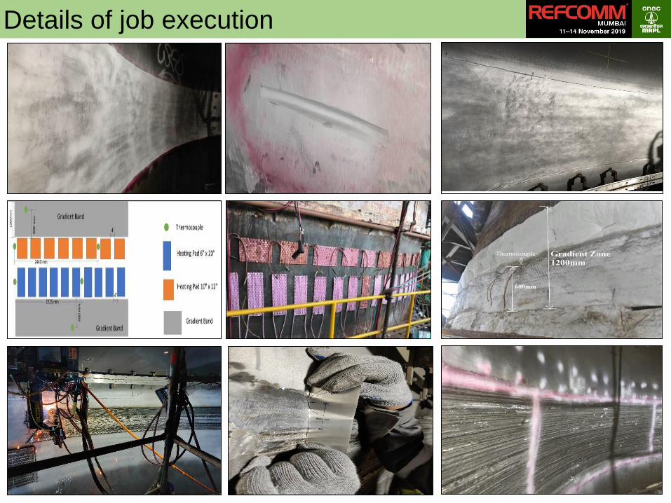
Details of job execution

Drum C overlay extent
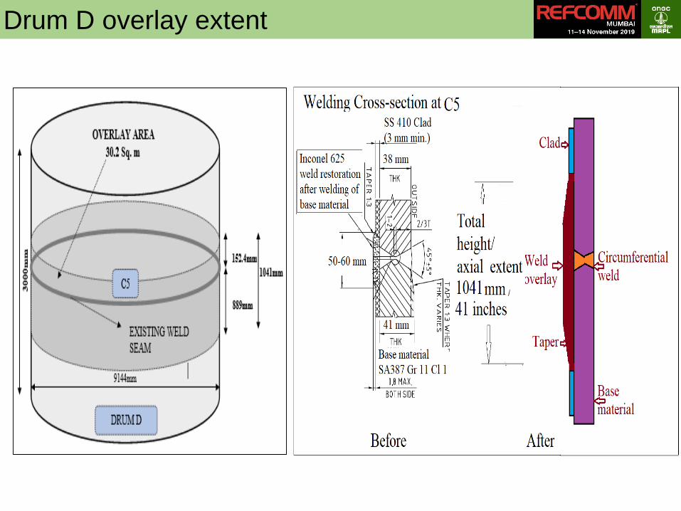
Drum D overlay extent

Summary and Conclusion
▪ Due to cyclic service of the drums, regular monitoring is essential
▪ Laser mapping is the starting point, followed by engineering analysis
based on bulge severity
▪ Results of engineering analysis to be confirmed by further NDT to
decide on need for repair action
▪ Full circumferential band repair using AWO is recommended over
patch repair of bulges
▪ Multiple elevation repairs requires planned sequencing of jobs
▪ Inspection of outer surface of drums is highly recommended post
AWO
