onl 074 097 iq-sensor-net 3-mb us-pdf
TRANSCRIPT

> 1000 systems sold
> 10
years of experience
IQ Sensor Net
For information visit www.WTW.com for a customer care center near you74
I Q S e n S o r n e t
F l e x i b i l i t y t h r o u g h d i g i t a l t e c h n o l o g y – T h e I Q S e n S o r n e t f r o m W T W
With the modular IQ SenSor net, WTW has set standards in the field of continuous on-line measure - ment. Meanwhile, WTW can look back on a more than 10-year success history with thousands of systems and sensors sold. The development of the system has progressed steadily. The list of available parameter measured and the technologies for communica-tion continue to grow. Based on instrument and sensor technology that has been field-proven many times over, IQ SenSor net offers an impressive level of performance and flexibility that is unique in this form.
The system can be optimally adapted to any conceivable measurement task, even under special on-site conditions. The IQ SenSor net communication system allows the easy integration of multiple measurement locations. This results in a significant reduction in costs while maintaining full functionality.
I Q S e n S o r n e t
• One system for all parameters
• Any sensor combination possible
• Up to 20 sensors may be connected
• Simple extension of system at any time
• Simple installation using two-wire technology
• Digital signal transmission
• Integrated lightning protection

For information visit www.WTW.com for a customer care center near you
Acc
esso
ries
Sam
ple
rsSa
mp
le
Prep
arat
ion
An
alyz
erM
onit
ors
IQ S
enSo
r n
etG
ener
al D
escr
ipti
on
of M
eter
s
75
I Q S e n S o r n e t – P h i l o s o p h y
I Q S e n S o r n e t – t h e m u l t i - p a r a m e t e r m e a s u r i n g s y s t e mThe System 2020 XT is the flexible solution for today and for the future. It’s fully modular design “keeps on growing” to keep pace with your growing demand. This flexibility makes the system very appealing also for small, medium, and larger sewage plants. Any conseivable application can be managed including discharge measuring with the parameters turbidity, pH, conductivity and temperature, furthermore the control of nitrification/denitrification and complete sewage plant ana-lytics can be supported by one single system. All this at a low investment cost and highly economical operation – with an easy to handle system.
Any sensor combination possible
The parameter-specific sensors are equipped with a standard interface for communication with central components. Thus, different types of sensors or parameters can easily be connec-ted to the system. The user can freely select parameters and is only restricted by the maximum number of sensors. Thus, application-specific tasks such as inlet or outlet measurement in wastewater treatment plants or simultaneous measure-ment in several aeration basins can be easily and economic-ally accomplished using a single system.
Up to 20 sensors may be connected
WTW offers IQ sensors for more than 15 different parame-ters, including new sensors for carbon parameters, nitrate, nitrite that feature a unique cleaning system, and for sludge level measurement. Numerous special sensors desi-gned for specific applications are available for each type of parameter. WTW has available a total of 31 different IQ sensors that can be combined as required. When a sensor is connected to the IQ SenSor net, it is recognized auto-matically and the measured value is displayed immedia-tely. The software is designed in such a way that future parameters can readily be integrated into the existing sys-tem. With this intelligent structure, the system can easily be extended or modified to incorporate up to 20 sensors.
Because the calibration data are stored in the sensor, the calibration of IQ sensors can be processed in the laboratory.
I Q S e n S o r n e t S y s t e m P h i l o s o p h y

For information visit www.WTW.com for a customer care center near you76
C o n s i s t e n t l y d i g i t a l a n d m o d u l a rFunctional units, such as power supply units, outputs, relays, etc., that were ori-ginally incorporated in a conventional monitor, have now been modularized – at both the functional and mechanical levels. Communication between indivi-dual components and between sensors is digital.
Digital transmission technology now allows transmission over large distances between the separate system components. Consequently, these components can be placed at almost any location within the system.
The connection is a shielded 2-wire cable that not only transports digital infor-mation but also provides the low-voltage power supply to the individual com-ponents. With these features the system is able to meet such requirements as
• a high degree of flexibility in positioning equipment (measurement locations can be installed at great distances)
• local orientation of functionality (modules are installed where the functionality is required) and
• simple installation and system extension
E x t r e m e l y f l e x i b l e a n d e c o n o m i c a lThe fact that sensors and system units can be placed at almost any desired location in the wastewater treatment plant, coupled with a simple and secure connection technique, result in the remarkable flexibility of the IQ SenSor net. Moreover, the IQ SenSor net is highly cost efficient, a direct consequence of the intelligent technology it incorporates:
• A decrease in costs as the number of measurement locations rises, since each additional parameter requires only one additional sensor
• Point-to-point cable connections between individual measurement locations is not required – resulting in considerable savings in cable and installation costs
• The system can be simply and economically extended at any time

For information visit www.WTW.com for a customer care center near you
Acc
esso
ries
Sam
ple
rsSa
mp
le
Prep
arat
ion
An
alyz
erM
onit
ors
IQ S
enSo
r n
etG
ener
al D
escr
ipti
on
of M
eter
s
77
F e a t u r e s a n d f u n c t i o n s
o f t h e I Q S e n S o r n e t s y s t e m
Power supply and communication in the IQ SenSor net
Both power and communications within the system are transmitted via a special shielded two-wire cable referred to as the SNCIQ SenSor net cable. The conductors are color-coded to assist in correct connection. Should polarity be reversed accidentally, correct function of the system is fully guaranteed. Because the supply voltage within the system is approx. 24 VDC, there is no risk of coming into contact with dangerously high voltages.
Digital signal transmission
The complete system communication is digital. This ensures high measu-rement accuracy even with large distances between system components. Digital signal transmission is immune to external EMC interferences.
Integrated lightning protection / high EMC immunity
All IQ SenSor net components offer integrated lightning protection in proven WTW quality as a standard feature. This eliminates the need for additional external protective systems. The high EMC immunity of each of the individual components contributes to the maximum operating safety and high availability of the system.
Extension of system components
When the IQ SenSor net is extended, the new components are automati-cally recognized and integrated immediately.
S y s t e m 2 0 2 0 X T – F e a t u r e s
Exchanging sensors
Sensors can be exchanged during operation without having to shut down the system. All settings from the old sensor can easily be taken over into the new sensor.
Allocation of inputs and outputs as required
Each input component of the system (sensor) can be allocated to any out-put (mA/relay). Multiple allocations are possible.
Error diagnosis
The system status and all events that occur are recorded in an internal LogBook. The display provides the user with detailed information regarding error diagnosis and troubleshooting.
Mounting
IQ sensors can be installed directly in open channels or basins using field-proven accessories. Various flow-thru vessels are available. Special moun-ting kits are provided for mounting modules in panels and on top hat rails, walls and handrails. The new SSH/IQ sun shield can be used in combina-tion with all current WTW mounting stands for installation in field.

For information visit www.WTW.com for a customer care center near you78
F e a t u r e s a n d f u n c t i o n s
Mechanical docking of a terminal
A Terminal TC 2020 XT can be easily connected to each module. The electrical contact for the power supply and data communication is made simul taneously with the mechanical connection.
Stack mounting of modules
Up to three modules can be mechanically connected to form a stack. Simultaneous mechanical and electrical connection to data and power trans-mission. The individual modules of the stack can be accessed at any time with-out dismantling the stack by simply undoing two lateral screws.
Distributed mounting of modules
All modules can be installed anywhere in the system, both in dividually and in stacks. When not stacked, system com ponents are connected via the 2-wire shielded SNCIQ SenSor net cable. Each Sensor Net connection of a system component can be used to extend the IQ SenSor net cable. Furthermore, IQ sensors can also be connected directly to the Sensor Net terminals.
Terminator function of the modules
Each module is equipped with a terminator function. This function is a termina-ting resistor that can be switched on and off as required. This is important whe-never a module is located at the end position in the Sensor Net.
Local identity function
The local ID function is integrated in each module in the form of a memory component. The memory can be used to store relevant information when con-figuring the system such as location and designation of the measurement loca-tion and the sensors connected there. When connecting a terminal, this infor-mation is output and facilitates rapid localization of sensors for calibration pur-poses.
Diagnosis via LEDs
Each module is provided with two LEDs (yellow/red) for diagnostic purposes. They are located on the side of the module and are clearly visible at all times. They indicate whether the respective module is operational (power supply/ data communication).
o f t h e m o d u l e s

For information visit www.WTW.com for a customer care center near you
Acc
esso
ries
Sam
ple
rsSa
mp
le
Prep
arat
ion
An
alyz
erM
onit
ors
IQ S
enSo
r n
etG
ener
al D
escr
ipti
on
of M
eter
s
79
S y s t e m 2 0 2 0 X T – Te c h n o l o g y
I Q S e n S o r n e t s y s t e m t e c h n o l o g y
T h e I Q S e n S o r n e t c o n s t r u c t i o n k i t
The IQ SenSor net system consists of a variable number of system components with different functions.
T h e i n d i v i d u a l c o m p o n e n t s a n d t h e i r p r i m a r y f u n c t i o n s a r eController and terminal Controller Controls all communication within the system
Terminal Display of measurements, operation and system configu-ration (“Human Machine Interface”)
Modules Power supply modules Power supply for system components
Combined output module Transmission of measured data or message/alarm func-tions (mA/relays)
Branching modules System branching and sensor connection
Sensors IQ sensors and connection modules for passive sensors
Measurement of parameters
Cables Sensor connection cable Cables for connecting sensors to modules
Module connection cable Cables for connecting modules to remote measuring points
Module connection cable, ground installation
Cables for connecting modules to remote measuring points, specifically for the ground installation.
Simple installation at the process tank (on-site)

For information visit www.WTW.com for a customer care center near you80
I Q S y s t e m sSensor network or single measuring stations – an easy choice …
The planning begins with a basic decision between 2 systems
Single point measuring system
System 182 (1 to 4 sensors)
• Decentralized system for 1 to 4 sensors with inte-grated terminal.
• Models with integrated analog or digital outputs (i.e. RS-485/ field bus connections PROFIBUS or MODBUS) available
Example for a single point measuring system using 4 sensors
see page 94
SPS
Schaltwarte
Portable display TC 2020 XT
Sensor network System 2020 XT
(up to 20 sensors)
• Central (network) and decentralized system for up to 20 sensors possible – extendable by up to 3 terminal / controller units for flexible installation within the network.
• Digital and / or analog outputs, can be combinated and extended by modules and inte-grated within the network.
Example for a central network with system 2020 XT using 14 sensors see page 82
Control room

TSS
O2 CondpH
Turb IFLNH4NO3 NO3
NO2 CSBSAC
TSS
TOC
For information visit www.WTW.com for a customer care center near you
Acc
esso
ries
Sam
ple
rsSa
mp
le
Prep
arat
ion
An
alyz
erM
onit
ors
IQ S
enSo
r n
etG
ener
al D
escr
ipti
on
of M
eter
s
81
S y s t e m s & S e n s o r s
pH / ORP
page 19 – 22
Turbidity and suspended solids
page 34 – 37
SW
SWSW SW SW
Sludge level
page 70
Ammonium and nitrate
page 44 – 50
Nitrite, Nitrate, COD / TOC / DOC / BSB / SAC
page 51 & 60/61
Dissolved Oxygen
page 8 – 16
Conductivity
page 28 – 31
I Q S e n s o r sOne connection for all IQ sensors – via the universal SACIQ sensor cable
The standard version of high grade stainless steel is suitable for process and indus-try. All media contacting components of the seawater versions are made of tita-nium and plastic and are therefore extremely resistant to corrosion.
SPS
Schaltwarte
IQ SENSOR NET
island 2
wireless connection within IQ SENSOR NET
data readout
Communications with PLC
field bus- PROFIBUS- MODBUS
Ethernet- Ethernet IP- MODBUS TCP/IP- Profinet
IQ SENSOR NET
island 1
integration in networks and access to IQ SENSOR NET
Access to IQ SENSOR NET
Internet
using tablet, PC, mobile, ...
IP addressIQ SENSOR NET
For information visit www.WTW.com for a customer care center near you82
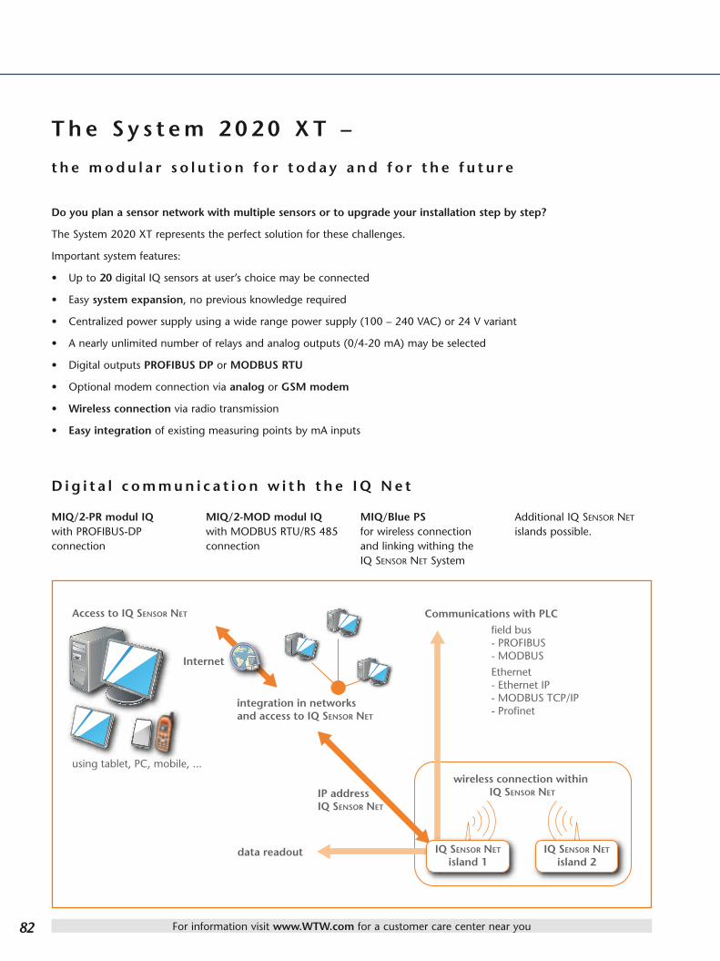
T h e S y s t e m 2 0 2 0 X T –
t h e m o d u l a r s o l u t i o n f o r t o d a y a n d f o r t h e f u t u r e
Do you plan a sensor network with multiple sensors or to upgrade your installation step by step?
The System 2020 XT represents the perfect solution for these challenges.
Important system features:
• Up to 20 digital IQ sensors at user’s choice may be connected
• Easy system expansion, no previous knowledge required
• Centralized power supply using a wide range power supply (100 – 240 VAC) or 24 V variant
• A nearly unlimited number of relays and analog outputs (0/4-20 mA) may be selected
• Digital outputs PROFIBUS DP or MODBUS RTU
• Optional modem connection via analog or GSM modem
• Wireless connection via radio transmission
• Easy integration of existing measuring points by mA inputs
D i g i t a l c o m m u n i c a t i o n w i t h t h e I Q N e t
MIQ/2-PR modul IQ with PROFIBUS-DP connection
MIQ/2-MOD modul IQ with MODBUS RTU/RS 485 connection
MIQ/Blue PS for wireless connection and linking withing the IQ SenSor net System
Additional IQ SenSor net islands possible.

SPS
Schaltwarte
For information visit www.WTW.com for a customer care center near you
Acc
esso
ries
Sam
ple
rsSa
mp
le
Prep
arat
ion
An
alyz
erM
onit
ors
IQ S
enSo
r n
etG
ener
al D
escr
ipti
on
of M
eter
s
83
S y s t e m 2 0 2 0 X T
S y s t e m a r c h i t e c t u r e M I Q / T C 2 0 2 0 X TThe terminal/controller MIQ/TC 2020 XT can be operated as either controller (permanently installed with the system) as also as mobile terminal. This function can easily be configured with the software by each user. The status LED indicates the selected function and informs about any possible incidents.
Inlet:pH, Cond, Ammonium, Nitrate, Nitrite, COD/TOC/DOC/BOD/SAC
Aeration:D.O., Ammonium, Nitrate, Nitrite, TSS, pH, Phosphate
Post-Sedimentation:Turbidity, TSS, Sludge level
Effluent:Ammonium, Nitrate, Nitrite, pH, Conductivity, D.O., Turbidity, COD/TOC/DOC/BOD/SAC
Portable display TC 2020 XT
control room

For information visit www.WTW.com for a customer care center near you84
S y s t e m 2 0 2 0 X T ( U S B ) S y s t e m 2 0 2 0 X T ( C o n n e c t )
• USB interface
• Electronic-Key function
• IQ-LabLink function
• LAN & USB interface
• Integrated Web server
• Various TCP/IP Communication protocols
• Profibus and Modbus versions
Page 88/89starting on page 85

For information visit www.WTW.com for a customer care center near you
Acc
esso
ries
Sam
ple
rsSa
mp
le
Prep
arat
ion
An
alyz
erM
onit
ors
IQ S
enSo
r n
etG
ener
al D
escr
ipti
on
of M
eter
s
85
S y s t e m 2 0 2 0 X T ( U S B )
Te r m i n a l / C o n t r o l l e r M I Q / T C 2 0 2 0 X T
The terminal / controller MIQ/TC 2020 XT presents the core of each IQ SenSor net System 2020. Its high-performance processor coordinates all tasks within the network. Via the USB interface an extremely fast data exchange via USB memory stick to any external sys-tem directly is possible. The system-status LED gives reliable and fast information regarding function and status of system.
When integrating two MIQ/TC 2020 XT in the system, the dual-processor function increases the system stability and therefore also availability of the entire system.
Can be operated as terminal and controller all-purpose solution (constantly installed) or as mobile terminal solution.
• Multi-functional USB interface• Increased system stability through dual-processor function
Network integration • Remote communication • Remote maintenance
Status LED displayEach MIQ/TC 2020 XT terminal/controller shows a LED for diagnostic purposes on the front. This LED shows normal and malfunctions of the system at a glance.
Multi-functional USB interface• IQ-LabLink function• Electronic-Key function• Storage of configuration• Storage of calibration• Logbook recording• Storage of recorded data (data logging function)• Software upload
• In case of any failure regarding the central unit (terminal/controller function) the second unit fully automatically takes over both functions (goes fully automatically from the plain terminal operation to the terminal /controller operation).
• Status LED indicates any failures

For information visit www.WTW.com for a customer care center near you86
I Q - L a b L i n k – t h e l i n k t o t h e w o r l d o f l a b o r a t o r y
IQ-LabLink enables a safe data exchange between the IQ SenSor net and the laboratory instrument. The exchange is processed via a common USB memory stick, serving as data medium between the online system and the laboratory instrument. The condition is that both instruments feature this function and are equipped with a USB interface. The first WTW instruments to include this function are the two new spectrophotometers photoLab® 6100 VIS and photoLab® 6600 UV-VIS ( laboratory instruments) and the terminal/controller MIQ/TC 2020 XT with access to the IQ SenSor net.
Application example: Matrix adaption with VARiON®Plus
The multi-parameter sensor measures ammonium and nitrate at the same time. The ammonium measure-ment is dynamically com-pensated by the separate measurement of potassium. As every waste water has its individual matrix, a preci-sion-adaption is processed occasionally. The values for the matrix adaption are determined using a pho-tometer and provided to the sensor. The value entry was processed manually up to now.
Matrix adaption via IQ-LabLink
Step 1, IQ terminal:
Automatic generation of job files on a USB memory stick with actual sensor values, parameters, description of mea-suring site and the automatic allocation of job reference number for a unique identification.
Step 2, photometer:
After inserting the USB memory stick, the instrument identifies the job file, asks for the measurement with the according parameters, gives advice for supporting the correct operation, stores all determined data back on the job file and verifies the completeness.
Step 3, IQ terminal:
Complete reading of data related to the matrix adaption by pressing one button, without any interruption of the online measurement.
I Q - L a b L i n kAdvantages at a glance:
• Software supported routines for the safe data transfer from laboratory to online systems.
• Safe and easy allocation of online and laboratory measurement via job files and functions.
• Integrated help functions for correct processing.
• Check for completeness and verification.
• Complete reading of all data using one button without any interruption of the online measure-ment.

For information visit www.WTW.com for a customer care center near you
Acc
esso
ries
Sam
ple
rsSa
mp
le
Prep
arat
ion
An
alyz
erM
onit
ors
IQ S
enSo
r n
etG
ener
al D
escr
ipti
on
of M
eter
s
87
E l e c t r o n i c - K e y f u n c t i o n
S y s t e m 2 0 2 0 X T ( U S B )
E l e c t r o n i c - K e y f u n c t i o n w i t h p r o g r a m m a b l e a c c e s s p e r m i s s i o n
Function:
When the Electronic-Key function in the IQ SenSor net system is activated, the USB memory stick works like an electronic key giving access to the system.
A coded file is therefore stored on the USB memory stick. After reading the file access is activated to the system.
It is also possible, to release only certain functions in order to personalize access.
• Protection against non-authorized access
• Individual access permission

For information visit www.WTW.com for a customer care center near you88
N E W
S y s t e m 2 0 2 0 X T ( C o n n e c t )
T h e n e w c o n t r o l l e r f a m i l y M I Q /M C 2 b y W T W
Ethernet connection - web server and much more
Easiest network connections - local and via internet
Measured values are available worldwide at any time
The availability and retrieval of online measurement values - at any time and from anywhere in the world - with the assis-tance of network connected computers and smart phones, becomes increasingly more important for users in industry and wastewater treatment plants. Modern online measure-ment technology must therefore provide a simple and cost-effective integration into local networks, and also into the Internet.
IQ SenSor net measured values displayed via web browser/internet

For information visit www.WTW.com for a customer care center near you
Acc
esso
ries
Sam
ple
rsSa
mp
le
Prep
arat
ion
An
alyz
erM
onit
ors
IQ S
enSo
r n
etG
ener
al D
escr
ipti
on
of M
eter
s
89
S y s t e m 2 0 2 0 X T ( C o n n e c t )
Ethernet/LAN interface and Web server included – ready to use
WTW continued to raise the bar with the new controller family MIQ/MC2 that has integrated an Ethernet / LAN interface as standard. The integration through existing rou-ters in system networks and the Internet must be implemen-ted easily and inexpensively without additional accessories. Thanks to the integrated Web server, data can be viewed at anytime with Internet-enabled devices such as PCs, tablet PCs or smartphones via web browsers.
Housings of the new MIQ/MC2 family with integrated Ethernet/LAN and USB interface.
Integration of the IQ SenSor net system via Ethernet/LAN and routers into a local network or via the Internet into a second local network.

For information visit www.WTW.com for a customer care center near you90
G e n e r a l Te c h n i c a l D a t a S y s t e m 2 0 2 0 X TS y s t e mCertifications ETL, cETL (conforms with relevant UL and Canadian standards), CEElectromagnetic Compatibility EN 61326, Class B; FCC Class A, EMC for indispensable operationIntegrated Lightning Protection According to EN 61326 enhanced overvoltage protection for the entire system, implemented in each componentConnection Medium Cable IQ SenSor net cable SNCIQ or SNCIQ/UG (underground cable with additional PVC coating):
2-wire with shield; 2 x 0.75 mm2; Filler cord for easy connection of shield: 0.75 mm2; pressure resistant to 10 barConnection Characteristics Power supply and data transmission on these wires; resistant to polarity reversal with respect to switched shield and
inner conductor (no damage); comprehensive EMC shield control; cable topology within IQ Sensor Net system as required, e.g. in the form of a line, tree, star, multiple star Total cable length: max. 1.000 m/1094 yds (without signal amplifying), with signal amplifying module MIQ/JBR additional 1.000 m/1094 yds
Connection Medium Radio Radio transmission Class 1 with a range of 100 m/109 yds (max. 300 m/328 yds)Connection Characteristics Data transmission, separate power supply necessary for each island
Controller Terminal-/Controller MIQ/TC 2020 XT Controller MIQ/MC2MIQ Module Coupling at Rear Combined mechanical and electrical connection, for rapid coupling to MIQ modulesUSB interface USB-A (host) USB-AEthernet port – RJ45 socket or LSA terminal strip can be usedDisplay Graphic display; resolution: 320 x 240 pixel; visible area:
4.49 x 3.39 in. (114 x 86 mm), black/white, backlit–
Control Functions/Function Keys
5 operating keys: 3 master keys for functions: Measurement (M), calibration (C), set/system settings (S), 2 keys for: confirmation/switching menu O.K. (OK), Escape (ESC)
4-directional button for rapid selection of software functions and input of alphanumeric values
–
Datalogger Data memory for up to 525,600 data setsElectric Supply Directly via the IQ SenSor net when coupled to MIQ moduleAmbient Conditions Operating temperature: – 4 °F … 131 °F (– 20 °C … + 55 °C)
Storage temperature: – 13 °F … 149 °F (– 25 °C … + 65 °C)Housing Material ASA (Acrylonitrile-Styrene-Acryloesterpolymer)Protection Rating IP 66 / equivalent to NEMA 4X (not suitable for conduit connection)Dimensions (W x H x D) 8.27 x 6.69 x 1.57 in. (210 x 170 x 40 mm) 5.67 x 6.81 x 2.05 in. (144 x 173 x 52 mm)Weight Approx. 1.54 pounds (0.7 kg)Guaranty 3 years for defects of qualityModulesMIQ Module Coupling at Front Combined mechanical and electrical connection for rapid docking and removal of the MIQ/T2020 (PLUS) terminal and
the MIQ/TC 2020 XT controller, and for docking additional modulesMIQ Module Coupling at Rear Combined mechanical and electrical connection for docking additional modules,
a total of 3 modules as a stack mounted unit Cable Feeds 4 screw cable glands M 16 x 1.5Terminal Connections Screw terminal strips
Terminal area for solid conductors: 0.2 … 4.0 mm2 Terminal area for flexible conductors: 0.2 … 2.5 mm2 accessible by opening cover
IQ SenSor net Terminal Connections
Terminal connections for the IQ SenSor net are available on each module and can be used as required: - for connecting sensors - as an input/output or for looping through/branching of the IQ SenSor net cable
Other Functions Two LEDs, yellow and red, for monitoring the operating voltage of the IQ SenSor net; IQ SenSor net connection, resi-stant to reversed polarity; Integrated local identity function; Integrated switchable terminal resistor (SN terminator)
Electric Supply Directly via the IQ SenSor net
Ambient Conditions Operating temperature: –4 … 131 °F (– 20 … + 55 °C); Storage temperature: –13 … 149 °F (– 25 … + 65 °C)
Housing Material PC – 20 % GF (polycarbonate with 20 % fiberglass)Protection Rating IP 66 / equivalent to NEMA 4X (not suitable for conduit connection)Dimensions (W x H x D) 5.67 x 5.67 x 2.05 in. (144 x 144 x 52 mm)Weight Approx. 1.1 pounds (0.5 kg)Guaranty 3 years for defects of qualitySensorsMechanical Connections for Accessories
Connection slot; Connection screw thread G 1”
IQ Sensor Connection Cable Combined mechanical and electrical connection for rapid attachment and exchange of sensors. Consists of jack plug and pressure-resistant screw connection. Cable lengths: 1.64 – 7.66 – 16.40 yds (1.5 – 7.0 – 15.0 m)/ 21.87 – 54.68 – 109.36 yds (20 – 50 – 100 m) in sea water design available. Storage temperature: – 13 °F … 149 °F (– 25 °C … + 65 °C) Operating temperature: – 4 °F … +131 °F (– 20 °C … + 55 °C)

For information visit www.WTW.com for a customer care center near you
Acc
esso
ries
Sam
ple
rsSa
mp
le
Prep
arat
ion
An
alyz
erM
onit
ors
IQ S
enSo
r n
etG
ener
al D
escr
ipti
on
of M
eter
s
91
All IQ sensors are connectable; for ordering information see each parameter chapter. An overview of all connectable sensors can be found in our brochure
“Product Details”.
*Via the software adjustable by user.
IP 66 3 Year Guaranty
cETLus
S y s t e m c o m p o n e n t s a n d f u n c t i o n sTerminal/Controller
Model Function Order No.
Central Control Unit TC 2020 XT(Operation in MODBUS: terminal/controller)*
Central terminal/controller unit: is required to be installed once at any point, remains in the system, cannot be removed. Operation mode is shown through LED.
470 000
MIQ/TC 2020 XT-H3 Multi-parameter measuring converter, consisting of the components MIQ/TC 2020 XT + MIQ/CR3 + MIQ/PS, 100 – 240 VAC main voltage, 3 analog outputs (0/4-20 mA) and 3 relay outputs, up to 20 free selectable IQ sensors can be connected
470 016
MIQ/TC 2020 XT-H3 C6 Multi-parameter measuring converter, consisting of the components MIQ/TC 2020 XT + MIQ/C6 + MIQ/PS, 100 – 240 VAC main voltage, 6 analog outputs (0/4-20 mA) up to 20 free selectable IQ sensors can be connected
470 017
Controller
MIQ/MC2 Module IQ/Micro Controller; is required to be installed once at any point; with fully automatic air-pressure compensation and USB + LAN interface
471 015
MIQ/MC2-MOD Module IQ/Micro Controller with fully automatic air-pressure compensation and MODBUS RTU / RS 485 connection and USB + LAN interface
471 016
MIQ/MC2-PR Module IQ/Micro Controller with fully automatic air-pressure compensation and PROFIBUS-DP connection and USB + LAN interface
471 017
M I Q M o d u l e s
Model Function Order No.
Power Supply MIQ/PS for 100 – 240 VAC Depending on the power consumption up to 6 modules can be installed in the system. 480 004
MIQ/24V for 24 VAC/24 VDC 480 006
Output Modules(analog)
MIQ/CR3 with 3 analog (0/4-20 mA) and 3 relay outputs
With any combination 480 014
MIQ/C6 with 6 analog outputs (0/4-20 mA)
480 015
MIQ/R6 with 6 relay outputs 480 013
Output Modules(Digital)
MIQ/2-MOD Module IQ with fully automatic air-pressure compensation and MODBUS RTU / RS 485 connection
471 018
MIQ/2-PR Module IQ with fully automatic air-pressure compensation and PROFIBUS-DP connection
471 019
Magnetic valve module MIQ/CHV PLUS Magnetic valve module for automatic controlled cleaning via compressed air 480 018
Linking modules MIQ/JB MIQ/JB with 4 connections (for IQ Net or IQ sensors) 480 008
MIQ/JBR MIQ/JBR, same as MIQ/JB additionally with amplifier signal for long cable distances (> 1 km total length)
480 010
Connecting modulePower input
MIQ/IC2 MIQ/IC2 with 2 inputs for 0/4-20 mA signalsEnables the connection of separate measuring transmitters and analyzers to the IQ Net
480 016
Radio communication module
MIQ/Blue PS For wireless connection and linking within the IQ SenSor net system 480 021
S y s t e m 2 0 2 0 X T

For information visit www.WTW.com for a customer care center near you92
I Q S e n S o r n e t p e r f o r m a n c e d a t a
All components within the system require a specific electric power supply. Due to the enormous flexibility of the system, an infinite number of variations are possible. Therefore, a balance sheet must be drawn up after selecting the components. This is easily done by totaling the power consumption of the individual components and checking whether the sum exceeds the power provided by a particular power supply unit. If so, the available power can be increased by installing additional or more powerful power supply units.
Power consumption in Watts
Number of power supply units
MIQ/PS≤ 18 Watts 1 power supply unit18 - 36 Watts 2 power supply units36 - 54 Watts 3 power supply units55 - 72 Watts 4 power supply units73 - 90 Watts 5 power supply units91 - 108 Watts 6 power supply units
Additional cable losses generally do not need to be taken into account for installations where the main consumers are near (< 164 yds/150 m) the next power supply and the overall cable length does not exceed 437 yds (400 m). In systems with greater cable lengths, approx. 1 watt of power loss per additional 109 yds (100 m) of cable have to be considered. These standard values apply when using specified IQ SenSor net cable SNCIQ.
Multi-parameter monitor for any 4 parameters, with 6 analog outputs
MIQ/TC2020 XT + MIQ/PS + MIQ/C6 (6 x mA) + 4 IQ sensors
E x a m p l eOutlet measure ment with the following parameters: turbidity, pH, dissolved oxygen, conductivity and temperature
Components: Power consumption or power supply
One power supply unit MIQ/PS is sufficient for the complete system consisting of four connected sensors.
The system comprises a buffer/reserve of approx. 9 watts. The system can be accordingly extended sensors and components.
MIQ/PS + 18.0 Watts
MIQ/TC 2020 XT – 3.0 Watts
MIQ/C6 – 3.0 Watts
VisoTurb® 700 IQ – 1.5 Watts
SensoLyt® 700 IQ – 0.2 Watts
TriOxmatic® 700 IQ – 0.2 Watts
TetraCon® 700 IQ – 0.2 Watts
Total Σ: + 9.4 Watts

For information visit www.WTW.com for a customer care center near you
Acc
esso
ries
Sam
ple
rsSa
mp
le
Prep
arat
ion
An
alyz
erM
onit
ors
IQ S
enSo
r n
etG
ener
al D
escr
ipti
on
of M
eter
s
93
S y s t e m 2 0 2 0 X T
C o n f i g u r a t i o n a n d P e r f o r m a n c e D a t aIQ SensorsType Description Power Consumption/ WSensoLyt® 700 IQ (SW) pH/ORP assembly ➠ 0.2TriOxmatic® 700 IQ (SW) D.O. sensor ➠ 0.2TriOxmatic® 701 IQ D.O. sensor ➠ 0.2TriOxmatic® 702 IQ D.O. sensor ➠ 0.2FDO® 700 IQ (SW) Optical D.O. sensor ➠ 0.7TetraCon® 700 IQ (SW) Conductivity sensor ➠ 0.2VisoTurb® 700 IQ (SW) Turbidity sensor ➠ 1.5 ViSolid® 700 IQ (SW) Suspended solids sensor ➠ 1.5VARiON®Plus 700 IQ Double sensor ammonium and nitrate (ISE) ➠ 0.2AmmoLyt®Plus 700 IQ Ammonium assembly (ISE) ➠ 0.2NitraLyt®Plus 700 IQ Nitrate assembly (ISE) ➠ 0.2NitraVis® 70X IQ (TS) Optical nitrate sensor ➠ 8.0CarboVis® 70X IQ (TS) Optical sensor for the measurement of COD/TOC/DOC/BOD/SAC ➠ 8.0NiCaVis® 705 IQ Optical sensor for the measurement of nitrate and COD/TOC/DOC/BOD/SAC ➠ 8.0NiCaVis® 70X IQ NI Optical sensor for the measurement of nitrate, nitrite and COD/TOC/DOC/BOD/SAC/TUV254 ➠ 8.0P 700 IQ Orthophosphate analyzer ➠ 0.5IFL 700 IQ Sludge level sensor with integrated scraper ➠ 5.5**IFL 701 IQ Sludge level sensor without scraper ➠ 3.0
Output modules analog
Type Description
In total there are 48 output channels/
system available Power Consumption/ WEach mA-output, each relais with one module is considered as 1 channel.
Number of occupied output channels
MIQ/CR3 IQ / current relay 3 module. with 3 analog outputs and 3 relay outputs each 6 ➠ 3.0MIQ/C6 IQ / current 6 module with 6 analog outputs 6 ➠ 3.0MIQ/R6 Module IQ/ Relais 6 with 6 analog outputs 6 ➠ 1.5MIQ/CHV PLUS Module IQ/ Cleaning Head Valve for automatically controlled cleaning 1 ➠ 1.0
Output modules digitalType Description Power Consumption/ WMIQ/2 PR Module IQ with PROFIBUS-DP connection ➠ 2.0MIQ/2 MOD Module IQ with MODBUS RTU / RS 485 connection ➠ 1.6
MIQ/Blue PS Module IQ for wireless connection within the IQ SenSor net system ➠ 0.6MIQ/IF232 IQ / software terminal module ➠ 0.2
Power input connection module mAType Description Power Consumption/ WMIQ/IC2** IQ / input current 2, module with 2 inputs for 0 / 4 - 20 mA signals
**each occupied current input is counted as IQ sensor➠ 0.2*
MIQ/JB IQ / junction box module ➠ 0.0 (non-active module)MIQ/JBR IQ / junction box repeater module ➠ 0.2
Terminal-ControllerType Description Power Consumption/ WMIQ/TC 2020 XT Terminal / controller for
system 2020 XTIn total 3 units per system possible, whereby 1 is installed constantly to the station (terminal / controller function) and 2 are removable or replaceable (terminal function)
➠ 3.0
ControllerType Description Power Consumption/ WMIQ/MC2 Module IQ/Micro Controller ➠ 1.6MIQ/MC2-PR Module IQ/Micro Controller with PROFIBUS-DP connection ➠ 2.0MIQ/MC2-MOD Module IQ/Micro Controller with MODBUS RTU / RS-485 connection ➠ 1.6
Power supply modulesType Description Power Output/ WMIQ/PS IQ / power supply module for input power with wide range power supply unit for 100 - 240 VAC
input voltage18 ➠
MIQ/24V IQ / 24 V module for input power with 24 VAC or 24 VDC input voltage 18 ➠
Attention: Please consider power consumption of SNCIQ cable: 1 W per 100 m/109 yds (for cable lengths above 400 m/437 yds) *(+2.2 W per connected power supply/isolator)
** operating with MIQ/Blue PS: 3,0 W

For information visit www.WTW.com for a customer care center near you94
S y s t e m 1 8 2Up to 4 digital sensors can be connected to this system – insofar the system 182 is perfectly designed for the operation or completion of single measuring points at wastewater plants:
M o d u l e D I Q / S 1 8 2 D I Q / S 1 8 2 X T D I Q / S 1 8 2 X T- 4
Max. number of sensors 2 2 4
Plug connection for Bus Plug connection for Bus 2 x mA (0) 4 - 20 mA 3 x relay
DIQ/S 182 XT 4 x mA (0) 4 - 20 mA 5 x relay
DIQ/S 182 XT-4 5 x mA (0) 4 – 20 mA 6 x relay
Models with digital output PROFIBUS
DIQ/S 182 PR Plug connection for Bus 3 x relay
— DIQ/S 182 XT-4/ PR Plug connection for Bus 3 x relay
Models with digital output MODBUS
DIQ/S 182 PR Plug connection for Bus 3 x relay
— DIQ/S 182 XT-4/ PR Plug connection for Bus 3 x relay
Linking module for sensors and magnetic valve modules for compressed-air cleaning
• (DIQ/JB): Connection of a second or further distant IQ sensor
• (DIQ/CHV): Integrated magnetic valve is directly con-trolled by a relay of the transmitter
S y s t e m 1 8 2
• 1 to 4 sensors
• Digital outputs
• All IQ sensors can be connected
• Up to 4 senors can be connected out of a variety of 19 available digital sensors
• pH, ORP, D.O., conductivity, temperature and turbidity/suspended solids, nutrient parameters ammonium, nitrate and COD can therefore be measured directly, in-situ
• Power supply through wide range mains converter (100-240 VAC) or 24 V alternative.
• Digital outputs PROFIBUS DP or MODBUS RTU
• Analog model with up to 5 analog outputs and 6 relays

>15 m
DIQ/S 182 XT-4
SACIQ SACIQ
VARiON® Plus
700 IQ
DIQ/S 182 XT-4-PR
SACIQ SACIQ
DIQ/S 182 XT-4
SACIQ SACIQ
DIQ/JB
M C S
ESC
OK
For information visit www.WTW.com for a customer care center near you
Acc
esso
ries
Sam
ple
rsSa
mp
le
Prep
arat
ion
An
alyz
erM
onit
ors
IQ S
enSo
r n
etG
ener
al D
escr
ipti
on
of M
eter
s
95
C o n f i g u r a t i o n O p t i o n s f o r S y s t e m 1 8 2
Configuration Example Order No. DIQ/S 182 472 000 SACIQ-7,0 480 042 IQ Sensor user selected
Example 1 Example 2
4 channel transmitter (set of DIQ/S 182 and DIQ/CR3) with 5 analog outputs and max. 6 relays with 4 IQ sensors
2 channel transmitter with 4 analog outputs (set of DIQ/S 182 and DIQ/CR3) with 2 direct connected IQ sensors
Example 3
Configuration Example Order No. DIQ/S 182 XT-4 472 015 4 x SACIQ-7,0 480 042 DIQ/JB 472 005 4 IQ Sensors user selected
Configuration Example Order No. DIQ/S 182 XT 472 001 2 x SACIQ-7,0 480 042 2 IQ Sensors user selected
Transmitter with 1 direct connected IQ sensor
Single measuring point with analog outputs Single measuring point PROFIBUS / MODBUS
S y s t e m 1 8 2
Configuration Example Order No. DIQ/S 182 XT-4 472 015 3 x SACIQ-7,0 480 042 VARiON®Plus 700 IQ 107 066 2 IQ Sensors user selected
Configuration Example Order No. DIQ/S 182 XT-4-PR 472 017 4 x SACIQ-7,0 480 042 4 IQ Sensors user selected
4 channel transmitter (set of DIQ/S 182 and DIQ/CR3) with 5 analog outputs and max. 6 relays with 3 IQ sensors
4 channel transmitter (set of DIQ/S 182 and MIQ/JB) with 3 relays and PROFIBUS-DPA connection with 4 IQ Sensors

For information visit www.WTW.com for a customer care center near you96
G e n e r a l Te c h n i c a l D a t a S y s t e m 1 8 2S y s t e mCertifications ETL, cETL (conforms with relevant UL and Canadian standards), CE
Electromagnetic Compatibility EN 61326, Emission: Class B, EMC for indispensable operation, FCC Class A
Integrated Lightning Protection According to EN 61326 enhanced overvoltage protection for the entire system
Connection Medium Cable IQ SenSor net cable SNCIQ or SNCIQ/UG (underground cable with additional PVC coating): 2-wire with shield; 2 x 0.75 mm2; filler cord for easy connection of shield: 0.75 mm2; pressure resistant to 10 bar
Connection Characteristics Power supply and data transmission on these wires; resistant to polarity reversal with respect to switched shield and inner conductor (no damage); comprehensive EMC shield control; Cable topology within the IQ SenSor net system as required, e.g. in the form of a line, tree, star; total cable length max. 273 yds/250 m
Connection Medium Radio Radio transmission with a range of 100 m/109 yds (max. 300 m/328 yds)
Connection Characteristics Data transmission, separate power supply necessary for each island
M o n i t o r sDisplay Graphic display; resolution: 128 x 64 pixel;
visible area: 2.83 x 1.57 in. (72 x 40 mm), black/white, backlit
Control Functions/Function Keys
5 operating keys: 3 master keys for functions: measurement (M), calibration (C), set/system settings (S), 2 keys for: confirmation/switching menu O.K. (OK), escape (ESC) 2 knobs for rapid selection of software functions and input of alpha-numeric values (up), (down)
Electric Supply 100 … 240 VAC (50/60 Hz), 24 V AC/DC
MIQ Module Coupling at Rear Combined mechanical and electrical connection for docking additional modules, additionally max. 2 modules as stack mounted unit
Cable Feeds 4 screw cable glands M 16 x 1.5
Terminal Connections Screw terminal strips Terminal area for solid conductors: 0.2 … 4.0 mm2 Terminal area for flexible conductors: 0.2 … 2.5 mm2 accessible by opening cover
IQ SenSor net Terminal Connections
Terminal connections for the IQ SenSor net for connecting sensors
Ambient Conditions Operating temperature: – 4 °F … 131 °F (– 20 °C … +55 °C); Storage temperature: – 13 °F … 149 °F (– 25 °C … +65 °C)
Housing Material PC – 20 % GF (polycarbonate with 20 % fiberglass)
Protection Rating IP 66 / equivalent to NEMA 4X (not suitable for conduit connection)
Dimensions (W x H x D) 5.67 x 5.67 x 3.74 in. (144 x 144 x 95 mm) (DIQ/S 182 XT: 5.67 x 5.67 x 5.63 in. / 144 x 144 x 143 mm) / DIQ modules: 3.74 x 3.74 x 2.28 in. ( 95 x 95 x 58 mm)
Weight DIQ 182: approx. 2.2 pounds (1 kg) DIQ/S 182 XT and DIQ/S 182 XT-4: approx. 3.31 pounds (1.5 kg)
Guaranty 3 years for defects of quality
S e n s o r sMechanical Connections for Accessories
Connection slot; connection screw thread G 1“
IQ Sensor Connection Cable Combined mechanical and electrical connection for rapide attachment and exchange of sensors. Consists of jack plug and pressure-resistant screw connection. Cable lengths: 1.64 – 7.66 – 16.40 yds (1.5 – 7.0 – 15.0 m)/ 21.87 – 54.68 – 109.36 yds (20 – 50 – 100 m) in sea water design available. Storage temperature: – 13 °F … 149 °F (– 25 °C … + 65 °C) Operating temperature: – 4 °F … +131 °F (– 20 °C … + 55 °C)

For information visit www.WTW.com for a customer care center near you
Acc
esso
ries
Sam
ple
rsSa
mp
le
Prep
arat
ion
An
alyz
erM
onit
ors
IQ S
enSo
r n
etG
ener
al D
escr
ipti
on
of M
eter
s
97
S y s t e m 1 8 2
IP 66 3 Year Guaranty
O r d e r i n g I n f o r m a t i o n S y s t e m 1 8 2Monitors Order No.
DIQ/S 182 Dual IQ/system 182, Universal Transmitter for connection of 2 digital IQ sensors with 2 analog outputs (0/4-20 mA) and 3 relays
472 000
DIQ/S 182 XT Dual IQ/ system 182, Universal Transmitter for connection of 2 digital IQ sensors, with 4 analog outputs (0/4-20 mA) and 5 relays
472 001
DIQ/S 182-PR Dual IQ/system 182, UUniversal Transmitter for connection of 2 digital IQ sensors, with 3 relays and PROFIBUS-DP connection
472 002
DIQ/S 182-MOD Dual IQ/system 182, Universal Transmitter for connection of 2 digital IQ sensors, with 3 relays and MODBUS RTU/RS 485 connection
472 003
DIQ/S 182/24V Dual IQ/system 182, Universal Transmitter for connection of 2 digital IQ sensors, with 2 analog outputs (0/4-20 mA) and 3 relays, for 24 V AC/DC power supply
472 010
DIQ/S 182 XT/24V Dual IQ/ system 182, Universal Transmitter for connection of 2 digital IQ sensors, with 4 analog outputs (0/4-20 mA) and 5 relays, for 24 V AC/DC power supply
472 011
DIQ/S 182-PR/24V Dual IQ/system 182, Universal Transmitter for connection of 2 digital IQ sensors, with 3 relays and PROFIBUS-DP connection, for 24 V AC/DC power supply
472 012
DIQ/S 182-MOD/24V Dual IQ/system 182, Universal Transmitter for connection of 2 digital IQ sensors, with 3 relays and MODBUS RTU/RS 485 connection, for 24 V AC/DC power supply
472 013
DIQ/S 182 XT-4 Dual 182 XT-4 system for connecting 4 digital sensors with 5 analog outputs (0/4 - 20 mA) and max 6 relays. Delivery scope DIQ/S with DIQ/CR3
472 015
DIQ/S 182 XT-4-PR Dual 182 XT-4 system for the connection of 4 digital sensors with 3 relays and PROFIBUS-DP connection, delivery scope DIQ/S 182 with MIQ/JB
472 017
DIQ/S 182 XT-4-MOD Dual 182 XT-4 system for the connection of 4 digital sensors with 3 relays and MODBUS RTU / RS-485 connection, delivery scope DIQ/S 182 with MIQ/JB
472 019
DIQ/S 182 XT-4/24V Dual 182 XT-4 system for the connection of 4 digital sensors with 5 analog outputs (0/4 - 20 mA) and max 6 relays for the 24 V AC/DC power supply, delivery scope DIQ/S 182/24V with DIQ/CR3
472 021
DIQ/S 182 XT-4-PR/24V Dual 182 XT-4 system for the connection of 4 digital sensors with 3 relays and PROFIBUS-DP conection for 24V AC/DC power supply, delivery scope DIQ/S 182 24V with MIQ/JB
472 023
DIQ/S 182 XT-4-MOD/24V Dual 182 XT-4 system for the connection of 4 digital sensors with 3 relay outputs and MODBUS RTU / RS 485 connection for 24 V AC/DC power supply, deliver scope DIQ/S 182/24V with MIQ/JB
472 024
DIQ Modules Order No.
DIQ/JB Dual IQ/Junction box for connection of a second or a further IQ sensor to the Universal Transmitter DIQ/S 182 (system 182)
472 005
DIQ/CHV Dual IQ/Cleaning Head Valve for automatic air cleaning controlled by a relay for system 182 (relay and compressed air supply external)
472 007
MS/DIQ Mounting plate for up to 2 DIQ modules (DIQ/CHV and DIQ/JB) 472 009
MIQ Module and Cables for System Supplement Order No.
MIQ/Blue PS SET Module IQ/Radio transmission, for wireless connection within the IQ SenSor net system, for system 182, 184 XT and 2020 XT. SET with two pairwise preconfigured modules
480 021
MIQ/CR3 Output Module (analog) with 3 analog and 3 relay outputs, with any combination 480 014
MIQ/C6 Output Module (analog) with 6 analog outputs, with any combination 480 015
MIQ/R6 Output Module (analog) with 6 relay outputs, with any combination 480 013
MIQ/IC2 MIQ/IC2 with 2 inputs for 0/4-20 mA signalsEnables the connection of separate measuring transmitters and analyzers to the IQ Net
480 016
MIQ/JB Linking with 4 connections (for IQ Net or IQ sensors) 480 008
MIQ/CHV PLUS Magnetic valve module for automatic controlled cleaning via compressed air 480 018
MIQ/PS Module IQ/Power Supply, wide-range power supply for system 182, 2020 XT and 184 XT, power output max. 18 W
480 004
MIQ/24V Module IQ/24V, power supply for 24 VAC / 24 VDC input voltage, for system 182, 2020 XT and 184 XT, power output max. 18 W
480 006
SNCIQ Specific two-wire IQ SenSor net cable with shield for safe power/information transfer within the IQ SenSor net system. Please indicate cable length in m when ordering (unit: m)
480 046
SNCIQ/UG Specific two-wire IQ SenSor net cable with shield for safe power/information transfer within the IQ SenSor net system, esp. for use in underground. Please indicate cable length in m when ordering (unit: m)
480 047
cETLus Mounting Material for Monitors on request / see brochure “Product Details”