ongc
DESCRIPTION
Summer training report of six weeks industrial training at ONGC.TRANSCRIPT

CONTENTS
1.0 OIL AND NATURAL GAS CORPORATION
2.0 ABOUT THE RIG
3.0 LIST OF COMPONENTS OF OIL DRILLING
4.0 DESCRIPTION OF VARIOUS MECHANICAL COMPONENTS
5.0 MUD CLEANING UNIT
6.0 HOW A WELL IS DRILLED ON LAND

OIL AND NATURAL GAS CORPORATION
INTRODUCTION Oil and Natural Gas Corporation Limited (ONGC) (incorporated on June 23, 1993) is an Indian
public sector petroleum company. It is a Fortune Global 500 company ranked 335th, and contributes 77%
of India's crude oil production and 81% of India's natural gas production. It is the highest profit making
corporation in India. It was set up as a commission on August 14, 1956. Indian government holds 74.14%
equity stake in this company.
ONGC is one of Asia's largest and most active companies involved in exploration and production of oil. It
is involved in exploring for and exploiting hydrocarbons in 26 sedimentary basins of India. It produces
about 30% of India's crude oil requirement. It owns and operates more than 11,000 kilometers of
pipelines in India. Until recently (March 2007) it was the largest company in terms of market cap in India.
FOUNDATION: In August 1956, the Oil and Natural Gas Commission was formed. Raised from mere Directorate status to
Commission, it had enhanced powers. In 1959, these powers were further enhanced by converting the
commission into a statutory body by an act of Indian Parliament.
1960-1990 Since its foundation stone was laid, ONGC is transforming India’s view towards Oil and Natural Gas by
emulating the country’s limited upstream capabilities into a large viable playing field. ONGC, since 1959,
has made its presence noted in most parts of India and in overseas territories. ONGC found new resources
in Assam and also established the new oil province in Cambay basin (Gujarat). In 1970 with the
discovery of Bombay High (now known as Mumbai High), ONGC went offshore. With this discovery
and subsequent discovery of huge oil fields in the Western offshore, a total of 5 billion tonnes of
hydrocarbon present in the country was discovered. The most important contribution of ONGC, however,
is its self-reliance and development of core competence in exploration and production activities at a
globally competitive level.
Post-1990 Post 1990, the liberalized economic policy was brought into effect; subsequently partial disinvestments of
government equity in Public Sector Undertakings were sought. As a result, ONGC was re-organized as a
limited company and after conversion of business of the erstwhile Oil & Natural Gas Commission to that
of Oil and Natural Gas Corporation Ltd in 1993, 2 percent of shares through competitive bidding were
disinvested. Further expansion of equity was done by 2 percent share offering to ONGC employees.
Another big leap was taken in March 1999, when ONGC, Indian Oil Corporation (IOC) and Gas
Authority of India Ltd. (GAIL) agreed to have cross holding in each other’s stock. Consequently the
Government sold off 10 per cent of its share holding in ONGC to IOC and 2.5 per cent to GAIL. With
this, the Government holding in ONGC came down to 84.11 per cent. In 2002-03 ONGC took over
Mangalore Refinery and Petrochemicals Limited (MRPL) from Birla Group and announced its entrance
into retailing business. ONGC also went to global fields through its subsidiary, ONGC Videsh Ltd.
(OVL). ONGC has made major investments in Vietnam, Sakhalin and Sudan and earned its first
hydrocarbon revenue from its investment in Vietnam. In 2009, ONGC discovered a massive oil field,
with up to 1 billion barrel reserves of heavy crude, in the Persian Gulf off the coast of Iran. Additionally,
ONGC also signed a deal with Iran to invest US$3 billion to extract 1.1 billion cubic feet of natural gas
from the Farzad B gas field.
INTERNATIONAL RANKING
ONGC has been ranked at 198 by the Forbes Magazine in their Forbes Global 2000 list for
the year 2007.
ONGC has featured in the 2008 list of Fortune Global 500 companies at position 335, a climb
of 34 positions from rank of 369 in 2007.
ONGC is ranked as Asia’s best Oil & Gas Company, as per a recent survey conducted by
US-based magazine ‘Global Finance’.
2nd biggest E&P company (and 1st in terms of profits), as per the Platts Energy Business
Technology (EBT) Survey 2004
Ranks 24th among Global Energy Companies by Market Capitalization in PFC Energy 50
(December 2004).
Economic Times 500, Business Today 500, Business Baron 500 and Business Week
recognized ONGC as most valuable Indian corporate, by Market Capitalization, Net Worth
and Net Profits.

LIST OF COMPONENTS OF OIL DRILLING
LIST OF ITEMS
1. Mud tank
2. Shale shakers
3. Suction line (mud pump)
4. Mud pump
5. Motor or power source
6. Vibrating hose
7. Draw-works
8. Standpipe
9. Kelly hose
10. Goose-neck
11. Traveling block
12. Drill line
13. Crown block
14. Derrick
15. Monkey board
16. Stand (of drill pipe)
17. Pipe rack (floor)
18. Swivel (On newer rigs this may be replaced by a top drive)
19. Kelly drive
20. Rotary table
21. Drill floor
22. Bell nipple
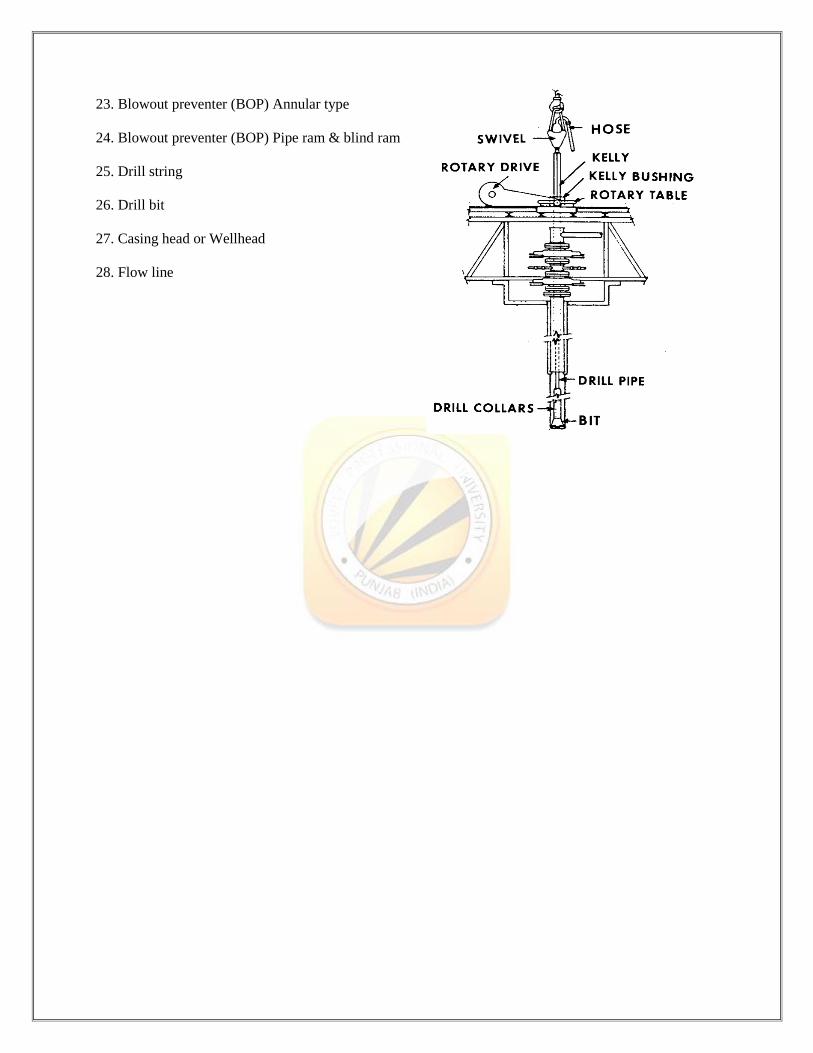
23. Blowout preventer (BOP) Annular type
24. Blowout preventer (BOP) Pipe ram & blind ram
25. Drill string
26. Drill bit
27. Casing head or Wellhead
28. Flow line
DESCRIPTION OF VARIOUS MECHANICAL COMPONENTS
1. MUD TANK
A mud tank is an open-top container, typically made of square steel tube and steel plate, to store drilling
fluid on a drilling rig. They are also called mud pits, because they used to be nothing more than pits dug
out of the earth.
Mud tanks play an important role in solids control system. It is the base of solids control equipments, and
also the carrier of drilling fluids. Solids control equipments that are all mounted on the top of mud tanks
include the followings:
Shale Shaker
Vacuum Degasser
Desander
Desilter
Centrifuge
Mud Agitator
Vertical slurry pump
Drilling fluids flow into the shale shaker directly after it returns to the surface of the well, and the solids
that are removed by the screen would be discharged out of the tank, and the drilling fluids with smaller
solids would flow through the screen into mud tank for further purification. A centrifugal pump would
suck the shaker-treated fluids up to the desilter or mud cleaner for further purification. And vertical slurry
pump is used to pump the drilling fluids up to the centrifuge, and mud pump would pump the drilling
fluids from mud tank into the borehole after it is treated by centrifuge. And the circulation system would
continue.
The number of the mud tanks that are needed on the drilling rig depends on the depth of the well, and also
the mud demands of drilling. Normally the shale shaker and vacuum degasser and desander are mounted
together on the same mud tank as the first tank at the oilfield, while desilter and centrifuge on the second
tank. Also the drilling rig has other different tank as reserve tank, emergency tank, etc.
Mud tank is an important part in the solids control system. Based on functions, mud tank includes:- Trip tank
Settling tank
Suction tank
Intermediate tank
Reserve tank
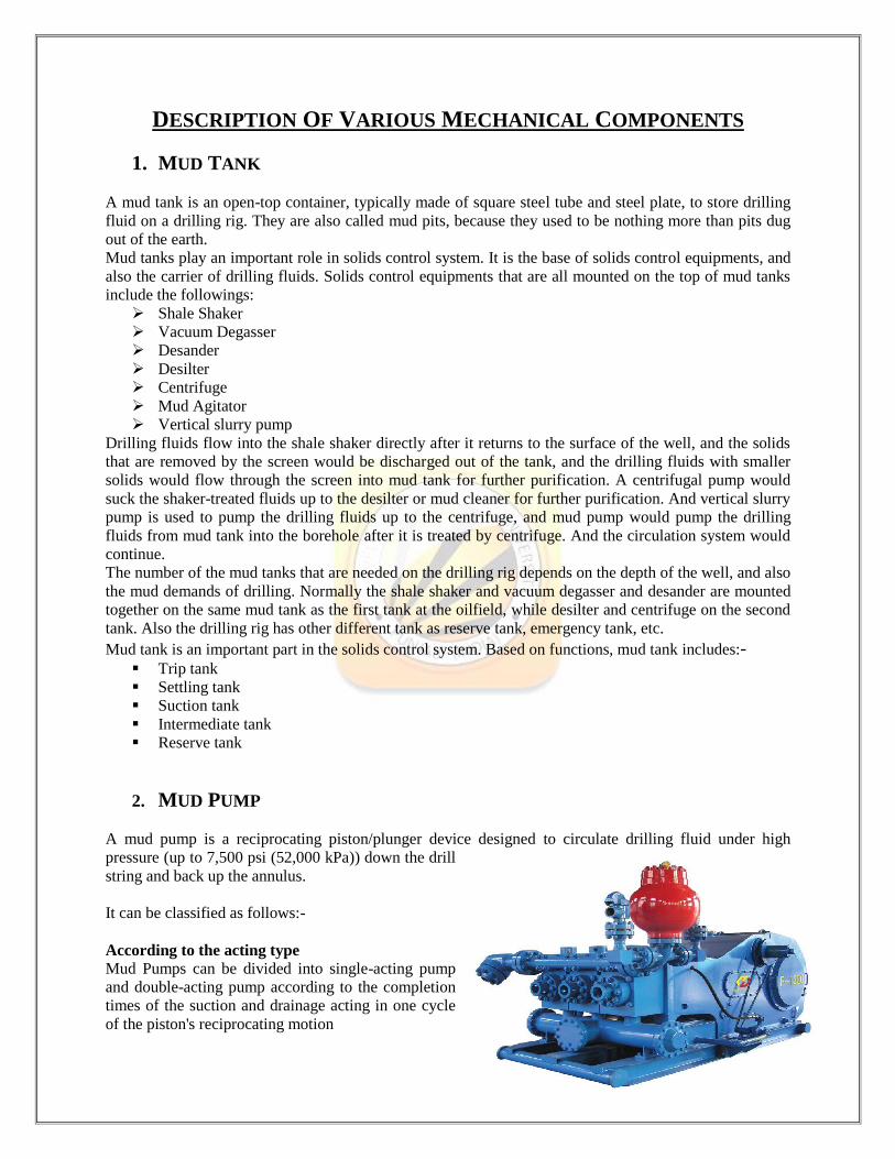
2. MUD PUMP
A mud pump is a reciprocating piston/plunger device designed to circulate drilling fluid under high
pressure (up to 7,500 psi (52,000 kPa)) down the drill
string and back up the annulus.
It can be classified as follows:-
According to the acting type
Mud Pumps can be divided into single-acting pump
and double-acting pump according to the completion
times of the suction and drainage acting in one cycle
of the piston's reciprocating motion
According to the quantity of liners (piston/plunger)
Mud Pumps come in a variety of sizes and configurations but for the typical petroleum drilling rig, the
triplex (three piston/plunger) Mud Pump is the pump of choice. Duplex Mud Pumps (two piston/plungers)
have generally been replaced by the triplex pump, but are still common in developing countries. Two later
developments are the hex pump with six vertical pistons/plungers, and various quintuplex's with five
horizontal piston/plungers. The advantages that these new pumps have over convention triplex pumps is a
lower mud noise which assists with better MWD and LWD retrieval.
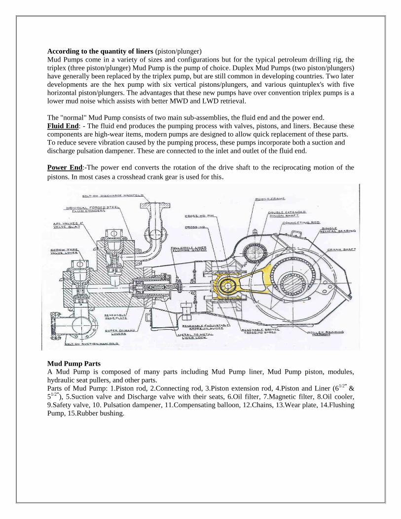
The "normal" Mud Pump consists of two main sub-assemblies, the fluid end and the power end.
Fluid End: - The fluid end produces the pumping process with valves, pistons, and liners. Because these
components are high-wear items, modern pumps are designed to allow quick replacement of these parts.
To reduce severe vibration caused by the pumping process, these pumps incorporate both a suction and
discharge pulsation dampener. These are connected to the inlet and outlet of the fluid end.
Power End:-The power end converts the rotation of the drive shaft to the reciprocating motion of the
pistons. In most cases a crosshead crank gear is used for this.
Mud Pump Parts
A Mud Pump is composed of many parts including Mud Pump liner, Mud Pump piston, modules,
hydraulic seat pullers, and other parts.
Parts of Mud Pump: 1.Piston rod, 2.Connecting rod, 3.Piston extension rod, 4.Piston and Liner (61/2”
&
51/2”
), 5.Suction valve and Discharge valve with their seats, 6.Oil filter, 7.Magnetic filter, 8.Oil cooler,
9.Safety valve, 10. Pulsation dampener, 11.Compensating balloon, 12.Chains, 13.Wear plate, 14.Flushing
Pump, 15.Rubber bushing.
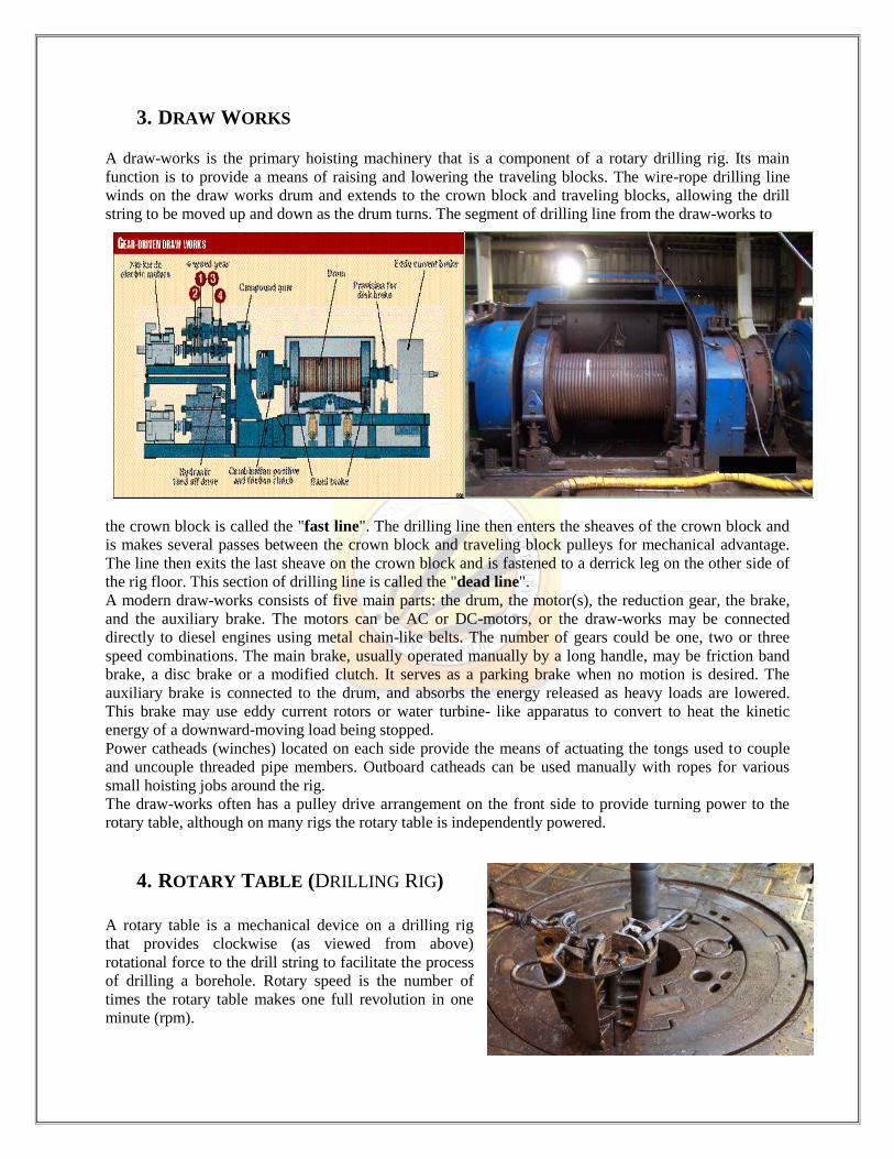
3. DRAW WORKS A draw-works is the primary hoisting machinery that is a component of a rotary drilling rig. Its main
function is to provide a means of raising and lowering the traveling blocks. The wire-rope drilling line
winds on the draw works drum and extends to the crown block and traveling blocks, allowing the drill
string to be moved up and down as the drum turns. The segment of drilling line from the draw-works to
the crown block is called the "fast line". The drilling line then enters the sheaves of the crown block and
is makes several passes between the crown block and traveling block pulleys for mechanical advantage.
The line then exits the last sheave on the crown block and is fastened to a derrick leg on the other side of
the rig floor. This section of drilling line is called the "dead line". A modern draw-works consists of five main parts: the drum, the motor(s), the reduction gear, the brake,
and the auxiliary brake. The motors can be AC or DC-motors, or the draw-works may be connected
directly to diesel engines using metal chain-like belts. The number of gears could be one, two or three
speed combinations. The main brake, usually operated manually by a long handle, may be friction band
brake, a disc brake or a modified clutch. It serves as a parking brake when no motion is desired. The
auxiliary brake is connected to the drum, and absorbs the energy released as heavy loads are lowered.
This brake may use eddy current rotors or water turbine- like apparatus to convert to heat the kinetic
energy of a downward-moving load being stopped.
Power catheads (winches) located on each side provide the means of actuating the tongs used to couple
and uncouple threaded pipe members. Outboard catheads can be used manually with ropes for various
small hoisting jobs around the rig.
The draw-works often has a pulley drive arrangement on the front side to provide turning power to the
rotary table, although on many rigs the rotary table is independently powered.
4. ROTARY TABLE (DRILLING RIG)
A rotary table is a mechanical device on a drilling rig
that provides clockwise (as viewed from above)
rotational force to the drill string to facilitate the process
of drilling a borehole. Rotary speed is the number of
times the rotary table makes one full revolution in one
minute (rpm).

Most rotary tables are chain driven. These chains resemble very large bicycle chains. The chains require
constant oiling to prevent burning and seizing. Virtually all rotary tables are equipped with a rotary lock'.
Engaging the lock can either prevent the rotary from turning in one particular direction, or from turning at
all. This is commonly used by crews in lieu of using a second pair of tongs to makeup or break out pipe.
The rotary bushings are located at the center of the rotary table. These can generally be removed in two
separate pieces to facilitate large items, i.e. drill bits, to pass through the rotary table. The large gap in the
center of the rotary bushings is referred to as the "bowl" due to its appearance. The bowl is where the
slips are set to hold up the drill string during connections and pipe trips as well as the point the drill string
passes through the floor into the wellbore. The rotary bushings connect to the kelly bushings to actually
induce the spin required for drilling.
5. DRILLING MUD CENTRIFUGAL PUMP
Centrifugal pumps are a sub-class of dynamic axis symmetric work absorbing turbo machinery. Centrifugal pumps are used to transport fluids by the conversion of rotational kinetic energy to the
hydrodynamic energy of the fluid flow. The rotational energy typically comes from an engine or electric
motor. The fluid enters the pump impeller along or near to the rotating axis and is accelerated by the
impeller, flowing radially outward into a diffuser or volute chamber (casing), from where it exits.
Common uses include water, sewage, petroleum and petrochemical pumping. The reverse function of the
centrifugal pump is a water turbine converting potential energy of water pressure into mechanical
rotational energy.
Applications of Drilling Mud Centrifugal Pump: - Drilling mud centrifugal pump is used for transporting
drilling fluids. It can be used as oilfield drilling feeding centrifugal pump for drilling mud desander,
drilling fluids desilter, or used as mixing pump for jet mud mixer. Also it can be used as trip pump and
supercharging pump for drilling rig mud pump.
Parts of Centrifugal Pump: - 1.Casing (6” *8” *14”), 2.Impeller, 3.Shaft, 4.Wear plate, 5.Vane,
6.Discharge Nozzle, 7.Bearing Housing
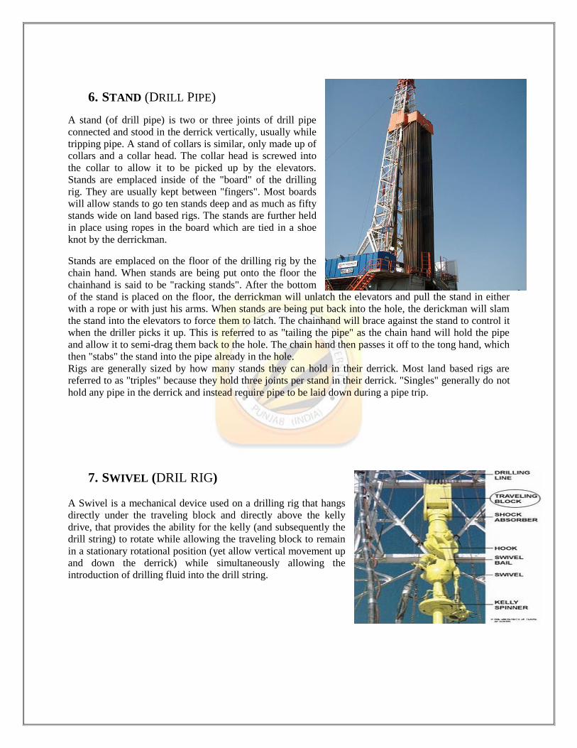
6. STAND (DRILL PIPE)
A stand (of drill pipe) is two or three joints of drill pipe
connected and stood in the derrick vertically, usually while
tripping pipe. A stand of collars is similar, only made up of
collars and a collar head. The collar head is screwed into
the collar to allow it to be picked up by the elevators.
Stands are emplaced inside of the "board" of the drilling
rig. They are usually kept between "fingers". Most boards
will allow stands to go ten stands deep and as much as fifty
stands wide on land based rigs. The stands are further held
in place using ropes in the board which are tied in a shoe
knot by the derrickman.
Stands are emplaced on the floor of the drilling rig by the
chain hand. When stands are being put onto the floor the
chainhand is said to be "racking stands". After the bottom
of the stand is placed on the floor, the derrickman will unlatch the elevators and pull the stand in either
with a rope or with just his arms. When stands are being put back into the hole, the derickman will slam
the stand into the elevators to force them to latch. The chainhand will brace against the stand to control it
when the driller picks it up. This is referred to as "tailing the pipe" as the chain hand will hold the pipe
and allow it to semi-drag them back to the hole. The chain hand then passes it off to the tong hand, which
then "stabs" the stand into the pipe already in the hole.
Rigs are generally sized by how many stands they can hold in their derrick. Most land based rigs are
referred to as "triples" because they hold three joints per stand in their derrick. "Singles" generally do not
hold any pipe in the derrick and instead require pipe to be laid down during a pipe trip.
7. SWIVEL (DRIL RIG)
A Swivel is a mechanical device used on a drilling rig that hangs
directly under the traveling block and directly above the kelly
drive, that provides the ability for the kelly (and subsequently the
drill string) to rotate while allowing the traveling block to remain
in a stationary rotational position (yet allow vertical movement up
and down the derrick) while simultaneously allowing the
introduction of drilling fluid into the drill string.
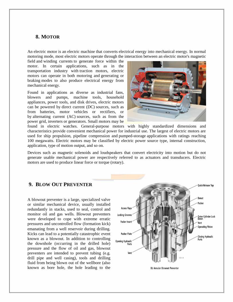
8. MOTOR
An electric motor is an electric machine that converts electrical energy into mechanical energy. In normal
motoring mode, most electric motors operate through the interaction between an electric motor's magnetic
field and winding currents to generate force within the
motor. In certain applications, such as in the
transportation industry with traction motors, electric
motors can operate in both motoring and generating or
braking modes to also produce electrical energy from
mechanical energy.
Found in applications as diverse as industrial fans,
blowers and pumps, machine tools, household
appliances, power tools, and disk drives, electric motors
can be powered by direct current (DC) sources, such as
from batteries, motor vehicles or rectifiers, or
by alternating current (AC) sources, such as from the
power grid, inverters or generators. Small motors may be
found in electric watches. General-purpose motors with highly standardized dimensions and
characteristics provide convenient mechanical power for industrial use. The largest of electric motors are
used for ship propulsion, pipeline compression and pumped-storage applications with ratings reaching
100 megawatts. Electric motors may be classified by electric power source type, internal construction,
application, type of motion output, and so on.
Devices such as magnetic solenoids and loudspeakers that convert electricity into motion but do not
generate usable mechanical power are respectively referred to as actuators and transducers. Electric
motors are used to produce linear force or torque (rotary).
9. BLOW OUT PREVENTER
A blowout preventer is a large, specialized valve
or similar mechanical device, usually installed
redundantly in stacks, used to seal, control and
monitor oil and gas wells. Blowout preventers
were developed to cope with extreme erratic
pressures and uncontrolled flow (formation kick)
emanating from a well reservoir during drilling.
Kicks can lead to a potentially catastrophic event
known as a blowout. In addition to controlling
the downhole (occurring in the drilled hole)
pressure and the flow of oil and gas, blowout
preventers are intended to prevent tubing (e.g.
drill pipe and well casing), tools and drilling
fluid from being blown out of the wellbore (also known as bore hole, the hole leading to the

reservoir) when a blowout threatens. Blowout preventers
are critical to the safety of crew, rig (the equipment
system used to drill a wellbore) and environment, and to
the monitoring and maintenance of well integrity; thus
blowout preventers are intended to provide fail safety to
the systems that include them.
The term BOP (pronounced B-O-P, not "bop") is used in
oilfield vernacular to refer to blowout preventers. The
abbreviated term preventer, usually prefaced by a type
(e.g. ram preventer), is used to refer to a single blowout
preventer unit. A blowout preventer may also simply be
referred to by its type (e.g. ram).
The terms blowout preventer, blowout preventer stack
and blowout preventer system are commonly used
interchangeably and in a general manner to describe an
assembly of several stacked blowout preventers of
varying type and function, as well as auxiliary
components. A typical subsea deepwater blowout
preventer system includes components such as electrical and hydraulic lines, control pods, hydraulic
accumulators, test valve, kill and choke lines and valves, riser joint, hydraulic connectors, and a support
frame.
Two categories of blowout preventer are most prevalent: ram and annular. BOP stacks frequently utilize
both types, typically with at least one annular BOP stacked above several ram BOPs.
Blowout preventers are used at land and oil platform offshore rigs, and subsea. Land and subsea BOPs are
secured to the top of the wellbore, known as the wellhead. BOPs on offshore rigs are mounted below the
rigdeck.
10. CROWN BLOCK A crown block is the stationary section of a block and tackle that
contains a set of pulleys or sheaves through which the drill line (wire
rope) is threaded or reeved and is opposite and above the traveling
block.
The combination of the traveling block, crown block and wire rope
drill line gives the ability to lift weights in the hundreds of thousands
of pounds. On larger drilling rigs, when raising and lowering the
derrick, line tensions over a million pounds are not unusual.
11. DRILL BIT
A Drill bit is a device attached to the end of the
drill string that breaks apart, cuts or crushes the
rock formations when drilling a wellbore, such as
those drilled to extract water, gas, or oil.
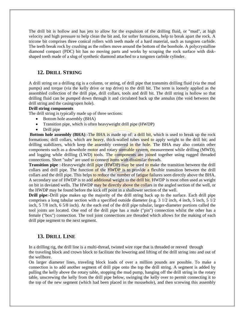
The drill bit is hollow and has jets to allow for the expulsion of the drilling fluid, or "mud", at high
velocity and high pressure to help clean the bit and, for softer formations, help to break apart the rock. A
tricone bit comprises three conical rollers with teeth made of a hard material, such as tungsten carbide.
The teeth break rock by crushing as the rollers move around the bottom of the borehole. A polycrystalline
diamond compact (PDC) bit has no moving parts and works by scraping the rock surface with disk-
shaped teeth made of a slug of synthetic diamond attached to a tungsten carbide cylinder.
12. DRILL STRING
A drill string on a drilling rig is a column, or string, of drill pipe that transmits drilling fluid (via the mud
pumps) and torque (via the kelly drive or top drive) to the drill bit. The term is loosely applied as the
assembled collection of the drill pipe, drill collars, tools and drill bit. The drill string is hollow so that
drilling fluid can be pumped down through it and circulated back up the annulus (the void between the
drill string and the casing/open hole).
Drill string components
The drill string is typically made up of three sections:
Bottom hole assembly (BHA)
Transition pipe, which is often heavyweight drill pipe (HWDP)
Drill pipe
Bottom hole assembly (BHA):-The BHA is made up of: a drill bit, which is used to break up the rock
formations; drill collars, which are heavy, thick-walled tubes used to apply weight to the drill bit; and
drilling stabilizers, which keep the assembly centered in the hole. The BHA may also contain other
components such as a downhole motor and rotary steerable system, measurement while drilling (MWD),
and logging while drilling (LWD) tools. The components are joined together using rugged threaded
connections. Short "subs" are used to connect items with dissimilar threads.
Transition pipe :-Heavyweight drill pipe (HWDP) may be used to make the transition between the drill
collars and drill pipe. The function of the HWDP is to provide a flexible transition between the drill
collars and the drill pipe. This helps to reduce the number of fatigue failures seen directly above the BHA.
A secondary use of HWDP is to add additional weight to the drill bit. HWDP is most often used as weight
on bit in deviated wells. The HWDP may be directly above the collars in the angled section of the well, or
the HWDP may be found before the kick off point in a shallower section of the well.
Drill pipe:-Drill pipe makes up the majority of the drill string back up to the surface. Each drill pipe
comprises a long tubular section with a specified outside diameter (e.g. 3 1/2 inch, 4 inch, 5 inch, 5 1/2
inch, 5 7/8 inch, 6 5/8 inch). At the each end of the drill pipe tubular, larger-diameter portions called the
tool joints are located. One end of the drill pipe has a male ("pin") connection whilst the other has a
female ("box") connection. The tool joint connections are threaded which allows for the making of each
drill pipe segment to the next segment.
13. DRILL LINE
In a drilling rig, the drill line is a multi-thread, twisted wire rope that is threaded or reeved through
the traveling block and crown block to facilitate the lowering and lifting of the drill string into and out of
the wellbore.
On larger diameter lines, traveling block loads of over a million pounds are possible. To make a
connection is to add another segment of drill pipe onto the top the drill string. A segment is added by
pulling the kelly above the rotary table, stopping the mud pump, hanging off the drill string in the rotary
table, unscrewing the kelly from the drill pipe below, swinging the kelly over to permit connecting it to
the top of the new segment (which had been placed in the mousehole), and then screwing this assembly
into the top of the existing drill string. Mud circulation is resumed, and the drill string is lowered into the
hole until the bit takes weight at the bottom of the hole. Drilling then resumes.
14. DRILLING FLUID
In geotechnical engineering, drilling fluid is used to aid the drilling of boreholes into the earth. Often used
while drilling oil and natural gas wells and on exploration drilling rigs, drilling fluids are also used for
much simpler boreholes, such as water wells.
Liquid drilling fluid is often called drilling mud. The three main categories of drilling fluids are water-
based muds (which can be dispersed and non-dispersed), non-aqueous muds, usually called oil-based
mud, and gaseous drilling fluid, in which a wide range of gases can be used.
Functions : -
Remove cuttings from well
Suspend and release cuttings
Control formation pressures
Seal permeable formations
Maintain wellbore stability
Minimizing formation damage
Cool, lubricate, and support the bit and drilling assembly
Transmit hydraulic energy to tools and bit
Ensure adequate formation evaluation
Control corrosion (in acceptable level)
Facilitate cementing and completion
Minimize impact on environment
Three factors affecting drilling fluid performance are: -
The change of drilling fluid viscosity
The change of drilling fluid density
The change of mud Ph
15. KELLY DRIVE
A kelly drive refers to a type of well drilling device on an oil or gas drilling rig that employs a section of
pipe with a polygonal (three-, four-, six-, or eight-sided) or splined outer surface, which passes through
the matching polygonal or splined kelly (mating) bushing and rotary table. This bushing is rotated via the
rotary table and thus the pipe and the attached drill string turn while the polygonal pipe is free to slide
vertically in the bushing as the bit digs the well deeper. When drilling, the drill bit is attached at the end
of the drill string and thus the kelly drive provides the means to turn the bit (assuming that a downhole
motor is not being used).
The kelly is the polygonal tubing and the kelly bushing is the mechanical device that turns the kelly when
rotated by the rotary table. Together they are referred to as a kelly drive. The upper end of the kelly is
screwed into the swivel, using a left-hand thread to preclude loosening from the right-hand torque applied
below. The kelly typically is about 10 ft (3 m) longer than the drill pipe segments, thus leaving a portion
of newly drilled hole open below the bit after a new length of pipe has been added ("making a
connection") and the drill string has been lowered until the kelly bushing engages again in the rotary
table.
The kelly hose is the flexible, high-pressure hose connected from the standpipe to a gooseneck pipe on a
swivel above the kelly and allows the free vertical movement of the kelly while facilitating the flow of the
drilling fluid down the drill string. It generally is of steel-reinforced rubber construction but also
assemblies of Chiksan steel pipe and swivels are used.
The name kelly is derived from the machine shop in which the first kelly was made. It was located in a
town formerly named Kellysburg, Pennsylvania.
16. KELLY HOSE
A Kelly hose (also known as a mud hose or rotary hose) is a flexible, steel reinforced, high pressure hose
that connects the standpipe to the kelly (or more specifically to the goose-neck on the swivel above the
kelly) and allows free vertical movement of the kelly while facilitating the flow of drilling fluid through
the system and down the drill string.
17. PIPE RACK
Structural steel pipe racks typically support pipes, power cables and instrument cable trays in
petrochemical, chemical and power plants. Occasionally, pipe racks may also support mechanical
equipment, vessels and valve access platforms. Main pipe racks generally transfer material between
equipment and storage or utility areas.
Storage racks found in warehouses are not pipe racks, even if they store lengths of pipe.
A pipe rack is the main artery of a process unit. Pipe racks carry process and utility piping and may also
include instrument and cable trays as well as equipment mounted over all of these.
Pipe racks consist of a series of transverse bents that run along the length of the pipe system, spaced at
uniform intervals typically around 20 ft. To allow maintenance access under the pipe rack, the transverse
bents are typically moment frames. Transverse bents are typically connected with longitudinal struts.
18. RIG STANDPIPE
A rig standpipe is a solid metal pipe attached to the side of a drilling rig's derrick that is a part of its
drilling mud system. It is used to conduct drilling fluid from the mud pumps to the kelly hose. Bull plugs,
pressure transducers and valves are found on the rig standpipe.
19. TRAVELLING BLOCK
A traveling block is the freely moving section of a block and tackle that contains a set of pulleys or
sheaves through which the drill line (wire rope) is threaded or reeved and is opposite (and under) the
crown block (the stationary section). The combination of the traveling block, crown block and wire rope
drill line gives the ability to lift weights in the hundreds of thousands of pounds. On larger drilling rigs,
when raising and lowering the derrick, line tensions over a million pounds are not unusual.

20. FLOW LINE
A flow line, used on a drilling rig, is a large diameter pipe (typically a section of casing) that is connected
to the bell nipple (under the drill floor) and extends to the possum belly (on the mud tanks) and acts as a
return line, (for the drilling fluid as it comes out of the hole), to the mud tanks.
21. BELL NIPPLE
A Bell nipple is a section of large diameter pipe fitted to the top of the blowout preventers that the flow
line attaches to via a side outlet, to allow the drilling fluid to flow back over the shale shakers to the mud
tanks.
22. DRILL FLOOR
The Drill Floor is the heart of any drilling rig. This is the area
where the drill string begins its trip into the earth. It is
traditionally where joints of pipe are assembled, as well as the
BHA (bottom hole assembly), drilling bit, and various other tools.
This is the primary work location for roughnecks and the driller.
The drill floor is located directly under the derrick.
The floor is a relatively small work area in which the rig crew
conducts operations, usually adding or removing drill pipe to or
from the drill string. The rig floor is the most dangerous location
on the rig because heavy iron is moved around there. Drill string
connections are made or broken on the drill floor, and the driller's
console for controlling the major components of the rig are
located there. Attached to the rig floor is a small metal room, the
doghouse, where the rig crew can meet, take breaks and take
refuge from the elements during idle times.
23. MONKEY BOARD Monkey board is the catwalk along the side of the derrick (usually about 35 or 40 feet above the "floor").
The monkey board is where the derrick man works while "tripping" pipe.
24. GOOSE-NECK Goose-neck is a thick metal elbow connected to the swivel and standpipe that supports the weight of and
provides a downward angle for the kelly hose to hang from.

25. VIBRATING HOSE Vibrating hose is a flexible, high pressure hose (similar to the kelly
hose) that connects the mud pump to the stand pipe. It is called the
vibrating hose because it tends to vibrate and shake (sometimes
violently) due to its close proximity to the mud pumps.
26. AGITATOR An agitator is a device or mechanism to put something into motion by shaking or stirring. There are three
main types of agitation machines the washing machine agitator, which rotates back and forth; the
magnetic agitator, which contains a magnetic bar which rotates about a magnetic field; manual agitation,
such as with a stirring rod.
27. MUD MOTOR A mud motor (or drilling motor) is a progressive
cavity positive displacement pump (PCPD) placed in
the drill string to provide additional power to the bit
while drilling. The PCPD pump uses drilling
fluid (commonly referred to as drilling mud, or just
mud) to create eccentric motion in the power section
of the motor which is transferred as concentric power
to the drill bit (well). The mud motor uses different
rotor and stator configurations to provide optimum
performance for the desired drilling operation,
typically increasing the number of lobes and length of
power assembly for greater horsepower. In certain
applications, compressed air, or other gas, can be used
for mud motor input power. Normal rotation of the bit while using a mud motor can be from 60 rpm, to
over 100 rpm.
Basic principle :- Based on the principle developed by Rene Moineau, the theory states that a helical
rotor with one or more lobes will rotate eccentrically when the stator contains more lobes than the rotor.
The flow of the fluid transmits power allowing the assembly to rotate and turn the bit.
Advantages :- Extremely hard rock formations can be drilled with motors using diamond or PDC bits.
High penetration rates can be achieved since rotation speeds are high. Will allow circulation of the
borehole regardless of the horsepower or torque produced by the motor.

MUD CLEANING UNIT
1. SHALE SHAKER
Shale shakers are components of drilling equipment used in many industries, such as coal cleaning,
mining, oil and gas drilling. They are the first phase of a solids control system on a drilling rig, and are
used to remove large solids (cuttings) from the drilling fluid
("Mud").
Drilling fluids are integral to the drilling process and, among
other functions, serve to lubricate and cool the drill bit as
well as convey the drilled cuttings away from the bore hole.
These fluids are a mixture of various chemicals in water or
oil based solution and can be very expensive to make. For
both environmental reasons and to reduce the cost of drilling
operations, drilling fluid losses are minimized by stripping
them away from the drilled cuttings before the cuttings are
disposed of. This is done using a multitude of specialized
machines and tanks.
Shale shakers are the primary solids separation tool on a rig.
After returning to the surface of the well the used drilling fluid flows directly to the shale shakers where it
begins to be processed. Once processed by the shale shakers the drilling fluid is deposited into the mud
tanks where other solid control equipment begins to remove the finer solids from it. The solids removed

by the shale shaker are discharged out of the discharge port into a separate holding tank where they await
further treatment or disposal.
Shale shakers are considered by most of the drilling industry to be the most important device in the solid
control system as the performance of the successive equipment directly relates to the cleanliness of the
treated drilling fluid.
Mudloggers usually go out and check the shakers for rock samples that have circulated from bottom.
They separate the rock from the drilling fluid and take it into an onsite lab where they dry out the samples
and label them according to depth. They then look at the samples and analyze what kind of rock they have
at a certain depth. This helps determines what depth that type of rock was encountered.
2. DESANDER
Desanders are solid control equipment with a set of hydrocyclones that separate sand and silt from the
drilling fluids in drilling rigs. Desanders are installed on top of the mud tank following the shale shaker
and the degasser, but before the desilter. Desander removes the abrasive solids from the drilling fluids
which cannot be removed by shakers. Normally the solids diameter for desander to be separated would be
45~74μm, and 15~44μm for desilter.
A centrifugal pump is used to pump the drilling fluids from mud tank into the set of hydrocyclones.
Solids control Desanders have moving parts. The larger the internal diameter of the desander is, the greater the amount
of drilling fluids it is able to process and the larger the size of the solids removed. A desander with a (10
inches (250 mm) cone) is able to remove 50% of solids within the 40-50 μm (micrometer) range at a flow
rate of 500 US gallons per minute (32 L/s), while a desilter (4 inches (100 mm) Cone) is able to remove
50% of solids within the 15-20 μm range at a flow rate of 60 US gallons per minute (3.8 L/s). Micro-fine
separators are able to remove 50% of solids within the 10-15 μm range at a flow rate of 15 US gallons per
minute (0.95 L/s). A desander is typically positioned next-to-last in the arrangement of solids control
equipment, with a decanter centrifuge as the subsequent processing unit. Desanders are preceded by gas
busters, gumbo removal equipment (if utilized), shale shaker, mud cleaner (if utilized) and a vacuum
degasser. Desanders are widely used in oilfield drilling. Practice has proved that hydrocyclone desanders
are economic and effective equipment.
3. DESILTER
Desilter is the third stage solids control and fourth stage drilling mud cleaning equipment in the drilling
fluids recycling system. GN Desilter commonly adapts 4” cyclone which could separate the solid phase
particles with size of 15-25 microns. GN Desilter is designed 2 options of with and without underflow
screen for customers’ requirement.
The desilter with underflow shaker is also called Mini cleaner which is applicable for both weighted and
unweighted drilling mud, while traditional desander no underflow vibrating screen only for unweighted
drilling fluids. And comparing with large size desander and desilter assembly, the Mini Desander is cost-
effective. For compact mud system used in HDD, CBM, water well drilling and mining project, Mini
desilter cleaner is an ideal choice.
4. DEGASSER A degasser is a device used in drilling to remove gasses from drilling fluid which could otherwise
form bubbles. For small amount of entrained gas in a drilling fluid, the degasser can play a major role of
removing small bubbles that a liquid film has enveloped and entrapped. In order for it to be released and
break out the air and gas such as methane, H2S and CO2 from the mud to the surface, the drilling fluid
must pass degassing technique and it can be accomplished by the equipment called degasser which is also
a major part of a mud systems.
CASING
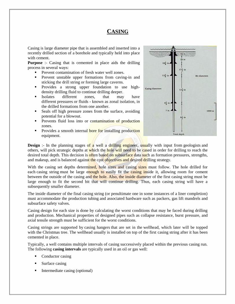
Casing is large diameter pipe that is assembled and inserted into a
recently drilled section of a borehole and typically held into place
with cement.
Purpose :- Casing that is cemented in place aids the drilling
process in several ways:
Prevent contamination of fresh water well zones.
Prevent unstable upper formations from caving-in and
sticking the drill string or forming large caverns.
Provides a strong upper foundation to use high-
density drilling fluid to continue drilling deeper.
Isolates different zones, that may have
different pressures or fluids - known as zonal isolation, in
the drilled formations from one another.
Seals off high pressure zones from the surface, avoiding
potential for a blowout.
Prevents fluid loss into or contamination of production
zones.
Provides a smooth internal bore for installing production
equipment.
Design :- In the planning stages of a well a drilling engineer, usually with input from geologists and
others, will pick strategic depths at which the hole will need to be cased in order for drilling to reach the
desired total depth. This decision is often based on subsurface data such as formation pressures, strengths,
and makeup, and is balanced against the cost objectives and desired drilling strategy.
With the casing set depths determined, hole sizes and casing sizes must follow. The hole drilled for
each casing string must be large enough to easily fit the casing inside it, allowing room for cement
between the outside of the casing and the hole. Also, the inside diameter of the first casing string must be
large enough to fit the second bit that will continue drilling. Thus, each casing string will have a
subsequently smaller diameter.
The inside diameter of the final casing string (or penultimate one in some instances of a liner completion)
must accommodate the production tubing and associated hardware such as packers, gas lift mandrels and
subsurface safety valves.
Casing design for each size is done by calculating the worst conditions that may be faced during drilling
and production. Mechanical properties of designed pipes such as collapse resistance, burst pressure, and
axial tensile strength must be sufficient for the worst conditions.
Casing strings are supported by casing hangers that are set in the wellhead, which later will be topped
with the Christmas tree. The wellhead usually is installed on top of the first casing string after it has been
cemented in place.
Typically, a well contains multiple intervals of casing successively placed within the previous casing run.
The following casing intervals are typically used in an oil or gas well:
Conductor casing
Surface casing
Intermediate casing (optional)
Production casing
Production liner
The conductor casing serves as a support during drilling operations, to flow back returns during drilling
and cementing of the surface casing, and to prevent collapse of the loose soil near the surface. It can
normally vary from sizes such as 18" to 30".
The purpose of surface casing is to isolate freshwater zones so that they are not contaminated during
drilling and completion. Surface casing is the most strictly regulated due to these environmental concerns,
which can include regulation of casing depth and cement quality. A typical size of surface casing is 13⅜
inches.
Intermediate casing may be necessary on longer drilling intervals where necessary drilling mud weight to
prevent blowouts may cause a hydrostatic pressure that can fracture shallower or deeper formations.
Casing placement is selected so that the hydrostatic pressure of the drilling fluid remains between In order
to reduce cost, a liner may be used which extends just above the shoe (bottom) of the previous casing
interval and hung off downhole rather than at the surface. It may typically be 7", although many liners
match the diameter of the production tubing.
Few wells actually produce through casing, since producing fluids can corrode steel or form deposits such
as asphaltenes or paraffin waxes and the larger diameter can make flow unstable. Production tubing is
therefore installed inside the last casing string and the tubing annulus is usually sealed at the bottom of
the tubing by a packer. Tubing is easier to remove for maintenance, replacement, or for various types of
workover operations. It is significantly lighter than casing and does not require a drilling rig to run in and
out of hole; smaller "service rigs" are used for this purpose.
Cementing is performed by circulating a cement slurry through the inside of the casing and out into the
annulus through the casing shoe at the bottom of the casing string. In order to precisely place the cement
slurry at a required interval on the outside of the casing, a plug is pumped with a displacement fluid
behind the cement slurry column, which "bumps" in the casing shoe and prevents further flow of fluid
through the shoe. This bump can be seen at surface as a pressure spike at the cement pump. To prevent
the cement from flowing back into the inside of the casing, a float collar above the casing shoe acts as
a check valve and prevents fluid from flowing up through the shoe from the annulus.
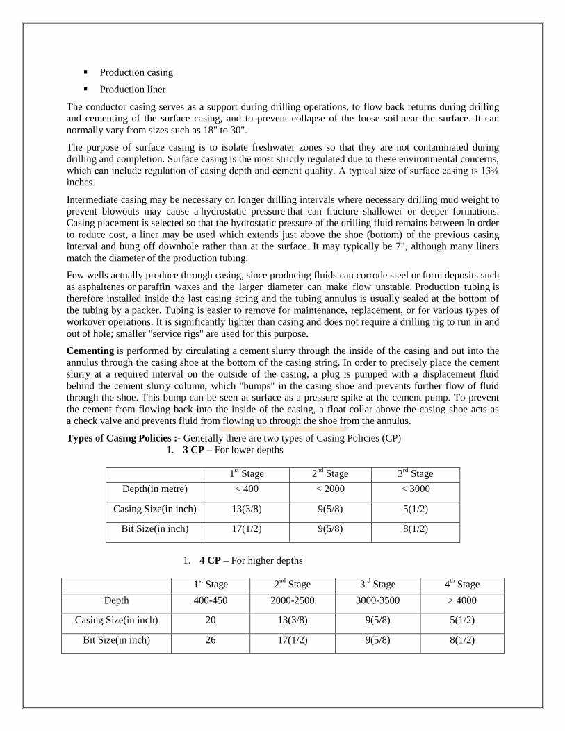
Types of Casing Policies :- Generally there are two types of Casing Policies (CP)
1. 3 CP – For lower depths
1st Stage 2
nd Stage 3
rd Stage
Depth(in metre) < 400 < 2000 < 3000
Casing Size(in inch) 13(3/8) 9(5/8) 5(1/2)
Bit Size(in inch) 17(1/2) 9(5/8) 8(1/2)
1. 4 CP – For higher depths
1st Stage 2
nd Stage 3
rd Stage 4
th Stage
Depth 400-450 2000-2500 3000-3500 > 4000
Casing Size(in inch) 20 13(3/8) 9(5/8) 5(1/2)
Bit Size(in inch) 26 17(1/2) 9(5/8) 8(1/2)

HOW A WELL IS DRILLED ON LAND:
Step 1: Digging a Cellar
On land, a majority of wells begin with digging a cellar from three to fifteen feet in depth. The purpose of
a cellar is to align the production Christmas tree at ground level, providing easier access to the valves,
chokes, and other equipment.
Step 2: Running a Conductor Pipe
The first string of pipe used in a well is called the conductor pipe, or drive pipe. The pipe is usually 30-36
inches in diameter. A large diameter hole is drilled to a specified depth, usually one or two hundred feet,
and the pipe is driven into the ground.
Step 3: Connecting the BOP
An adapter flange, or drilling flange, is welded to the conductor pipe to connect a diverter system or a
blowout preventer system to control wellhead pressure.
Step 4: Running the Surface Pipe
A hole is drilled for the well’s first string of pipe, the surface pipe, and the pipe is run in the hole. There
may be several strings of pipe in a well, each run to a different depth. The number of strings is determined
by the number of zones being drilled through. These can include fresh water, salt water, and potential
production zones. Each zone is isolated, or cased off, until it is to be produced.
Step 5: Connecting the Surface Pipe
The surface pipe is cemented in place back to the surface. This holds the pipe in place and seals off the
zone. A cement plug is left in the pipe so that the BOP system may be disconnected safely. The BOP is
then removed from the adapter flange.
Step 6: Cutting the Conductor Pipe and Surface Casing The surface pipe is drained, the adapter flange (or drilling flange) is cut off, and both the conductor pipe
and the surface casing are cut to the proper height to allow the top of the completed wellhead to be at
ground level.
Step 7: Installing the Casing Head Housing and Base Plate The casing head housing is welded in place on the inside diameter and the outside diameter of the surface
casing. The housing is then tested to assure there are no leak paths in the welds.
Step 8: Installing the BOP System The BOP system is installed above the casing head housing and then tested. To test the BOP system, the
test plug is made up on the drill string and lowered through the BOP system onto the casing head bowl.
Pressure is applied from above the plug to test the BOP system
Step 9: Installing the Casing Head Wear Bushing A wear bushing is installed to protect the interior of the casing head from damage by drilling equipment.
Step 10: Installing the Intermediate String A hole is drilled for the intermediate string and the casing is run in the hole and cemented in place. A
cement plug is left in the intermediate casing, just as it was in the surface casing.
Step 11: Installing the Casing Hanger and Casing Spool The intermediate casing is suspended from the block above the rig floor, the BOP is picked up, and the
casing hanger is installed on top of the casing head. Holes are cut in the casing to allow the drilling fluids
to drain out of the casing riser. When the fluid has drained, the casing is cut off to the appropriate height
and the casing spool is installed.
Step 12: Installing the BOP System The BOP system is installed above the casing spool and then tested. To test the BOP system, the test plug
is made up on the drill string and lowered through the BOP system onto the casing head bowl. Pressure is
applied from above the plug to test the BOP system.
Step 13: Installing the Wear Bushing The wear bushing running tool is made up on the drill string and the wear bushing installed on the
running tool. The wear bushing is then lowered through the BOP system, until it rests in the casing spool
bowl, and then is locked into place. The running tool is removed and drilling resumes.
Step 14: Running the Production Casing String The production casing string is usually run to the total depth of the well. A hole is drilled for the
production casing and the casing is run in the hole and cemented into place. A cement plug is left in the
production casing, as in the previous steps.
Step 15: Installing the Casing Hanger and Tubing Spool The production casing is suspended from the elevators at the rig floor, the BOP is picked up, and the
production casing hanger is installed in the same way as the previous casing hanger. The tubing spool is
installed in the same way as the casing spool. After the spool has been installed, the seals and connections
are tested, and the BOP system is reinstalled.
Step 16: Running the Production Tubing The production tubing is installed inside the production casing. Unlike casing, the production tubing is
not cemented in the well so it may be removed later, if necessary
Step 17: Installing the Down hole Packer Assembly A down hole packer assembly (a type of seal assembly) is run and installed in the production casing to
seal the reservoir from all strings of pipe, except the production tubing.
Step 18: Installing the Tubing Hanger The tubing hanger is installed on the tubing at the rig floor, and then lowered into the bowl of the tubing
spool. The packer seals are tested, and a backpressure valve is installed in the tubing hanger so that the
BOP can be removed safely. After the valve has been installed the BOP is removed.
Step 19: Installing the Christmas Tree The production Christmas tree, sometimes called the flow assembly, controls the flow of the well. It is
made up of a seal flange, or tubing head adapter, a series of valves, and a choke. The valves are stacked
vertically and horizontally to provide backup should a valve fail. Each Christmas tree has at least one
actuated surface safety valve to shut down the well in an emergency and prevent damage to equipment
downstream. The Christmas tree is connected to a flow line, which transports the well’s fluid or gas.
The Christmas tree is oriented properly, picked up, lowered over the neck of the tubing hanger, and
connected to the tubing spool. The connections and seals are tested, and the well is now ready for
production testing.

REFERENCES
1. MD Totco Manuals
2. Wikipedia
3. Google
4. Sensor Manuals
5. National Oil Varco (nov.com)