oneac product selection guide - gryphon inc. sheets/935012e - product selection guid… · choose...
TRANSCRIPT

A H I G H E R L E V E L O F C O N F I D E N C E
O N E A C Product Se lect ion Guide

A H I G H E R L E V E L O F C O N F I D E N C E
Confidence in reliability
Those who depend upon electronic-based systems to conduct business, demand
confidence that problem power will not disrupt the performance of those systems.
ONEAC delivers that confidence. With a unique set of tools we’ve developed to
condition the electrical environment. To control it. Adapt it and back it up. And to
respond to it automatically when no one's around. Plus we provide our knowledge.
Knowledge of the potential problems inherent in the electrical environment... of
the impact on productivity, and profitability, those problems can have. And the
knowledge of what it takes to solve them.
A complete approach
Computers, medical instrumentation, telecommunications and manufacturing
systems, all rely on the performance of semiconductors. And the performance of
semiconductors relies on clean power — power free from all electrical interference.
To achieve it requires an interface that isolates semiconductors from the electrical
world they connect to.
This interface must limit both peak voltage (amplitude) and edge-speed
(frequency) of electrical transients. It must control the electrical environment
without introducing undesirable side effects. And convert a noisy safety ground to
a noise-free signal ground. These principles form the basis of ONEAC's innovative
technologies. Technologies that haven proven uniquely effective against all
conducted electrical disturbances.
A different kind of product
By any technical measure, ONEAC products set the performance standards for our
industry. But the only difference that matters to our customers is how well our
products do what we designed them to do — keep electronics operating reliably.
Even in the noisiest, most brutal electrical environments — environments where the
limitations of alternative products become painfully apparent. ONEAC delivers a
higher level of confidence for the people who choose us.
Making the world safe for electronics
How to use this selection guide
To Place Orders: TOLL FREE 800-327-8801, Ext. 1 EUROPE +44-(0)-1235-534721
U.S. 847-816-6000 EUROPE FAX +44-(0)-1235-534197
FAX 847-680-5124
We’ve designed this guide to make it simple for you to specify the right product for your application. Below is a listing of
the four product groups we manufacture. For each, we’ve described the type of protection provided.
1. Read the descriptions below to select the proper product group for your application.
2. Turn to the page indicated for detailed instructions that will guide you, step by step, through the process of specifying
the ONEAC model and part number best suited for the electronic equipment you wish to protect.
P O W E R C O N D I T I O N E R S P A G E 4
ONEAC power conditioners clean up contaminated power by removing power line noise, while protecting against
lightning, spikes, and transients. Used to safeguard sensitive microprocessor-based electronic equipment, they extend
equipment life and insure trouble-free operation.
C O N D I T I O N E D U P S S Y S T E M S P A G E 1 7
ONEAC conditioned uninterruptible power supply systems are power conditioners with batteries that provide back-up
power to ride through blackouts, brownouts and power line sags. Used to protect mission critical electronic components
such as network servers, and telephone system controllers, they prevent data loss, corruption, and protect
hardware against damage from all forms of power disturbances.
P O W E R M A N A G E M E N T A N D D I A G N O S T I C S O F T W A R E P A G E 2 4
ONEAC Interface Accessory Kits add intelligent features to ONEAC conditioned UPSs. Specify them to support network
communications, automated power fail response, power monitoring and remote management capabilities.
C O M M U N I C A T I O N L I N E P R O T E C T O R S P A G E 2 6
OnLine telephone and data line protectors shield voice and data switching equipment from the devastating effects of
overvoltage and overcurrent on telecommunications lines. Incorporating three stages of protection — solid state, PTC’s
and ONEAC’s patented transient filtering — they eliminate damaging high frequency transients that pass through
conventional products.
K E Y T O C O N N E C T O R S P A G E 3 0
T E C H N I C A L S U P P O R T P O L I C Y P A G E 3 1
W A R R A N T Y P A G E 3 1

C H O O S E A N O N E A C P R O D U C T S E R I E S
D E T E R M I N E Y O U R E Q U I P M E N T ’ S P O W E R R E Q U I R E M E N T S
Power Conditioner Selection Guide
4
O N E A C P O W E R C O N D I T I O N E R S
The greatest threats to the reliability of semiconductor-based electronics equipment are high energy voltage surges andlow energy interference. ONEAC’s unique low impedance, full output isolation transformer design eliminates both. Itminimizes voltage let-through from lightning or other high voltage surges to safe levels, lower than surge suppressorsare capable of achieving. More, ONEAC power conditioners completely eliminate the harmful effects of fast edgedtransients and other electrical noise by limiting their frequency.
Typical surge suppressor/RF filter
based technology output
ONEAC power conditioned output
Refer to the operator’s manual or the nameplate to determine the power requirements of the equipment to be protected:
1. Single phase or 3-phase?
2. 60 or 50/60 Hertz (Hz)?
3. What is the input voltage (from the wall outlet or available distribution panel) and output voltage (voltage required by the equipment)?
4. What is its VA or current rating?
You can specify the proper conditioner based on either the:
• VA rating — in volt-amps (VA) or kilovolt-amps (kVA)
• current draw — in amperes (amps)
If the conditioner is to protect more than one piece of equipment, simply add up the individual VA or current ratings.
NOTE: Sizing a power conditioner based on name plate ratings provides a margin of safety. However, as name plate ratings are customarily overstated relative to actualinput requirements, it is possible to use a lower-rated power conditioner. To do so, you will need to measure the true RMS steady state current (amps) that your systemrequires. Contact ONEAC Technical Support at 1-800-327-8801 in the U.S., or +44-(0)-1235-534721 in the U.K. to learn how.
Based upon your equipment’s power requirements, select the ONEAC product series from the chart on the facing page.
S T E P 1 :
S T E P 2 :
To determine what type of input connector (plug) you need, check the power receptacle that you will be drawingpower from and match it to the corresponding connector drawing on page 30. Similarly, to determine your output connector (receptacle) type, find the drawing that matches the power plug on the piece of equipment you wish toprotect (also on page 30). Choose the ONEAC part number that provides the plug and receptacle types you need.(Please note that hardwired units are also available).
Turn to the page indicated for the ONEAC product series you selected. Match your power requirements to the appropriate ONEAC model number.
C H O O S E A N O N E A C M O D E L N U M B E RS T E P 3 :
B A S E D O N P L U G & R E C E P T A C L E T Y P E S , C H O O S E T H E O N E A C P A R T N U M B E RS T E P 4 :

5
VA MAX. ONEACTHREE PHASE IN/OUT OR KVA CURRENT PRODUCT60 HERTZ VOLTAGE RATING RATING SERIES PAGE
190-480 / 208/120 5.76-19.8 kVA 16-55 A/ø Series CSD 14
VA MAX. ONEACTHREE PHASE IN/OUT OR KVA CURRENT PRODUCT50/60 HERTZ VOLTAGE RATING RATING SERIES PAGE
190-480 / 208/120 5.76-19.8 kVA 16-55 A/ø Series CSD 14
190-480 / 208/120 or 415/240 54-100 kVA 150-278 A/ø Series CLD 14
190-600 / 208/120 or 415/240 21.6-100 kVA 60-278 A/ø Series CD 15
190-600/190-600 30-200 Amps 30-200 A/ø Series FA 16
VA MAX. ONEACSINGLE PHASE IN/OUT OR KVA CURRENT PRODUCT60 HERTZ VOLTAGE RATING RATING SERIES PAGE
120/120 75-240 VA .625-2 A Series CL 7
120/120 385-1,000 VA 3.2-8.4 A Series CP 7
120/120 240-1,920 VA 2-16 A Series MD 8
120 or 240/120 or 240 1.44-1.92 kVA 12-16 A @ 120 V Series CB 88 A @ 240 V
120,208,240/120 or 240 2.88-5.76 kVA 24-48 A @ 120 V Series CC 914-24 A @ 240 V
190-240/120 or 240 9.6 kVA 80 A @ 120 V Series CSD 940 A @ 240 V
200-250/200-250 125-2,000 VA .5-8 A Series CMK 10
100-240/114-240 1.92 kVA 16 A @ 120 V Series CBS 118 A @ 240 V
100-240/120 or 240 550-2,160 VA 4.6-18 A @ 120 V Series FMV 112.3-6 A @ 240 V
100-240/114-240 2.88-4.8 kVA 24 A @ 120 V Series CCS 1212 A @ 240 V
120,240,480/120 or 240 140-1,000 VA 1.2-8.3 A @ 120 V Series CX 130.6-4.2 A @ 240 V
190-240/120 or 240 9.6 kVA 80 A @ 120 V Series CSD 940 A @ 240 V
VA MAX. ONEACSINGLE PHASE IN/OUT OR KVA CURRENT PRODUCT50/60 HERTZ VOLTAGE RATING RATING SERIES PAGE
O N E A C P O W E R C O N D I T I O N E R S E L E C T I O N M A T R I X

6
P O W E R C O N D I T I O N E R G E N E R A L S P E C I F I C A T I O N S
Load Power Factor: 0.3 leading to 0.3 lagging.
Load Regulation Response Time: < 2 msec for a 50% change in load.
Interruption Response Time: Output voltage will track input voltage in less than 2 msec at power-off and power-onfor a single-cycle asynchronous notch.
Distortion: < 1% THD added into a resistive load.
Protection: Circuit breaker for all series except Series CL and CMK 2201: Thermal, automatic resetting. Series CX & FA: Fuse.
Cooling: Convection.
Surge Voltage Withstand Capability: Withstands ANSI/IEEE C62.41 Category A & B.
Noise Rejection-Isolation: With unit under power, and ANSI/IEEE C62.41 Category A pulse applied either normal orcommon mode at the input, the noise output voltage will be less than 10 V normal mode and less than 0.5 V commonmode in all four quadrants using a Keytek 711A/J (or equivalent) surge generator and a low-voltage, high sensitivityprobe. (FA series: less than 20 V common and normal modes.)
RF 50 Ω Insertion Loss (line to load and load to line):
CL Series: 10 kHz to 5 MHz - 30 dB typical20 kHz to 3 MHz - 40 dB typical40 kHz to 2 MHz - 50 dB typical
CP Series: 30 kHz to 30 MHz - 35 dB typical100 kHz to 10 MHz - 40 dB typical400 kHz to 4 MHz - 50 dB typical
FA Series: 30 kHz to 30 MHz - 35 dB typical100 kHz to 10 MHz - 35 dB typical400 kHz to 4 MHz - 45 dB typical
CMK 2201: 20 kHz to 5 MHz - 30 dB typical30 kHz to 2 MHz - 40 dB typical50 kHz to 1 MHz - 50 dB typical
All Other Series: 30 kHz to 30 MHZ - 30 dB typical100 kHz to 10 MHz - 40 dB typical400 kHz to 4 MHz - 50 dB typical
ONEAC’s low impedance, isolation transformer
provides a level of protection superior to surge
suppressor and filter based systems — delivers
greater assurance of system reliability.

S E R I E S C L
Single Phase, 60 HzVoltage In: 120 VVoltage Out: 120 VRating: 75-240 VA
0.625-2 A
MODEL CL11007 CL1101 CL1101.5 CL1102
Output Rating (VA) 75 120 180 240
Load Current Rating (Amps) 0.625 1 1.5 2
Input Voltage (VAC) 120 120 120 120
Output Voltage (VAC) 120 120 120 120
Load Regulation (RMS) ± 5% ± 5% ± 5% ± 5%
Inrush - 1/2 Cycle (Amps) 12.5 20 30 40
Surge Current (Amps)1 sec. typical 5 8 12 15
Surge Current (Amps)5 sec. typical 1.5 2.5 3.5 5
1kHz Forward TransferImpedance (Ohms) < 50 < 30 < 22 < 15
Efficiency (%) > 85 > 85 > 85 > 85
C-UL UL 1012 CSA C22.2 No. 107.1
Line Cord (Feet) 6 6 6 6
Width (Inches) 4.6 4.6 4.6 5.0
Width w/Wall Mount (Inches) 5.9 5.9 5.9 6.4
Height (Inches) 3.4 3.4 3.4 4.2
Depth (Inches) 6.4 6.4 6.4 7.5
Shipping Weight (Lbs.) 5 7 7 11
MODEL CP1103 CP1105 CP1107 CP1110
Output Rating (VA) 385 550 750 1000
Load Current Rating (Amps) 3.2 4.6 6.3 8.4
Input Voltage 120 120 120 120
Output Voltage 120 120 120 120
Load Regulation (RMS) ± 3% ± 3% ± 3% ± 3%
Inrush - 1/2 Cycle (Amps) 70 100 140 180
Surge Current (Amps) 1 sec. typical 22 32 45 58
Surge Current (Amps)5 sec. typical 8 11.5 16 20
1kHz Forward TransferImpedance (Ohms) < 7.3 < 6.4 < 4.5 < 3.5
Efficiency (%) > 90 > 90 > 90 > 90
C-UL UL 1012 CSA C22.2 No. 66
Line Cord (Feet) 6 6 6 6
Width (Inches) 6.4 6.4 6.4 6.4
Width w/Wall Mount (Inches) 8 8 8 8
Height (Inches) 5.3 5.3 5.3 5.3
Height w/Wall Mount (Inches) 5.4 5.4 5.4 5.4
Depth (Inches) 10.3 10.3 10.3 10.3
Shipping Weight (Lbs.) 18 21 24 27
CONNECTORSMODEL INPUT OUTPUT (#) WALL MOUNT PART NO.
CL11007 5-15P 5-15R (1) NO O06-0805-15P 5-15R (1) YES O06-0815-15P 5-15R (2) NO O06-0835-15P HG 5-15R HG (2) NO O06-084
CL1101 5-15P 5-15R (1) NO 006-1005-15P 5-15R (1) YES 006-1015-15P 5-15R (2) NO 006-1045-15P 5-15R (2) YES 006-1055-15P HG 5-15R HG (2) NO 006-1125-15P HG 5-15R HG (2) YES 006-113
CL1101.5 5-15P 5-15R (1) NO 006-1205-15P 5-15R (2) NO 006-1245-15P 5-15R (2) YES 006-1255-15P HG 5-15R HG (2) NO 006-1295-15P HG 5-15R HG (2) YES 006-130L5-15P L5-15R (2) NO 006-126
CL1102 5-15P 5-15R (2) NO 006-1445-15P 5-15R (2) YES 006-1455-15P 5-15R (4) NO 006-1545-15P 5-15R (4) YES 006-0905-15P L5-15R(2) NO 006-1565-15P L5-15R(4) NO 006-1575-15P HG 5-15R HG (2) NO 006-1515-15P HG 5-15R HG (2) YES 006-152L5-15P L5-15R (2) NO 006-146L5-15P L5-15R (2) YES 006-147L5-15P L5-15R (4) NO 006-158
HG – Hospital Grade (See page 8 for Series MD UL544.)7
CONNECTORSMODEL INPUT OUTPUT (#) WALL MOUNT PART NO.
CP1103 5-15P 5-15R (4) NO 006-1705-15P 5-15R (4) YES 006-1725-15P HG 5-15R HG (4) NO 006-174
CP1105 5-15P 5-15R (4) NO 006-1905-15P 5-15R (4) YES 006-1935-15P HG 5-15R HG (4) NO 006-196L5-15P 5-15R (2) & L5-15R (2) YES 006-198
CP1107 5-15P 5-15R (4) NO 006-2105-15P 5-15R (4) YES 006-2135-15P 5-20R (4) YES 006-2165-15P HG 5-15R HG (4) NO 006-215L5-15P 5-15R (2) & L5-15R (2) NO 006-218L5-15P L5-15R (1) NO 006-2085-20P 5-20R (4) YES 006-219L5-20P L5-15R (1) NO 006-217
CP1110 5-15P 5-15R (4) NO 006-2305-15P 5-15R (4) YES 006-2325-15P 5-20R (4) YES 006-2385-15P HG 5-15R HG (4) NO 006-235L5-15P 5-15R (2) & L5-15R (2) YES 006-2375-20P 5-20R (4) YES 006-239
HG – Hospital Grade (See page 8 for Series MD UL544.)All specifications subject to change without notice.
S E R I E S C P
Single Phase, 60 HzVoltage In: 120 VVoltage Out: 120 VRating: 385 VA-1 kVA
3.2-8.4 A

8
MODEL 1102 1103 1105 1107 1110 1115 1120
Output Rating (VA) 240 385 550 750 1000 1440 1920
Load Current Rating(Amps) 2 3.2 4.6 6.25 8.4 12 16
Input Voltage (VAC) 120 120 120 120 120 120 120
Output Voltage (VAC) 120 120 120 120 120 120 120
Load Regulation(RMS) ± 5% ± 3% ± 3% ± 3% ± 3% ± 2% ± 2%
Inrush - 1/2 Cycle (Amps) 40 70 100 140 180 300 400
Surge Current (Amps)1 sec. typical 15 22 32 45 58 60 80
Surge Current (Amps)5 sec. typical 5 8 11.5 16 20 31 42
1kHz Forward TransferImpedance (Ohms) < 15 < 8 < 5.5 < 4 < 3.6 < 2.5 < 1.9
Leakage Current (µA) < 50 < 50 < 50 < 50 < 50 < 100 < 100
C-UL UL 544 CSA C22.2 No. 125
Line Cord (Feet) 6 6 6 6 6 9 9
Width (Inches) 6.4 6.4 6.4 6.4 6.4 9.5 9.5
Height (Inches) 5.3 5.3 5.3 5.3 5.3 8 8
Depth (Inches) 10.3 10.3 10.3 10.3 10.3 15 15
Shipping Weight (Lbs.) 18 18 21 24 27 46 57
S E R I E S M D
Single Phase, 60 HzVoltage In: 120 VVoltage Out: 120 VRating: 240 VA-1.92 kVA
2-16 A
CONNECTORSMODEL INPUT OUTPUT (#) WALL MOUNT PART NO.
MD1102 5-15P HG 5-15R HG (4) NO 006-2555-15P HG 5-15R HG (4) YES 006-256
MD1103 5-15P HG 5-15R HG (4) NO 006-2655-15P HG 5-15R HG (4) YES 006-266
MD1105 5-15P HG 5-15R HG (4) NO 006-275
MD1107 5-15P HG 5-15R HG (4) NO 006-285
MD1110 5-15P HG 5-15R HG (4) NO 006-295
MD1115 5-15P HG 5-15R HG (6) NO 011-100
MD1120 5-20P HG 5-20R HG (6) NO 011-1205-20P HG 5-15R (4) & 5-20R HG (2) NO 011-121
HG – Hospital Grade Wall mount units Width = 8” Height = 5.4”For applications that don’t require patient contact, some versions of the CL, CP,and CB series are available with hospital grade plugs and receptacles.All specifications subject to change without notice.
S E R I E S C B
Single Phase, 60 HzVoltage In: 120, 240 VVoltage Out: 120, 240/120 V, Split øRating: 1.44-1.92 kVA
12-16 A@120 V, 8 A@240 V
MODEL CB1115 CB1120 CB2320
Output Rating (kVA) 1.44 1.92 1.92
Load Current Rating (Amps) 12 16 8x2
Input Voltage (VAC) 120 120 240
Output Voltage (VAC) 120 120 240/120split ø
Load Regulation (RMS) ± 2% ± 2% ± 2%
Inrush - 1/2 Cycle (Amps) 300 400 150
Surge Current (Amps) 1 sec. typical 60 80 55
Surge Current (Amps) 5 sec. typical 31 42 19
1kHz Forward TransferImpedance (Ohms) < 2.5 < 1.9 < 7.6
Efficiency (%) > 93 > 93 > 93
Heat Loss, 80% Load (BTU/Hr.) < 230 < 320 < 340
UL 1012 YES YES YES
Line Cord (Feet) 9 9 9
Width (Inches) 9.5 9.5 9.5
Height (Inches) 8 8 8
Depth (Inches) 15 15 15
Shipping Weight (Lbs.) 46 56 60
CONNECTORSMODEL INPUT OUTPUT (#) PART NO.
CB1115 5-15P 5-15R (6) 011-000*5-15P 5-15R (2) & 5-20R (4) O11-0115-15P HG 5-15R HG (6) O11-005*5-20P 5-15R (2) & 5-20R (4) O11-013L5-20P 5-15R (4) & L5-20R (1) O11-003*HW HW O11-002
CB1120 5-20P 5-20R (6) O11-0585-20P 5-20R (4) & L5-20R (1) O11-0525-20P HG 5-20R HG (6) O11-055L5-20P 5-20R (4) & L5-20R (1) O11-050L5-20P 5-15R (2), 5-20R** (2) & L5-20R (1) O11-054*L5-30P 5-15R (4) & L5-30R (1) O11-060*HW HW O11-053
CB2320 6-15P 5-15R (2) & 6-15R (2) O11-093*L6-20P 5-15R (4) & L6-20R (1) O11-090*L14-20P L14-20R (1) & 5-15R (4) O11-094*L6-30P 5-15R (4) & L6-30R (1) O11-092*
HG – Hospital Grade * CSA C22.2 No. 66HW – Hardwired (7/8” Knockouts) ** CSA 5-20RAll specifications subject to change without notice.

9
CONNECTORSMODEL INPUT OUTPUT (#) PART NO.
CC1128 L5-30P 5-15R (2), 5-20R (2), & L5-30R (1) O12-003L5-30P 5-20R (6) O12-004L5-30P 5-20R (4) & L5-30R (1) 012-000L21-30P 5-20R (4) & L21-30R (1) O12-006*HW HW O12-002
CC2333 L14-20P 5-15R (2), C 5-20R (2), & L14-20R (1) O12-042**L14-20P 5-20R (4) & L14-20R (1) O12-040HW HW O12-041
CC2338 L6-20P 5-15R (2), C 5-20R (2), & L6-20R (1) O12-086**L6-20P 5-20R (4) & L6-20R (1) O12-080L14-20P 5-20R (4) & L14-20R (1) O12-081L6-30P 5-20R (4) & L6-30R (1) O12-085HW HW O12-082
CC2350 L14-30P 5-20R (4) & L14-30R (1) 012-120HW HW 012-122
CC2357 L6-30P 5-15R (2) & L6-20R (2) 012-164**L6-30P 5-15R (2), C 5-20R (2), & L6-30R (1) 012-165**L6-30P 5-20R (4) & L6-30R (1) 012-160L6-30P L6-30R (2) 012-166**L14-30P 5-20R (4) & L14-30R (1) 012-161HW HW 012-162
HG – Hospital Grade C – Canadian * not UL or CSAHW – Hardwired (7/8” Knockouts) ** CSA
MODEL CSD2280 CSD22100 CSD2380 CSD23100
Output Rating (kVA) 8.0 9.6 8.0 9.6
Load Current Rating (Amps) 33.3 40 33.3 40/40
Input Voltage (VAC)* 200-240 190-240 200-240 200-240
Output Voltage (VAC) 240/120 240 240/120 240/120split ø
Load Regulation (RMS) ± 2% ± 2% ± 2% ± 2%
Inrush - 1/2 Cycle (Amps) 450 520 450 520
Surge Current (Amps) 1 sec. typical 210 248 210 248
Surge Current (Amps) 5 sec. typical 100 128 100 128
1kHz Forward TransferImpedance (Ohms) < 2 < 2 < 2 < 2
Heat Loss, 80% Load (BTU/Hr.) < 550 < 700 < 550 < 700
Efficiency at Rated Output (%) > 97 > 97 > 97 > 97
C-UL UL 1012 CSA C22.2 No. 107.1
Width (Inches) 17 17 17 17
Height (Inches) 23 23 23 23
Depth (Inches) 26 26 26 26
Shipping Weight (Lbs.) 390 345 390 345
S E R I E S C S D
Single Phase, 60 and 50/60 HzVoltage In: 190-240 VVoltage Out: 240, 240/120 V Split øRating: 240 VA-1kVA
1.2-8.3 A @ 120 V, 0.6-4.2 A @ 240 V
CONNECTORSINPUT VOLTAGE FREQUENCY
MODEL TAP RANGE* (HZ) INPUT OUTPUT (#) PART NO.
CSD2280 G 60 HW HW Contact Factory
CSD2380 G 60 60-50P L6-20R(2) 010-158L6-15R(3)5-20R(3)
CSD22100 D 50/60 HW HW 010-270
CSD23100 D 60 14-60P 14-60R (1) 010-174D 60 HW HW 010-175D 50/60 HW HW 010-176
*See tap range chart below. HW – Hardwired CSD orders must include specific input voltage as a 3-digit suffix to the part number. Example: a 240 V CSD23100 should be ordered as 010-175-240.Note: Each CSD can accept up to two (2) receptacle panels, maximum of four (4)receptacles per panel.
TAP RANGE CHART
B-1 190 V, 208 V, 240 V
D 200 V, 208 V, 220 V, 230 V, 240 V
F 380 V, 415 V, 480 V
G 200 V, 208 V, 225 V, 240 V
S E R I E S C C
Single Phase, 60 HzVoltage In: 120, 208, 240 VVoltage Out: 120 or 240/120 V, Split øRating: 2.88-5.76 kVA
24-48 A@120 V, 14-24 A@240 V
MODEL CC1128 CC2333 CC2338 CC2350 CC2357
Output Rating (kVA) 2.88 3.33 3.84 4.99 5.76
Load CurrentRating (Amps) 240/120V 24 14/14 16/16 20.8/20.8 24/24
Input Voltage (VAC) 120 208 240 208 240
Output Voltage (VAC) 120 240/120 240/120 240/120 240/120split ø split ø split ø split ø
Load Regulation (RMS) ± 2% ± 2% ± 2% ± 2% ± 2%
Inrush - 1/2 Cycle (Amps) 500 400 400 500 500
Surge Current (Amps)1 sec. typical 170 80 80 120 120
Surge Current (Amps)5 sec. typical 60 42 42 63 63
1kHz Forward TransferImpedance (Ohms) < 1.3 < 3.3 < 3.7 < 2.1 < 2.5
Efficiency (%) > 95 > 95 > 95 > 95 > 95
Heat Loss, 80% Load(BTU/Hr.) < 360 < 350 < 385 < 530 < 575
UL 1012 YES YES YES YES YES
Line Cord (Feet) 10 10 10 10 10
Width (Inches) 10.5 10.5 10.5 10.5 10.5
Height (Inches) 10.5 10.5 10.5 10.5 10.5
Depth (Inches) 17.6 17.6 17.6 17.6 17.6
Shipping Weight (Lbs.) 78 97 97 119 119

10
S E R I E S C M K
Single Phase, 50/60 HzVoltage In: 200-250 VVoltage Out: 200-250 VRating: 125 VA-2 kVA
0.5-8 A
MODEL CMK2201 CMK2202 CMK2205 CMK2207 CMK2210 CMK2215 CMK2220
Output Rating at 220-250 V (VA) 125 250 500 750 1000 1500 2000
Load Current Rating (Amps) 0.5 1 2 3 4 6 8
Input Voltage (VAC) 200-250 200-250 200-250 200-250 200-250 200-250 200-250
Output Voltage (VAC) 200-250 200-250 200-250 200-250 200-250 200-250 200-250
Load Regulation (RMS) ± 4% ± 3% ± 2.5% ± 2% ±2% ±1.5% ±1.5%
Inrush - 1/2 Cycle (Amps) 8 15 30 45 60 90 120
Surge Current (Amps) 1 sec. typical 6 5 10 15 20 30 40
Surge Current (Amps) 5 sec. typical 4 2.5 5 7.5 10 15 20
1kHz Forward Transfer Impedance (Ohms) < 70 < 50 < 25 < 16 <13 <7 <4.5
Heat Loss, 80% Load (BTU/Hr.) < 40 < 50 < 80 < 105 120 165 235
Efficiency at Full Load (%) >90 >92 >93 >94 >95 >96 >96
Agency Approvals BS5850* / BS7702 / VDE 0805 / EN 60 950**
Number of Output Receptacles 1 3 3 4 4 5 5
Width (mm) 66 248 248 314 314 377 377
Height (mm) 127 136 136 170 170 202 202
Depth (mm) 173 225 225 275 275 290 290
Shipping Weight (kg) 4 8 10 14 16 24 30
Part Number 03-5676† 03-5591 03-5592 03-5593 03-5594 03-5595 03-5596
* UK connectors only ** Except Swiss connectors† CMK2201 will not accommodate Italian or Swiss connectors
NOTES ON ORDERING SERIES CMK:
1. The relevant suffix for the appropriate plug and receptaclemust be specified.(see page 30)
2. Hardwired units available on all except CMK2201. Units havetwo hardwire points in place of receptacles. All other receptacle points blank.
3. To order a hardwired unit, add the suffix HW and the properconnector code to the part number. for example,03,5591HW-3 is a CMK2202, hardwired, with a French connector.

11
S E R I E S C B S
Single Phase, 50/60 HzVoltage In: 110-240 VVoltage Out: 114-240 VRating: 1.92 kVA
16 A @ 120V, 8 A @ 240 V
MODEL CBS1120 CBS2120 CBS2220 CBS2320
Output Rating (kVA) 1.92 1.92 1.92 1.92
Load Current Rating (Amps) 16 16 8 8/8
Input Voltage (VAC)* 100-120 200-240 200-240 200-240
Output Voltage (VAC) 114/120 114/120 228/240 228-240/114-120split ø
Load Regulation (RMS) ± 2% ± 2% ± 2% ± 2%
Inrush - 1/2 Cycle (Amps) 400 150 150 150
Surge Current (Amps)1 sec. typical 80 55 55 55
Surge Current (Amps)5 sec. typical 42 19 19 19
1kHz Forward TransferImpedance (Ohms) < 1.9 < 7.6 < 7.6 < 7.6
Efficiency (%) > 95 > 95 > 95 > 95
Heat Loss, 80% Load (BTU/Hr.) < 200 < 200 < 200 < 200
C-UL UL 1012 CSA C22.2 No. 66
Line Cord (Feet) 10 10 10 10
Width (Inches) 9.5 9.5 9.5 9.5
Height (Inches) 8 8 8 8
Depth (Inches) 15 15 15 15
Shipping Weight (Lbs.) 71 71 71 71
TAP RANGE CHART FOR SERIES CBS
G-1 100 V, 108 V, 120 V
G-2 200 V, 208 V, 216 V, 220 V, 228 V, 240 V
H-1 114 V, 120 V
H-3 228 V, 240 V
H-4 228/114 V, 240/120 V, Split ø
Input and output voltages must be specified when ordering Series CBS or CCS.All specifications subject to change without notice.50/60 Hz. models are available with CE rating. Please specify when ordering.
CONNECTORSTAP RANGE*
MODEL IN/OUT INPUT OUTPUT (#) PART NO.
CBS1120 G-1/H-1 L5-20P 5-20R (4) & L5-20R (1) 011-500G-1/H-1 HW HW 011-501**
CBS2120 G-2/H-1 6-15P 5-20R (4) & L5-20R (1) 011-526
CBS2220 G-2/H-3 6-15P 6-15R (4) & L6-20R (1) 011-550
CBS2320 G-2/H-4 L14-20P 5-20R (4) & L14-20R (1) 011-590
*See tap range chart below. HW – Hardwired (7/8” Knockouts)** Not CSA
S E R I E S F M V
Single Phase, 50/60 HzVoltage In: 100-240 VVoltage Out: 120 or 240 VRating: 550 VA-2.16 kVA
4.6-18 A @ 120 V, 2.3-6 A @ 240 V
MODEL FMV3205 FMV3210 FMV3215 FMV3220
Output Rating (VA) 550 1000 1440 2160
Load Current Rating (Amps)120/240 V 4.6/2.3 8.4/4.2 12/6 18
Input Voltage(s)* 100-240 100-240 100-240 190-240
Output Voltage(s)* 120 or 240 120 or 240 120 or 240 120
Load Regulation (RMS) ± 3.5% ± 3.5% ± 2% ± 2%
1 kHz Forward TransferImpedance (Ohms) @ 120/240V < 6/< 30 < 3.6/< 15 < 3.6/< 15 < 2.6/< 10
Leakage Current (µA) < 100 < 100 < 100 < 100
UL544, UL1012 for all/UL1262 for FMV3220 only
CSA C 22.2, No. 66
Other Approvals IEC 601-1, VDE 0750
Width (Inches) (cm) 5.375 5.375 6.375 11.25(13.65) (13.65) (16.2) (28.58)
Height (Inches) (cm) 4.5 (11.43) 4.5 (11.43) 5.31 (13.5) 8.5 (21.6)
Depth (Inches) (cm) 7 (17.78) 8 (20.32) 9.5 (24.1) 6.75 (17.15)
Shipping Weight (lbs.) (kg) 20 (9.1) 27 (12.5) 40 (18.1) 55 (25)

12
S E R I E S C C S
Single Phase, 50/60 HzVoltage In: 110-240 VVoltage Out: 114-240 VRating: 2.88-4.8 kVA
24 A @ 120 V, 12 A @ 240 V
MODEL CCS1128 CCS2128 CCS2228 CCS2328 CCS1148 CCS2148 CCS2248 CCS2348
Output Rating (kVA) 2.88 2.88 2.88 2.88 4.8 4.8 4.8 4.8
Load Current Rating (Amps)@ Output Voltage 24 24 12 12/12 40 40 20 20-40
Input Voltage (VAC) 100-120 200-240 200-240 200-240 100-120 200-240 200-240 200-240
Output Voltage (VAC) 114/120 114/120 228/240 228-240/ 114/120 114/120 228-240 228-240/114-120 114-120Split ø Split ø
Load Regulation (RMS) ± 2% ± 2% ± 2% ± 2% ± 2% ± 2% ± 2% ± 2%
Inrush - 1/2 Cycle (Amps) 500 400 400 400 720 500 500 500
Surge Current (Amps) 1 sec. typical 170 80 80 80 260 170 170 170
Surge Current (Amps) 5 sec. typical 60 42 42 42 92 60 60 60
1kHz Forward Transfer Impedance < 1.25 Ω < 5 Ω < 5 Ω < 5 Ω < .75 Ω < 3 Ω < 3 Ω < 3 Ω
Efficiency (%) > 97 > 97 > 97 > 97 > 97 > 97 > 97 > 97
Heat Loss, 80% Load (BTU/Hr.) < 250 < 250 < 250 < 250 < 410 < 410 < 410 < 410
C-UL UL 1012 CSA C22.2 No. 66
Line Cord (Feet) 10 10 10 10 10 10 10 10
Width (Inches) 10.5 10.5 10.5 10.5 10.5 10.5 10.5 10.5
Height (Inches) 10.5 10.5 10.5 10.5 10.5 10.5 10.5 10.5
Depth (Inches) 17.6 17.6 17.6 17.6 17.6 17.6 17.6 17.6
Shipping Weight (Lbs.) 93 96 96 96 115 115 115 115
CONNECTORSTAP RANGE*
MODEL IN/OUT INPUT OUTPUT (#) PART NO.
CCS1128 G-1/H-1 L5-30P 5-20R (4) & L5-30R (1) 012-500G-1/H-1 HW HW 012-501
CCS2128 G-2/H-1 L6-20P 5-20R (4) & L5-30R (1) 012-560
CCS2228 G-2/H-3 L6-20P 6-15R (4) & L6-20R (1) 012-580
CCS2328 G-2/H-4 L14-20P 5-20R (4) & L14-20R (1) 012-660G-2/H-3 HW HW 012-662G-2/H-4 6-20P 5-15R(4) & 6-20R (2) 012-663
CCS1148 G-1/H-1 5-50P 5-20R (4) & L5-30R (1) 012-540G-1/H-1 HW HW 012-541
CCS2148 G-2/H-1 HW HW 012-571
CCS2248 G-2/H-3 L6-30P L6-20R (2) 012-620G-2/H-3 HW HW 012-622
CCS2348 G-2/H-4 L14-30P 5-20R (4) & L14-30R (1) 012-700G-2/H-4 HW HW 012-703
*See tap range chart. HW – Hardwired (7/8” Knockouts)
TAP RANGE CHART FOR SERIES CCS
G-1 100 V, 108 V, 120 V
G-2 200 V, 208 V, 216 V, 220 V, 228 V, 240 V
H-1 114 V, 120 V
H-3 228 V, 240 V
H-4 228/114 V, 240/120 V, Split ø
Input and output voltages must be specified when ordering Series CCS.All specifications subject to change without notice.50/60 Hz. models are available with CE rating. Please specify when ordering.

13
S E R I E S C XC H A SS I S VERS I O N
Single Phase, 50/60 HzVoltage In: 120, 240,480 VVoltage Out: 240/120 V Split øRating: 240 VA-1kVA
1.2-8.3 A @ 120 V, 0.6-4.2 A @ 240 V
MODEL CX140 CX250 CX500 CX750 CX1000
Output Rating (VA) 140 250 500 750 1000
Load Current Rating(Amps) @ 120/240 V 1.2/0.6 2.0/1.0 4.2/2.1 6.25/3.1 8.3/4.2
Input Voltage 120, 120, 120, 120, 120,240,480 240,480 240,480 240,480 240,480
Output Voltage 240/120 240/120 240/120 240/120 240/120split ø split ø split ø split ø split ø
1 kHz Forward TransferImpedance (Ohms)@ 120/240 V < 25/< 100 < 18/< 72 < 13/< 52 < 8/< 32 < 5/< 20
Efficiency at RatedOutput (%)Heat Loss, 80% > 90 > 90 > 90 > 97 > 97
Load (BTU/Hr.) < 30 < 43 < 68 < 90 < 110
UL/CSA UL Recognized 1012, 478 CSA C22.2 No. 66
Shipping Weight(lbs.) (kg) 14 (6.36) 17 (7.73) 23 (10.45) 33 (15.0) 43 (19.54)
S E R I E S C XPLATE VERS ION
Single Phase, 50/60 HzVoltage In: 120, 240,480 VVoltage Out: 240/120 V Split øRating: 240 VA-1kVA
1.2-8.3 A @ 120 V, 0.6-4.2 A @ 240 V
CONNECTORSMODEL STYLE INPUT OUTPUT PART NO.
CX140 Chassis 7/8” Knockouts Conduit 7/8” Knockouts Conduit 006-700Plate (Open-frame) Terminal Block Terminal Block 006-701
CX250 Chassis 7/8” Knockouts Conduit 7/8” Knockouts Conduit 006-705Plate (Open-frame) Terminal Block Terminal Block 006-706
CX500 Chassis 7/8” Knockouts Conduit 7/8” Knockouts Conduit 006-710Plate (Open-frame) Terminal Block Terminal Block 006-711
CX750 Chassis 7/8” Knockouts Conduit 7/8” Knockouts Conduit 006-715Plate (Open-frame) Terminal Block Terminal Block 006-716
CX1000 Chassis 7/8” Knockouts Conduit 7/8” Knockouts Conduit 006-720Plate (Open-frame) Terminal Block Terminal Block 006-721
PLATE VERSIONMODEL CX140 CX250 CX750 CX500 CX1000
Width (Inches) (cm) 4.74 (12.04) 5.49 (13.94) 5.82 (14.78) 6.79 (17.25) 6.71 (17.04)
Height (Inches) (cm) 3.20 (8.13) 3.81 (9.68) 3.81 (9.68) 4.32 (10.97) 4.32 (10.97)
Depth (Inches) (cm) 6.64 (16.87) 6.64 (16.87) 8.26 (20.98) 9.51 (24.15) 10.91 (27.71)
A (Inches) (cm) 4.34 (11.02) 5.08 (12.90) 5.41 (13.74) 6.40 (16.26) 6.32 (16.05)
B (Inches) (cm) 6.24 (15.85) 6.24 (15.85) 7.86 (19.96) 9.21 (23.39) 10.51 (26.69)
Hole diameter (Inches) (cm) .218 (.554) .218 (.554) .218 (.554) .218 (.554) .218 (.554)
CHASSIS VERSIONMODEL CX140 CX250 CX500 CX750 CX1000
Width (Inches) (cm) 7.82 (19.86) 7.82 (19.86) 7.82 (19.86) 9.40 (23.88) 9.40 (23.88)
Height (Inches) (cm) 5.06 (12.85) 5.06 (12.85) 5.06 (12.85) 5.72(14.53) 5.72 (14.53)
Depth (Inches) (cm) 11.06 (28.09) 11.06 (28.09) 11.06 (28.09) 13.80 (35.05) 13.80 (35.05)
A (Inches) (cm) 7.06 (17.93) 7.06 (17.93) 7.06 (17.93) 8.61 (21.87) 8.61 (21.87)
B (Inches) (cm) 9.32 (23.67) 9.32 (23.67) 9.32 (23.76) 10.90 (27.69) 10.90 (27.69)
Slot .281 (.714)W .281 (.714)W .281 (.714)W .406(1.031)W .406(1.031)W(Inches) (cm) x.750(1.905)L x.750(1.905)L x.750(1.905)L x1.000(2.540)L x1.000(2.540)L
SIDE VIEW PLATE VERSION BOTTOM VIEW TOP VIEW CHASSIS VERSION END VIEW

14
S E R I E S C S D
Three Phase, 50/60 and 60 HzVoltage In: 190-480 VVoltage Out: 208/120 VRating: 5.76-19.8 kVA
16-55 A/ø
MODEL CSD31060 CSD31100 CSD31150 CSD31200
Output Rating (kVA) 5.76 10.8 14.4 19.8
Load Current Rating (Amps) 16/ø 30/ø 40/ø 55/ø
Input Voltage (VAC) (Delta)* 190-480 200-480 200-240 200-240
Output Voltage (VAC) (Wye) 208/120 208/120 208/120 208/120
Load Regulation (RMS) ± 2% ± 2% ± 2% ± 2%
Inrush - 1/2 Cycle (Amps) 300 450 520 715
Surge Current (Amps)1 sec. typical 110 171 248 348
Surge Current (Amps)5 sec. typical 39 90 128 176
1kHz Forward TransferImpedance (Ohms) < 1.9 < 1 < 1 < 1
Efficiency at Rated Output (%) > 97 > 97 > 97 > 97
Heat Loss, 80% Load (BTU/Hr.) < 600 < 700 < 700 < 1550
UL 1012 Yes Yes Yes Yes
CSA C22.2 No. 66 Yes Yes Yes No
Width (Inches) 11.46 17 17 17
Height (Inches) 10.53 23 23 23
Depth (Inches) 22.66 26 26 26
Shipping Weight (lbs.) 200 340 370 385
CONNECTORSINPUT VOLTAGE FREQUENCY
MODEL TAP RANGE* (HZ) INPUT OUTPUT (#) PART NO.
CSD31060 B-1 50/60 HW HW 010-185208 V 50/60 L21-30P L21-20R (2) 010-186F 50/60 HW HW 010-187
CSD31100 D 50/60 HW HW 010-192480 V 60 HW HW 010-193208 V 60 15-60P 15-60R (1) 010-194D 60 HW HW 010-195208 V 60 L21-30P L5-20R (2), 010-196
L21-30R (1) & 5-20R (2)
CSD31150 D 50/60 HW HW 010-222208 V 60 15-60P 15-60R (1) 010-223D 60 HW HW 010-224
CSD31200 D 50/60 HW HW 010-235
*See tap range chart on lower left. HW – HardwiredCSD orders must include specific input voltage as a 3-digit suffix to the part number. Example: a 240 V CSD31060 should be ordered as 010-185-240.Note: Each CSD can accept up to two (2) receptacle panels, maximum of four (4)receptacles per panel.50/60 Hz. models are available with CE rating. Please specify when ordering.
S E R I E S C L D
Three Phase, 50/60 HzVoltage In: 190-480 VVoltage Out: 208/120 VRating: 54-100 kVA
150-278 A/ø
MODEL 31500 31500 31750 31810 311000
Output Rating (kVA) 54 54 72 81 100
Load Current Rating (Amps) 150/ø 150/ø 200/ø 225/ø 278/ø
Input Voltage (VAC) (Delta)Tap Range (see chart below) B-1 B-2 B-2 B-2 B-2
Output Voltage (VAC) (Wye) 208/ 208/ 208/ 208/ 208/120* 120* 120* 120* 120*
1 kHz Forward TransferImpedance (Ohms) < 0.25 < 0.25 < 0.2 < 0.2 < 0.2
Efficiency at Rated Load (%) > 98 > 98 > 98 > 98 > 98
Heat Loss, 80% Load (BTU/Hr.) 3688 3688 4918 5200 5800
UL 1012 and IEC 380 YES YES YES YES YES
Input/Output Terminations HW HW HW HW HW
Width (Inches) 30.6 30.6 30.6 30.6 30.6
Height (Inches) 50.5 50.5 50.5 50.5 50.5
Depth (Inches) 32.6 32.6 32.6 32.6 32.6
Floor Footprint (Square Inches) 998 998 998 998 998
Shipping Weight (Lbs.) 1080 1080 1455 1455 1805
Part Number 010-301 010-300 010-320 010-340 010-360
*Standard unit output voltage is 208/120. If 415/240 is required, it must be specified as a special option. Please consult ONEAC Technical Support for pricingand specifications.
INPUT TAP RANGE CHART
B-1 190 V, 208 V, 240 V
B-2 380 V, 400 V, 480 V
D 200 V, 208 V, 220 V, 230 V, 240 V
F 380 V, 415 V, 480 V
CLD orders must include specific input voltage as a 3-digit suffix to the part number.Example: a 190 V CLD 31500 should be ordered as 010-301-190.Emergency Power Off feature available as an option.50/60 Hz. models are available with CE rating. Please specify when ordering.

15
S E R I E S C D
Three Phase, 50/60 HzVoltage In: 190-600 VVoltage Out: 208/120 VRating: 21.6-100 kVA
60-278 A/ø
MODEL CD CD CD CD CD CD31200 31300 31500 31750 31810 311000
Output Rating (kVA) 21.6 28.8 54 72 81 100
Load Current Rating (Amps) 60/ø 80/ø 150/ø 200/ø 225/ø 278/ø
Input Voltage (Delta)* 190- 190- 190- 190- 380- 380-600 600 600 600 600 600
Output Voltage (Wye)** 208/ 208/ 208/ 208/ 208/ 208/120 120 120 120 120 120
1kHz Forward TransferImpedance (Ohms) < 0.6 < 0.5 < 0.25 < 0.2 < 0.2 < 0.2
Efficiency at Rated Load (%) > 98 > 98 > 98 > 98 > 98 > 98
Heat Loss, 80% Load (BTU/Hr.) 1475 1967 3688 4918 5200 5800
UL 1012/CSA 22.2 No. 66IEC 380 Yes Yes No No No No
Input Termination HW HW HW HW HW HW
Output Termination HW HW HW HW HW HW
Maximum ConduitLanding Configuration @ .5” 24 24 80 80 80 80
Width (Inches) 27 27 30.5 30.5 30.5 30.5
Height (Inches) 48.5 48.5 68 68 68 68
Depth (Inches) 22 22 36 36 36 36
Floor Footprint (Square Inches) 611 611 1116 1116 1116 1116
Shipping Weight (Lbs.) 865 965 1250 1550 1550 1900
*See tap range chart below. **Standard unit output voltage is 208/120. If 415/240 is required, it must be specified as a special option.
50/60 Hz. models are available with CE rating. Please specify when ordering.
ACCESSORIES PART NUMBER
Input Voltage Conversion Kit for CD31300 converts input voltage to 190-240 V from any other existing range 350-077
Input Voltage Conversion Kit for CD31300 converts input voltage to 380-600 V from any other existing range 350-078
Input Voltage Conversion Kit for CD31500converts input voltage to 190-240 V from any other existing range 350-057
Input Voltage Conversion Kit for CD31750 converts input voltage to 190-240 V from any other existing range 350-081
Input Voltage Conversion Kit for CD31500 converts input voltage to 380-600 V from any other existing range 350-056
Input Voltage Conversion Kit for CD31810 converts input voltage to 190-240 V from any other existing range 350-079
Input Voltage Conversion Kit for CD31810 converts input voltage to 380-600V from any other existing range 350-080
Input Voltage Conversion Kit for CD31750converts input voltage to 380-600 V from any other existing range 350-082
EPO (Emergency Power Off) Disable Kit for any CD series with standard EPO covers the EPO switch to disallow EPO 350-105
EPO (Emergency Power Off) Conversion Kit for CD31200converts EPO from standard to failsafe EPO 380-600V 350-124
EPO (Emergency Power Off) Conversion Kit for CD31200converts EPO from standard to failsafe EPO 190-240V 350-125
Input Voltage Conversion Kit for CD311000 converts input voltage to 190-240 V from any other existing range 350-130
Input Voltage Conversion Kit for CD311000 converts input voltage to 380-600 V from any other existing range 350-131INPUT VOLTAGE AVAILABLE CIRCUIT EMERGENCY PART
MODEL TAP RANGE* BREAKER POLES POWER OFF NUMBER
CD31200 A-1 42 YES 010-050A-1 42 NO 010-051A-2 42 YES 010-052A-2 42 NO 010-053
CD31300 A-1 42 YES 010-060A-1 42 NO 010-061A-2 42 YES 010-062A-2 42 NO 010-063
CD31500 A-1 42 YES 010-070A-1 84 YES 010-071A-2 84 YES 010-072A-2 84 YES 010-073600 V 84 YES 010-074A-1 42 YES 010-076*A-2 42 YES 010-077*
CD31750 A-1 42 YES 010-085*A-1 42 YES 010-080A-1 84 YES 010-081A-2 42 YES 010-082A-2 84 YES 010-083A-2 42 YES 010-086*
CD31810 A-2 42 YES 010-091A-2 42 YES 010-095*A-2 84 YES 010-093
CD311000 E 42** YES 010-100E 42** YES 010-103*
*Without J-Box **Maximum output current rating=225A Split ø
TAP RANGE CHART
A-1 190 V, 200 V, 208 V, 220 V, 230 V, 240 V
A-2 380 V, 390 V, 400 V, 415 V, 440 V, 460 V, 480 V
E 480 V, 600 V
CD orders must include specific input voltage as a 3-digit suffix to the part number.Example: a 208 V input CD31200 should be ordered as 010-050-208.

16
ACCESSORIES PART NUMBER
Floor Mounting Kit for FA 23030, FA63030 350-091
Floor Mounting Kit for FA23060, FA63060 350-073
Floor Mounting Kit for FA23100, FA63100 350-046
Floor Mounting Kit for FA23200, FA43200, FA63200 350-064
All specifications subject to change without notice.
S E R I E S F A
Three Phase*, 50-60 HzVoltage In: 190-600 VVoltage Out: 190-600 VRating: 30-200 A/ø
*MAY ALSO BE UTILIZED IN SINGLE PHASE AND SPLIT PHASE APPLICATIONS.
MODEL FA23030 FA63030 FA23060 FA63060 FA23100 FA63100 FA23200 FA43200 FA63200
Load Current Rating 30/ø 30/ø 60/ø 60/ø 100/ø 100/ø 200/ø 200/ø 200/ø
Input/Output Voltage 173/100 to 173/100 to 173/100 to 173/100 to 173/100 to 173/100 to 173/100 to 173/100 to 173/100 toRange, WYE (VAC) 250/144 600/346 250/144 600/346 250/144 600/346 250/144 480/277 600/346
Input/Output Voltage 173 to 173 to 173 to 173 to 173 to 173 to 173 to 173 to 173 toRange, DELTA (VAC) 250 600 250 600 250 600 250 480 600
Surge Current (Amps)10 sec. typical 150 150 300 300 500 500 1000 1000 1000
1 kHz Forward TransferImpedance (Ohms) < 1 < 1 < 1 < 1 < 1 < 1 < 1 < 1 < 1
Efficiency at Rated Load (%) > 98 > 98 > 98 > 98 > 98 > 98 > 98 > 98 > 98
UL/CSA YES YES YES YES YES YES YES YES YES
Enclosure Rating* NEMA 12 NEMA 12 NEMA 12 NEMA 12 NEMA 12 NEMA 12 NEMA 12 NEMA 12 NEMA 12
Input/Output Connectors Hardwired Hardwired Hardwired Hardwired Hardwired Hardwired Hardwired Hardwired Hardwired
Width (Inches) 16 16 20 20 24 24 30 30 30
Height (Inches) 24 24 30 30 30 30 36 41 41
Depth (Inches) 9 9 9 9 13 13 17 17 17
Shipping Weight (Lbs.) 85 85 150 150 210 210 365 455 455
Part Number 026-005 026-075 026-060 026-076 026-070 026-077 026-011 026-012 026-078
*NEMA 12 — Drip and Dust TightNEMA 2 — Drip Tight

17
ONEAC Conditioned UPSs
ONEAC conditioned UPSs provide battery backup to allow uninterrupted service or controlled system shutdown in theevent of a power outage. Plus, they include ONEAC power conditioning to eliminate power line contaminants forimproved system reliability. Intelligent network communication and remote management capabilities can also be addedby purchasing an ONEAC UPS Communications Kit (see page 24 for details). Typical applications ONEAC conditionedUPSs are used to protect include:
• Retail information systems
• Single and multi-server PC LANs for in-office work groups
• UNIX-based multi-user or multi-tasking workstation environments
• Customer premise, central and remote office telephone systems
• Bio-medical instrumentation
• Computer Integrated Manufacturing Systems
C H O O S E T H E O N E A C U P S M O D E L T H A T P R O V I D E S T H E S P E C I F I C B A C K U PT I M E Y O U N E E D F O R Y O U R E Q U I P M E N T ’ S L O A D .
C H O O S E A N O N E A C U P S S E R I E S B A S E D O N Y O U R E Q U I P M E N T ’ S L O A D ,B A C K U P T I M E R E Q U I R E M E N T S , A N D P H Y S I C A L S P A C E C O N S T R A I N T S .
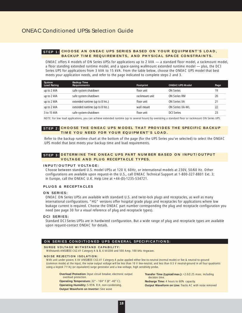
I N P U T / O U T P U T V O LT A G E :Choose between standard U.S. model UPSs at 120 V, 60Hz, or international models at 230V, 50/60 Hz. Other configurations are available upon request-in the U.S., call ONEAC Technical Support at 1-800-327-8801 Ext. 3; in Europe, call the ONEAC U.K. Help Line at +44-(0)-1235-534721.
P L U G S & R E C E P T A C L E S
O N S E R I E S :ONEAC ON Series UPSs are available with standard U.S. and twist-lock plugs and receptacles, as well as many international configurations. “HG” versions offer hospital grade plugs and receptacles for applications where low leakage current is required. Choose the ONEAC part number corresponding the plug and receptacle configuration youneed (see page 30 for a visual reference of plug and receptacle types).
D C I S E R I E S :Standard DCI Series UPSs are in hardwired configuration. But a wide range of plug and receptacle types are availableupon request-contact ONEAC for details.
18
ONEAC Conditioned UPSs Selection Guide
ONEAC offers 4 models of ON Series UPSs for applications up to 2 kVA — a standard floor model, a rackmount model,a floor standing extended runtime model, and a space-saving wallmount extended runtime model — plus, the DCISeries UPS for applications from 3 kVA to 15 kVA. From the table below, choose the ONEAC UPS model that bestmeets your application needs, and refer to the page indicated to complete steps 2 and 3.
S T E P 1 :
S T E P 2 :
System Backup TimeLoad Rating Requirements Footprint ONEAC UPS Model Page
up to 2 kVA safe system shutdown floor unit ON Series 19
up to 2 kVA safe system shutdown rackmount unit ON Series RM 20
up to 2 kVA extended runtime (up to 8 hrs.) floor unit ON Series XA 21
up to 2 kVA extended runtime (up to 8 hrs.) wall mount ON Series XA-WL 22
3 to 15 kVA safe system shutdown floor unit DCI Series 23
NOTE: For low load applications, you can achieve extended runtime (up to several hours) by oversizing a standard floor or rackmount ON Series UPS.
Refer to the backup runtime chart at the bottom of the page (for the UPS Series you’ve selected) to select the ONEACUPS model that best meets your backup time and load requirements.
D E T E R M I N E T H E O N E A C U P S P A R T N U M B E R B A S E D O N I N P U T / O U T P U TV O LT A G E A N D P L U G R E C E P T A C L E T Y P E S .
S T E P 3 :
S U R G E V O LT A G E W I T H S TA N D C A P A B I L I T Y :Withstands ANSI/IEEE C62.41 Category A & B, 6 kV/200 and 500 Amp, 100 kHz ringwave.
N O I S E R E J E C T I O N I S O L AT I O N : With unit under power, 6 kV ANSI/IEEE C62.41 Category A pulse applied either line-to-neutral (normal mode) or live & neutral-to-ground (common mode) at the input, the noise output voltage will be less than 10 V line-neutral, and less than 0.5 V neutral-ground in all four quadrants using a keytek 711AJ (or equivalent) surge generator and a low-voltage, high sensitivity probe.
O N S E R I E S C O N D I T I O N E D U P S G E N E R A L S P E C I F I C A T I O N S :
Overload Protection: Input circuit breaker, electronic output overload protection.
Operating Temperature: 32° - 104° F (0° -40° C).Operating Humidity: 5-95% R.H. non-condensing.Output Waveform on Inverter: Sine wave
Transfer Time (typical/max.): <2.0/2.25 msec. including decision time.
Recharge Time: 4 hours to 60% capacity.Output Waveform on Line: Tracks AC with noise removed

19
S E R I E S O N
Single Phase, 120 V, 60 Hz for US Models
Rating: 400 VA-2 kVA250-1300 W
S E R I E S O N
Single Phase, 230 V, 50/60 Hz for International Models
Rating: 400 VA-2 kVA250-1400 W
MODEL ON ON ON ON ON400A 600A 900A 1300A 2000A*
Output Rating (VA) 400 600 900 1300 1850
Watts (W) 250 400 600 900 1300
Frequency (Hz) 60 60 60 60 60
Input/Output Voltage (VAC) 120 120 120 120 120
Load Regulation (RMS) ± 3% ± 3% ± 3% ± 3% ± 3%
Inrush - 1/2 Cycle (Amps) 100 150 200 300 400
Surge Current (Amps) 1 sec. typical 20 30 40 60 80
Surge Current (Amps)4 sec. typical 10 15 20 30 40
1 kHz Forward Transfer Impedance (Ohms) < 5 < 4 < 3 < 2.5 < 2
Efficiency (%) 90 83 83 87 83
Approvals UL, C/UL (all models)
Line Cord (feet) 6 6 6 6 6
Height Inches (cm) 7.5” (19) 7.5” (19) 12” (31) 12” (31) 12” (31)
Width Inches (cm) 8.3” (21) 8.3” (21) 8.3” (21) 8.3” (21) 8.3” (21)
Depth Inches (cm) 15.5” (39) 18.5” (47) 18.5” (47) 21” (53) 18.5” (47)
Shipping Weight lbs. (kg.) 37 (17) 48 (22) 68 (30) 95 (43) 66 (30)
*Note: The ON2000 consists of a power unit and a separate battery unit.Dimensions for the battery unit are H = 7.5” (19cm), W = 8.3” (21cm), D = 18.5”(47cm). Shipping weight is 76lbs.(35kg).
MODEL ON ON ON ON ON400I 600I 900I 1300I 2000I*
Output Rating (VA) 400 600 900 1300 2000
Watts (W) 250 400 600 900 1400
Frequency (Hz) 50/60 50/60 50/60 50/60 50/60
Input/Output Voltage (VAC) 230 230 230 230 230
Load Regulation (RMS) ± 3% ± 3% ± 3% ± 3% ± 3%
Inrush - 1/2 Cycle (Amps) 60 80 100 200 240
Surge Current (Amps) 1 sec. typical 12 15 20 40 48
Surge Current (Amps) 4 sec. typical 6 7.5 10 20 24
1 kHz Forward Transfer Impedance Ohms < 20 < 15 < 12 < 10 < 8
Efficiency (%) 90 83 83 87 83
Approvals CE, GS (all models)
Line Cord (cm) 180 180 180 180 180
Height Inches (cm) 7.5” (19) 7.5” (19) 12” (31) 12” (31) 12” (31)
Width Inches (cm) 8.3” (21) 8.3” (21) 8.3” (21) 8.3” (21) 8.3” (21)
Depth Inches (cm) 15.5” (39) 18.5” (47) 18.5” (47) 21” (53) 18.5” (47)
Shipping Weight lbs. (kg.) 37 (17) 48 (22) 68 (30) 95 (43) 66 (30)
PART NUMBER PLUG RECEPTACLES (#)
ON400A - SN 5-15P 5-15R (4)
ON600A - SN 5-15P 5-15R (4)
ON900A - SN 5-15P 5-15R (6)
ON1300A - SN 5-15P 5-15R (8)
ON2000A - SN 5-20P 5-15R (8)
PART NUMBER PLUG RECEPTACLES (#)
ON400I - SN IEC IEC (4)
ON600I - SN IEC IEC (4)
ON900I - SN IEC IEC (4)
ON1300I - SN IEC IEC (8)
ON2000I - SN IEC IEC (8)
60 Hz, 230 V models are available upon request.
BACKUP RUNTIME(HOURS:MINUTES)VA LOAD: 100 150 200 250 300 400 500 600 700 800 900 1200 1850
MODEL WATT LOAD: 65 100 130 165 195 260 325 390 455 520 585 780 1200
ON400 :30 :17 :12 :09 :07 :04
ON600 :59 :44 :31 :23 :20 :15 :09 :08
ON900 1:20 1:10 :51 :33 :27 :20 :14 :12 :10 :07 :06
ON1300 3:22 2:10 1:35 1:14 1:00 :44 :34 :28 :23 :20 :17 :12
ON2000 5:10 3:37 2:48 2:17 1:56 1:29 1:12 1:00 :52 :45 :40 :29 :17

20
S E R I E S O N - R A C K M O U N T
Single Phase, 120 V, 60 Hz for US Models
Rating: 600 VA-2 kVA600-1300 W
S E R I E S O N - R A C K M O U N T
Single Phase, 230 V, 50/60 Hz for International Models
Rating: 600 VA-2 kVA600-1400 W
MODEL ON ON ON ON600A-RM 900A-RM 1300A-RM 2000A-RM*
Output Rating (VA) 600 900 1300 1850
Watts (W) 400 600 900 1300
Frequency (Hz) 60 60 60 60
Input/Output Voltage (VAC) 120 120 120 120
Load Regulation (RMS) ± 3% ± 3% ± 3% ± 3%
Inrush - 1/2 Cycle (Amps) 150 200 300 400
Surge Current (Amps) 1 sec. typical 30 40 60 80
Surge Current (Amps) 4 sec. typical 15 20 30 40
1 kHz Forward Transfer Impedance (Ohms) < 4 < 3 < 2.5 < 2
Efficiency (%) 83 83 87 83
Approvals UL, C/UL (all models)
Line Cord (feet) 6 6 6 6
Height Inches (cm) 6.9” (18) 6.9” (18) 10.5” (27) 10.5” (27)
Width Inches (cm) 19” (48) 19” (48) 19 (48) 19” (48)
Depth Inches (cm) 15” (38) 15” (38) 15” (38) 15” (38)
Shipping Weight lbs. (kg.) 50 (23) 69 (31) 101 (46) 72 (33)
*The ON2000 consists of a power unit and a separate battery unit. Dimensions forthe battery unit are H = 10.5” (27cm), W = 19” (48cm), D = 9” (23cm). Shippingweight is 76lbs.(35kg).
MODEL ON ON ON ON600I-RM 900I-RM 1300I-RM 2000I-RM*
Output Rating (VA) 600 900 1300 2000
Watts (W) 400 600 900 1400
Frequency (Hz) 50/60 50/60 50/60 50/60
Input/Output Voltage (VAC) 230 230 230 230
Load Regulation (RMS) ± 3% ± 3% ± 3% ± 3%
Inrush - 1/2 Cycle (Amps) 80 100 200 240
Surge Current (Amps) 1 sec. typical 15 20 40 48
Surge Current (Amps) 4 sec. typical 7.5 10 20 24
1 kHz Forward Transfer Impedance (Ohms) < 15 < 12 < 10 < 8
Efficiency (%) 83 83 87 83
Approvals CE, GS (all models)
Line Cord (cm) 180 180 180 180
Height Inches (cm) 6.9” (18) 6.9” (18) 10.5” (27) 10.5” (27)
Width Inches (cm) 19” (48) 19” (48) 19” (48) 19” (48)
Depth Inches (cm) 15” (38) 15” (38) 15” (38) 15” (38)
Shipping Weight lbs. (kg.) 50 (23) 69 (31) 101 (46) 72 (33)
PART NUMBER PLUG RECEPTACLES (#)
ON600A-RM - SN 5-15P 5-15R (6)
ON900A-RM - SN 5-15P 5-15R (6)
ON1300A-RM - SN 5-15P 5-15R (8)
ON2000A-RM - SN 5-20P 5-15R (8)
PART NUMBER PLUG RECEPTACLES (#)
ON600I-RM - SN IEC IEC (4)
ON900I-RM - SN IEC IEC (4)
ON1300I-RM - SN IEC IEC (8)
ON2000I-RM - SN IEC IEC (8)
All specifications subject to change without notice.
BACKUP RUNTIME(HOURS:MINUTES)VA LOAD 100 150 200 250 300 400 500 600 700 800 900 1200 1850
MODEL WATT LOAD: 65 100 130 165 195 260 325 390 455 520 585 780 1200
ON600 :59 :44 :31 :23 :20 :15 :09 :08
ON900 1:20 1:10 :51 :33 :27 :20 :14 :12 :10 :07 :06
ON1300 3:22 2:10 1:35 1:14 1:00 :44 :34 :28 :23 :20 :17 :12
ON2000 5:10 3:37 2:48 2:17 1:56 1:29 1:12 1:00 :52 :45 :40 :29 :17

21
S E R I E S O N - E X T E N D E D R U N T I M E U N I T S
Single Phase, 120 V, 60 Hz for US Models
Rating: 600, 900, and 1850 VA400, 600, and1300 W
S E R I E S O N - E X T E N D E D R U N T I M E U N I T S
Single Phase, 230 V, 50/60 Hz for International Models
Rating: 600, 900, and 2000 VA400, 600, 1400 W
MODEL ON ON ON BATTERY600A 900A 2000A CABINET
Output Rating (VA) 600 900 1850 n/a
Output Rating (W) 400 600 1300 n/a
Frequency (Hz) 60 60 60 n/a
Input/Output (Volts) 120 120 120 n/a
Load Regulation (RMS) ± 3% ± 3% ± 3% n/a
Inrush - 1/2 cycle (Amps) 150 200 400 n/a
Surge Current (Amps)1 sec. typical 30 40 80 n/a
Surge Current (Amps)4 sec. typical 15 20 40 n/a
1 KHZ Forward TransferImpedance (Ohms) < 4 < 3 < 2 n/a
Efficiency % 83 83 83 n/a
Approvals UL, C/UL (all models)
Line Cord Feet 6 6 6 6
Height Inches(cm) 7.5”(19) 12” (30) 12” (30) 7.5” (27)
Width Inches (cm) 8.3” (22) 8.3” (22) 8.3” (22) 8.3” (22)
Depth Inches (cm) 18.5” (47) 18.5” (47) 21” (53) 9” (23)
Shipping Weight lbs (kg.) 48 (22) 68 (31) 66 (30) 74 (34)
MODEL ON ON ON BATTERY600I 900I 2000I CABINET
Output Rating (VA) 600 900 2000 n/a
Output Rating (W) 400 600 1400 n/a
Frequency (Hz) 50/60 50/60 50/60 n/a
Input/Output (Volts) 230 230 230 n/a
Load Regulation (RMS) ± 3% ± 3% ± 3% n/a
Inrush - 1/2 cycle (Amps) 80 100 240 n/a
Surge Current (Amps)1 sec. typical 15 20 48 n/a
Surge Current (Amps)4 sec. typical 7.5 10 24 n/a
1 KHZ Forward TransferImpedance (Ohms) < 15 < 12 < 8 n/a
Efficiency % 83 83 83 n/a
Approvals CE, GS (all models)
Line Cord (cm) 180 180 180 180
Height Inches (cm) 7.5” (19) 12” (30) 12” (30) 7.5” (27)
Width Inches (cm) 8.3” (22) 8.3” (22) 8.3” (22) 8.3” (22)
Depth Inches (cm) 18.5” (47) 18.5” (47) 21” (53) 9” (23)
Shipping Weight lbs (kg.) 48 (22) 68 (31) 66 (30) 74 (34)
PART NUMBER PLUG RECEPTACLES (#)
ON600-XASN 5-15P 5-15R (4)
ON900-XASN 5-15P 5-15R (6)
ON2000-XASN 5-20P 5-15R (8)
ONXBC - 417 n/a n/a(Floor Mount Battery Cabinet)
All specifications subject to change without notice.
PART NUMBER PLUG RECEPTACLES (#)
ON600XI - SN IEC IEC (4)
ON900XI - SN IEC IEC (4)
ON2000XI - SN IEC IEC (8)
ONXBC - 417 n/a n/a(Floor Mount Battery Cabinet)
Note: adding a “K” to the end of a part number identifies a power unit and onebattery pack. Additional battery packs can be ordered separately under part no.ONXBC-217.
BACKUP RUNTIME(HOURS:MINUTES)POWER HEAD REQUIRED VA LOAD NUMBER OF BATTERY PACKS: 1 2 4 6 8
ON600 100 5:54 11:12
ON600 200 3:29 7:02 15:32
ON900 ON600 400 1:40 3:43 8:14 12:41 19:46
ON2000 ON900 ON600 600 1:04 2:34 5:36 8:28 12:00
ON2000 ON900 800 0:48 2:02 4:23 6:25 9:13
ON2000 1000 0:38 1:42 3:38 5:07 7:28
ON2000 1500 0:22 1:00 2:16 2:56 4:28
ON2000 1850 0:16 0:41 1:39 2:09 3:20

22
S E R I E S O N - W A L L M O U N TE X T E N D E D R U N T I M E U N I T S
Single Phase, 120 V, 60 Hz for US Models
Rating: 400 and 600 VA250 and 400 W
S E R I E S O N - W A L L M O U N TE X T E N D E D R U N T I M E U N I T S
Single Phase, 230 V, 50/60 Hz for International Models
Rating: 400 and 600 VA250 and 400 W
MODEL ON400A ON600A BATTERY CABINET
Output Rating (VA) 400 600 n/a
Output Rating (W) 250 400 n/a
Frequency (Hz) 60 60 n/a
Input/Output (Volts) 120 120 n/a
Load Regulation (RMS) ± 3% ± 3% n/a
Inrush - 1/2 cycle (Amps) 100 150 n/a
Surge Current (Amps)1 sec. typical 20 30 n/a
Surge Current (Amps)4 sec. typical 10 15 n/a
1 KHZ Forward TransferImpedance (Ohms) < 5 < 4 n/a
Efficiency % 90 83 n/a
Approvals UL, C/UL (all models)
Line Cord Feet 6 6 6
Height Feet (cm) 15”(38) 15” (38) 7.5” (27)
Width Feet (cm) 8.3” (22) 8.3” (22) 8.3” (22)
Depth Feet (cm) 9” (23) 9” (23) 9” (23)
Shipping Weight lbs (kg.) 29 (13) 33 (15) 39 (18)
MODEL ON400I ON600I BATTERY CABINET
Output Rating (VA) 400 600 n/a
Output Rating (W) 250 400 n/a
Frequency (Hz) 50/60 50/60 n/a
Input/Output (Volts) 230 230 n/a
Load Regulation (RMS) ± 3% ± 3% n/a
Inrush - 1/2 cycle (Amps) 60 80 n/a
Surge Current (Amps)1 sec. typical 12 15 n/a
Surge Current (Amps)4 sec. typical 6 7.5 n/a
1 KHZ Forward TransferImpedance (Ohms) < 20 < 15 n/a
Efficiency % 90 83 n/a
Approvals CE, GS (all models)
Line Cord (cm) 180 180 180
Height Feet (cm) 15” (38) 15” (38) 7.5” (27)
Width Feet (cm) 8.3” (22) 8.3” (22) 8.3” (22)
Depth Feet (cm) 9” (23) 9” (23) 9” (23)
Shipping Weight lbs (kg.) 29 (13) 33 (15) 39 (18)
PART NUMBER PLUG RECEPTACLES (#)
ON400XA - WL-SN 5-15P 5-15R (4)
ON600XA - WL-SN 5-15P 5-15R (4)
ONXBC - WL - 217 (Battery Cabinet) n/a n/a
Note: adding a “K” to the end of a part number identifies a power unit and onebattery pack. Additional battery packs can be ordered separately under part no.ONXBC-WL-217. All specifications subject to change without notice.
PART NUMBER PLUG RECEPTACLES (#)
ON400XI - WL-SN IEC IEC (4)
ON600XI - WL-SN IEC IEC (4)
ONXBC - WL - 217 (Battery Cabinet) n/a n/a
BACKUP RUNTIME(HOURS:MINUTES)POWER HEAD REQUIRED VA LOAD NUMBER OF BATTERY PACKS: 1 2 4 6 8
ON400 100 3:03 6:30 15:00
ON600 ON400 200 1:36 2:42 6:00 17:00
ON600 ON400 400 0:48 1:28 3:06 5:30 8:30
ON600 600 0:35 0:51 1:46 3:10 6:10

23
kVA/kW Rating 3 5 7.5 10 15
Input Voltage (VAC) 120 208* 240 120 208* 240 208* 240 208* 240 480 208* 240 480
Input Voltage Range +15%, -20% of nominal without transferring to battery
Input Frequency Range (Hz) 47 to 63 Hz without transferring to battery
Phase 1 1 1 1 1 1 1 1 1/3 1/3 1/3 1/3 1/3 1/3
Max. Input Current (Vac) 48 30 30 79 48 48 74 74 30/59 113/52 56/26 180/80 157/70 78/35
Output Voltage (Vac) 120 208* 240 120 208* 240 120 208* 240 120 208* 240 120 208* 240
Phase 1 1 1 1 1 1 1 1 1 1 1 1 1 1 1
Frequency (Hz)† 60 60 60 60 60 60 60 60 60 60 60 60 60 60 60
Max. Output Current (Aac) 25 14.5 12.5 42 24 21 62.5 36 31 83.8 48 42 12.5 72 62.5
Efficiency Half/Full Load (Single-Phase Output) 78%/79% 83%/83% 83%/83% 81%/85% 81%/85%
Efficiency Half/Full Load (Three-Phase Input) - - - 86%/86% 86%87%
Surge Voltage Withstand Capability ANSI/IEEE C62.41 Category A & B ringwave, 6kV/200 & 500A, 100Khz and Category B impulse, 6kV/3kA.
Surge Voltage Let-Through(Max.) when subjected to Less than 10V Normal Mode (L-N), less than 0.5 V Common6kV ANSI/IEEE C62.41 Cat. A Test Mode (N-G) in both normal and bypass conditions.
Load Power Factor Any
Load Crest Factor Range Up to 5:1 crest factor without derating
Standard Input Conn. Hardwired** Hardwired** Hardwired** Hardwired** Hardwired**
Standard Output Conn. Hardwired** Hardwired** Hardwired** Hardwired** Hardwired**
Heat Rejection (BTU/hr.)(Single-Phase Input) 2100 3500 5250 6020 9038
Heat Rejection (BTU/hr.)(Three-Phase Input) - - - 5560 7650
Typical Battery Runtime (full load/half load)*** 7/22 mins 7/22 mins 10/30 mins 22/64 mins 14/42 mins
Typical Battery Recharge Time to 100% Capacity 45 mins. 45 mins. 60 mins. 90 mins. 75 mins.
Limited Warranty 1 year parts, 90 days on-site labor
Approvals UL Listed, FCC Class A compliance
Weight (lbs.) 310 425 620 1200 1200
Height (Inches) 27 27 36 53 53
Width (Inches) 13 13 16 18 18
Depth (Inches) 31 31 31 38.5 38.5
* Standard Voltages** Optional plug and receptacle versions available-contact factory for details*** Optional Extended Run-Time Battery Packs available-up to 8 hours† 50 Hz models available-contact factory for detailsAll specifications are subject to change without notice.
MODEL DCI3000 DCI5000 DCI7500 DCI10000 DCI5000
S E R I E S D C I
Single and Three Phase, 60 HzRating: 3-15 kVA/kW

S E L E C T T H E O N E A C A C C E S S O R Y K I T F R O M T H E T A B L E O N T H E F A C I N GP A G E ( P A G E 2 5 ) , B A S E D O N Y O U R O P E R A T I N G S Y S T E M , A N D T H E L E V E LO F M A N A G E M E N T C A P A B I L I T Y R E Q U I R E D .
S E L E C T T H E O N E A C A C C E S S O R Y K I T P R E F I X , B A S E D O N Y O U R R E Q U I R E M E N T S ( D O E S N O T A P P LY T O “ O T H E R ” O P E R A T I N G S Y S T E M S )
24
ONEAC UPS Communication Kits
ONEAC UPS Communication Kits, with an ON Series UPS, provide a comprehensive range of powerful performance features for attaining total power fault tolerance and complete manageability. Features include unattended shutdownwhen a prolonged power outage strikes, intelligent communications for remote control, UPS and AC line event monitoring and logging and customized programmable performance options.
ONEAC UPS communications kits are available for Novell NetWare (3 options to choose from), OS/2, Windows NT,Banyan, all major versions of UNIX, plus SNMP network management systems such as HP OpenView, Novell NMS, SunNet Manager and others. Refer to the chart below to determine the ONEAC part number and features available for your operating system.
KIT TYPE INCLUDES PREFIX
Accessory Kit Interface Card, Software and Cable AK-
Software Kit Software and Cable SK-
Cable Kit Cable CK-
Example: To order an ONEAC Accessory Kit for NetWare with remote management capability that includes interface card, software, cable and manual, the ONEAC part number is AK-NOVMOP\RM.
S T E P 2 :
S T E P 1 :
NOVELL NETWARE (3 OPTIONS) OS/2 WINDOWS NTBASIC ADVANCED REMOTE MGMT. UNIX LAN SERVER BANYAN SNMP
Automated Power Fail ResponseAutomatic system shutdown
Automatic system reboot
Multiple server shutdown/reboot
Administrator/user alerts
Customizable shutdown script (NT)UPS battery conservation mode (NT)
UPS & AC Line Status InformationReport results of UPS self-tests
Service/maintenance alerts
Battery replacement warning
UPS status information
UPS & power event logging *
Remote ManagementRemote control via workstation
Real-time paging alerts
Real-time e-mail alerts
SNMP
*depends on manager

25
ONEAC SOFTWARE/ OPERATING SYSTEM ONEAC ACCESSORY KIT SERIES
NetWare 3.x, 4.1ONEAC offers a number of management support options for NetWare — three cable/board interface kits for supporting the UPS.NLM providedwith NetWare, and three ONEAC software interface kits to support basic, advanced or remote management features.
Software Interface Kits (Add features and functionality beyond that provided in NetWare):
MopUPS (Basic — Unattended Shutdown) (AK- OR SK-)NOVMOPMopUPS Basic UPS monitoring software monitors Power Fail, Power Return, and Low Battery conditions. Upon receiving alerts, the program sends messages to the system console and to all users logged onto the server. Broadcast message text can be customized.
MopUPSPlus (Advanced — Adds Testing and UPS Status Monitoring) (AK- OR SK-)NOVMOP+Includes all the features provided by MopUPS, plus the capability to log broadcast alert conditions in the System Error Log file, remote pager capability, and a graphical/GUI-based monitoring utility.
MopUPS/RM (Adds Advanced Remote Management Capabilities) (AK- OR SK-)NOVMOP/RMAdvanced monitoring software provides all features of MopUPSPlus, plus the ability to review system error messages via the “View Log File”from the Available Topics menu, multiple server support to execute unattended shutdown of two servers sharing a single UPS, and local access to remote servers or workstations running MopUPS/RM.
Cable/Board Interface Kits (Allow you to use the UPS.NLM provided with NetWare):
Using a PS/2 compatible mouseport CK-NOV/PS2M
Using a UPS monitoring board, or disk co-processor board (DCB) that supports UPS monitoring CK-NOV/DCB
If you do not have a DCB UPS board and wish to leave the serial port open IK-UPSMON
UNIXONEAC UNIX software monitors UPS status, and initiates an automated and orderly shutdown in the event of a prolonged outage. Additional features include UPS event logging, user alerts, and e-mail messaging when attention is required.
AIX — IBM (AK- OR SK-)AIXMOP DG/UX — Data General (AK- OR SK-)DGMOP
Digital UNIX - DEC (AK- or SK- )DECMOP HP-UX for PA-RISC — Hewlett Packard (AK- OR SK-)HPUXMOP
IRIX — Silicon Graphics (AK- OR SK-)SGIMOP MP-RAS —NCR (AK- OR SK-)MPRAS
SCO UNIX — Intel (AK- OR SK-)SCOMOP Solaris 2.x, SPARC — Sun Microsystems (AK- OR SK-)SOLMOP
Sv/88k — Motorola (AK- OR SK-)MOTMOP (4mm) SunOS 4.13 Solaris 1.x SPARC — Sun Microsystems (AK- OR SK-)SUNMOP
UnixWare (AK- OR SK-)UWAREMOP
OS/2 (AK- OR SK-)OS2MOPMopUPS Basic UPS monitoring software monitors Power Fail, Power Return, and Low Battery conditions. Upon receiving alerts, the programsends messages to the system console and to all users logged onto the server. Broadcast message text can be customized to log broadcastalert conditions in the System Error Log file, remote pager capability, and a graphical/GUI-based monitoring utility.
Other Operating SystemsOffers basic cable shutdown using built-in OS functionality.
WindowsNT CK-WINNT
Banyan VINES CK-BANYAN
AS/400 CK-AS/400
SNMPProvides all the capabilities inherent in the proposed standard UPS MIB including-Traps/Alarms to alert the network to UPS status condition requiring attention; Remote Control to program the UPS to shutdown after a preset interval, restart or reboot attached devices; Remote Testing to determine UPS status from anywhere across the WAN; and Retrievable Information to access UPS status information.
HP OpenView, Novell NMS, SunNet Manager and other SNMP network management systems AK-SNMP-NE

26
BASE TYPE SERIES APPLICATION MODEL/PART# COLOR/DESCRIPTION
66 Block M1-50 (page 27) 6 Series Standard Service-Truck Lines 6-AP BlackAnalog OPX Stations with Ring Signal
T-1 (DS-1) Digital Carrier, Digital Data 6-DC Blue
ISDN, Digital OPX Stations without Ring Signal 6-DP Yellow
Ground (earthing) Bar 350-032 n/a
5-Pin Base (page 27) 5 Series Standard Service-Truck Lines, 5S-AP BlackAnalog OPX Stations with Ring Signal
ISDN, Digital OPX Stations without Ring Signal 5S-DP Yellow
Modular Jacks (page 28) J Series Standard Service-Trunk Lines RJ-AP11 6 position, 2 wire, 1 lineAnalog OPX Stations with Ring Signal RJ-AP14 6 position, 4 wire, 2 line
RJ-AP45 8 position, 8 wire, 4 line
ISDN, Digital OPX without Ring Signal RJ-DP11 6 position, 2 wire, 1 lineRJ-DP14 6 position, 4 wire, 2 lineRJ-DP45 8 position, 8 wire, 4 line
Standard service Analog-Fax, Modem & Data Terminal LJ-AP-420 6 position, 4 wire, 2 line
Krone LSA Plus 237A 10 Series Standard service CO line (for either analog or digital exchange)or Compatible (page 29) Analog external extensions (key station or standard system telephone) 10-AP-200 White
ISDN-Digital external extensions (key station or standard system phone) 10-DP Yellow
10-1 Series Standard service CO line (for either analog or digital exchange)Analog external extensions (key station or standard system telephone) 10AP-1 BlackISDN-Digital external extensions (key station or standard system phone) 10DP-1 Yellow
One ground (earthing) bar is required for each termination strip 350-139 n/a
ONEAC offers two types of communication line protectors for the Krone LSA Plus 237A or compatible. Choose the 10 Series product if you use all 10 positions for the same type of service. The 10-1 Series fits on the same 10-position block, but provides an individual protector for each telecom line. Choose it to allow the flexibility to accom-modate different service types on the same block, or if fewer than 10 positions are in use.
O N E A C B R E A K S “ T H E R I N G V O LT A G E B A R R I E R ”
Conventional protectors (either gas tube or solid-state) are designed to clamp above the operating DC bias and the ring voltage level. The OnLine’s ability to differentiate signals based on frequency permits the useful signals to pass while preventing transients from damaging semiconductor based electronics.
Communications Line Protector Selection Guide
C H O O S E T H E O N E A C O N L I N E P R O D U C T S E R I E ST H A T M A T C H E S T H E B A S E / B L O C K U S E D B Y Y O U R C O M M U N I C A T I O N S I N T E R F A C E .
S E L E C T T H E O N E A C P A R T N U M B E R A P P R O P R I A T E T O T H E T Y P E O F S E R V I C E U S E D .
S T E P 2 :
S T E P 1 :

27
5-PIN BASE 66 BLOCK M1-50DESCRIPTION MODEL 5S-AP 5S-DP 6-AP 6-DC 6-DP
Transient Voltage Performancewith 1/1µs, 200 V Peak: 28 V 28 V 28 V 28 V 28 V
Impulse Voltage Performancewith 10/1000 µs, 1500 V, 100 A: 100 V 50 V 100 V 100 V 50 V
DC Breakdown Voltage @ 2000 V/sec. 280 V 70 V 280 V 280 V 70 V
Rated Impulse Discharge with 10/1000 µs: 100A 100A 100A 100A 100A
Response Time: < 1 Nanosecond (all models)
DC Holdover @ 25° C, 20 ms max. 200mA 200mA 200mA 200mA 200mA
On State Voltage with 1 Amp RMS: < 5V < 5V < 5V < 5V < 5V
Capacitance @ 50 VDC, 5VAC, 1KHZ: <200 pf <200 pf <200 pf <200 pf <200 pf
Insulation Resistance: >100 MΩ >100 MΩ >100 MΩ >100 MΩ >100 MΩ
Fused (fails open) n/a n/a yes yes yes
Service Life with 10/1000µs@ +/- 10 Amps: Unlimited Unlimited Unlimited Unlimited Unlimited@ +/- 100 Amps: Unlimited Unlimited Unlimited Unlimited Unlimited@ +/- 300 Amps: Fail-Safe Fail-Safe Fail-Safe Fail-Safe Fail-Safe
Resettable Overcurrent Protection (Sneak Current) @ 25° C, 300 mA 300 mA 300 mA 300 mA 300 mA
UL Listings 497 497 497, 497A 497, 497A 497, 497 A
Storage Temperature -40°C to 85°C -40°C to 85°C -40°C to 85°C -40°C to 85°C -40°C to 85°C
Operating Temperature -40°C to 65°C -40°C to 65°C -40°C to 65°C -40°C to 65°C -40°C to 65°C
Color Code Black Yellow Black Blue Yellow
Test Points Yes Yes Yes Yes Yes
O n L i n e — f o r 5 P i n P r o t e c t o r B a s e s & 6 6 B l o c k s
28
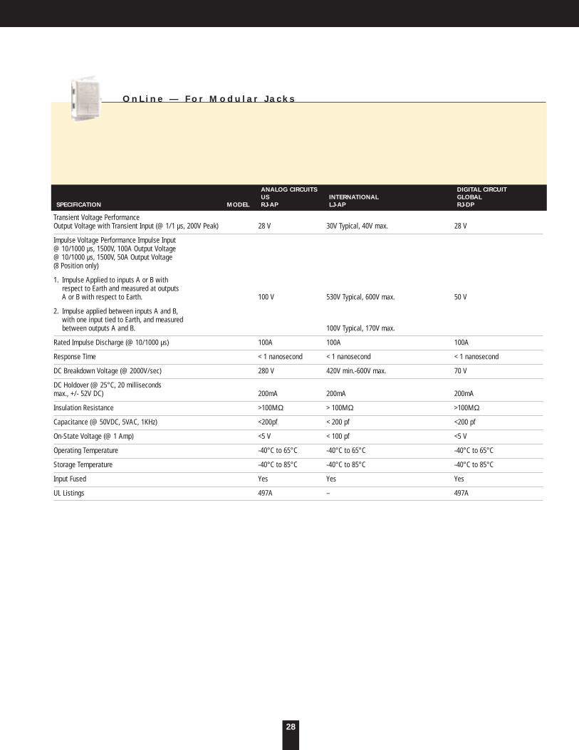
ANALOG CIRCUITS DIGITAL CIRCUITUS INTERNATIONAL GLOBAL
SPECIFICATION MODEL RJ-AP LJ-AP RJ-DP
Transient Voltage PerformanceOutput Voltage with Transient Input (@ 1/1 µs, 200V Peak) 28 V 30V Typical, 40V max. 28 V
Impulse Voltage Performance Impulse Input@ 10/1000 µs, 1500V, 100A Output Voltage@ 10/1000 µs, 1500V, 50A Output Voltage(8 Position only)
1. Impulse Applied to inputs A or B with respect to Earth and measured at outputs A or B with respect to Earth. 100 V 530V Typical, 600V max. 50 V
2. Impulse applied between inputs A and B,with one input tied to Earth, and measuredbetween outputs A and B. 100V Typical, 170V max.
Rated Impulse Discharge (@ 10/1000 µs) 100A 100A 100A
Response Time < 1 nanosecond < 1 nanosecond < 1 nanosecond
DC Breakdown Voltage (@ 2000V/sec) 280 V 420V min.-600V max. 70 V
DC Holdover (@ 25°C, 20 milliseconds max., +/- 52V DC) 200mA 200mA 200mA
Insulation Resistance >100MΩ > 100MΩ >100MΩ
Capacitance (@ 50VDC, 5VAC, 1KHz) <200pf < 200 pf <200 pf
On-State Voltage (@ 1 Amp) <5 V < 100 pf <5 V
Operating Temperature -40°C to 65°C -40°C to 65°C -40°C to 65°C
Storage Temperature -40°C to 85°C -40°C to 85°C -40°C to 85°C
Input Fused Yes Yes Yes
UL Listings 497A – 497A
O n L i n e — F o r M o d u l a r J a c k s
29
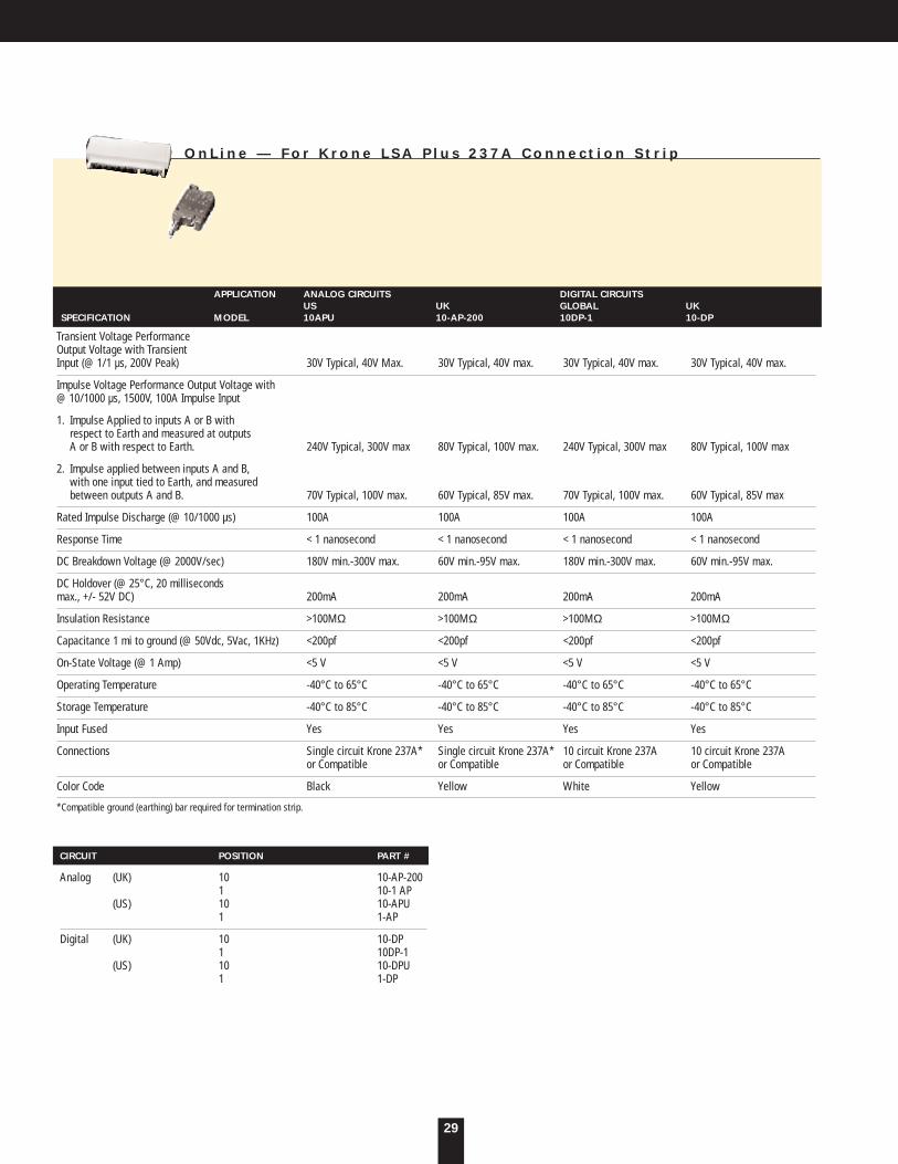
APPLICATION ANALOG CIRCUITS DIGITAL CIRCUITSUS UK GLOBAL UK
SPECIFICATION MODEL 10APU 10-AP-200 10DP-1 10-DP
Transient Voltage PerformanceOutput Voltage with Transient Input (@ 1/1 µs, 200V Peak) 30V Typical, 40V Max. 30V Typical, 40V max. 30V Typical, 40V max. 30V Typical, 40V max.
Impulse Voltage Performance Output Voltage with@ 10/1000 µs, 1500V, 100A Impulse Input
1. Impulse Applied to inputs A or B with respect to Earth and measured at outputs A or B with respect to Earth. 240V Typical, 300V max 80V Typical, 100V max. 240V Typical, 300V max 80V Typical, 100V max
2. Impulse applied between inputs A and B,with one input tied to Earth, and measuredbetween outputs A and B. 70V Typical, 100V max. 60V Typical, 85V max. 70V Typical, 100V max. 60V Typical, 85V max
Rated Impulse Discharge (@ 10/1000 µs) 100A 100A 100A 100A
Response Time < 1 nanosecond < 1 nanosecond < 1 nanosecond < 1 nanosecond
DC Breakdown Voltage (@ 2000V/sec) 180V min.-300V max. 60V min.-95V max. 180V min.-300V max. 60V min.-95V max.
DC Holdover (@ 25°C, 20 milliseconds max., +/- 52V DC) 200mA 200mA 200mA 200mA
Insulation Resistance >100MΩ >100MΩ >100MΩ >100MΩ
Capacitance 1 mi to ground (@ 50Vdc, 5Vac, 1KHz) <200pf <200pf <200pf <200pf
On-State Voltage (@ 1 Amp) <5 V <5 V <5 V <5 V
Operating Temperature -40°C to 65°C -40°C to 65°C -40°C to 65°C -40°C to 65°C
Storage Temperature -40°C to 85°C -40°C to 85°C -40°C to 85°C -40°C to 85°C
Input Fused Yes Yes Yes Yes
Connections Single circuit Krone 237A* Single circuit Krone 237A* 10 circuit Krone 237A 10 circuit Krone 237Aor Compatible or Compatible or Compatible or Compatible
Color Code Black Yellow White Yellow
*Compatible ground (earthing) bar required for termination strip.
O n L i n e — F o r K r o n e L S A P l u s 2 3 7 A C o n n e c t i o n S t r i p
CIRCUIT POSITION PART #
Analog (UK) 10 10-AP-2001 10-1 AP
(US) 10 10-APU1 1-AP
Digital (UK) 10 10-DP1 10DP-1
(US) 10 10-DPU1 1-DP

30
Key to connectors:
L 2 1 - 3 0 R
5 - 1 5 P
5 - 2 0 P
L 5 - 1 5 P5 - 1 5 R
5 - 2 0 R
L 5 - 1 5 R
L 5 - 2 0 P
6 - 1 5 P
L 5 - 3 0 P
L 6 - 2 0 P
L 6 - 3 0 P
L 5 - 2 0 R
L 5 - 3 0 R
6 - 1 5 R
CSA5-20R
L 6 - 2 0 R
L 6 - 3 0 R
L 1 4 - 2 0 R
L 1 4 - 3 0 R
L 1 4 - 2 0 P
L 1 4 - 3 0 P
6 - 2 0 P
5 - 5 0 P 5 - 5 0 R
L 2 1 - 3 0 P
6 - 2 0 R
1 4 - 6 0 P
1 5 - 6 0 P
1 4 - 6 0 R
1 5 - 6 0 R
L 2 1 - 2 0 RL 2 1 - 2 0 P
I E C
U . K .
F R E N C H
A U S T R A L I A N
I T A L I A N
S W I S S
G E R M A N“ S c h u k o ”
I N T E R N A T I O N A LU . S . S T A N D A R DP L U G R E C E P T A C L E
U . S . T W I S T L O C KP L U G R E C E P T A C L E

31
WarrantyU N I T S
ONEAC products are warranted free from defects in materials and workmanship for five years. This warranty is limited to repairing orreplacing, at ONEAC’s option, any defective component, circuit board, or module contained within the product only when it isreturned with an ONEAC Return Material Authorization (RMA) number to ONEAC or to an ONEAC-designated repair facility. In allcases, the customer is responsible for shipping charges to and from ONEAC or the ONEAC-designated repair facility.
B A T T E R I E SCertain modules or peripherals included with the product but not manufactured by ONEAC, including but not limited to batteries orbattery packs, are warranted for two years or the extent of the manufacturer’s warranty, whichever is longer.
L I M I T A T I O N S O F W A R R A N T YThis limited warranty does not cover any losses or damage resulting from shipment to or from the customer, or from improper installation, inappropriate environment, abuse, modifications, adjustments, or unauthorized repair.
E X C L U S I V E R E M E D I E SExcept as set forth herein and except as to title, there are no warranties, express or implied, or any affirmations of fact or promises byONEAC for the products, their merchantability, or fitness for any particular purpose. In no event shall ONEAC be liable for lost profits,goodwill, or any other special or consequential damages.
R E T U R N P R O C E D U R ETo return a unit, contact ONEAC for a Return Material Authorization (RMA) number. This number must be marked on the shippingcarton and packing slip of the unit returned. The customer is responsible for repair charges for damages incurred in shipment thatresult from inadequate packing of the product.
Technical Support
S T A N D A R D S E R V I C E S I N C L U D E :
• Telephone support during normal business hours.
• After hours telephone support beeper service.
• Assistance with orders for replacement batteries and units.
• In-house repair of all ONEAC products.
• Technical assistance and applications advice.
A D D I T I O N A L S E R V I C E O P T I O N S I N C L U D E :
• On-site service by a trained ONEAC Service Technician.
• Customer training seminars for help desk personnel, depot repair technicians, and others. Subjects include an overview of product functions and operation, installation and maintenance, basic telephone support, and more.
• On-site assistance with product installations.
• Warranty matching — ONEAC will match any competitor’s warranty package.
• Hot Spares Program — Products of a customer’s choice will be kept at an Airline Air Freight Company for immediate overnight shipment to any customer location.
• ON Series UPS Battery Program — Custom battery protection replacement can be made available to meet individual customer needs.
• Enhancement Program for UPS and instrumentation products — These products can be returned to ONEAC for latest product upgrades.
• Warranty replacement for UPS products — Reconditioned UPS products are also available for purchase.
H O W T O C O N T A C T O N E A C T E C H N I C A L S U P P O R T :
TELEPHONE NUMBER 800-327-8801, Extension 3
NORMAL HOURS 7 a.m. - 5 p.m. Central Time, Monday through Friday, except company holidays
BEEPER HOURS 5 p.m. - 7 a.m.
After the hours of 5pm CST, all calls are forwarded to a beeper. An ONEAC Technical Support Representative will returnyour call within one half hour, except during the hours of 10 p.m. - 7 a.m. Response during 10 p.m. - 7 a.m. is on an emergency basis only.
ONEAC dedicates itself to supporting customers long after the sale takes place by providing a broad range of product services.

ONEAC EUROPE18 & 20 Blacklands WayAbingdon Business ParkAbingdon, Oxfordshire OX14 1DYUNITED KINGDOM
Tel +44-(0)-1235-534721Fax +44-(0)-1235-534197
ONEAC: A higher level of confidence
An ISO 9001 company, ONEAC has manufacturing plants in Libertyville, Illinois and Abingdon, England.
ONEAC USA27944 North Bradley RoadLibertyville, Illinois 60048-9700USA
Tel 847-816-6000Toll Free 800-327-8801Fax 847-680-5124
A H I G H E R L E V E L O F C O N F I D E N C E
Form No.935-012 Rev. E Printed in USA Copyright 1997 ONEAC Corporation
We live in an information age.
One made possible by semiconductor technology. The irony is, as that technology increases in
sophistication, so does its susceptibility to power disturbances. To the point where traditional pro-
tection devices that had been adequate in the past are now falling short. That’s not true of ONEAC.
ONEAC products meet today’s needs.
Created by a design group that leads the industry in developing products capable of taming even
the most hostile environments, ONEAC, in installation after installation, has proven its ability to
provide the advanced protection modern electronic systems require. And we maintain a leading
position in customer service, as well. With flexible, quality-driven manufacturing facilities organized
to ship within 24 hours, even when product variations to meet specific applications are required.