one goss model m-600 c web offset printing press with 4...
TRANSCRIPT

ONE GOSS MODEL M-600 C
WEB OFFSET PRINTING PRESS
WITH 4 UNITS 1 WEB WITH ONE JF-55 FOLDER
MASTER PRESS
Cut-off length 625 mm
Maximum transfer area 618 x 960 mm
Maximum web width 965 mm
Maximum printing speed up
to
55 000 IPH*
Maximum web speed 9.55 m/s
Power supply 400 Volts ± 10%
3 Phases + Earth
50 Hertz
All the equipment connected to the main control must be designed for the
above power supply
Ancillary equipment in current contract and not manufactured by the SELLER
is in accordance with specifications in force at the time of contract signature
* Note : Maximal speeds are given for coated paper type LWC, MWC or
equivalent ; speeds vary according to production characteristics (paper weight,
fold type, ink coverage) and are specified in the charts or sketches of elements
of the press (dryer, folder, sheeter, …)
Actual production speed depends on elements unrelated with the inherent
performances of the press (adequate environment, correct maintenance, crew
skills, selection of consumables)
See clause 9 (h) of General Sales Conditions ONE (1) GOSS CONTIWEB horizontal splicer SH40-LI-1020 for two webs (9.7 m/s)
The SH40-LI is a horizontal, zero speed splicer using mechanical
shafts.
The integrated infeed has a web guide.
Standard equipment and features :
Integrated electronically controlled infeed for constant web tension
and infeed web up system including web guide. Remote infeed
functions and web guide controlled through press control system

Automatic program for reel loading and unloading the expired reel
(core) after the splice
Central operating panel with paper and production data read-out
on CRT display without storage
Motorized reel side lay adjustment with indication on CRT display
of splicer
Automatic splicing at any reel diameter
Festoon rollers with concave profile
One web severer
Three mechanical expanding reel shafts and one reel shaft
trolley
Remote diagnosis system through modem connection, customer
to provide dedicated telephone line
Technical data Metric
Max. splicing speed 9.7 [m/s]
Max. web width 1020 [mm]
Max. reel diameter 1270 [mm]
Max. reel weight 1600 [Kg]
Web tension infeed 150-1200 [N]
Web tension variation 1% from pre-set value
+ 5 [N]
Standard core diameter 76 [mm]
FOUR (4) GOSS Blanket to blanket printing units
Extremely rigid construction with box type frame on the gear side and
large dimensioned spacers
In-line stacked cylinder arrangement. Cylinders are all mounted on
special bearings providing maximum vibration absorption
The units are driven by individual motors (one AC drive per unit)
The plate cylinder can be automatically rotated to a fixed position to
facilitate plate-up
Chrome plated plate cylinders fitted with 40 mm wide hardened steel
bearers. Plate cylinder undercut is 0.27 mm for a 0.30 mm aluminium
plate and is equipped with a pneumatic plate lock-up device
Plate cylinder positioning is controlled from the Omnicon console,
allowing rapid plate change
The four register adjustments consist of motorized lateral ( 2 mm),
motorized circumferential ( 3 mm), motorized plate cocking ( 0.3 mm).
Unit phasing register is obtained by unit drive synchronisation
Each printing unit can be individually silenced
Platforms between the units allowing plates to be mounted or removed
easily, the web staying in the machine
Inking :
Large ink fountain with remote control of ink keys

The inking system can be converted from a 100-0-0 to a 80-10-10 split
by means of a mechanical changeover of one roller
Each inker can be silenced independently with or without the operation
of the dampener system. The upper and lower print couples can be
declutched independently of each other
Inking is ensured by a total of 15 large diameter rollers
Each inker includes :
one ceramic ink fountain roller
one nylon covered pick-up roller
one nylon roller
three nylon covered oscillating vibrators
five rubber covered distributor rollers
three rubber covered form rollers (two are self-oscillating)
one rubber covered rider roller
The vibrators are cooled by means of water circulation
All form rollers follow plate cylinder skewing (form roll following)
Two GOSS pneumatic ink scraping blades are provided per unit
Dampening
Convertible dampening system with sliding contact roller with pneumatic
switching between the two modes of dampening (film or emulsification)
from the main Omnicon console
Each dampener includes :
One rubber covered pan roller
One chrome plated metering roller with special surface treatment and
cocking adjustment
One self-oscillating rubber dampener form roller
One chrome plated jockey roller
Each unit includes an integrated filtering assembly in the dampening
water circuit
The GOSS dampening system is designed for a high quality printing on
coated or semi coated paper
Other equipment
A motor driven oil pump provides pressurized circulation as well as
cascade lubrication of gears, unit clutches, oscillating mechanism, and
all cylinder bearings. Oil cooling is provided through a heat exchanger
and oil flow and temperature are monitored, indicated, and the press is
stopped in the event of an oil flow failure

A motorized bypass web lead for systems with more than one web is
provided. The web-up rolls under the units included are as follows :
5 units : bypass under the first unit after the infeed
Platforms between units are hinged and pneumatically actuated
Unit guarding is controlled by safety switches
Ink piping along the printing unit gearside is provided for 4 colors. Hand
valves are provided at each unit. Ink levelers are optional
Bustle wheels are provided. Three wheels per unit are provided on all
units, except the first unit in each unit group (i.e., on units 2, 3, 4, 5, and
6 on a six unit-one web press or units 2, 3, 4, and 6, 7, 8, of an 8 unit-
two web press)
Each unit is supplied with two blankets
Set of web break detectors :
GOSS web break detectors are interfaced with GOSS Omnicon®
system to provide first out indication and self-arming interlocks, and
severer/web catcher interface with web break detectors
GOSS web break detectors are installed at the exit of each unit, inside
and after the chill roll section.
ONE (1) Space for printing unit installed at a later date
This space is located after the splicer and includes two extra rollers and
brackets in S-wrap configuration
The electrical supply is upgraded for this future retrofit
ONE (1) Set of spare covered rolls for one half unit
Includes covered rolls for dampening and inking system for one half unit
EIGHT (8) Spare blanket(s)
ONE (1) Baldwin packing gauge (metric)
ONE (1) Autoplate device for four units
The two plate cylinders of each unit are equipped with an automatic
plate-up system including :
One upper retractable rack for one new plate

One lower side movable rack for one new plate
One pneumatically activated automatic tensioning system
This system allows to change the plate without breaking the web
The plate cylinders have no underpacking
The maximum paper stock is 135 g/m2
with 0.30 mm thickness plates
and up to 200 g/m2
with 0.35 mm thickness plates
Autoplate mechanisms are designed to fullfil their functions only if
handled in proper manner. They are not designed to withstand other
constraints. Therefore it is obviously prohibited to load them with any
extra weights
Correct function of such a system is warranted only if cleanliness and
maintenance are insured by the printer as per operator manual
ONE (1) Set of connecting parts for BALDWIN blanket cleaner integration for 4 units
ONE (1) BALDWIN automatic blanket cleaner model Impact for 4 units
Electronically controlled wash-up procedure, with the possibility of
preselecting ten different wash-up programs. Automatic advance of
wash-up cloth
Impact system uses pre-soaked tissue rolls
Controlled from the unit Omnicon console
Two wash-up bars per perfecting unit, placed on the infeed side of the
unit
Three Prepac impregnated wash cloth rolls are supplied with each
washer
ONE (1) Circulator and temperature control for reduced Alcohol printing (<10 % alcohol) TECHNOTRANS Gamma.c 600 combination unit for dampening solution cooling and ink roller temperature control for 5 units
Integrated in one cabinet. Water cooled chiller for dampening solution
circuit and ink roller temperature control circuit for connection to a
central chill water supply
Dampening solution circuit :
Stainless steel tank with integrated filter box
One circulation and one feed pump
Integrated additive mixer type aquados.d 5
Intermediate tank located near the last unit for return of the dampening
solution from the press to the delta.c unit
Conductivity display on the circulator cabinet
Ink roller temperature control circuit :

The system works in closed loop circuit
Electrical heating, for cold press start up
Circulation pump
Motor valves for temperature regulation of the return water coming back
from the ink rollers
ONE (1) TECHNOTRANS pH value indication
Display on the Tecon panel of the circulator cabinet
ONE (1) GOSS patented active web catcher
This system is fired by a web break detection system and catches the
web via an air knife and two catching rollers in case of web break in the
dryer or after the dryer (linked to Ecocool detection)
The system is installed between last printing unit and dryer
The efficiency rate of the system is above 90%
ONE (1) GOSS CONTIWEB dryer with integrated afterburner and Chill roll section ECOCOOL®/T 93-1020 for one web max. speed 10.7 m/s (2110 fpm) for 90 gsm (61 lbs) paperweight max. speed 8.6 m/s (1700 fpm) for 135 gsm (91 lbs) paperweight
The Ecocool/T dryer is a web offset dryer with the functions of drying,
chilling and guiding the web integrated in one single system
In the dryer section (Ecotherm concept with integrated afterburner) the
printed web will be dried at low air temperatures. The dryer makes direct
use of the energy contained in the solvents in the system by means of
active concentration control. In the thermal afterburners the solvents are
burnt to produce hot clean air. The solvent concentration is controlled
through constant temperature and pressure measurements, steering the
frequency controlled fans. The result is a reduction of the gas
consumption depending on ink coverage, paperweight and speed
The Ecocool system includes small-diameter chill rolls positioned very
close to the exit of the drying section. This allows better contact of the
web to the chill rolls, which increases efficiency and eliminates solvent
condensation
The web guide on the first chill roll makes this excellent concept
complete
In the cooling zone the web temperature is reduced at the dryer outlet
by approximately 40oC (72
oF)
During production stops the dryer is kept at Stand-By temperature for
quick restart
Standard equipment and construction features :
The Ecocool dryer is supplied as one complete unit
Comply with the latest standards EN 1539, NFPA 86 and the
directives of the VDI
Three temperature zones : heating zone, drying zone, cooling
zone and a chill section

The air circulation system provides a high air volume to the
patented "Crossjet" air nozzle bars
Web temperature control by infrared camera, located between
drying zone and cooling zone
Two afterburner installations with heat exchangers and frequency
controlled fans
Door sensors for safety
Nine small diameter chill rolls of which the fourth roll is driven
by a frequency controlled AC motor
Contiweb web guide system and web break detection
Web tension measurement at the last roller
Silicone applicator, before the first and the second chill roll,
including reservoir and mixer, and including independent speed
control of the silicone rollers
One basic water piping system including valve, pump and filter
Modem connection for remote diagnosis system, customer to
provide dedicated telephone line
Minimum dynamic gas pressure (note) : 100 mbar 1.45 psi
Maximum static gas pressure : 330 mbar 4.8 psi
Gas type different from natural gas on request
The performance of the dryer is as diagram showing speed limitation
according to paper weight and ink coverage
ONE (1) GOSS CONTIWEB Remoistening & Advanced Silicone package for one web
The Remoistening & Advanced Silicone Package consists of :
The controls on the Silicon Applicators
The silicone applicator will be equipped with small mix tanks for each
silicone roller. Silicone oil out of the reservoir with the concentrated
silicone and water are mixed in these small tanks for each applicator.
The amount of silicone oil coverage and water can be controlled
separately for each side of the web. All components are integrated in
the Ecocool
Remoistening system
The absolute moisture content in the product after remoistening can be
as high as 4,5%. Normal moisture values are in the range of 3.5 %.
Note: remoistening system is integrated in the silicone applicator and
controls
ONE (1) GOSS CONTIWEB Webbing-up chain for Ecocool/T 93 for one web
ONE (1) GOSS Multiple combination folder model JF-55™ for one web
The basic JF-55™ folder is a single width combination folder with one
rotary chopper fold assembly featuring very high production speeds
and a single stream delivery for magazine products and a single stream
delivery for tabloid products. It can produce at speeds of up to 55 000
iph and consists of the following features :
Lower folder :

Forming rolls are provided at the former nose and are horizontally and
vertically adjustable
Two sets (upper and lower) of driven, 178 mm wide, air-loaded
urethane pinch pulleys
Circumferential perforator/scorer (in-line) mounted between the two sets
of pinch pulleys and actuated via air cylinder. On-the-run depth and
lateral adjustment is provided
Cross perforator cylinders with on-the-run circumferential phasing and
depth adjustment
One part cutting cylinder with one knife box fitted with soft cheekwoods
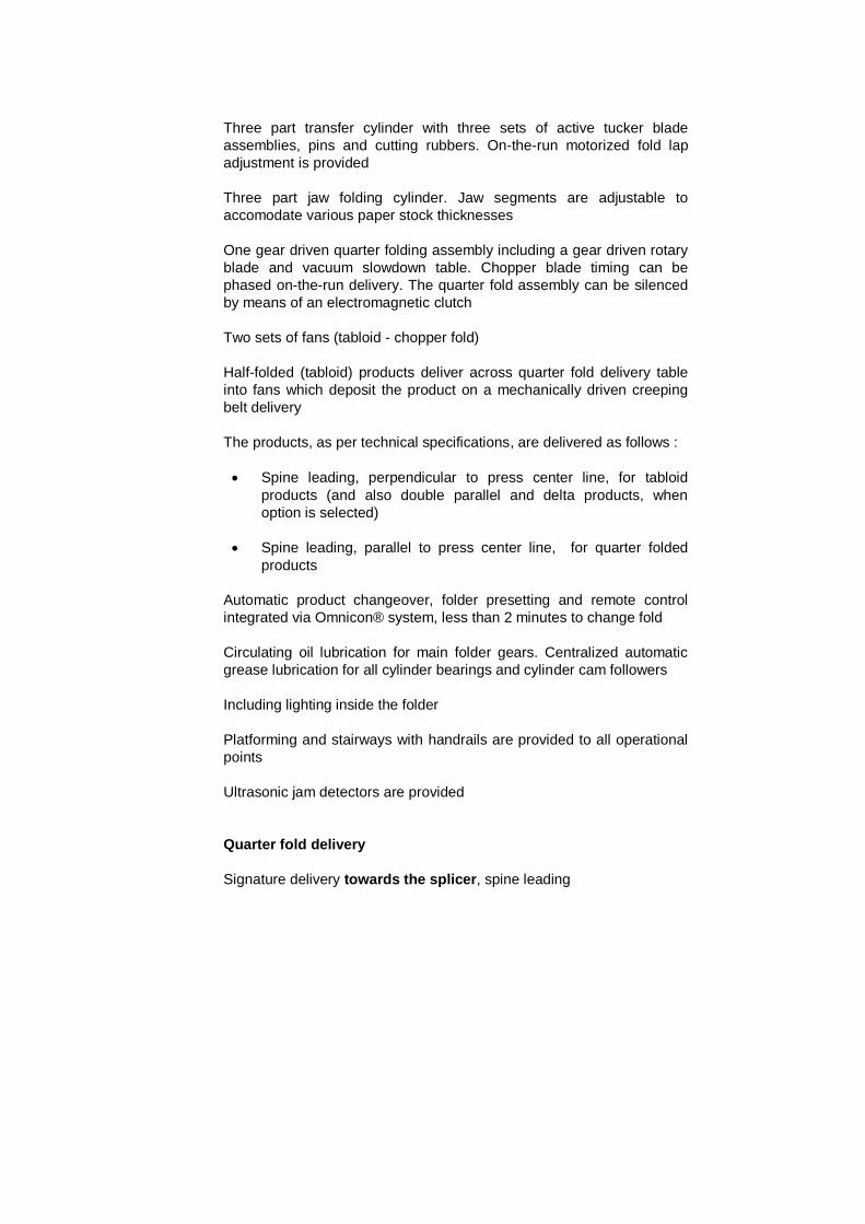
Three part transfer cylinder with three sets of active tucker blade
assemblies, pins and cutting rubbers. On-the-run motorized fold lap
adjustment is provided
Three part jaw folding cylinder. Jaw segments are adjustable to
accomodate various paper stock thicknesses
One gear driven quarter folding assembly including a gear driven rotary
blade and vacuum slowdown table. Chopper blade timing can be
phased on-the-run delivery. The quarter fold assembly can be silenced
by means of an electromagnetic clutch
Two sets of fans (tabloid - chopper fold)
Half-folded (tabloid) products deliver across quarter fold delivery table
into fans which deposit the product on a mechanically driven creeping
belt delivery
The products, as per technical specifications, are delivered as follows :
Spine leading, perpendicular to press center line, for tabloid
products (and also double parallel and delta products, when
option is selected)
Spine leading, parallel to press center line, for quarter folded
products
Automatic product changeover, folder presetting and remote control
integrated via Omnicon® system, less than 2 minutes to change fold
Circulating oil lubrication for main folder gears. Centralized automatic
grease lubrication for all cylinder bearings and cylinder cam followers
Including lighting inside the folder
Platforming and stairways with handrails are provided to all operational
points
Ultrasonic jam detectors are provided
Quarter fold delivery
Signature delivery towards the splicer, spine leading

SPEEDS (SIGNATURES PER HOUR) AND ACCURACIES (mm) - JF-55
TABLOID Paper weight
1 x 4 p
½ web 1 x 8 p 1 web
1 x 16 p 2 webs
32-39 g/m
2 (22-26 lbs)
35 000
± 0.3 / ± 0.5 45 000
± 0.3 / ± 0.5
40-55 g/m2 (27-37 lbs) 31 000
± 0.3 / ± 0.5 45 000
± 0.3 / ± 0.5 50 000
± 0.4 / ± 0.6
56-71 g/m2 (38-48 lbs) 40 000
± 0.3 / ± 0.5 55 000
± 0.4 / ± 0.6 55 000
± 0.4 / ± 0.6
72-89 g/m2 (49-60 lbs) 40 000
± 0.3 / ± 0.5 55 000
± 0.4 / ± 0.6 50 000
± 0.5 / ± 0.7
90-114 g/m2 (61-77 lbs) 43 000
± 0.3 / ± 0.5 50 000
± 0.4 / ± 0.6 50 000
± 0.5 / ± 0.7
115-135 g/m2 (78-91 lbs)
43 000
± 0.4 / ± 0.6 50 000
± 0.4 / ± 0.6 50 000
± 0.5 / ± 0.7
Fold accuracy : Spine with first cross perforation - Spine without first
cross perforation
Fold accuracy : Spine with linear perforation - Spine without linear
perforation
Important : These performances are those of a JF-55 folder equipped
with Vacucontrol, chopper fold moistening system and fold perforations
other than those specifically considered. The folder must be in good
running conditions (correct settings, good mechanical conditions).
Speed and accuracy are associated to coated paper, type LWC, MWC
and equivalent. The web width must be in compliance with folder pin,
gripper and tape positioning. Half of the total tolerance value is the
standard deviation from the mean
MAGAZINE Paper weight
1 x 8 p ½ web
1 x 16 p 1 web
1 x 16 p 2 webs
32-39 g/m
2 (22-26 lbs)
40 000
± 0.4 / ± 0.6 45 000
± 0.4 / ± 0.6
40-55 g/m2 (27-37 lbs) 36 000
± 0.4 / ± 0.8 48 000
± 0.3 / ± 0.5 50 000
± 0.4 / ± 0.6
56-71 g/m2 (38-48 lbs) 40 000
± 0.3 / ± 0.6 55 000
± 0.4 / ± 0.6 55 000
± 0.4 / ± 0.7
72-89 g/m2 (49-60 lbs) 40 000
± 0.3 / ± 0.6 55 000
± 0.4 / ± 0.6 50 000
± 0.4 / ± 0.7
90-114 g/m2 (61-77 lbs) 40 000
± 0.3 / ± 0.6 50 000
± 0.4 / ± 0.6 45 000
± 0.4 / ± 0.8
115-135 g/m2 (78-91 lbs)
40 000
± 0.3 / ± 0.6 45 000
± 0.4 / ± 0.6 40 000
± 0.5 / ± 0.8

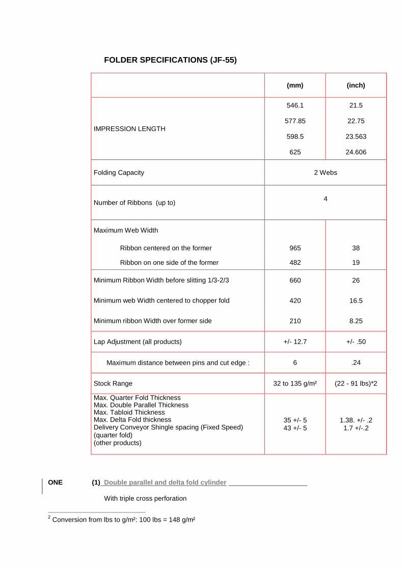
FOLDER SPECIFICATIONS (JF-55)
(mm) (inch)
IMPRESSION LENGTH
546.1 21.5
577.85 22.75
598.5 23.563
625 24.606
Folding Capacity 2 Webs
Number of Ribbons (up to) 4
Maximum Web Width
Ribbon centered on the former 965 38
Ribbon on one side of the former 482 19
Minimum Ribbon Width before slitting 1/3-2/3 660 26
Minimum web Width centered to chopper fold 420 16.5
Minimum ribbon Width over former side 210 8.25
Lap Adjustment (all products) +/- 12.7 +/- .50
Maximum distance between pins and cut edge : 6 .24
Stock Range 32 to 135 g/m² (22 - 91 lbs)*1
Max. Quarter Fold Thickness Max. Double Parallel Thickness Max. Tabloid Thickness Max. Delta Fold thickness Delivery Conveyor Shingle spacing (Fixed Speed) (quarter fold) (other products)
35 +/- 5 43 +/- 5
1.38. +/- .2 1.7 +/-.2
ONE (1) Paper lead assembly with angle bars for two webs
The paper lead includes :
1 Conversion from lbs to g/m²: 100 lbs = 148 g/m²
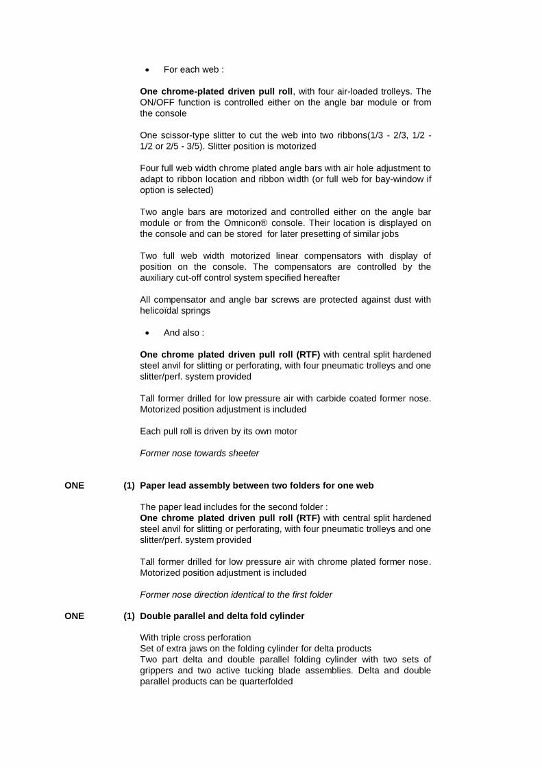
For each web :
One chrome-plated driven pull roll, with four air-loaded trolleys. The
ON/OFF function is controlled either on the angle bar module or from
the console
One scissor-type slitter to cut the web into two ribbons(1/3 - 2/3, 1/2 -
1/2 or 2/5 - 3/5). Slitter position is motorized
Four full web width chrome plated angle bars with air hole adjustment to
adapt to ribbon location and ribbon width (or full web for bay-window if
option is selected)
Two angle bars are motorized and controlled either on the angle bar
module or from the Omnicon® console. Their location is displayed on
the console and can be stored for later presetting of similar jobs
Two full web width motorized linear compensators with display of
position on the console. The compensators are controlled by the
auxiliary cut-off control system specified hereafter
All compensator and angle bar screws are protected against dust with
helicoïdal springs
And also :
One chrome plated driven pull roll (RTF) with central split hardened
steel anvil for slitting or perforating, with four pneumatic trolleys and one
slitter/perf. system provided
Tall former drilled for low pressure air with carbide coated former nose.
Motorized position adjustment is included
Each pull roll is driven by its own motor
Former nose towards sheeter
ONE (1) Paper lead assembly between two folders for one web
The paper lead includes for the second folder :
One chrome plated driven pull roll (RTF) with central split hardened
steel anvil for slitting or perforating, with four pneumatic trolleys and one
slitter/perf. system provided
Tall former drilled for low pressure air with chrome plated former nose.
Motorized position adjustment is included
Former nose direction identical to the first folder
ONE (1) Double parallel and delta fold cylinder
With triple cross perforation
Set of extra jaws on the folding cylinder for delta products
Two part delta and double parallel folding cylinder with two sets of
grippers and two active tucking blade assemblies. Delta and double
parallel products can be quarterfolded

All double parallel and delta signatures are delivered spine leading
perpendicular to the press centerline
SPEEDS (SIGNATURES PER HOUR) AND ACCURACIES (mm) - JF-55
DIGEST TWO-ON
Paper weight
2 x 8 p
½ Web
2 x 16 p
1 Web
2 x 32 p
2 Webs
32-39 g/m2 (22-26 lbs) 40 000 45 000
± 0.4 / ± 0.6 ± 0.4 / ± 0.6
40-55 g/m2(27-37 lbs) 40 000 45 000 50 000
± 0.4 / ± 0.6 ± 0.4 / ± 0.6 ± 0.5 / ± 0.8
56-71 g/m2 (38-48 lbs) 45 000 55 000 50 000
± 0.4 / ± 0.6 ± 0.5 / ± 0.7 ± 0.5 / ± 0.8
72-89 g/m2 (49-60 lbs) 45 000 55 000 50 000
± 0.4 / ± 0.6 ± 0.5 / ± 0.7 ± 0.5 / ± 0.8
90-114 g/m2 (61-77 lbs) 45 000 50 000 40 000
± 0.4 / ± 0.6 ± 0.5 / ± 0.8 ± 0.6 / ± 1.0
115-135 g/m2 (78-91 lbs) 40 000 46 000 38 000 (1)
± 0.4 / ± 0.6 ± 0.5 / ± 0.8 ± 0.6 / ± 1.0
Fold accuracy : Spine with second cross perforation - Spine without
second cross perforation
(1) : 115-120 g/m² only
CHOPPED DELTA
Paper weight
1 x 12 p
½ Web
1 x 24 p
1 Web
32-39 g/m2 (22-26 lbs) 35 000
± 0.6/ ± 0.8
40-55 g/m2(27-37 lbs) 35 000 40 000
± 0.6 / ± 0.8 ± 0.6 / ± 0.8
56-71 g/m2 (38-48 lbs) 40 000 45 000
± 0.6 / ± 0.8 ± 0.6 / ± 0.8
72-89 g/m2 (49-60 lbs) 40 000 45 000
± 0.6 / ± 0.8 ± 0.6 / ± 0.8
90-114 g/m2 (61-77 lbs) 40 000 45 000
± 0.6 / ± 0.8 ± 0.6/ ± 0.8
115-135 g/m2 (78-91 lbs) 45 000 40 000
± 0.6 / ± 0.8 ± 0.6 / ± 1
Fold accuracy : Spine with second cross perforation - Spine without
second cross perforation
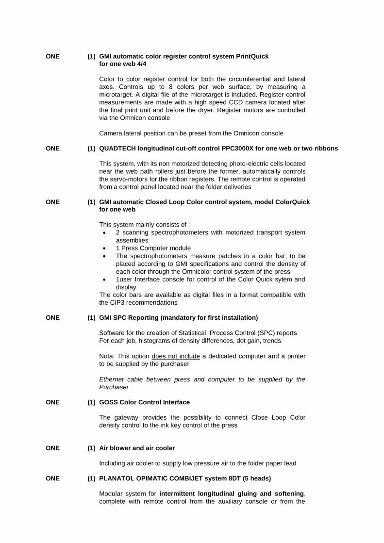
ONE (1) GMI automatic color register control system PrintQuick for one web 4/4
Color to color register control for both the circumferential and lateral
axes. Controls up to 8 colors per web surface, by measuring a
microtarget. A digital file of the microtarget is included. Register control
measurements are made with a high speed CCD camera located after
the final print unit and before the dryer. Register motors are controlled
via the Omnicon console
Camera lateral position can be preset from the Omnicon console
ONE (1) QUADTECH longitudinal cut-off control PPC3000X for one web or two ribbons
This system, with its non motorized detecting photo-electric cells located
near the web path rollers just before the former, automatically controls
the servo-motors for the ribbon registers. The remote control is operated
from a control panel located near the folder deliveries
ONE (1) GMI automatic Closed Loop Color control system, model ColorQuick for one web
This system mainly consists of :
2 scanning spectrophotometers with motorized transport system
assemblies
1 Press Computer module
The spectrophotometers measure patches in a color bar, to be
placed according to GMI specifications and control the density of
each color through the Omnicolor control system of the press
1user Interface console for control of the Color Quick sytem and
display
The color bars are available as digital files in a format compatible with
the CIP3 recommendations
ONE (1) GMI SPC Reporting (mandatory for first installation)
Software for the creation of Statistical Process Control (SPC) reports
For each job, histograms of density differences, dot gain, trends
Nota: This option does not include a dedicated computer and a printer
to be supplied by the purchaser
Ethernet cable between press and computer to be supplied by the
Purchaser
ONE (1) GOSS Color Control Interface
The gateway provides the possibility to connect Close Loop Color
density control to the ink key control of the press
ONE (1) Air blower and air cooler
Including air cooler to supply low pressure air to the folder paper lead
ONE (1) PLANATOL OPIMATIC COMBIJET system 8DT (5 heads)
Modular system for intermittent longitudinal gluing and softening,
complete with remote control from the auxiliary console or from the

COMBIJET cabinet, also including mounting brackets, bars, hoses and
wires
Memory for 29 product pictures, each with individual glue patterns,
which can be programmed by the operator
Motorized lateral adjustment of the gluing and softening head location
with path measuring and feedback
Feeding of adhesive and fold-softening agent from pressurized tanks,
with a volume of 50 kg each
Contact application with resistant ceramic nozzles
Remote diagnosis system as an option available
ONE (1) GOSS Modular main press drive system
GOSS Modular Main Drive System is specially designed with SIEMENS
for printing press controls and utilizes industry-accepted components
All drives are built to a nominal 400 volts ± 10%, 3 phase, 50Hz
standard (or 460 volts ± 10%, 3 phase, 60Hz) . Values outside this
range may cause equipment damage and/or incorrect press operations,
invalidating the press warranty. Other power supplies can be
accommodated through optional transformer
The press system is provided with individual AC drive motors and
controllers for each unit, each independant chill roll section, slitter roll,
RTF and folder. Controls for individual and group operations are
provided as a part of the Control System
Drive cabinets are delivered tight together in large sub assembly. Each
sub assembly is equipped with its own chilling equipment. Customer is
responsible to supply chilled water as per pre-installation meeting and
documents.
Cabinets are sealed for dust free function (IP54)
ONE (1) Electrical power distribution cabinet
This cabinet includes :
One switchboard section, sized for the press system. It includes a
main switch and individual breakers housed in an enclosure for the
following press components :
Main Drive system, units, chill, paper lead and folder,
Splicer and auto roll loading (when supplied),
Dryer,
Press power distribution
One press power distribution for auxiliaries and post press equipment
- Auxiliary I/O and power distribution enclosure in a prewired enclosure.
Interfaces for the dryer, alarms, auxiliary equipment and the grease
pump are provided to the press I/O system

Note :
Customer has to provide separate power supply for press lighting
(units and folder) and for press plate preparation equipment
Auxiliary equipments connected to the power distribution must
comply with the Main Power Supply voltage. If not, a transformer
may have to be added to the equipment (RFQ)
ONE (1) Communication enclosure (PLC)
It includes all PC, PLC and network connection for the complete press
system
Is also included the UPS (Uninterrupted power supply)
Note : Electrical and electronics equipments are designed for a press
room temperature that should not exceed 45°C (113°F) at the cabinet
location
ONE (1) NELA Pneumatic plate punch for Autoplate and non Autoplate, model HAP
Designed to GOSS INTERNATIONAL specifications and manufactured by NELA
Adapted for units with Autoplate
ONE (1) NELA Semi-automatic plate bender for Autoplate and non Autoplate, model HAO
Designed to GOSS INTERNATIONAL specifications and manufactured
by NELA
Adapted for units with Autoplate
ONE (1) GOSS set of spare parts, List A
ONE (1) Tool box
One set of tools, one set of flat spanners, one set of socket heads,
screw drivers, portable lamp
ONE (1) Small empty console for cut-off control auxiliary equipment
This console is located between the Omnicolor® consoles and
integrates control panels for the color register control
ONE (1) GOSS Omnicon Control system
Press System operation combines functions from Omnicon
Press Control and Color Control System from one Master Press
Console per PRESS
Omnicon Press Control System is PLC based for control of all print,
fold and drive functions
Features include :

Windows NT operating system
Master drive system
Pendant mounted touch screen monitor
Pull out trays for keyboard and mouse
Sequencing of print functions can be automatically or manually
initiated
Remote ink and water control with the added capability to track
press speed
Motorized circumferential and lateral register as well as plate
cylinder skewing are adjusted via touch screen control
Remote infeed tension adjustment with readout of dancer air
cylinder loading, and push button control to allow for engaging or
disengaging of the infeed nips
Good and total counters for folder or sheeter
Press operations and faults displayed through touch screen
monitor
Bar graph display for ink key values as well as on touch screen
Multiple language support
Modem capability for remote diagnostics of press system.
Customer must supply a dedicate telephone line
The Color Control System provides remote adjustment, presetting and
monitoring of ink key position. Operator consoles incorporate a LED
bargraph key position display. A system can consist of up to four
consoles
Features include :
Each console can be configured independently of other consoles
Each console can be configured to control up to eight units (16
inkers)
Supports GROUP and ALL key moves
500 previously run jobs can be recorded and stored on each
console
Remote jobs storage capability with GOSS scanner or Prepress
Gateway
Remote ink/water roll speed control
Remote register control (lateral, circumferential and plate cylinder
skewing)
Fixed top mounted on top of console to hold color “OK” sheets
The press is equipped with :
One Master Omnicon press control console including one color
control
One additional Omnicon press console for the units
ONE (1) Optional Omnicon console with color control
ONE (1) Prepress Interface (PPI) without Job Memory Card Drive
(with Omnicolor consoles)
Interface between digital pre-press systems and the printing press
This system permits the conversion of the area coverage into area
coverage values for the individual ink zones as well as set up of ink
roller speed

Paper type and ink type are used to define the ink profile and the speed
of the ink roller
Data are transferred ON-LINE to the Omnicolor Master Console and
provide precise values for pre-setting of ink keys. Preset values can be
updated after the job is run and stored on the Omnicolor console for
reprinting of job at a later time
Includes the software and an operator manual
All additional hardware (PC, cables and if needed hubs/routers) is to be
supplied by customer, according to GOSS specifications
The prepress interface software runs under Microsoft Windows
2000
The Prepress Interface accepts files only in CIP3 format (version 2.1)
One Prepress Interface works with several presses installed in the same
press hall
ONE (1) HARIG central chiller model KKS 100 (40°) for 4 units for 1 web (55.000 iph)
Two chilled water circuits
Equipment for complete press, consisting of :
Water chill unit with an air cooled condenser for outside placement
Wiring and piping between press and chiller and between chiller and
condenser are not included
ANCILLARY EQUIPMENT APPROVED BY GOSS INTERNATIONAL MONTATAIRE AND
ACQUIRED BY THE PURCHASER
1. Should the PURCHASER directly purchase any ancillary equipment to be used in conjunction
with the GOSS press, a full description must be given below, in order to ensure that it is
compatible with the machinery supplied by the SELLER.
2. The specifications and the precise supply limits and safety norms of all the items of ancillary
equipment listed below must reach GOSS INTERNATIONAL MONTATAIRE no later than 4
weeks after the Sales Agreement is signed. Failure to meet this dead line could result in
delayed shipment of the press.
3. In the case of any ancillary equipment purchased directly by the PURCHASER, all adjustments,
and the expenses arising therefrom, and the necessary mechanical and electrical connecting
parts shall be provided by the PURCHASER and at its expense.
4. In the case of any equipment acquired directly by the PURCHASER, the interfaces (including
the cables, consoles, controls and platforms), the installation, commissioning and the
guarantee obligations in respect of this equipment are excluded from the obligations of GOSS
INTERNATIONAL MONTATAIRE.
5. The safety responsability for these equipments will be born by the PURCHASER.
6. List of equipment :
Equipment Quantity Manufacturer References
None
ANCILLARY EQUIPMENT NOT APPROVED BY GOSS INTERNATIONAL MONTATAIRE AND
ACQUIRED BY THE PURCHASER
1. It is standard procedure at GOSS INTERNATIONAL MONTATAIRE for the Research
Department and the Product Department to approve all equipment used on a GOSS press,
particularly where its use can affect the overall performance of the machine or the safety rules.
Such approval has not been granted to the ancillary equipment listed below.
2. In the case of any ancillary equipment acquired directly by the PURCHASER, all adjustments
and the necessary connecting parts shall be for the account of the PURCHASER.
3. In the case of any equipment acquired directly by the PURCHASER, the interfaces (including
the cables, consoles, controls and platforms), the installation, commissioning and the
guarantee obligations in respect of this equipment are excluded from the obligations of GOSS
INTERNATIONAL MONTATAIRE.
4. It is clearly understood that GOSS INTERNATIONAL MONTATAIRE cannot be held liable for
any damage or accidents which may result from the use or operation of this equipment.
5. Where a non-approved item of equipment is specified by the PURCHASER,GOSS
INTERNATIONAL MONTATAIRE do not guarantee the overall performance of the press.
6. List of equipment :
Equipment Quantity Manufacturer References
None

ANCILLARY EQUIPMENT NOT APPROVED BY GOSS INTERNATIONAL MONTATAIRE AND
SOLD WITH THE MACHINE
1. It is standard procedure at GOSS INTERNATIONAL MONTATAIRE for the Research
Department and the Product Department to approve all equipment used on a GOSS press,
particularly where its use can affect the overall performance of the machine or the safety rules.
Such approval has not been granted to the ancillary equipment listed below.
2. Where a non-approved item of equipment is specified by the PURCHASER, GOSS
INTERNATIONAL MONTATAIRE do not guarantee the overall performance of the press and
any damage or accident which may result from the use or operation of this equipment.
3. List of equipment :
Equipment Quantity Manufacturer References
None
SPECIFICATION OF PLATE PUNCH
The MACHINERY is delivered with a plate punch and a plate bender in conformity with the
drawing of standard GOSS plate.
If the PURCHASER wants special perforations, the PURCHASER must provide one of the
following pieces of information (mylar or standard plate used by the PURCHASER) in order to
ensure that the plate bending and perforating system is properly compatible with the plating-up
system on the plate cylinders.
This information has to be returned to the SELLER no later than 4 months before the contractual
shipment date.
Should there be an error or delay in the specifications provided, the SELLER cannot be held
responsible for the delay and additional cost incurred.
CTP (Computer To Plate) COMPATIBILITY
In order to check the positioning of plates by the CTP system is compatible with the SELLER's specifications (punching and bending), and to obtain the best results for the color register control and the plate cocking; the PURCHASER undertakes to provide the exact references of the CTP system used by the PURCHASER within 15 days after contract signature (filling in the specific CTP supplied document - see following pages). Based on this information, the SELLER shall confirm whether the CTP system is compatible and whether an optimum use of the insolation-punching-bending process is possible

CHECK LIST : COMPUTER TO PRESS DATE :
Customer : Press n° :
Printing :
Project of press :
Type of press already installed in the customer plant .... Check
list
Computer to film :
Manufacturer ..................................
Model ..............................................
Dimensions maxi-mini of the films
Computer to plate :
Manufacturer ...................................
Model
Dimensions of the CTP punches ...
Dimensions maxi-mini of the plate .
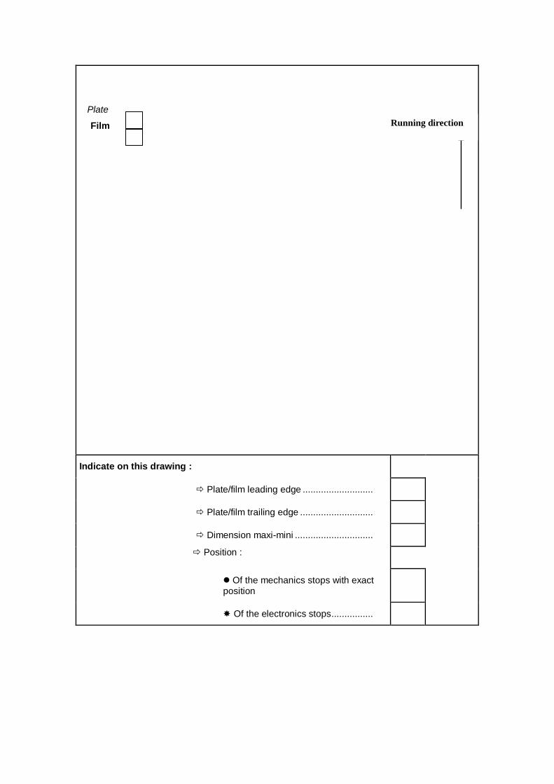
Drawing showing the position of the plate/film in the CTP :
Drawing hereafter completed
Compatibility with other presses :
Yes
No
Plate drawing of other presses :
Press inking pre-adjustment:
1). By the plate scanner :
Yes
No
Supplier plate dimension maxi-mini
Model
2). By direct connections to the press :
Yes
No
Model

Plate
Film
Indicate on this drawing :
Plate/film leading edge ...........................
Plate/film trailing edge ............................
Dimension maxi-mini ..............................
Position :
Of the mechanics stops with exact position
Of the electronics stops ................
Mini
Maxi
Dimension
Dim
ensio
n
Max
i
Min
i
Running direction

GAS SPECIFICATION FOR DRYER
The PURCHASER must specify the following information in order to ensure that the drying
equipment included in the Agreement is compatible with the type of gas supplied.
This specification sheet shall be completed and returned to the SELLER no later than 4 months
before the contractual shipment date.
Should there be an error or delay in the specifications given below, the SELLER cannot be held
responsible for the delay and additional cost incurred.
1. Type of fuel :
2. Calorific value :
3. Gas pressure available in printing works :
4. Pressure to be delivered to dryer :
5. Chemical analysis of gas :
N.B. :
Depending on the type of gas, any additional cost shall be charged to the PURCHASER in case
the specifications are given after the signature of the present Agreement.

Appendix A1
ONE GOSS MODEL M-600 C
WEB OFFSET PRINTING PRESS
WITH 4 UNITS 1 WEB WITH ONE JF-55 FOLDER
SLAVE press
Cut-off length 625 mm
Maximum transfer area 618 x 960 mm
Maximum web width 965 mm
Maximum printing speed up
to
55 000 IPH*
Maximum web speed 9.55 m/s
Power supply 400 Volts ± 10%
3 Phases + Earth
50 Hertz
All the equipment connected to the main control must be designed for the
above power supply
Ancillary equipment in current contract and not manufactured by the SELLER
is in accordance with specifications in force at the time of contract signature
* Note : Maximal speeds are given for coated paper type LWC, MWC or
equivalent ; speeds vary according to production characteristics (paper weight,
fold type, ink coverage) and are specified in the charts or sketches of elements
of the press (dryer, folder, sheeter, …)
Actual production speed depends on elements unrelated with the inherent
performances of the press (adequat environment, correct maintenance, crew
skills, selection of consumables)
See clause 9 (h) of General Sales Conditions

FOUR (4) GOSS Blanket to blanket printing units
Extremely rigid construction with box type frame on the gear side and
large dimensioned spacers
In-line stacked cylinder arrangement. Cylinders are all mounted on
special bearings providing maximum vibration absorption
The units are driven by individual motors (one AC drive per unit)
The plate cylinder can be automatically rotated to a fixed position to
facilitate plate-up
Chrome plated plate cylinders fitted with 40 mm wide hardened steel
bearers. Plate cylinder undercut is 0.27 mm for a 0.30 mm aluminium
plate and is equipped with a pneumatic plate lock-up device
Plate cylinder positioning is controlled from the Omnicon console,
allowing rapid plate change
The four register adjustments consist of motorized lateral ( 2 mm),
motorized circumferential ( 3 mm), motorized plate cocking ( 0.3 mm).
Unit phasing register is obtained by unit drive synchronisation
Each printing unit can be individually silenced
Platforms between the units allowing plates to be mounted or removed
easily, the web staying in the machine
Inking :
Large ink fountain with remote control of ink keys
The inking system can be converted from a 100-0-0 to a 80-10-10 split
by means of a mechanical changeover of one roller
Each inker can be silenced independently with or without the operation
of the dampener system. The upper and lower print couples can be
declutched independently of each other
Inking is ensured by a total of 15 large diameter rollers
Each inker includes :
one ceramic ink fountain roller
one nylon covered pick-up roller
one nylon roller
three nylon covered oscillating vibrators
five rubber covered distributor rollers
three rubber covered form rollers (two are self-oscillating)
one rubber covered rider roller
The vibrators are cooled by means of water circulation
All form rollers follow plate cylinder skewing (form roll following)

Two GOSS pneumatic ink scraping blades are provided per unit
Dampening
Convertible dampening system with sliding contact roller with pneumatic
switching between the two modes of dampening (film or emulsification)
from the main Omnicon console
Each dampener includes :
One rubber covered pan roller
One chrome plated metering roller with special surface treatment and
cocking adjustment
One self-oscillating rubber dampener form roller
One chrome plated jockey roller
Each unit includes an integrated filtering assembly in the dampening
water circuit
The GOSS dampening system is designed for a high quality printing on
coated or semi coated paper
Other equipment
A motor driven oil pump provides pressurized circulation as well as
cascade lubrication of gears, unit clutches, oscillating mechanism, and
all cylinder bearings. Oil cooling is provided through a heat exchanger
and oil flow and temperature are monitored, indicated, and the press is
stopped in the event of an oil flow failure
A motorized bypass web lead for systems with more than one web is
provided. The web-up rolls under the units included are as follows :
5 units : bypass under the first unit after the infeed
Platforms between units are hinged and pneumatically actuated
Unit guarding is controlled by safety switches
Ink piping along the printing unit gearside is provided for 4 colors. Hand
valves are provided at each unit. Ink levelers are optional
Bustle wheels are provided. Three wheels per unit are provided on all
units, except the first unit in each unit group (i.e., on units 2, 3, 4, 5, and
6 on a six unit-one web press or units 2, 3, 4, and 6, 7, 8, of an 8 unit-
two web press)
Each unit is supplied with two blankets
Set of web break detectors :

GOSS web break detectors are interfaced with GOSS Omnicon®
system to provide first out indication and self-arming interlocks, and
severer/web catcher interface with web break detectors
GOSS web break detectors are installed at the exit of each unit, inside
and after the chill roll section.
ONE (1) Space for printing unit installed at a later date
This space is located after the splicer and includes two extra rollers and
brackets in S-wrap configuration
The electrical supply is upgraded for this future retrofit
ONE (1) Set of spare covered rolls for one half unit
Includes covered rolls for dampening and inking system for one half unit
EIGHT (8) Spare blanket(s)
ONE (1) Stacked Duplex Press configuration with Dual Power Distribution
Control system that allows the stacked unit arrangement to operate as
two independent press lines or together. Conventional duplex
arrangements include at least two folders
Configuration includes per press one switchboard and one drive
enclosure and for the total system one additional Slave Main Press
Console
Substructure for upper press, as per Seller’s recommendations, must be
provided by the PURCHASER.
ONE (1) Autoplate device for four units
The two plate cylinders of each unit are equipped with an automatic
plate-up system including :
One upper retractable rack for one new plate
One lower side movable rack for one new plate
One pneumatically activated automatic tensioning system
This system allows to change the plate without breaking the web
The plate cylinders have no underpacking
The maximum paper stock is 135 g/m2
with 0.30 mm thickness plates
and up to 200 g/m2
with 0.35 mm thickness plates
Autoplate mechanisms are designed to fullfil their functions only if
handled in proper manner. They are not designed to withstand other

constraints. Therefore it is obviously prohibited to load them with any
extra weights
Correct function of such a system is warranted only if cleanliness and
maintenance are insured by the printer as per operator manual
ONE (1) Set of connecting parts for BALDWIN blanket cleaner integration for 4 units
ONE (1) BALDWIN automatic blanket cleaner model Impact for 4 units
Electronically controlled wash-up procedure, with the possibility of
preselecting ten different wash-up programs. Automatic advance of
wash-up cloth
Impact system uses pre-soaked tissue rolls
Controlled from the unit Omnicon console
Two wash-up bars per perfecting unit, placed on the infeed side of the
unit
Three Prepac impregnated wash cloth rolls are supplied with each
washer
ONE (1) Circulator and temperature control for reduced Alcohol printing (<10 % alcohol) TECHNOTRANS Gamma.c 600 combination unit for dampening solution cooling and ink roller temperature control for 5 units
Integrated in one cabinet. Water cooled chiller for dampening solution
circuit and ink roller temperature control circuit for connection to a
central chill water supply
Dampening solution circuit :
Stainless steel tank with integrated filter box
One circulation and one feed pump
Integrated additive mixer type aquados.d 5
Intermediate tank located near the last unit for return of the dampening
solution from the press to the delta.c unit
Conductivity display on the circulator cabinet
Ink roller temperature control circuit :
The system works in closed loop circuit
Electrical heating, for cold press start up
Circulation pump
Motor valves for temperature regulation of the return water coming back
from the ink rollers
ONE (1) TECHNOTRANS pH value indication
Display on the Tecon panel of the circulator cabinet

ONE (1) GOSS patented active web catcher
This system is fired by a web break detection system and catches the
web via an air knife and two catching rollers in case of web break in the
dryer or after the dryer (linked to Ecocool detection)
The system is installed between last printing unit and dryer
The efficiency rate of the system is above 90%
ONE (1) GOSS CONTIWEB dryer with integrated afterburner and Chill roll section ECOCOOL®/T 93-1020 for one web max. speed 10.7 m/s (2110 fpm) for 90 gsm (61 lbs) paperweight max. speed 8.6 m/s (1700 fpm) for 135 gsm (91 lbs) paperweight
The Ecocool/T dryer is a web offset dryer with the functions of drying,
chilling and guiding the web integrated in one single system
In the dryer section (Ecotherm concept with integrated afterburner) the
printed web will be dried at low air temperatures. The dryer makes direct
use of the energy contained in the solvents in the system by means of
active concentration control. In the thermal afterburners the solvents are
burnt to produce hot clean air. The solvent concentration is controlled
through constant temperature and pressure measurements, steering the
frequency controlled fans. The result is a reduction of the gas
consumption depending on ink coverage, paperweight and speed
The Ecocool system includes small-diameter chill rolls positioned very
close to the exit of the drying section. This allows better contact of the
web to the chill rolls, which increases efficiency and eliminates solvent
condensation
The web guide on the first chill roll makes this excellent concept
complete
In the cooling zone the web temperature is reduced at the dryer outlet
by approximately 40oC (72
oF)
During production stops the dryer is kept at Stand-By temperature for
quick restart
Standard equipment and construction features :
The Ecocool dryer is supplied as one complete unit
Comply with the latest standards EN 1539, NFPA 86 and the
directives of the VDI
Three temperature zones : heating zone, drying zone, cooling
zone and a chill section
The air circulation system provides a high air volume to the
patented "Crossjet" air nozzle bars
Web temperature control by infrared camera, located between
drying zone and cooling zone
Two afterburner installations with heat exchangers and frequency
controlled fans
Door sensors for safety
Nine small diameter chill rolls of which the fourth roll is driven
by a frequency controlled AC motor
Contiweb web guide system and web break detection
Web tension measurement at the last roller
Silicone applicator, before the first and the second chill roll,
including reservoir and mixer, and including independent speed
control of the silicone rollers

One basic water piping system including valve, pump and filter
Modem connection for remote diagnosis system, customer to
provide dedicated telephone line
Minimum dynamic gas pressure (note) : 100 mbar 1.45 psi
Maximum static gas pressure : 330 mbar 4.8 psi
Gas type different from natural gas on request
The performance of the dryer is as diagram showing speed limitation
according to paper weight and ink coverage
ONE (1) GOSS CONTIWEB Remoistening & Advanced Silicone package for one web
The Remoistening & Advanced Silicone Package consists of :
The controls on the Silicon Applicators
The silicone applicator will be equipped with small mix tanks for each
silicone roller. Silicone oil out of the reservoir with the concentrated
silicone and water are mixed in these small tanks for each applicator.
The amount of silicone oil coverage and water can be controlled
separately for each side of the web. All components are integrated in
the Ecocool
Remoistening system
The absolute moisture content in the product after remoistening can be
as high as 4,5%. Normal moisture values are in the range of 3.5 %.
Note: remoistening system is integrated in the silicone applicator and
controls
ONE (1) GOSS CONTIWEB Webbing-up chain for Ecocool/T 93 for one web
ONE (1) GOSS Multiple combination folder model JF-55™ for one web
The basic JF-55™ folder is a single width combination folder with one
rotary chopper fold assembly featuring very high production speeds
and a single stream delivery for magazine products and a single stream
delivery for tabloid products. It can produce at speeds of up to 55 000
iph and consists of the following features :
Lower folder :
Forming rolls are provided at the former nose and are horizontally and
vertically adjustable
Two sets (upper and lower) of driven, 178 mm wide, air-loaded
urethane pinch pulleys
Circumferential perforator/scorer (in-line) mounted between the two sets
of pinch pulleys and actuated via air cylinder. On-the-run depth and
lateral adjustment is provided
Cross perforator cylinders with on-the-run circumferential phasing and
depth adjustment
One part cutting cylinder with one knife box fitted with soft cheekwoods
Three part transfer cylinder with three sets of active tucker blade
assemblies, pins and cutting rubbers. On-the-run motorized fold lap
adjustment is provided
Three part jaw folding cylinder. Jaw segments are adjustable to
accomodate various paper stock thicknesses
One gear driven quarter folding assembly including a gear driven rotary
blade and vacuum slowdown table. Chopper blade timing can be
phased on-the-run delivery. The quarter fold assembly can be silenced
by means of an electromagnetic clutch
Two sets of fans (tabloid - chopper fold)
Half-folded (tabloid) products deliver across quarter fold delivery table
into fans which deposit the product on a mechanically driven creeping
belt delivery
The products, as per technical specifications, are delivered as follows :
Spine leading, perpendicular to press center line, for tabloid
products (and also double parallel and delta products, when
option is selected)
Spine leading, parallel to press center line, for quarter folded
products
Automatic product changeover, folder presetting and remote control
integrated via Omnicon® system, less than 2 minutes to change fold
Circulating oil lubrication for main folder gears. Centralized automatic
grease lubrication for all cylinder bearings and cylinder cam followers
Including lighting inside the folder
Platforming and stairways with handrails are provided to all operational
points
Ultrasonic jam detectors are provided
Quarter fold delivery
Signature delivery towards the splicer, spine leading

SPEEDS (SIGNATURES PER HOUR) AND ACCURACIES (mm) - JF-55
TABLOID Paper weight
1 x 4 p
½ web 1 x 8 p 1 web
1 x 16 p 2 webs
32-39 g/m
2 (22-26 lbs)
35 000
± 0.3 / ± 0.5 45 000
± 0.3 / ± 0.5
40-55 g/m2 (27-37 lbs) 31 000
± 0.3 / ± 0.5 45 000
± 0.3 / ± 0.5 50 000
± 0.4 / ± 0.6
56-71 g/m2 (38-48 lbs) 40 000
± 0.3 / ± 0.5 55 000
± 0.4 / ± 0.6 55 000
± 0.4 / ± 0.6
72-89 g/m2 (49-60 lbs) 40 000
± 0.3 / ± 0.5 55 000
± 0.4 / ± 0.6 50 000
± 0.5 / ± 0.7
90-114 g/m2 (61-77 lbs) 43 000
± 0.3 / ± 0.5 50 000
± 0.4 / ± 0.6 50 000
± 0.5 / ± 0.7
115-135 g/m2 (78-91 lbs)
43 000
± 0.4 / ± 0.6 50 000
± 0.4 / ± 0.6 50 000
± 0.5 / ± 0.7
Fold accuracy : Spine with first cross perforation - Spine without first
cross perforation
Fold accuracy : Spine with linear perforation - Spine without linear
perforation
Important : These performances are those of a JF-55 folder equipped
with Vacucontrol, chopper fold moistening system and fold perforations
other than those specifically considered. The folder must be in good
running conditions (correct settings, good mechanical conditions).
Speed and accuracy are associated to coated paper, type LWC, MWC
and equivalent. The web width must be in compliance with folder pin,
gripper and tape positioning. Half of the total tolerance value is the
standard deviation from the mean
MAGAZINE Paper weight
1 x 8 p ½ web
1 x 16 p 1 web
1 x 16 p 2 webs
32-39 g/m
2 (22-26 lbs)
40 000
± 0.4 / ± 0.6 45 000
± 0.4 / ± 0.6
40-55 g/m2 (27-37 lbs) 36 000
± 0.4 / ± 0.8 48 000
± 0.3 / ± 0.5 50 000
± 0.4 / ± 0.6
56-71 g/m2 (38-48 lbs) 40 000
± 0.3 / ± 0.6 55 000
± 0.4 / ± 0.6 55 000
± 0.4 / ± 0.7
72-89 g/m2 (49-60 lbs) 40 000
± 0.3 / ± 0.6 55 000
± 0.4 / ± 0.6 50 000
± 0.4 / ± 0.7
90-114 g/m2 (61-77 lbs) 40 000
± 0.3 / ± 0.6 50 000
± 0.4 / ± 0.6 45 000
± 0.4 / ± 0.8
115-135 g/m2 (78-91 lbs)
40 000
± 0.3 / ± 0.6 45 000
± 0.4 / ± 0.6 40 000
± 0.5 / ± 0.8
FOLDER SPECIFICATIONS (JF-55)
(mm) (inch)
IMPRESSION LENGTH
546.1 21.5
577.85 22.75
598.5 23.563
625 24.606
Folding Capacity 2 Webs
Number of Ribbons (up to) 4
Maximum Web Width
Ribbon centered on the former 965 38
Ribbon on one side of the former 482 19
Minimum Ribbon Width before slitting 1/3-2/3 660 26
Minimum web Width centered to chopper fold 420 16.5
Minimum ribbon Width over former side 210 8.25
Lap Adjustment (all products) +/- 12.7 +/- .50
Maximum distance between pins and cut edge : 6 .24
Stock Range 32 to 135 g/m² (22 - 91 lbs)*2
Max. Quarter Fold Thickness Max. Double Parallel Thickness Max. Tabloid Thickness Max. Delta Fold thickness Delivery Conveyor Shingle spacing (Fixed Speed) (quarter fold) (other products)
35 +/- 5 43 +/- 5
1.38. +/- .2 1.7 +/-.2
ONE (1) Double parallel and delta fold cylinder
With triple cross perforation
2 Conversion from lbs to g/m²: 100 lbs = 148 g/m²

Set of extra jaws on the folding cylinder for delta products
Two part delta and double parallel folding cylinder with two sets of
grippers and two active tucking blade assemblies. Delta and double
parallel products can be quarterfolded
All double parallel and delta signatures are delivered spine leading
perpendicular to the press centerline
SPEEDS (SIGNATURES PER HOUR) AND ACCURACIES (mm) - JF-55
DIGEST TWO-ON
Paper weight
2 x 8 p
½ Web
2 x 16 p
1 Web
2 x 32 p
2 Webs
32-39 g/m2 (22-26 lbs) 40 000 45 000
± 0.4 / ± 0.6 ± 0.4 / ± 0.6
40-55 g/m2(27-37 lbs) 40 000 45 000 50 000
± 0.4 / ± 0.6 ± 0.4 / ± 0.6 ± 0.5 / ± 0.8
56-71 g/m2 (38-48 lbs) 45 000 55 000 50 000
± 0.4 / ± 0.6 ± 0.5 / ± 0.7 ± 0.5 / ± 0.8
72-89 g/m2 (49-60 lbs) 45 000 55 000 50 000
± 0.4 / ± 0.6 ± 0.5 / ± 0.7 ± 0.5 / ± 0.8
90-114 g/m2 (61-77 lbs) 45 000 50 000 40 000
± 0.4 / ± 0.6 ± 0.5 / ± 0.8 ± 0.6 / ± 1.0
115-135 g/m2 (78-91 lbs) 40 000 46 000 38 000 (1)
± 0.4 / ± 0.6 ± 0.5 / ± 0.8 ± 0.6 / ± 1.0
Fold accuracy : Spine with second cross perforation - Spine without
second cross perforation
(1) : 115-120 g/m² only
CHOPPED DELTA
Paper weight
1 x 12 p
½ Web
1 x 24 p
1 Web
32-39 g/m2 (22-26 lbs) 35 000
± 0.6/ ± 0.8
40-55 g/m2(27-37 lbs) 35 000 40 000
± 0.6 / ± 0.8 ± 0.6 / ± 0.8
56-71 g/m2 (38-48 lbs) 40 000 45 000
± 0.6 / ± 0.8 ± 0.6 / ± 0.8
72-89 g/m2 (49-60 lbs) 40 000 45 000
± 0.6 / ± 0.8 ± 0.6 / ± 0.8
90-114 g/m2 (61-77 lbs) 40 000 45 000
± 0.6 / ± 0.8 ± 0.6/ ± 0.8
115-135 g/m2 (78-91 lbs) 45 000 40 000
± 0.6 / ± 0.8 ± 0.6 / ± 1

Fold accuracy : Spine with second cross perforation - Spine without
second cross perforation
ONE (1) GMI automatic color register control system PrintQuick for one web 4/4
Color to color register control for both the circumferential and lateral
axes. Controls up to 8 colors per web surface, by measuring a
microtarget. A digital file of the microtarget is included. Register control
measurements are made with a high speed CCD camera located after
the final print unit and before the dryer. Register motors are controlled
via the Omnicon console
Camera lateral position can be preset from the Omnicon console
ONE (1) QUADTECH longitudinal cut-off control PPC3000X for one web or two ribbons
This system, with its non motorized detecting photo-electric cells located
near the web path rollers just before the former, automatically controls
the servo-motors for the ribbon registers. The remote control is operated
from a control panel located near the folder deliveries
ONE (1) GMI automatic Closed Loop Color control system, model ColorQuick for one web
This system mainly consists of :
2 scanning spectrophotometers with motorized transport system
assemblies
1 Press Computer module
The spectrophotometers measure patches in a color bar, to be
placed according to GMI specifications and control the density of
each color through the Omnicolor control system of the press
1user Interface console for control of the Color Quick sytem and
display
The color bars are available as digital files in a format compatible with
the CIP3 recommendations
ONE (1) Connection to GMI SPC Reporting ONE (1) GOSS Color Control Interface
The gateway provides the possibility to connect Close Loop Color
density control to the ink key control of the press
ONE (1) Air blower and air cooler
Including air cooler to supply low pressure air to the folder paper lead
ONE (1) PLANATOL OPIMATIC SOFTJET 200 MV spine softening system for one web (3 heads)
Continuous softening device. System complete with remote control from
the softening cabinet, also including mounting brackets, bars, hoses
and wires
Motor driven lateral adjustment of the softening head location
Contactless application with resistant ceramic nozzles
ONE (1) GOSS Modular main press drive system
GOSS Modular Main Drive System is specially designed with SIEMENS
for printing press controls and utilizes industry-accepted components
All drives are built to a nominal 400 volts ± 10%, 3 phase, 50Hz
standard (or 460 volts ± 10%, 3 phase, 60Hz) . Values outside this
range may cause equipment damage and/or incorrect press operations,
invalidating the press warranty. Other power supplies can be
accommodated through optional transformer
The press system is provided with individual AC drive motors and
controllers for each unit, each independant chill roll section, slitter roll,
RTF and folder. Controls for individual and group operations are
provided as a part of the Control System
Drive cabinets are delivered tight together in large sub assembly. Each
sub assembly is equipped with its own chilling equipment. Customer is
responsible to supply chilled water as per pre-installation meeting and
documents.
Cabinets are sealed for dust free function (IP54)
ONE (1) Electrical power distribution cabinet
This cabinet includes :
One switchboard section, sized for the press system. It includes a
main switch and individual breakers housed in an enclosure for the
following press components :
Main Drive system, units, chill, paper lead and folder,
Splicer and auto roll loading (when supplied),
Dryer,
Press power distribution
One press power distribution for auxiliaries and post press equipment
- Auxiliary I/O and power distribution enclosure in a prewired enclosure.
Interfaces for the dryer, alarms, auxiliary equipment and the grease
pump are provided to the press I/O system
Note :
Customer has to provide separate power supply for press lighting
(units and folder) and for press plate preparation equipment
Auxiliary equipments connected to the power distribution must
comply with the Main Power Supply voltage. If not, a transformer
may have to be added to the equipment (RFQ)
ONE (1) Communication enclosure (PLC)

It includes all PC, PLC and network connection for the complete press
system
Is also included the UPS (Uninterrupted power supply)
Note : Electrical and electronics equipments are designed for a press
room temperature that should not exceed 45°C (113°F) at the cabinet
location
ONE (1) Small empty console for cut-off control auxiliary equipment
This console is located between the Omnicolor® consoles and
integrates control panels for the color register control
ONE (1) GOSS Omnicon Control system
Press System operation combines functions from Omnicon
Press Control and Color Control System from one Master Press
Console per PRESS
Omnicon Press Control System is PLC based for control of all print,
fold and drive functions
Features include :
Windows NT operating system
Master drive system
Pendant mounted touch screen monitor
Pull out trays for keyboard and mouse
Sequencing of print functions can be automatically or manually
initiated
Remote ink and water control with the added capability to track
press speed
Motorized circumferential and lateral register as well as plate
cylinder skewing are adjusted via touch screen control
Remote infeed tension adjustment with readout of dancer air
cylinder loading, and push button control to allow for engaging or
disengaging of the infeed nips
Good and total counters for folder or sheeter
Press operations and faults displayed through touch screen
monitor
Bar graph display for ink key values as well as on touch screen
Multiple language support
Modem capability for remote diagnostics of press system.
Customer must supply a dedicate telephone line
The Color Control System provides remote adjustment, presetting and
monitoring of ink key position. Operator consoles incorporate a LED
bargraph key position display. A system can consist of up to four
consoles
Features include :
Each console can be configured independently of other consoles
Each console can be configured to control up to eight units (16
inkers)
Supports GROUP and ALL key moves

500 previously run jobs can be recorded and stored on each
console
Remote jobs storage capability with GOSS scanner or Prepress
Gateway
Remote ink/water roll speed control
Remote register control (lateral, circumferential and plate cylinder
skewing)
Fixed top mounted on top of console to hold color “OK” sheets
The press is equipped with:
One Master Omnicon press control console including one color
control
One additional Omnicon press console for the units
ONE (1) Optional Omnicon console with color control
ONE (1) Connection to existing Prepress Interface
The new press is connected to an existing PrePress Interface
ONE (1) HARIG central chiller model KKS 100 (40°) for 4 units for 1 web (55.000 iph)
Two chilled water circuits
Equipment for complete press, consisting of :
Water chill unit with an air cooled condenser for outside placement
Wiring and piping between press and chiller and between chiller and
condenser are not included

ANCILLARY EQUIPMENT APPROVED BY GOSS INTERNATIONAL MONTATAIRE AND
ACQUIRED BY THE PURCHASER
1. Should the PURCHASER directly purchase any ancillary equipment to be used in conjunction
with the GOSS press, a full description must be given below, in order to ensure that it is
compatible with the machinery supplied by the SELLER.
2. The specifications and the precise supply limits and safety norms of all the items of ancillary
equipment listed below must reach GOSS INTERNATIONAL MONTATAIRE no later than 4
weeks after the Sales Agreement is signed. Failure to meet this dead line could result in
delayed shipment of the press.
3. In the case of any ancillary equipment purchased directly by the PURCHASER, all adjustments,
and the expenses arising therefrom, and the necessary mechanical and electrical connecting
parts shall be provided by the PURCHASER and at its expense.
4. In the case of any equipment acquired directly by the PURCHASER, the interfaces (including
the cables, consoles, controls and platforms), the installation, commissioning and the
guarantee obligations in respect of this equipment are excluded from the obligations of GOSS
INTERNATIONAL MONTATAIRE.
5. The safety responsability for these equipments will be born by the PURCHASER.
6. List of equipment :
Equipment Quantity Manufacturer References
None
ANCILLARY EQUIPMENT NOT APPROVED BY GOSS INTERNATIONAL MONTATAIRE AND
ACQUIRED BY THE PURCHASER
1. It is standard procedure at GOSS INTERNATIONAL MONTATAIRE for the Research
Department and the Product Department to approve all equipment used on a GOSS press,
particularly where its use can affect the overall performance of the machine or the safety rules.
Such approval has not been granted to the ancillary equipment listed below.
2. In the case of any ancillary equipment acquired directly by the PURCHASER, all adjustments
and the necessary connecting parts shall be for the account of the PURCHASER.
3. In the case of any equipment acquired directly by the PURCHASER, the interfaces (including
the cables, consoles, controls and platforms), the installation, commissioning and the
guarantee obligations in respect of this equipment are excluded from the obligations of GOSS
INTERNATIONAL MONTATAIRE.
4. It is clearly understood that GOSS INTERNATIONAL MONTATAIRE cannot be held liable for
any damage or accidents which may result from the use or operation of this equipment.
5. Where a non-approved item of equipment is specified by the PURCHASER,GOSS
INTERNATIONAL MONTATAIRE do not guarantee the overall performance of the press.
6. List of equipment :
Equipment Quantity Manufacturer References
None
ANCILLARY EQUIPMENT NOT APPROVED BY GOSS INTERNATIONAL MONTATAIRE AND
SOLD WITH THE MACHINE
1. It is standard procedure at GOSS INTERNATIONAL MONTATAIRE for the Research
Department and the Product Department to approve all equipment used on a GOSS press,
particularly where its use can affect the overall performance of the machine or the safety rules.
Such approval has not been granted to the ancillary equipment listed below.
2. Where a non-approved item of equipment is specified by the PURCHASER, GOSS
INTERNATIONAL MONTATAIRE do not guarantee the overall performance of the press and
any damage or accident which may result from the use or operation of this equipment.
3. List of equipment :
Equipment Quantity Manufacturer References
None
SPECIFICATION OF PLATE PUNCH
The MACHINERY is delivered with a plate punch and a plate bender in conformity with the
drawing of standard GOSS plate.
If the PURCHASER wants special perforations, the PURCHASER must provide one of the
following pieces of information (mylar or standard plate used by the PURCHASER) in order to
ensure that the plate bending and perforating system is properly compatible with the plating-up
system on the plate cylinders.
This information has to be returned to the SELLER no later than 4 months before the contractual
shipment date.
Should there be an error or delay in the specifications provided, the SELLER cannot be held
responsible for the delay and additional cost incurred.
CTP (Computer To Plate) COMPATIBILITY
In order to check the positioning of plates by the CTP system is compatible with the SELLER's specifications (punching and bending), and to obtain the best results for the color register control and the plate cocking; the PURCHASER undertakes to provide the exact references of the CTP system used by the PURCHASER within 15 days after contract signature (filling in the specific CTP supplied document - see following pages). Based on this information, the SELLER shall confirm whether the CTP system is compatible and whether an optimum use of the insolation-punching-bending process is possible

CHECK LIST : COMPUTER TO PRESS DATE :
Customer : Press n° :
Printing :
Project of press :
Type of press already installed in the customer plant ......... Check
list
Computer to film :
Manufacturer ..................................
Model ..............................................
Dimensions maxi-mini of the films
Computer to plate :
Manufacturer ...................................
Model
Dimensions of the CTP punches ...
Dimensions maxi-mini of the plate .
Drawing showing the position of the plate/film in the CTP :
Drawing hereafter completed
Compatibility with other presses :
Yes
No
Plate drawing of other presses :
Press inking pre-adjustment:
1). By the plate scanner :
Yes
No
Supplier plate dimension maxi-mini
Model
2). By direct connections to the press :
Yes
No
Model
Plate
Film
Indicate on this drawing :
Plate/film leading edge ...........................
Plate/film trailing edge ............................
Dimension maxi-mini ..............................
Position :
Of the mechanics stops with exact position
Of the electronics stops ................
Running direction

GAS SPECIFICATION FOR DRYER
The PURCHASER must specify the following information in order to ensure that the drying
equipment included in the Agreement is compatible with the type of gas supplied.
This specification sheet shall be completed and returned to the SELLER no later than 4 months
before the contractual shipment date.
Should there be an error or delay in the specifications given below, the SELLER cannot be held
responsible for the delay and additional cost incurred.
1. Type of fuel :
2. Calorific value :
3. Gas pressure available in printing works :
4. Pressure to be delivered to dryer :
5. Chemical analysis of gas :
N.B. :
Depending on the type of gas, any additional cost shall be charged to the PURCHASER in case
the specifications are given after the signature of the present Agreement.

RIMA-SYSTEM Post Press Equipment according to layout EU-0501-0004H/Rev.1:
Pos. 1 1,00 St. RS 253-201 RIMA-SYSTEM HD Heavy Duty-Round belt conveyor, l = 1000 mm,
w = 500 mm, lateral adjustment in the in- or outfeed, with frame and drive, with steel plate guide 500 mm x 40 mm
Pos. 2 1,00 St. RS 253-002 RIMA-SYSTEM HD Heavy Duty-Conveyor, l = 1090 mm, w = 500 mm,
with frame and drive
Pos. 3 1,00 St. RS 251-201 RIMA-SYSTEM HD Heavy Duty-Round belt conveyor, l = 800 mm,
w = 400 mm, lateral adjustment at in- or outfeed, with frame and drive
Pos. 4 1,00 St. RS 2630 RIMA-SYSTEM Conveyor Spiral
Moves stream 90° and at the same time, turns the stream 180°. Max. product size: 16 ½ (= 419 mm) wide
Pos. 5 1,00 St. RS 251-002 RIMA-SYSTEM HD Heavy Duty-Conveyor, l = 1400 mm, w = 400 mm,
with frame and drive
Pos. 6 1,00 St. RS 2630 RIMA-SYSTEM Conveyor Spiral
Moves stream 90° and at the same time, turns the stream 180°. Max. product size: 16 ½ (= 419 mm) wide
Pos. 7 1,00 St. RS 251-001 RIMA-SYSTEM HD Heavy Duty Conveyor, l = 500 mm, w= 400 mm, with
frame and drive
Pos. 8 1,00 St. RS 261-001 RIMA-SYSTEM 90° Flowturn with outfeed support
w = 500 mm, r = 600 mm, with frame and drive
Pos. 9 1,00 St. RS 253-001 RIMA-SYSTEM HD Heavy Duty-Conveyor, l = 800 mm, w = 500 mm,
with frame and drive
with: 1,00 St. RS 259-101 Divert option for conveyor, manual actuation
with: 1,00 St. RS 259-105 Side guide for conveyor
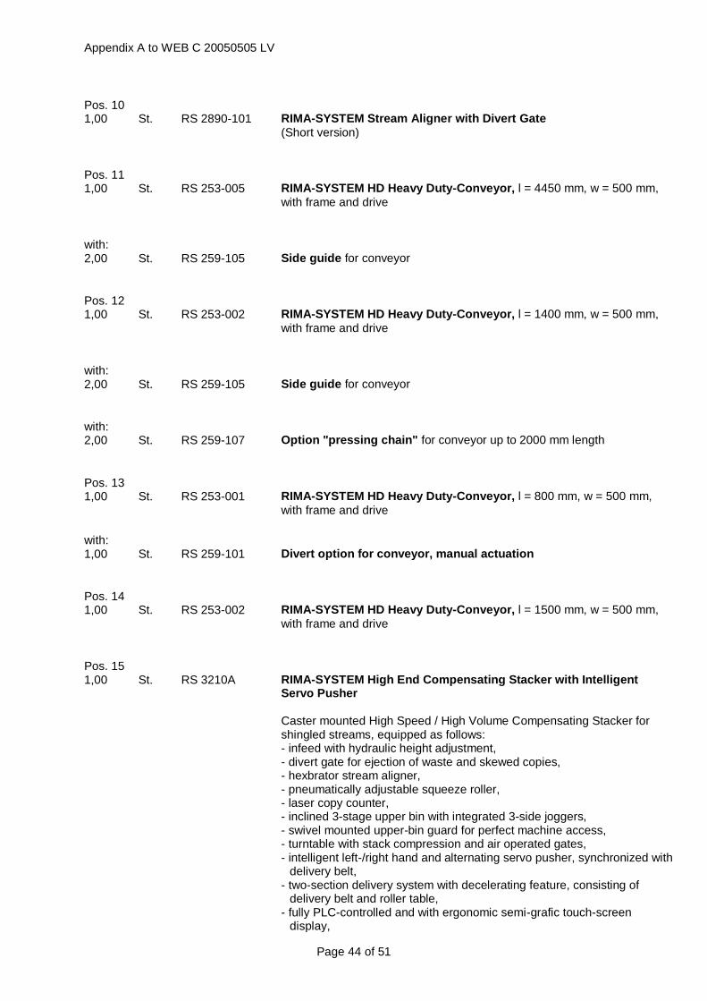
Appendix A to WEB C 20050505 LV
Page 44 of 51
Pos. 10 1,00 St. RS 2890-101 RIMA-SYSTEM Stream Aligner with Divert Gate
(Short version)
Pos. 11 1,00 St. RS 253-005 RIMA-SYSTEM HD Heavy Duty-Conveyor, l = 4450 mm, w = 500 mm,
with frame and drive
with: 2,00 St. RS 259-105 Side guide for conveyor
Pos. 12 1,00 St. RS 253-002 RIMA-SYSTEM HD Heavy Duty-Conveyor, l = 1400 mm, w = 500 mm,
with frame and drive
with: 2,00 St. RS 259-105 Side guide for conveyor
with: 2,00 St. RS 259-107 Option "pressing chain" for conveyor up to 2000 mm length
Pos. 13 1,00 St. RS 253-001 RIMA-SYSTEM HD Heavy Duty-Conveyor, l = 800 mm, w = 500 mm,
with frame and drive
with: 1,00 St. RS 259-101 Divert option for conveyor, manual actuation
Pos. 14 1,00 St. RS 253-002 RIMA-SYSTEM HD Heavy Duty-Conveyor, l = 1500 mm, w = 500 mm,
with frame and drive
Pos. 15 1,00 St. RS 3210A RIMA-SYSTEM High End Compensating Stacker with Intelligent
Servo Pusher Caster mounted High Speed / High Volume Compensating Stacker for shingled streams, equipped as follows: - infeed with hydraulic height adjustment, - divert gate for ejection of waste and skewed copies, - hexbrator stream aligner, - pneumatically adjustable squeeze roller, - laser copy counter, - inclined 3-stage upper bin with integrated 3-side joggers, - swivel mounted upper-bin guard for perfect machine access, - turntable with stack compression and air operated gates, - intelligent left-/right hand and alternating servo pusher, synchronized with
delivery belt, - two-section delivery system with decelerating feature, consisting of
delivery belt and roller table, - fully PLC-controlled and with ergonomic semi-grafic touch-screen
display,

Appendix A to WEB C 20050505 LV
Page 45 of 51
- 5 (five) turntables to cover the whole format range Basic technical data: min max copy format: 100x145mm 320x500mm copy thickness: 4p (57gsm) 96p (57 gsm) upper bin height: 200mm stack height: 330mm mech. speed: > 100.000 cph (product permitting) Standard colour is light-grey (RAL 7035). Other colors upon request. According to specific production needs several options such as town-sort, double squeeze roller and anti-static kit a.o. can be added to the basic machine configuration. See specifications for detailed technical data.
Pos. 16 1,00 St. RS 263-001 RIMA-SYSTEM 90° Flowturn with outfeed support
w = 600 mm, r = 600 mm, with frame and drive
Pos. 17 1,00 St. RS 253-002 RIMA-SYSTEM HD Heavy Duty-Conveyor, l = 1500 mm, w = 500 mm,
with frame and drive
with: 1,00 St. RS 259-101 Divert option for conveyor, manual actuation
with: 1,00 St. RS 259-105 Side guide for conveyor
Pos. 18 1,00 St. RS 263-001 RIMA-SYSTEM 90° Flowturn with outfeed support
w = 600 mm, r = 600 mm, with frame and drive
Pos. 19 1,00 St. RS 253-001 RIMA-SYSTEM HD Heavy Duty-Conveyor, l = 800 mm, w = 500 mm,
with frame and drive
with: 1,00 St. RS 259-101 Divert option for conveyor, manual actuation
with: 1,00 St. RS 259-105 Side guide for conveyor
Pos. 20 1,00 St. RS 600 Horizontal Log Stacker for High Speed / High Volume Applications
The RS 600 produces logs with a length of 800 - 1200 mm (31.50" - 47.24"). The logs are compressed, secured with end boards and strapped.

Appendix A to WEB C 20050505 LV
Page 46 of 51
Configuration: infeed spiral to the right, to the left or straight, log delivery table to the right or to the left Head/foot: 100 mm - 340 mm (3.94" - 13.40") Spine: 180 mm - 500 mm (7.10" - 19.70") Product thickness: 4 - 132 pages, 57 g/m² (35 lbs), 4 mm (0.16") max.
thickness Product orientation: spine leading Operating speed: up to 120.000 cph (product permitting) cycle time ≥ 27 sec, length 800 mm (31.50"); cycle
time > 31 sec, length 1200 mm (47.24") Input power: 400 VAC, 3 Ph, N, PE, 50/60 Hz, 40 A, 28 kW Air requirement: 110 l/min 6 bar (87 psi) Standard color: RAL 7035 (light grey). Other colors upon request at
additional price. The Log Stacker includes the following modules: - heavy duty steel construction - infeed with divert gate for waste copies and back-up, stream aligner and
double squeeze rollers. Waste copy conveyors can be used to underpass the infeed
- infeed spiral conveyor to the right, to the left or straight - another stream aligner - deviation of products downwards to the horizontal log stacking area - easily accessible stacking area with continuous stacking technology - central and easily accessible end board magazine (appr. 40") - servo driven log compression and strapping unit with closed belt channel - strapping unit, easily removable - log delivery on motorized delivery table with 2 buffer places for logs - drives and PLC with swivel mounted operator panel Detailed technical data according to specification sheet. End boards and strapping belt must be according to technical specifications !
with: 1,00 St. RS 600-101 Spiral to the right, log delivery to the right
Pos. 21 1,00 St. RS 650-300 Hoist with pneumatic log clamp, incl. 90°/180° log turning
Pos. 22 1,00 St. RS 253-201 RIMA-SYSTEM HD Heavy Duty-Round belt conveyor, l = 1000 mm,
w = 500 mm, lateral adjustment in the in- or outfeed, with frame and drive, with steel plate guide 500 mm x 40 mm
Pos. 23 1,00 St. RS 253-002 RIMA-SYSTEM HD Heavy Duty-Conveyor, l = 1090 mm, w = 500 mm,
with frame and drive
Pos. 24 1,00 St. RS 251-201 RIMA-SYSTEM HD Heavy Duty-Round belt conveyor, l = 800 mm,
w = 400 mm, lateral adjustment at in- or outfeed, with frame and drive
Pos. 25 1,00 St. RS 2630 RIMA-SYSTEM Conveyor Spiral
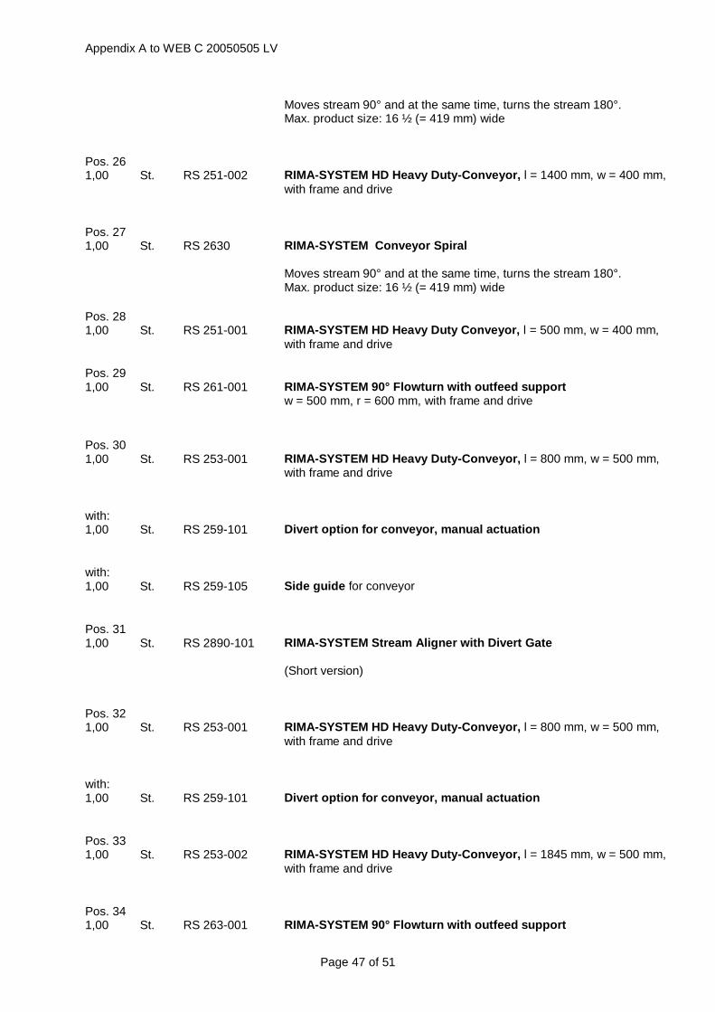
Appendix A to WEB C 20050505 LV
Page 47 of 51
Moves stream 90° and at the same time, turns the stream 180°. Max. product size: 16 ½ (= 419 mm) wide
Pos. 26 1,00 St. RS 251-002 RIMA-SYSTEM HD Heavy Duty-Conveyor, l = 1400 mm, w = 400 mm,
with frame and drive
Pos. 27 1,00 St. RS 2630 RIMA-SYSTEM Conveyor Spiral
Moves stream 90° and at the same time, turns the stream 180°. Max. product size: 16 ½ (= 419 mm) wide
Pos. 28 1,00 St. RS 251-001 RIMA-SYSTEM HD Heavy Duty Conveyor, l = 500 mm, w = 400 mm,
with frame and drive
Pos. 29 1,00 St. RS 261-001 RIMA-SYSTEM 90° Flowturn with outfeed support
w = 500 mm, r = 600 mm, with frame and drive
Pos. 30 1,00 St. RS 253-001 RIMA-SYSTEM HD Heavy Duty-Conveyor, l = 800 mm, w = 500 mm,
with frame and drive
with: 1,00 St. RS 259-101 Divert option for conveyor, manual actuation
with: 1,00 St. RS 259-105 Side guide for conveyor
Pos. 31 1,00 St. RS 2890-101 RIMA-SYSTEM Stream Aligner with Divert Gate
(Short version)
Pos. 32 1,00 St. RS 253-001 RIMA-SYSTEM HD Heavy Duty-Conveyor, l = 800 mm, w = 500 mm,
with frame and drive
with: 1,00 St. RS 259-101 Divert option for conveyor, manual actuation
Pos. 33 1,00 St. RS 253-002 RIMA-SYSTEM HD Heavy Duty-Conveyor, l = 1845 mm, w = 500 mm,
with frame and drive
Pos. 34 1,00 St. RS 263-001 RIMA-SYSTEM 90° Flowturn with outfeed support

Appendix A to WEB C 20050505 LV
Page 48 of 51
w = 600 mm, r = 600 mm, with frame and drive
Pos. 35 1,00 St. RS 253-002 RIMA-SYSTEM HD Heavy Duty-Conveyor, l = 1840 mm, w = 500 mm,
with frame and drive
Pos. 36 1,00 St. RS 253-001 RIMA-SYSTEM HD Heavy Duty-Conveyor, l = 800 mm, w = 500 mm,
with frame and drive
with: 1,00 St. RS 259-101 Divert option for conveyor, manual actuation
with: 1,00 St. RS 259-105 Side guide for conveyor
Pos. 37 1,00 St. RS 253-004 RIMA-SYSTEM HD Heavy Duty-Conveyor, l = 4000 mm, w = 500 mm,
with frame and drive
Pos. 38 1,00 St. RS 830 RIMA-SYSTEM "All-in-one"-Rotary Trimming line with three Knives
Compact trimming line (trimming unit, telescopic bumpturn, trimming unit) for head/foot and open side trimming. Two trimming units equipped as follows: Conveyor belts, infeed with stream aligner ("hexbrator"), upper and lower belts fixing the shingled stream during trimming. Height adjustable, independent trimming heads, each with upper and lower knife (two heads in first trimming unit, one in the second unit). Drives and control cabinet. Connections for exhaust system with failure detection and automatic machine stop. Width of untrimmed product: 113 mm (4,45") to 530 mm (20,87") before 1-side trim / 116 mm (4.57") to 530 mm (20.87") before 2-side trim Width of untrimmed product after: 110 mm (4.33") to 527 mm (20.75") after 1-side trim / 110 mm (4.33") to 524 mm (20.63") after 2-side trim
with: 1,00 St. RS 830-110 Option: Vacuum delivery belt for bumpturn RS 830
Vacuum assisted delivery belt instead of normal belt for the delivery conveyor of the bumpturn. Useful especially for high speed productions. Not available as upgrade. Must be ordered with the machine.
with: 1,00 St. RS 830-400 Option: Fourth knife for RS 830

Appendix A to WEB C 20050505 LV
Page 49 of 51
Additional height adjustable trimming head with upper and lower knife for RIMA-SYSTEM Eco Rotary Trimming Line with three knives allowing four side trimming. Not available as upgrade. Must be ordered with the machine.
Pos. 39 1,00 St. RS 230 RIMA-SYSTEM Multiformat Tower (combination of bumpturn and
flowturn) Height adjustable module mounted on one frame consisting of: ¤ Bumpturn for multiformat applications (from A5 to A3) with telescopic infeed conveyor, adjustable bump plate, delivery conveyor on upper level and ¤ 90° flowturn, w = 600 mm (24"), r = 600 mm (24") on lower level Includes drives and control cabinet.
with: 1,00 St. RS 220-110 Option: Vacuum assisted delivery belt
Automatic vacuum pump and perforated belt for perfect alignment of the shingled stream on the delivery conveyor of the bumpturn or tower. Especially for high speed applications. To use with RS 220 and RS 230. Not available as upgrade. Must be ordered with the machine.
Pos. 40 1,00 St. RS 253-001 RIMA-SYSTEM HD Heavy Duty-Conveyor, l = 600 mm, w = 500 mm,
with frame and drive
with: 1,00 St. RS 259-105 Side guide for conveyor
Pos. 41 1,00 St. RS 3210A RIMA-SYSTEM High End Compensating Stacker with Intelligent
Servo Pusher Caster mounted High Speed / High Volume Compensating Stacker for shingled streams, equipped as follows: - infeed with hydraulic height adjustment, - divert gate for ejection of waste and skewed copies, - hexbrator stream aligner, - pneumatically adjustable squeeze roller, - laser copy counter, - inclined 3-stage upper bin with integrated 3-side joggers, - swivel mounted upper-bin guard for perfect machine access, - turntable with stack compression and air operated gates, - intelligent left-/right hand and alternating servo pusher, synchronized with
delivery belt, - two-section delivery system with decelerating feature, consisting of
delivery belt and roller table, - fully PLC-controlled and with ergonomic semi-grafic touch-screen

Appendix A to WEB C 20050505 LV
Page 50 of 51
display, - 5 (five) turntables to cover the whole format range Basic technical data: min max copy format: 100x145mm 320x500mm copy thickness: 4p (57gsm) 96p (57 gsm) upper bin height: 200mm stack height: 330mm mech. speed: > 100.000 cph (product permitting) Standard colour is light-grey (RAL 7035). Other colors upon request. According to specific production needs several options such as town-sort, double squeeze roller and anti-static kit a.o. can be added to the basic machine configuration. See specifications for detailed technical data.
Pos. 42 1,00 St. RS 259-910 RIMA-SYSTEM Electrical Control Cabinet, wiring and installation
material (Basic Unit for one conveyor with drive)
with: 36,00 St. RS 259-911 Addition for RIMA-SYSTEM Electrical Control Cabinet, wiring and
installation material (Addition to Basic Unit for each additional conveyor with drive)
1,00 St. RS 259-901 Tachogenerator – signal from the press
0,00€ 0,00€
1,00 St. FARBE The whole equipment will be delivered in the colour light-grey
(similar to RAL 7035).
1,00 St. EL 3 - POWER SUPPLY, AIR CONNECTION, SUCTION SYSTEM -
The currents for power, the air connections to each machine as well as the suction system have to be provided by the customer.
1,00 St. I, S, T Installation, Start-up and training takes approx. 50 working days with one technician.

Appendix A to WEB C 20050505 LV
Page 51 of 51
Speed graph for RIMA-SYSTEM Compensating Stacker RS3210A