onboard processing satellite network architecture and … · 2013-08-30 · satellite network...
TRANSCRIPT
Con?ractor Repsrt Number: C R i sn8! 6
ONBOARD PROCESSING
SATELLITE NETWORK ARCHITECTURE
AND
CONTROL STUDY
EXECUTIVE SUMP-JARY NASA CONTRACT NAS3-24886
JUNE '987
S. JOSEPH CAMPANELLA
BENJAMIN A. PONTANO
AND
HARVEY Ci-iAirvlERS
COMSAT LABORATORIES
CLARKSBURG, MARYLAND
https://ntrs.nasa.gov/search.jsp?R=19870018277 2018-07-14T22:06:29+00:00Z

ABSTRACT FINAL REPORT
ONWARD PROCESSING SATELLITE NETWORK ARCHITECTURE AND CONTROL STUDY
CONTRACT NAS3-24886
S. JOSEPH CAMPANELIA BENJAMIN PONTANO HARVEY CHALMERS
COMSAT LABORATORIES CLARKSBURG, MARYIAND
For satellites to remain a vital part of future national and international communications, new system concepts that use their inherent advantages to the fullest must be created. This study is devoted to exploring new network architectures that talce maximum advantage of satellites equipped with onboard processing.
New satellite generations must accommodate various services for which satellites constitute the preferred vehicle of delivery. Such services tend to be those that are widely dispersed and present thin to medium loads to the system. Typical services considered are thin and medium route telephony, maritime, land and aeronautical radio, VS AT data, low bit rate video teleconferencing and high bit rate broadcast of high definition video. The study considers delivery of services by TDMA and FDMA multiplexing techniques and combinations of the two for individual and mixed service types. Onboard processing is an essential’part of the system architecture as it applies to the switching to rearrange the uplink signals into the downlink signals and serving hopping pencil beams. The possibilities offered by onboard circuit switched and packet switched architectures are examined and the results strongly support a preference for the latter. The memory used in the switch is designed to minimize its size by using advantageously the storage of signals in the space immediately in front of the antenna. A detailed design architecture encompassing the onboard packet switch and its control, the related demand assigned TDMA burst structures, and destination packet protocols for routing traffic are presented. Important features such as distributed network control, acquisition and synchronization, demand assignment, and advantageous use of voice and data activity to achieve channel multiplication are considered. Fundamental onboard hardware requirements comprising speed, memory size, chip count, and power are estimated. The study concludes with identification of key enabling technologies and identifies a plan to develop a POC model.

NAS3-24886 ONBOARD PROCESSING SATELLITE NETWORK
ARCHITECTURE AND CONTROL STUDY EXECUTIVE SUMMARY
1. INTRODUCTION
Satellites, as a consequence of the forces of the market place over more than two decades of application have been applied to a variety of services incorporating a variety of transmission means. Figure 1 illustrates the generic services delivered by satellite systems. These are fixed satellite services (FSS) including trunk telephony, broadcast TV and cable TV; mobile services including maritime (MMSS); land mobile (LMSS), aeronautical mobile satellite (AMSS) and intersatellite link (ISL). Transmission methods have evolved from analog FDMA used dominantly in the early years to digital FDMA and TDMA for voice and data. This process will accelerate as the world's public and private communications networks migrate to digital transmission. In the next twenty years concepts such as the integrated services digital network will take over completely.
Any new generation of satellites incorporating on board processing payloads and the associated network architecture should be capable of accommodating all or a subset of these digital services on a single satellite. This must be accomplished at low cost per unit of service delivered if satellites are to meet the competition from terrestrial transmission media, in particular high capacity, low cost lightguides operating at digital transmission rates per individual fiber potentially approaching a Gigabit per second. Such cost reduction must be a centerpiece of new designs and must consider the balance of cost between the space segment and the earth segment.
1.1 NETWORKS AND SERVICES
On board processing comprises a number of features that extend the network and service capabilities of a satellite beyond those of the traditional bent pipe satellite. For the purpose of this study, on board processing comprises the following:
1) Onboard demultiplexing and demodulation (also decoding as appropriate) of individual uplink carriers, operating as either digital frequency division multiple access (FDMA) or time division multiple access (TDMA) or a combination of both such as multiple frequency TDMA
1.1
NAS3-24886
(MF/TDMA). Implementation of such demultiplexing and demodulation is the subject of another contract NAS3-24885. Digital FDMA is necessarily a continuous transmission mode that can be used only with fixed beams, whereas TDMA and MF/TDMA are burst mode transmission modes that can operate in hopping beams.
2) Rerouting individual channels contained in the uplink transmissions emanating from a multiplicity of earth stations carried in multiple regional and spot beams into different channels of downlink transmissions.
3) Remodulation of the rearranged channels onto downlink carriers in the multiple regional and spot beams operating with either TDMA of MF/TDMA for hopping beams or FDMA or TDMA for fixed beams.
ADVANTAGE OF MULTIPLE SPOT BEAMS
The most economical satellite system results when the space segment is enhanced to provide high e.i.r.p. and gain to noise temperature (G/T) ratios enabling the earth segment to use small, low power stations to deliver the service. This leads to a space segment that has large aperture antennas and consequently narrow spot beams. However, the narrow spot beams reduce the coverage area of any one beam requiring either that many such spot beams be used simultaneously or that a few beams hop to various regions and dwell in each long enough to accommodate the traffic. The spot beams can be fixed if the region they cover carries sufficient traffic to fill the beam. This is suitable for regions that encompass areas of high population density. However, in regions where the density is sparse the beam must hop about to accumulate sufficient traffic to fill it. Typical multiple spot beam coverage of the countries of the Atlantic basin is illustrated in Figure 2.
INTERCONNECTIVITY USING A MICROWAVE SWITCH MATRIX
In a multibeam system, each earth station will establish circuits to several correspondent earth stations via the satellite. One way to accomplish this would be to establish a specific route between appropriate up and down beams to carry transmission bursts from the originating up beam to the destination down beam using a microwave switch matrix connected for an epoch sufficient to carry the transmission bursts between the stations in the respective up and down beams. For a
1.2
NAS3-24886
beam dwell zones, this would the microwave switch matrix an upbeam to a downbeam to
hopping beam network containing N hopping require the division of the time frame of into N(N-1) switch intervals, each connecting I
support one circuit between all stations. The onboard switch time frame is the same as the TDMA time frame. For large values of N, the number of switching intervals would become impractically large resulting in an impossibly cumbersome system. Also the stations would have to transmit short duration bursts each carrying a small number of channels which is inherently inefficient.
INTERCONNECTIVITY USING ONBOARD CIRCUIT SWITCH
A far better way to accomplish the connectivity is to permit each station to transmit and receive all of its traffic once each switch frame. This inherently limits the number of beam switchings to N on both the up and down beams and results in much longer and consequently higher efficiency burst transmissions. Implementing a system of this nature necessarily requires a switch with memory on board the satellite. The memory is needed to store the uplink channels to permit the onboard switch is arrange for their transmission on the downlinks. The minimum size of this memory is a capacity equal to that needed to store all channels of the system for one period of the onboard switching frame. This is actually accomplished by the design chosen.
Hopping spot beams with onboard switching constitutes the most advanced new concept for the next generation of satellites and its application will take place when it is demonstrated to be practical and economical. The ACTS is a hopping beam system incorporating most of the concepts that are needed to realize a satellite system of the type described above. For this reason, the ACTS architecture was reviewed from the point of view improving its performance. One avenue of possible improvement is to transfer some of the network control functions from the ACTS master control center located on the ground to the onboard processor. This might reduce the amount of information transmitted to the satellite to control the onboard switch. that the savings were small and likely implementation complexity.
Next the basic architecture of the the point of view of achieving improved fill efficiency. The input and output of the
However, an analysis showed not worth the added onboard
ACTS switch was studied from networking flexibility and frame ACTS switch are connected to
1.3

NAS3-24886
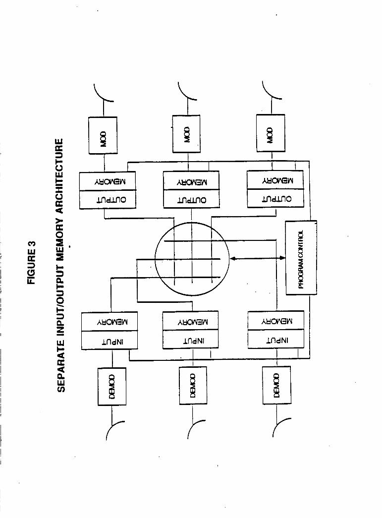
several hopping up and down beams that are synchronized in direction and time to receive and transmit traffic bursts. The switch uses a time-space-time circuit switch scheme, shown in Figure 3, comprising a pair of input memory banks which alternate their function in a ping-pong manner operating in conjunction with a space switch followed by a pair of output ping-pong memory banks to establish fixed channels through the satellite that connect a specific uplink time slot (channel) to a specific downlink time slot (channel). Each channel connection remains fixed until the connection is reassigned to setup another call. This is equivalent to the classical circuit switched operation used in telephone switching centers.
In this study a totally new concept is introduced that is much more flexible and considerably more efficient from the point of view of the channel capacity handled for the satellite payload. This concept is described briefly below and to a much greater extent in the text of the final report.
INTERCONNECTIVITY USING ONBOARD PACKET SWITCH
An onboard packet switch architecture is introduced that possesses all of the desirable properties of the onboard circuit switch pertaining to multiple beam hopping operation and adds a number of advantages compared to the circuit switch architecture. These additional advantages are:
1) Elimination of ground control of the switch from a master control center. All control of the onboard packet switch is obtained from unique destination addressing message sent as part of the burst preamble prior to the message data that assigns packet routing on demand through the onboard switch. No other command link is needed to control routing. Packet routing is described below. The satellite essentially operates autonomously establishing routes between up and down beams and reassigning the capacity of the network by generating the burst time plans for the stations of the network. Ground based override can be created by requiring the satellite to clear its burst time plans with a ground network control center but this would slow the response to demand.
2) Use of a packet structure for channels automatically results in voice and data activity compression and attending channel multiplication advantages. Channel capacity is used only when the message is actually present and is turned over to someone else who can use it when the
1.4

NAS3-24886
message ceases. For speech this can create a channel multiplication advantage of over 2:l for composite traffic loads of as few as 30 channels per station. For packet data the multiplication advantage can be much greater compared to that possible with circuit switched operation.
3) Use of the destination directed packet switched structure permits voice and data to be accommodated in the same way with the same protocols. Considering the rapid evolution of the merger of communications and computers in national and international networks and their mutual dependence on one another, this is an extremely important advantage of the packet switch architecture.
4) The packet switch can be implemented with only one memory using an "in-place" design described in the final report. Functioning of this "in place" switch architecture is illustrated in Figure 4. In-place operation refers to the process of inputting the newest arrival packet into the location just vacated by the most recent departing packet. It uses a dynamic switch control system that continuously updates the memory locations and requires high speed operation. To accomplish this, the destination address information must be sent at least one frame ahead of the packet to be switched. This causes the space immediately in the front of the antenna to act as a storage medium of one frame of the channel data eliminating the need to provide this element of the storage onboard and reduces the amount of onboard memory by a factor of 4:l compared to a circuit switch design using the ping-pong input and output memory. In the new packet switch design introduced here, this savings is traded for improved frame efficiency needed to accommodate increased overhead in the form of packet headers needed on each channel transmission by increasing the frame period to 8 or 16 ms. This also improves the overall TDMA frame efficiency which is determined by requirements for reference bursts, guard times and burst preambles which carry acquisition and synchronization, control and orderwire information.
PACKET ROUTING THROUGH THE ONBOARD SWITCH
The burst structures for packet routing at the earth stations and the satellite are shown in Figure 5. Each packet contains a header that identifies unique station identification numbers and port numbers. The composite of the two requires 16 uncoded bits which with rate 1/2 coding become 32 transmitted bits to identify 65,536 station/port combinations throughout the system. The header of a packet at an originating station contains the destination station's ID and originating port number. Onboard
1.5

NAS3-24886
the satellite the destination station's ID replaces the originating station's ID but the originating port number remains the same. The onboard switch assigns the packet to a traffic burst designated for the destination station. When received, if the destination station does not recognize the originating station's packet, it assumes 'the packet is a "call set up" packet and proceeds to assign an available port to the call. If it recognizes the packet ( recognition constitutes identification of the originating station's ID and port number as corresponding to a call that has already been setup and is still in progress ), it assigns it to the appropriate port. The procedure is the same for messages traveling in the reverse direction only with the designations "destination" and "originating" reversed. An alternative burst configuration that can be used when several packets are transmitted between the same originating and destination stations is shown in Figure 6. When several packets go to the same place it is not necessary to repeat the destination address for each. Rather, the packets are grouped according to destination and the destination address is given once along with the number of packets going to that address. This procedure reduces the capacity devoted to addressing and consequently improves the packet burst efficiency.
FRAME PERIOD FOR TDMA BEAM HOPPING OPERATION
The frame period for operating the system is considerably longer than that currently used for the ACTS. This is necessary to achieve high packet burst efficiency which is given by the ratio of the number of symbols contained in the traffic portion of the packet to the symbols in the sum of the packet header and the traffic portion. Long frame periods are obviously preferable because they increase the ratio of traffic information (which is the payload) to the information space lost to the header (which is the overhead). This same statement applies to the information space lost to the control field for distribution of reference bursts, and traffic burst preambles and guard time. A sample design case is considered in the report with the following parameters:
Burst rate of 120 Mbit/s
256 traffic bursts in the frame
An average of 5 packets per destination
Frame periods of 8 and 16 ms.
1.6

NAS3-24886
The overall frame efficiency, taking into account all of the losses mentioned above, is 89.6% and 94.6% for frame periods of 8 and 16 ms respectively.
Since the frame period for the sample design case is significantly longer than for ACTS, it might be thought that the memory size would be proportionately larger. This is not the case. Because the new packet switch design needs to store only one frame of traffic compared to four for the ACTS and the voice and data activity produces a 2:l or greater channel multiplication, the memory size needed to serve a given level of traffic is the same as for the ACTS when an 8 ms frame period is used and twice that of ACTS if a 16 ms frame period is used. Considering that onboard memory is increasing in density and speed as the result of technology enhancements, it is reasonable to expect that memory size and speed will not be limiting factors in the design of satellites to be flown in the 1995 to 2005 epoch. To serve 65,000 channels in this epoch will require 163 CMOS chips consuming 121 watts using the technology expected for the- time.
INTEGRATION OF OTHER SERVICES
The services most likely to be integrated in a future satellite system are the mobile and telephony. Integration as used here means the cross strapping of each service into the other and does not refer simply to carrying different service packages on the- same satellite. The study includes cross strapping mobile communications links which operate using single channel per carrier between the earth terminals and the satellite in fixed wide area coverage beams with telephony links in the public switched telephone network (PSTN) using beam hopping TDMA between the earth terminals and the satellite. The mobile links are assumed to operate using L band or UHF fixed beams. The onboard packet switch serves mobile terminals (MTs) and mobile service base stations (BTs) interfacing to the PSTN operating at L band. The onboard switch also interconnects mobile terminals to beam hopping TDMA K band FSS base stations which also interface to the PSTN. Thus calls can be originated in the PSTN to MTs and vice versa between users. The configuration can also support single hop MT to MT calls via the onboard switch.
The onboard processor inherently posses the property of interfacing with digital links arriving and departing on a number of beams. One or more of these beams can be intersatellite links. There will have to be a revision in the method of handling the packet header onboard so that the
1.7
NAS3-24886
switch will recognize when the destination of a packet is in the beam coverage of another satellite. Synchronization of the transmission over the intersatellite link will require a delay buffer in each direction of sufficient capacity to absorb the path length variation between satellites.
TECHNOLOGY C " G E S
Realization of a system of the nature identified in hinges on solving a number of system and technical prob discussed in the following.
the final report ems. These are
SYSTEM ARCHITECTURE DEVELOPMENT
The principal system problem is development of the detailed features of the destination directed packet architecture to be used on the links. This development must consider the following as a minimum:
1) Development of onboard program control software needed for operating the addressing structure of the "in-place" switch to accept and route each packet.
2) Development of a traffic burst management algorithm that will dynamically yield system wide traffic burst time plans and associated beam hopping time plans in response to the traffic demand.
3) Development of earth terminal interface protocols to respond to the satellite's traffic burst management messages.
4) Development of terrestrial PSTN signaling interface for normal signalling protocols such as CCITT signalling systems 5, 6,and 7 and North American CCIS.
5) Study of terrestrial interface requirements for accommodating the Fast Packet switching systems that are under consideration for future ISDN application.
6) Development of intersatellite link interface requirements needed to accommodate the packet switching concept.
7) Development of the traffic burst acquisition and synchronization protocol with emphasis on minimizing or eliminating the burst preamble.
1.8

NAS3-24886
KEY DEVICE DEVELOPMENT
The onboard hardware needed for implementing the destination directed onboard packet system will require the availability of several key devices. Guided development of these key devices by NASA can accelerate their availability and thus enhance the feasibility of implementing such an approach in the 1990's.
a) CUSTOM LOGIC DEVICES
Two categories of custom logic devices that require development to provide low power implementation of the "in-place" switch architecture are:
1) ECL,CMOS, or GaAs logic arrays having a density of 5000 gates and operating at a 120 MHz clock rate. This is probably within today's ECL technology. However, future GaAs or CMOS technology is desirable for reduced power ( 100 pWatt per gate).
2) GaAs logic arrays having densities ranging from 500 to 10000 gates, operating at a1200 MHz clock rate and exhibiting 100 pWatt per gate.
b) MEMORY RAMs
Memory will require advanced RAM technology. Static RAMs having densities of at least 256K per chip are needed to keep chip count at a reasonable level. They should exhibit an access speed of 100 ns and should have the ability to withstand the radiation expected of a geostationary satellite. GaAs appears to offer the best potential for reaching this goal in the next decade.
POC TEST BED
Even though the realization of a flight qualified model of the packet switch needs to await the development of the hardware devices identified above, it is possible to implement most of the key functions needed to demonstrate the feasibility of the concept, test its performance and guide the development of the sophisticated protocols. This POC development would encompass: Architecture and Protocol Development, Hardware Design, Test Bed Implementation and Test and Evaluation. The program is anticipated to encompass approximately 18 months.
1.9

0 K

FIGURE 2 SPOT BEAM ANTENNA COVERAGE OF ATLANTIC OCEAN BASIN. COUNTRIES
W U 3
W tj
a
W c K U e W v)
a
I m

n UPUNK
I I
H
D I C I 88 A I 07 C7 07 A7 UInm
DOWNLINK
M A 7
FIGURE 4 ON BOARD DUAL PORT SWITCH OPERATION
I
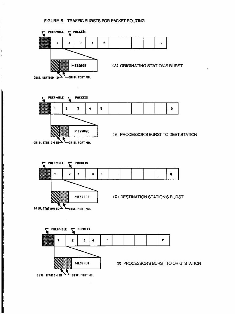
FIGURE 5. TRAFFIC BURSTS FOR PACKET ROUTING
( A ) ORIGINATING STATION'S BURST
OR16. STATION I D \L0R,6. PORT NO.
( B 1 PROCESSOR'S BURST TO DEST.STATION
OR16. STATION ISLDEST. PORT NO.
(C 1 DESTINATION STATION'S BURST
'F; c PACKETS
(D) PROCESSOR'S BURST TO ORIG. STATION
DEST. STATION IO^ +EST. PORT NO.
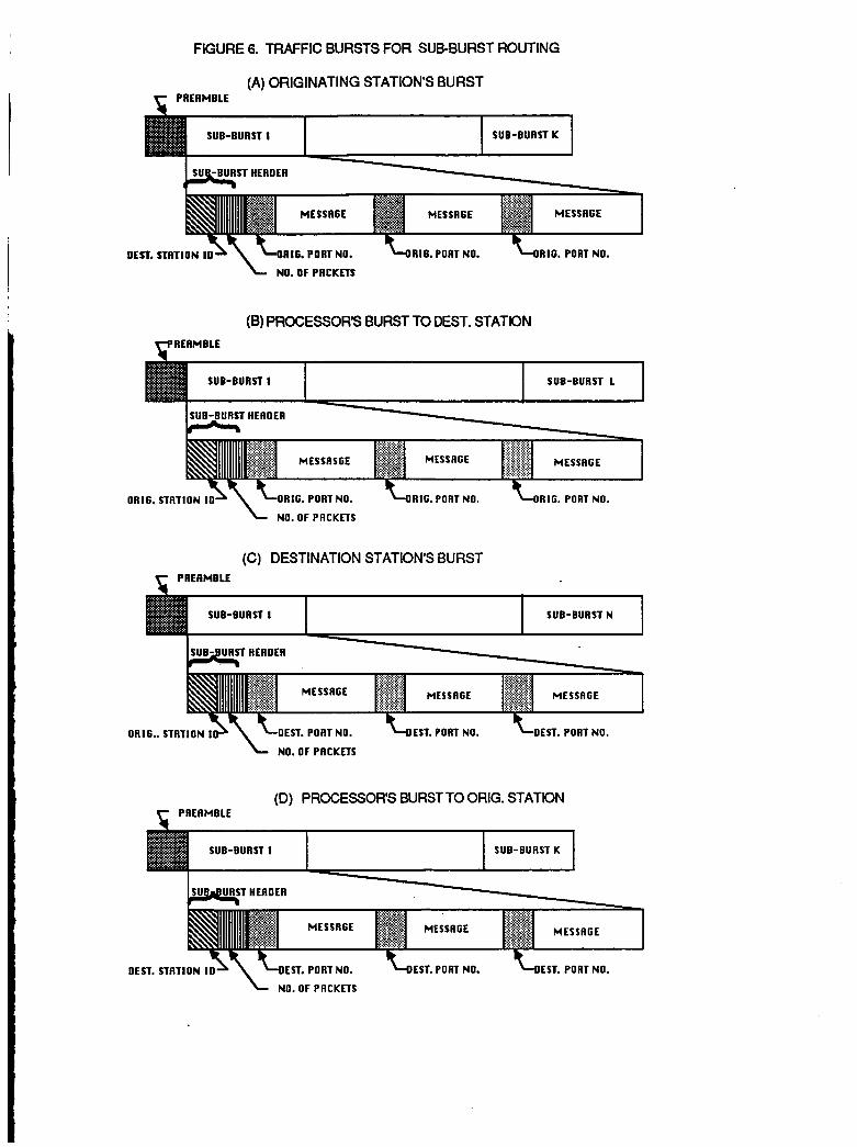
FIGURE 6. TRAFFIC BURSTS FOR SUBBURST ROUTING
(A) ORIGINATING STATION'S BURST
SUB-BURST 1 SUB-BURST K
(B) PROCESSORS BURST TO DEST. STATION
SUB-BURST I SUB-BURST 1
ORIG. STATION 1 0 1 &RIG. PORT NO. &RIG. PORT NO. -LORIG. PORT NO. NO. OF PRCKETS
(C) DESTINATION STATION'S BURST
SUB-BURST 1 SUB-BURST N
(D) PROCESSORS BURST TO ORIG. STATION
OEST. STATION I O OEST. PORT NO. OEST. PORT NO.
NO. OF PRCKETS
1. Report No.
CR180816
On-Board Processing S a t e l l i t e Network Architecture and Control Study
2. Government Accession No.
7. Author@)
S. Joseph Campanel 1 a B. Pontano H. Chalrners
9. Performing Organization Name and Address
COMSAT 22300 Comsat Drive C1 arksburg, MD 20871
12. Sponsoring Agency Name and Address
NASA-LEWIS Research Center 21000 Brookpark Road Cleveland, OH 44135
15. Supplementary Notes
3. Recipient's Catalog No.
5. Report Date
June 1987 6. Performing Organization Code
650-60-26 8. Performing Organization Report No
10. Work Unit No.
11. Contract or Grant No.
NAS3-24886 13. Type of Report and Period Covered
14. Sponsoring Agency Code
16. Abstract-
see attached
17. Key Words (Suggested by Author@)) IS. Distribution Statement
General Re1 ease
19. Security Classif. (of this report)
uncl ass i f i ed 20. Security Classif. (of this page) 21. No of pages 22. Price'
1 I I
*For sale by the National Technical Information Service, Springfield, Virginia 221 61 NASA FORM 1626 OCT 86