on undivided highways with two or more lanes in a … 07, 2012 · chapter 300 geometric cross...
TRANSCRIPT

HIGHWAY DESIGN MANUAL 300-1 July 24, 2009
CHAPTER 300 GEOMETRIC CROSS SECTION
Topic 301 - Traveled Way Standards
Index 301.1 - Traveled Way Width The traveled way width is determined by the number of lanes demanded by the design hourly volume. The traveled way width does not include curbs, dikes, gutters, or gutter pans. The basic lane width for new construction on two-lane and multilane highways, ramps, collector roads, and other appurtenant roadways shall be 12 feet. For roads with curve radii of 300 feet or less, widening due to offtracking should be considered. See Index 404.1 and Table 504.3A. For roads under other jurisdictions, see Topic 308.
301.2 Cross Slopes (1) General. The purpose of sloping on roadway
cross sections is to provide a mechanism to direct water (usually from precipitation) off the traveled way. Undesirable accumulations of water can lead to hydroplaning or other problems which can increase accident potential. See Topics 831 and 833 for hydroplaning considerations.
(2) Standards.
(a) The standard cross slope to be used for new construction on the traveled way for all types of surfaces shall be 2 percent.
(b) For resurfacing or widening when necessary to match existing cross slopes, the minimum shall be 1.5 percent and the maximum shall be 3 percent. However, the cross slope on 2-lane and multilane AC highways should be increased to 2 percent if the cost is reasonable.
(c) On unpaved roadway surfaces, including gravel and penetration treated earth, the cross slope shall be 2.5 percent to 5.0 percent.
On undivided highways with two or more lanes in a normal tangent section, the high point of the crown should be centered on the pavement and the pavement sloped toward the edges on a uniform grade.
For rehabilitation and widening projects, the maximum algebraic difference in cross slope between adjacent lanes of opposing traffic for either 2-lane or undivided multilane highways should be 6 percent.
On divided highway roadbeds, the high point of crown may be centered at, or left of, the center of the traveled way, and preferably over a lane line (tent sections). This strategy may be employed when adding lanes on the inside of divided highways, or when widening an existing "crowned" 2-lane highway to a 4-lane divided highway by utilizing the existing 2-lane pavement as one of the divided highway roadbeds.
For new construction, the maximum shall be 4 percent.
The maximum algebraic difference in cross slope between same direction traffic lanes of divided highway roadbeds should be 4 percent.
The maximum difference in cross slope between the traveled way and the shoulder should not exceed 8 percent. This applies to new construction as well as pavement overlay projects.
Topic 302 - Shoulder Standards
At freeway entrances and exits, the maximum difference in cross slope between adjacent lanes, or between lanes and gore areas, should not exceed 5 percent.
302.1 Width The shoulder widths given in Table 302.1 shall be the minimum continuous usable width of paved shoulder. For new construction, and major reconstruction projects on conventional highways, adequate width should be provided to permit shared use by motorists and bicyclists.
See Index 308.1 for shoulder width requirements on city streets or county roads. See shoulder definition, Index 62.1(8).
See Index 1102.2 for shoulder width requirements next to noise Barriers.
HDM PREVIO
US TO
CHANGE DATED 05
/07/12

300-2 HIGHWAY DESIGN MANUAL January 4, 2007
Table 302.1 Standards for Paved
Shoulder Width Paved Shoulder Width (ft) Left Right (8)
Freeways & Expressways
2 lanes (1) -- 8(6)
4 lanes (1) 5 10 6 or more lanes (1) 10 10 Auxiliary lanes -- 10 Freeway-to-freeway connections Single and two-lane connections 5 10 Three-lane connections 10 10 Single-lane ramps 4(2) 8 Multilane ramps 4(2) 8(3)
Multilane undivided -- 10 Collector-Distributor 5 10
Conventional Highways
Multilane divided 4-lanes 5 8 6-lanes or more 8 8 Urban areas with speeds less than or equal to 45 mph and
curbed medians
2(4)
8(7)
Multilane undivided -- 8(7)
2-lane RRR See Index 307.3 New construction See Table 307.2 Slow-moving vehicle lane -- 4(5)
Local Facilities
Frontage roads See Index 310.1 Local facilities crossing State facilities See Index 308.1 NOTES: (1) Total number of lanes in both directions including separate roadways (see Index 305.6). If a lane is added to
one side of a 4-lane facility (such as a truck climbing lane) then that side shall have 10 feet left and right shoulders. See Index 62.1.
(2) May be reduced to 2 feet. 4 feet preferred in urban areas and/or when ramp is metered. See Index 504.3. (3) In restrictive situations, may be reduced to 2 feet or 4 feet (preferred in urban areas) in the 2-lane section of a
non-metered ramp which transitions from a single lane. May be reduced to 2 feet in ramp sections having 3 or more lanes. See Index 504.3.
(4) For posted speeds less than or equal to 35 mph, shoulder may be omitted (see Index 303.5(5)) except where drainage flows toward the curbed median.
(5) On right side of climbing or passing lane section only. See Index 1003.2 if bike lanes are present. (6) 10-foot shoulders preferred. (7) Where parking is allowed, 10 feet to 12 feet shoulders preferred. (8) Shoulders adjacent to abutment walls, retaining walls in cut locations, and noise barriers shall be 10 feet wide.
HDM PREVIO
US TO
CHANGE DATED 05
/07/12

HIGHWAY DESIGN MANUAL 300-3 September 1, 2006 302.2 Cross Slopes (1) General - When a roadway crosses a bridge
structure, the shoulders shall be in the same plane as the adjacent traveled way.
(2) Left Shoulders - In depressed median sections, shoulders to the left of traffic shall be sloped at 2 percent away from the traveled way.
In paved median sections, shoulders to the left of traffic shall be designed in the plane of the traveled way. Maintenance paving beyond the edge of shoulder should be treated as appropriate for the site, but consideration needs to be given to the added runoff and the increased water depth on the pavement (see discussion in Index 831.4 (5) "Hydroplan-ing").
(3) Right Shoulders- In normal tangent sections, shoulders to the right of traffic shall be sloped at 2 percent to 5 percent away from the traveled way.
The above flexibility in the design of the right shoulder allows the designer the ability to conform to regional needs. Designers shall consider the following during shoulder cross slope design.
• In most areas a 5 percent right shoulder cross slope is desired to most expeditiously remove water from the pavement and to allow gutters to carry a maximum water volume between drainage inlets. The shoulders must have adequate drainage interception to control the "water spread" as discussed in Table 831.3 and Index 831.4. Conveyance of water from the total area transferring drainage and rainwater across each lane and the quantity of intercepting drainage shall also be a consideration in the selection of shoulder cross slope. Hydroplaning is discussed in Index 831.4 (5).
• In locations with snow removal operations it is desirable for right shoulders to slope away from traffic in the same plane as the traveled way. This design permits the snowplowing crew to remove snow from
the lanes and the shoulders with the least number of passes.
• If shoulders are Portland cement concrete and the District plans to convert shoulders into through lanes within the 20 years following construction, then shoulders are to be built in the plane of the traveled way and to lane standards for width and structural section. (See Index 603.4).
• If use of the highway by pedestrians is expected in areas where sidewalks are not to be constructed, new shoulder cross slope and drainage design should accommodate pedestrians and consideration should be given to pedestrian and bicycle needs on reconstruction of existing shoulders. This decision should involve the local agency and must be consistent with the design guidance provided in Topic 105 and in Design Information Bulletin 82, "Pedestrian Accessibility Guidelines for Highway Projects" for people with disabilities.
Shoulder slopes for superelevated curves are discussed in Index 202.2.
See Index 307.2 for shoulder slopes on 2-lane roads with 2-foot and 4-foot shoulders.
Topic 303 - Curbs, Dikes, and Side Gutters
303.1 General Policy Curb (including curb with gutter pan), dike, and side gutter all serve specific purposes in the design of the roadway cross section. Curb is primarily used for channelization, access control, separation between pedestrians and vehicles, and to enhance delineation. Dike is specifically intended for drainage and erosion control where stormwater runoff cannot be cost effectively conveyed beyond the pavement by other means. Curb with gutter pan serves the purpose of both curb and dike. Side gutter is intended to prevent runoff from a cut slope on the high side of a superelevated roadway from running across the pavement and is discussed further in Index 834.3.
HDM PREVIO
US TO
CHANGE DATED 05
/07/12

300-4 HIGHWAY DESIGN MANUAL September 1, 2006 Aside from their positive aspects in performing certain functions, curbs and dikes can have undesirable effects. In general, curbs and dikes should present the least potential obstruction, yet perform their intended function. As operating speeds increase, lower curb and dike height is desirable. Curbs and dikes are not considered traffic barriers.
On urban and suburban conventional highways where right of way is costly and/or difficult to acquire, it is appropriate to consider the use of a “closed” highway cross section with curb, or curb with gutter pan. There are also some situations where curb is appropriate in freeway settings. The following criteria describe typical situations where curb or curb with gutter pan may be appropriate:
(a) Where needed for channelization, delineation, or other means of improving traffic flow and safety.
(b) At ramp connections with local streets for the delineation of pedestrians walkways and continuity of construction at a local facility.
(c) As a replacement of existing curb with gutter pan and sidewalk.
(d) On frontage roads on the side adjacent to the freeway to deter vehicular damage to the freeway fence.
(e) When appropriate to conform to local arterial street standards.
(f) Where it may be necessary to solve or mitigate operational deficiencies through control or restriction of access of traffic movements to abutting properties or traveled ways.
(g) In freeway entrance ramp gore areas (at the inlet nose) when the gore cross slope exceeds standards.
(h) At separation islands between a freeway and a collector-distributor to provide a positive separation between mainline traffic and collector-distributor traffic.
(i) Where sidewalk is appropriate.
(j) As a tool for traffic calming where operating speeds are 40 miles per hour or less.
(k) To deter vehicular damage of traffic signal standards.
Dike is appropriate where controlling drainage is not feasible via sheet flow or where it is necessary to contain/direct runoff to interception devices. On cut slopes, dike also protects the toe of slope from erosion. Dike may also be necessary to protect adjacent areas from flooding.
303.2 Curb Types and Uses
The use of curb should be avoided on facilities with operating speeds greater than 45 miles per hour, except as noted in Table 303.1. For projects where the use of curb is appropriate, it should be the type shown in Table 303.1.
Depending on their intended function, one of two general classifications of curb design are selected as appropriate. The two general classifications are vertical and sloped. Vertical curbs are actually nearly vertical (approximate batter of 1:4) and vary in height from 6 inches to 8 inches. Sloped curbs (approximate batter of 2:3 or flatter) vary in height from 8 inches to 6 inches.
Sloped curbs are more easily mounted by motor vehicles than vertical curbs. Since curbs are not generally adequate to prevent a vehicle from leaving the roadway, a suitable traffic barrier should be provided where redirection of vehicles is needed. Where curb is placed to deter vehicles from intentionally entering the area behind the curb (e.g., truck offtracking), in most cases the curb will not prevent an errant vehicle from mounting the curb.
Curb with gutter pan may be provided to enhance the visibility of the curb and thus improve delineation. This is most effective where the adjacent pavement is a contrasting color or material. B2-4 and B4 curbs are appropriate for enhancing delineation. Where curb with gutter pan is intended as delineation and has no drainage function, the gutter pan should be in the same plane as the adjacent pavement.
HDM PREVIO
US TO
CHANGE DATED 05
/07/12
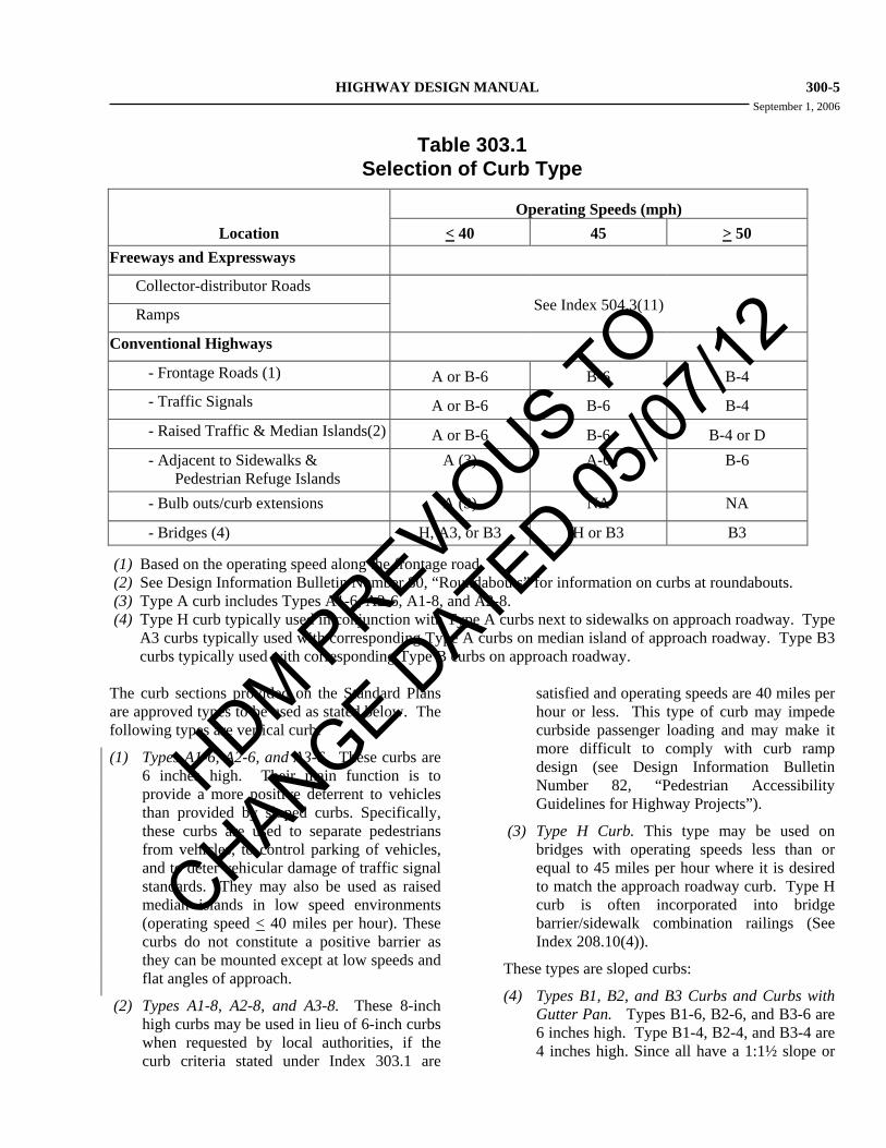
HIGHWAY DESIGN MANUAL 300-5 September 1, 2006
Table 303.1 Selection of Curb Type
Operating Speeds (mph)
Location < 40 45 > 50 Freeways and Expressways Collector-distributor Roads
See Index 504.3(11)
Ramps
Conventional Highways - Frontage Roads (1) A or B-6 B-6 B-4 - Traffic Signals A or B-6 B-6 B-4 - Raised Traffic & Median Islands(2) A or B-6 B-6 B-4 or D - Adjacent to Sidewalks &
Pedestrian Refuge Islands A (3) A-6 B-6
- Bulb outs/curb extensions A (3) NA NA - Bridges (4) H, A3, or B3 H or B3 B3
(1) Based on the operating speed along the frontage road. (2) See Design Information Bulletin Number 80, “Roundabouts” for information on curbs at roundabouts. (3) Type A curb includes Types A1-6, A2-6, A1-8, and A2-8. (4) Type H curb typically used in conjunction with Type A curbs next to sidewalks on approach roadway. Type
A3 curbs typically used with corresponding Type A curbs on median island of approach roadway. Type B3 curbs typically used with corresponding Type B curbs on approach roadway.
The curb sections provided on the Standard Plans are approved types to be used as stated below. The following types are vertical curb:
(1) Types A1-6, A2-6, and A3-6. These curbs are 6 inches high. Their main function is to provide a more positive deterrent to vehicles than provided by sloped curbs. Specifically, these curbs are used to separate pedestrians from vehicles, to control parking of vehicles, and to deter vehicular damage of traffic signal standards. They may also be used as raised median islands in low speed environments (operating speed < 40 miles per hour). These curbs do not constitute a positive barrier as they can be mounted except at low speeds and flat angles of approach.
(2) Types A1-8, A2-8, and A3-8. These 8-inch high curbs may be used in lieu of 6-inch curbs when requested by local authorities, if the curb criteria stated under Index 303.1 are
satisfied and operating speeds are 40 miles per hour or less. This type of curb may impede curbside passenger loading and may make it more difficult to comply with curb ramp design (see Design Information Bulletin Number 82, “Pedestrian Accessibility Guidelines for Highway Projects”).
(3) Type H Curb. This type may be used on bridges with operating speeds less than or equal to 45 miles per hour where it is desired to match the approach roadway curb. Type H curb is often incorporated into bridge barrier/sidewalk combination railings (See Index 208.10(4)).
These types are sloped curbs:
(4) Types B1, B2, and B3 Curbs and Curbs with Gutter Pan. Types B1-6, B2-6, and B3-6 are 6 inches high. Type B1-4, B2-4, and B3-4 are 4 inches high. Since all have a 1:1½ slope or
HDM PREVIO
US TO
CHANGE DATED 05
/07/12

300-6 HIGHWAY DESIGN MANUAL September 1, 2006 flatter on the face, they are mounted more
easily than Type A curbs. Typical uses of these curbs are for channelization including raised median islands. B2 curb with gutter pan also serves as drainage control.
(5) Type B4 Curb. Type B4 curb with gutter pan is 3 inches high and is typically used on ramp gores as described in Index 504.3(11). It may also be appropriate where a lower curb is desirable.
(6) Type D Curb. Type D curb is 4 inches or 6 inches high and is typically used for raised traffic islands, collector-distributor separation islands, or raised medians when operating speeds equal or exceed 50 miles per hour.
(7) Type E Curb. This essentially is a rolled gutter used only in special drainage situations.
Curbs with gutter pans, along with the shoulder, may provide the principal drainage system for the roadway. Inlets are provided in the gutter pan or curb, or both.
Gutter pans are typically 2 feet wide but may be 1 foot to 4 feet in width, with a cross slope of typically 8.33 percent to increase the hydraulic capacity. Gutter pan cross slopes often need to be modified at curb ramps in order to meet accessibility requirements. See Design Information Bulletin Number 82, “Pedestrian Accessibility Guidelines for Highway Projects” for accessibility standards. Warping of the gutter pan should be limited to the portion within 2 feet to 3 feet of the gutter flow line to minimize adverse driving effects.
Curbs and gutter pans are cross section elements considered entirely outside the traveled way, see Index 301.1.
Where bicycles are permitted and the shoulder width is 4 feet, gutter pan width should be reduced to 1 foot, so 3 feet is provided between the traffic lane and the longitudinal joint at the gutter pan. For mandatory requirements regarding drainage inlet grates for bicycles, see Index 1003.6(3).
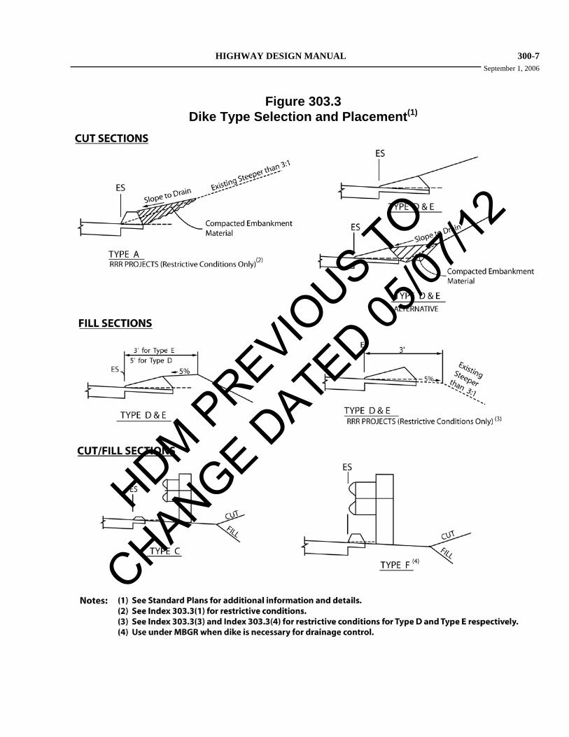
303.3 Dike Types and Uses Use of dike is intended for drainage control and should not be used in place of curb. Dikes placed
adjoining the shoulder, as shown in Figures 307.2, 307.4, and 307.5, provide a paved triangular gutter within the shoulder area. The dike sections provided on the Standard Plans are approved types to be used as stated below. Dikes should be selected as illustrated in Figure 303.3.
(1) Type A Dike. The use of Type A dike should be avoided. For RRR projects, Type A dike may be used in cut sections with slopes steeper than 3:1 and where existing conditions do not allow for construction of the wider Type D or E dikes. Compacted embankment material should be placed behind the back of dike as shown in Figure 303.3.
Dikes should be designed so that roadway runoff is contained within the limits specified in Index 831.3. For most situations Type E dike is the preferred dike type as discussed below.
(2) Type C Dike. This low dike, 2 inches in height, may be used to confine small concentrations of runoff. The capacity of the shoulder gutter formed by this dike is small. Due to this limited capacity, the need for installing an inlet immediately upstream of the beginning of this dike type should be evaluated. This low dike can be traversed by a vehicle and allows the area beyond the surfaced shoulder to be used as an emergency recovery and parking area. The Type C dike is the only dike that may be used in front of guardrail. In such cases, it is not necessary to place compacted embankment material behind Type C dike.
(3) Type D Dike. This 6-inch high dike provides about the same capacity as the Type A dike but has the same shape as the Type E dike. The quantity of material in the Type D dike is more than twice that of a Type E dike. It should only be used where there is a need to contain higher volumes of drainage. Compacted embankment material should be placed behind the back of dike as shown in Figure 303.3. For RRR projects that do not widen pavement, compacted embankment material may be omitted on existing fill slopes steeper than 3:1 when there is insufficient room to place the embankment material.
HDM PREVIO
US TO
CHANGE DATED 05
/07/12
HIGHWAY DESIGN MANUAL 300-7 September 1, 2006
Figure 303.3 Dike Type Selection and Placement(1)
HDM PREVIO
US TO
CHANGE DATED 05
/07/12

300-8 HIGHWAY DESIGN MANUAL September 1, 2006 (4) Type E Dike. This 4-inch high dike provides
more capacity than the Type C dike. Because Type E dike is easier to construct than Type D dike, and has greater drainage capacity than Type C dike, it is the preferred dike type for most installations. Compacted embankment material should be placed behind the back of dike as shown in Figure 303.3. For RRR projects that do not widen pavement, compacted embankment material may be omitted on existing fill slopes steeper than 3:1 where there is insufficient room to place the embankment material.
(5) Type F Dike. This 4-inch high dike is to be used where dike is necessary for drainage underneath a guardrail installation. This dike is placed directly under the face of metal beam guardrail installations.
303.4 Side Gutters For information on side gutters, see Index 834.3.
303.5 Position of Curbs and Dikes Curbs located at the edge of the traveled way may have some effect on lateral position and speed of moving vehicles, depending on the curb configuration and appearance. Curbs with low, sloped faces may encourage drivers to operate relatively close to them. Curbs with vertical faces may encourage drivers to slow down and/or shy away from them and, therefore, it may be desirable to incorporate some additional roadway width.
All dimensions to curbs (i.e., offsets) are from the near edge of traveled way to bottom face of curb. All dimensions to dikes are from the near edge of traveled way to flow line. Curb and dike offsets should be in accordance with the following:
(1) Through Lanes. The offset from the edge of traveled way to the face of curb or dike flow line should be no less than the shoulder width, as set forth in Table 302.1.
(2) Channelization. Island curbs used to channelize intersection traffic movements should be positioned as described in Index 405.4.
(3) Separate Turning Lanes. Curb offsets to the right of right-turn lanes in urban areas may be
reduced to 2 feet if design exception approval for nonstandard shoulder width has been obtained in accordance with Index 82.2. No curb offset is required to the left of left-turn lanes in urban areas unless there is a gutter pan.
(4) Median Openings. Median openings (Figure 405.5) should not be separated with curb unless necessary to delineate areas occupied by traffic signal standards.
(5) Urban Conventional Highways. When the posted speed is less than or equal to 35 miles per hour, no median curb offset is required if there is no gutter pan.
(6) Structure Approach Slabs. When a dike is required to protect the side slope from erosion, it should be placed on the structure approach and sleeper slabs as well as aligned to tie into the end of the structure railing. The guardrail alignment and edge of shoulder govern the positioning of the dike.
When the Type 14 structure approach slab is used, concrete dikes are preferred. Hot mixed asphalt dike will inevitably crack due to expansion and contraction at the approach/sleeper slab joint. A metal dike insert is used to carry the flow across the sealed joint. The insert acts as a water barrier to minimize erosion of the fill slope. Details of the metal dike insert are shown in the structure approach plans provided by the Division of Engineering Services, (DES).
(7) Bridges and Grade Separation Structures. When both roadbeds of a curbed divided highway are carried across a single structure, the median curbs on the structure should be in the same location as on adjacent roadways.
(8) Approach Nose. The approach nose of islands should also be designed utilizing a parabolic flare, as discussed in Index 405.4.
303.6 Curbs and Dikes on Frontage Roads and Streets Continuous curbs or dikes are not necessarily required on all frontage roads. Where curbs or dikes are necessary for drainage control or other reasons, they should be consistent with the
HDM PREVIO
US TO
CHANGE DATED 05
/07/12
HIGHWAY DESIGN MANUAL 300-9 September 1, 2006 guidelines established in this topic and placed as shown on Figure 307.4. Local curb standards should be used when requested by local authorities for roads and streets that will be relinquished to them.
Topic 304 - Side Slopes
304.1 Side Slope Standards Slopes should be designed as flat as is reasonable. For new construction, widening, or where slopes are otherwise being modified, embankment (fill) slopes should be 4:1 or flatter.
(a) Safety. Flatter slopes provide better recovery for errant vehicles that may run off the road. A cross slope of 6:1 or flatter is suggested for high speed roadways whenever it is achievable. Cross slopes of 10:1 are desirable.
Factors affecting slope design are as follows:
Recoverable slopes are embankment slopes 4:1 or flatter. Motorists who encroach on recoverable slopes can generally stop their vehicles or slow them enough to return to the traveled way safely.
A slope which is between 3:1 and 4:1 is considered traversable, but not recoverable. Since a high percentage of vehicles will reach the toe of these slopes, the recovery area should be extended beyond the toe of slope. The AASHTO Roadside Design Guide should be consulted for methods of determining the preferred extent of the runout area.
Embankment slopes steeper than 3:1 are considered non-recoverable and non-traversable. District Traffic, and the AASHTO Roadside Design Guide should be consulted for methods of determining the preferred treatment.
Regardless of slope steepness, it is desirable to round the top of slopes so an encroaching vehicle remains in contact with the ground. Likewise, the toe of slopes should be rounded to prevent vehicles from nosing into the ground.
(b) Erosion Control. Slope designs steeper than 4:1 must be approved by the District Landscape Architect in order to assure compliance with the regulations affecting Stormwater Pollution contained in the Federal Clean Water Act (see Index 82.4). Slope steepness and length are two of the most important factors affecting the erodability of a slope. Slopes should be designed as flat as possible to prevent erosion. However, since there are other factors such as soil type, climate, and exposure to the sun, District Landscape Architecture and the District Stormwater Coordinator must be contacted for erosion control requirements.
A Storm Water Data Report (SWDR) documents project information and considerations pertaining to Storm Water Best Management Practices (BMPs) and Erosion Control methods. The SWDR is prepared and signed by key personnel (including the District Landscape Architect) at the completion of each phase of a project. By signing the SWDR, the District Landscape Architect approves compliance with the proposed slope designs.
(c) Structural Integrity. Slopes steeper than 2:1 require approval of District Maintenance. The Geotechnical Design Report (See Topic 113) will recommend a minimum slope required to prevent slope failure due to soil cohesiveness, loading, slip planes and other global stability type failures. There are other important issues found in the Geotechnical Design Report affecting slope design such as the consistency of the soil likely to be exposed in cuts, identification of the presence of ground water, and recommendations for rock fall.
(d) Economics. Economic factors such as purchasing right of way, imported borrow, and environmental impacts frequently play a role in the decision of slope length and steepness. In some cases, the cost of stabilizing, planting, and maintaining steep slopes may exceed the cost of
HDM PREVIO
US TO
CHANGE DATED 05
/07/12
300-10 HIGHWAY DESIGN MANUAL September 1, 2006
additional grading and right of way to provide a flatter slope.
(e) Aesthetics. Flat, gentle, and smooth, well transitioned slopes are visually more satisfying than steep, obvious cuts and fills. In addition, flatter slopes are more easily revegetated, which helps visually integrate the transportation improvement within its surrounding environment. Contact the District Landscape Architect when preparing a contour grading plan.
In light grading where normal slopes catch in a distance less than 18 feet from the edge of the shoulder, a uniform catch point, at least 18 feet from the edge of the shoulder, should be used
Transition slopes should be provided between adjoining cuts and fills. Such slopes should intersect the ground at the uniform catch point line.
. This is done not only to improve errant vehicle recovery and aesthetics, but also to reduce grading costs. Uniform slopes wider than 18 feet can be constructed with large production equipment thereby reducing earthwork costs.
In areas where heavy snowfall can be expected, consideration should be given to snow removal problems and snow storage in slope design. It is considered advisable to use flatter slopes in cuts on the southerly side of the roadway where this will provide additional exposure of the pavement to the sun.
304.2 Clearance From Slope to Right of Way Line The minimum clearance from the right of way line to catch point of a cut or fill slope should be 10 feet for all types of cross sections. When feasible, at least 15 feet should be provided.
Following are minimum clearances recommended for cuts higher than 30 feet:
(a) Twenty feet for cuts from 30 feet to 50 feet high.
(b) Twenty-five feet for cuts from 50 feet to 75 feet high.
(c) One-third the cut height for cuts above 75 feet, but not to exceed a width of 50 feet.
The foregoing clearance standards should apply to all types of cross sections.
304.3 Slope Benches and Cut Widening The necessity for benches, their width, and vertical spacing should be finalized only after an adequate materials investigation. Since greater traffic benefits are realized from widening a cut than from benching the slope, benches above grade should be used only where necessary. Benches above grade should be used for such purposes as installation of horizontal drains, control of surface erosion, or intercepting falling rocks. Design of the bench should be compatible with the geotechnical features of the site.
Benches should be at least 20 feet wide and sloped to form a valley at least 1 foot deep with the low point a minimum of 5 feet from the toe of the upper slope. Access for maintenance equipment should be provided to the lowest bench, and if feasible to all higher benches.
In cuts over 150 feet in height, with slopes steeper than 1½:1, a bench above grade may be desirable to intercept rolling rocks. The Division of Engineering Services – Geotechnical Services (DES-GS) should be consulted for assistance in recommending special designs to contain falling and/or rolling rocks.
Cut widening may be necessary:
(a) To provide for drainage along the toe of the slope.
(b) To intercept and store loose material resulting from slides, rock fall, and erosion.
(c) For snow storage in special cases.
(d) To allow for planting.
Where the widened area is greater than that required for the normal gutter or ditch, it should be flush with the edge of the shoulder and sloped upward or downward on a gentle slope, preferably 20:1 in areas of no snow; and downward on a 10:1 slope in snow areas.
HDM PREVIO
US TO
CHANGE DATED 05
/07/12

HIGHWAY DESIGN MANUAL 300-11 September 1, 2006
304.4 Contour Grading and Slope Rounding Smooth, flowing contours that tie gracefully into the existing roadside help make highway improvements compatible with the surrounding environment. Contour grading is an important factor in roadside design, safe vehicle recovery (see Index 304.1), erosion control, planting, and maintenance of planting and vegetation. Contour grading plans should be prepared to facilitate anticipated roadside treatment. These plans should show flattening of slopes where right of way permits. The tops and ends of all cut slopes should be rounded where the material is other than solid rock. A layer of earth overlying a rock cut also should be rounded.
304.5 Stepped Slopes Stepped cut slopes should be used to encourage material revegetation from the adjacent plants. Stepped slopes are a series of small benches 1 foot to 2 feet wide. Generally, stepped slopes can be used in rippable material on slopes 2:1 or steeper. Steps may be specified for slopes as flat as 3:1. Steps are provided to capture loose material, seed, and moisture. Topsoil should be reapplied to stepped slopes to encourage revegetation.
For appearance, steps on small cuts viewed from the roadway should be cut parallel to the road grade. Runoff is minimized on steps cut parallel to roads with grades up to 10 percent, as long as the natural ravel from construction is left on the steps. Steps less than one-half full should not be cleaned.
High cuts viewed from surrounding areas should be analyzed before a decision is made to form steps parallel to the roadway or horizontal. In some cases, horizontal steps may be more desirable. Special study is also necessary when a sag occurs in the vertical alignment within the cut. In all cases at the ends of cuts, the steps should wrap around the rounded transition.
The detail or contract special provisions should allow about a 20 percent variation, expressed in terms of millimeters. Some irregularity will improve the appearance of the slope by making it appear more natural.
In designing step width, the material's weathering characteristics should generally be considered. Widths over approximately 2 feet should be avoided because of prominence and excessive time to achieve a weathered and natural appearance. Contact the DES-GS and the District Landscape Architect for more information about the width of steps.
Topic 305 - Median Standards
305.1 Width Median width is expressed as the dimension between inside edges of traveled way, including the inside shoulder. This width is dependent upon the type of facility, costs, topography, and right of way. Consideration may be given to the possible need to construct a wider median than prescribed in Cases (1), (2), and (3), below, in order to provide for future expansion to accommodate:
(a) Other modes of transportation.
(b) Traffic needs more than 20 years after completion of construction.
Any recommendation to provide additional median width should be identified and documented as early as possible and must be justified in a Project Study Report and/or Project Report. Attention should be given to such items as initial costs, future costs for outside widening, the likelihood of future needs for added mixed flow or High-Occupancy Vehicle (HOV) lanes, traffic interruption, future mass transit needs and right of way considerations. (For instance, increasing median width may add little to the cost of a project where an entire city block must be acquired in any event.)
If additional width is justified, the minimum median widths provided below should be increased accordingly.
(1) Freeways and Expressways.
Minimum median widths for the design year (as described below) should be used in order to accommodate the ultimate highway facility (type and number of lanes):
(a) Urban Areas. Where HOV lanes or transit facilities are planned, the minimum median width should be 62 feet. Where
HDM PREVIO
US TO
CHANGE DATED 05
/07/12
300-12 HIGHWAY DESIGN MANUAL September 1, 2006
there is little or no likelihood of HOV lanes or transit facilities planned for the future, the minimum median width should be 46 feet. However, where physical and economic limitations are such that a 46-foot median cannot be provided at reasonable cost,
(b) Suburban Areas.
the minimum median width for freeways and expressways in urban areas should be 36 feet.
The minimum median width for freeways and expressways in suburban areas should be 62 feet.
(c) Rural Areas.
Suburban areas can be described as those where there is a strong possibility that the surrounding properties will be converted into urban type development during or beyond the design year. The additional median width will provide for construction of mixed-flow lanes, HOV lanes, or transit facilities.
(2) Conventional Highways. Appropriate median widths for non-controlled access highways vary widely with the type of facility being designed.
The minimum median width for freeways and expressways in rural areas should be 62 feet.
In city street conditions the minimum median width for multilane conventional highways should be 12 feet. This median width will provide room for left-turn pockets at intersections, and/or the construction of two-way left-turn lanes. Where medians are provided for proposed future two-way left-turn lanes, median widths up to 14 feet may be provided to conform to local agency standards (see Index 405.2). In rural areas the minimum median width for multilane conventional highways shall be 12 feet. This provides the minimum space necessary to accommodate a median barrier and 5-foot shoulders. Whenever possible, and where it is appropriate, this minimum width should be increased to 30 feet or greater.
(3) Facilities under Restrictive Conditions. Where certain restrictive conditions, including steep mountainous terrain, extreme right of way costs, and/or significant environmental factors are encountered, the basic median widths above may not be attainable. Where such conditions exist, a narrower median, down to the limits given below, may be allowed with adequate justification. (See Index 307.5.)
At locations where a climbing or passing lane is added to a 2-lane conventional highway, a 4-foot median (or “soft barrier”) between opposing traffic lanes should be used.
(a) Freeways and Expressways. In areas where restrictive conditions prevail the minimum median width shall be 22 feet.
(b) Conventional Highways. Median widths should be consistent with requirements for two-way left-turn lanes or the need to construct median barriers (as discussed in Index 305.1(2)), but may be reduced or eliminated entirely in extreme situations.
The above stated minimum median widths should be increased at spot locations to accommodate the construction of bridge piers or other planned highway features while maintaining standard cross section elements such as inside shoulder width and horizontal clearance. If a bridge pier is to be located in a tangent section, the additional width should be developed between adjacent horizontal curves; if it is to be located in a curve, then the additional width should be developed within the limits of the curve. Provisions should be made for piers 6 feet wide or wider. Median widths in areas of multilevel interchanges or other major structures should be coordinated with the Division of Engineering Services, Structures Design (DES-SD).
Consideration should also be given to increasing the median width at unsignalized intersections on expressways and divided highways in order to provide a refuge area for large trucks attempting to cross the State route.
In any case, the median width should be the maximum attainable at reasonable cost based on site specific considerations of each project.
See Index 613.5(2)(b) for paved median pavement structure requirements.
HDM PREVIO
US TO
CHANGE DATED 05
/07/12

HIGHWAY DESIGN MANUAL 300-13 September 1, 2006
305.2 Median Cross Slopes Unsurfaced medians up to 65 feet wide should be sloped downward from the adjoining shoulders to form a shallow valley in the center. Cross slopes should be 10:1 or flatter
Paved medians, including those bordered by curbs, should be crowned at the center, sloping towards the sides at the slope of the adjacent pavement.
; 20:1 being preferred. Slopes as steep as 6:1 are acceptable in exceptional cases when necessary for drainage, stage construction, etc. Cross slopes in medians 60 feet and wider should be treated as separate roadways (see Index 305.6).
305.3 Median Barriers See Chapter 7 of the Traffic Manual.
305.4 Median Curbs See Topic 303 for curb types and usage in medians and Index 405.5(1) for curbs in median openings.
305.5 Paved Medians (1) Freeways.
(a) 6 or More Lanes--Medians 30 feet wide or less should be paved.
(b) 4 Lanes--Medians 22 feet or less in width should be paved. Medians between 22 feet and 30 feet wide should be paved only if a barrier is installed. With a barrier, medians wider than 30 feet should not normally be paved.
Where medians are paved, each half generally should be paved in the same plane as the adjacent traveled way.
(2) Nonfreeways. Unplanted curbed medians generally are to be surfaced with minimum 0.15 foot of Portland cement concrete.
For additional information on median cross slopes see Index 305.2.
305.6 Separate Roadways (1) General Policy. Separate grade lines are not
considered appropriate for medians less than 65 feet wide (see Index 204.7).
(2) Median Design. The cross sections shown in Figure 305.6 with a 23-foot graded area left of traffic are examples of median treatment to provide maneuvering room for out-of-control vehicles. This optional treatment may be used where extra recovery area is desired (see Index 307.6).
See Index 302.1 for shoulder widths and Index 302.2 for shoulder cross slopes.
Topic 306 - Right of Way
306.1 General Standards The right of way widths for State highways, including frontage roads to be relinquished, should provide for all cross section elements including median, traffic lanes, outside shoulders, recovery areas, slopes, outer separations, ramps, walls, and other essential highway appurtenances. For minimum clearance from the right of way line to the catch point of a cut or fill slope, see Index 304.2. Fixed minimum widths of right of way, except for 2-lane highways, are not specified because dimensions of cross-sectional elements may require narrow widths, and right of way need not be of constant width. The minimum right of way width on new construction for 2-lane highways should be 130 feet.
306.2 Right of Way Through the Public Domain Right of way widths to be obtained or reserved for highway purposes through lands of the United States Government or the State of California are determined by laws and regulations of the agencies concerned.
HDM PREVIO
US TO
CHANGE DATED 05
/07/12

300-14 HIGHWAY DESIGN MANUAL September 1, 2006
Figure 305.6
Optional Median Designs for Freeways with Separate Roadways
HDM PREVIO
US TO
CHANGE DATED 05
/07/12
HIGHWAY DESIGN MANUAL 300-15 September 1, 2006
Topic 307 - Cross Sections for State Highways
307.1 Warrants The selection of a cross section is based upon traffic, terrain, safety, and other considerations. For 2-lane roads the roadbed width is influenced by the factors discussed under Index 307.2. The roadbed width for multilane facilities should be adequate to provide capacity for the design hourly volume based upon capacity considerations discussed under Index 102.1.
307.2 Two-lane Cross Sections for New Construction These standards are to be used for highways on new alignment as well as on existing highways where the width, alignment, grade, or other geometric features are being upgraded.
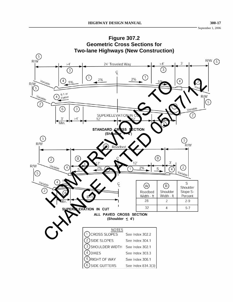
A 2-lane, 2-way roadbed consists of a 24-foot wide traveled way plus paved shoulders. In order to provide structural support, the minimum paved width of each shoulder shall be 2 feet. Development and maintenance of 4-foot paved shoulders should be considered when bicyclists are present. See Topic 1003 for information on bicycle design criteria and Figure 307.2 for typical 2-lane cross sections.
Shoulder widths based on design year traffic volumes shall conform to the standards given in Table 307.2.
On 2-lane roads with 4-foot shoulders, the shoulder slope may be increased to 7 percent for additional drainage capacity where a dike is used. With 2-foot shoulders the shoulder slope should be 2 percent without a dike, but may be increased to a maximum of 9 percent for additional drainage capacity with a dike.
Shoulder widths of 4 feet or less should be constructed in accordance with the "All Paved Cross Section" of Figure 307.2 in order to provide essentially the same structural section throughout the full roadbed width.
Minimum width of 2-lane State highways functionally classified as collectors may be as
given in Exhibit 6-5 of AASHTO, A Policy on Geometric Design of Highways and Streets. Up-to-date information on the functional classification of State highways may be obtained from Headquarters Office of Highway System Engineering.
Table 307.2
Shoulder Widths for Two-lane Roadbed New Construction Projects
Two-way ADT (Design Year)
Shoulder Width(1) (ft)
Less than 400 2 or 4(2)
Over 400 8
Notes:
(1) See Index 1003.2 for shoulder requirements when bike lanes are present.
(2) Minimum bridge width is 32 feet (see Index 208.1).
307.3 Two-lane Cross Sections for RRR Projects Standards and guidelines for two-lane cross sections on RRR projects are found in Design Information Bulletin Number 79 (DIB 79), "Geometric Design Criteria for Resurfacing, Restoration, and Rehabilitation (RRR) and Certain Safety, Storm Damage, Protective Betterment, and Operational Improvement Projects." DIB 79 can be found on the HQ Division of Design website under Design Information Bulletins.
The purpose of RRR (also known as roadway rehabilitation) projects is to preserve and extend the design life of existing highways for a minimum of ten years and enhance highway safety. DIB 79 focuses on geometric design criteria developed for RRR projects. The designer must always emphasize implementation of cost-effective safety improvements where practical.
RRR design criteria apply to all structure and roadway RRR projects on two-lane conventional highways and three-lane conventional highways not classified as multilane conventional highways.
RRR design criteria also apply to certain storm damage, protective betterment, operational, and
HDM PREVIO
US TO
CHANGE DATED 05
/07/12

300-16 HIGHWAY DESIGN MANUAL September 1, 2006
safety nonfreeway improvement projects that are considered spot locations as described in detail in DIB 79.
RRR criteria apply to geometric design features such as lane and shoulder widths, horizontal and vertical alignment, stopping sight distance, structure width, cross slope, superelevation, side slope, clear recovery zone, and intersections. They may also apply to such features as curb ramps, pavement edge drop, dike, curb and gutter, sidewalk, and drainage.
307.4 Multilane Divided Cross Sections The general geometric features of multilane divided cross sections are shown in Figure 307.4.
Divided highways may be designed as two separate one-way roads where appropriate to fit the terrain. Economy, pleasing appearance, and safety are factors to be considered in this determination. The alignment of each roadway may be independent of the other (see Indexes 204.8 and 305.6). Optional median designs may be as shown on Figure 305.6.
307.5 Multilane All Paved Cross Sections with Special Median Widths A multilane cross section with a narrow median is illustrated in Figure 307.5. This section is appropriate in special circumstances where a wider median would not be justified. It should not be considered as an alternative to sections with the median widths set forth under Index 305.1. It may be used under the following conditions:
(a) Widening of existing facilities.
(b) Locations where large excavation quantities would result if a multilane roadway cross section with a basic median width were used. Examples are steep mountainous terrain and unstable mountainous areas.
(c) As an alternate cross section on 2-lane roads having frequent sight distance restrictions.
The median width should be selected in accordance with the criteria set forth in Index 305.1(3).
In general, the outside shoulder should be 8 feet wide (10 feet on freeways and expressways) as
mandated in Table 302.1. Where large excavation quantities or other factors generate unreasonable costs, 4-foot shoulders may be considered. However, a design exception is required except where 4-lane passing sections are constructed on 2-lane highways. Where the roadbed width does not contain 8-foot shoulders, emergency parking areas clear of the traveled way should be provided by using daylighted cuts and other widened areas which develop during construction.
307.6 Multilane Cross Sections for RRR Projects RRR projects on freeways, expressways, and multilane conventional highways are generally required to meet new construction standards.
For additional information, see Design Information Bulletin Number 79, "Geometric Design Criteria for Resurfacing, Restoration, and Rehabilitation (RRR) and Certain Safety, Storm Damage, Protective Betterment, and Operational Improvement Projects.”
Topic 308 - Cross Sections for Roads Under Other Jurisdictions
308.1 City Streets and County Roads The width of local roads and streets that are to be reconstructed as part of a freeway project should conform to AASHTO standards if the local road or street is a Federal-aid route. Otherwise the cross section should match the width of the city street or county road adjoining the reconstructed portion, or the cross section should satisfy the local agency's minimum standard for new construction.
Where a local facility within the State right of way crosses over or under a freeway or expressway but has no connection to the State facility, the minimum design standards for the cross section of the local facility within the State's right of way shall be those found in AASHTO.
AASHTO standards for local roads and streets are given in AASHTO, A Policy on Geometric Design of Highways and Streets.
If the local agency has standards that exceed AASHTO standards, then the local agency standards should apply.
HDM PREVIO
US TO
CHANGE DATED 05
/07/12
HIGHWAY DESIGN MANUAL 300-17 September 1, 2006
Figure 307.2 Geometric Cross Sections for
Two-lane Highways (New Construction)
HDM PREVIO
US TO
CHANGE DATED 05
/07/12

300-18 HIGHWAY DESIGN MANUAL September 1, 2006
Figure 307.4 Geometric Cross Sections for Freeways and Expressways
HDM PREVIO
US TO
CHANGE DATED 05
/07/12

HIGHWAY DESIGN MANUAL 300-19 September 1, 2006
Figure 307.5 Geometric Cross Sections for All Paved Multilane Highways
HDM PREVIO
US TO
CHANGE DATED 05
/07/12

300-20 HIGHWAY DESIGN MANUAL September 28, 2011
It is important to note that AASHTO, A Policy on Geometric Design of Highways and Streets, standards are based on functional classification and not on a Federal-aid System.
Chapter 1 of AASHTO, A Policy on Geometric Design of Highways and Streets, list standards for the following six functional classes:
• Local rural roads • Local urban streets • Rural collectors • Urban collectors • Rural arterials • Urban arterials
AASHTO, A Policy on Geometric Design of Highways and Streets, gives minimum lane and shoulder widths. When selecting a cross section, the effects on capacity of commercial vehicles and grades should be considered as discussed under Topic 102 and in the Transportation Research Board, Highway Capacity Manual.
The minimum width of 2-lane overcrossing structures shall not be less than 28 feet curb to curb. Also see Index 208.1(2) and Index 307.3.
If the local agency has definite plans to widen the local street either concurrently or within 5 years following freeway construction, the reconstruction to be accomplished by the State should generally conform to the widening planned by the local agency. Stage construction should be considered where the planned widening will occur beyond the 5-year period following freeway construction or where the local agency has a master plan indicating an ultimate width greater than the existing facility. Where an undercrossing is involved, the initial structure construction should provide for ultimate requirements.
Where a local facility crosses over or under a freeway or expressway and connects to the State facility (such as ramp terminal intersections), the minimum design standards for the cross section of the local facility shall be at least equal to those for a conventional highway with the exception that the outside shoulder width shall match the approach roadway, but not less than 4 feet (shoulder width should not be less than 5 feet where curbs with 2-foot gutter pans are
proposed and bicycle use is expected).
Topic 309 - Clearances
The minimum width for two-lane overcrossings at interchanges shall be 40 feet curb-to-curb.
309.1 Horizontal Clearances (1) General. The horizontal clearance to all
roadside objects should be based on engineering judgment with the objective of maximizing the distance between roadside objects and the edge of traveled way. Engineering judgment should be exercised in order to balance the achievement of horizontal clearance objectives with the prudent expenditure of available funds.
Certain yielding objects, such as sand filled barrels, metal beam guardrail, breakaway wood posts, etc. may encroach within the clear recovery zone (see Index 309.1(2)). While these objects are designed to reduce the severity of accidents, efforts should be made to maximize the distance between any object and the edge of traveled way.
Clearances are measured from the edge of the traveled way to the nearest point on the obstruction (usually the bottom). Consideration should be given to the planned ultimate traveled way width of the highway facility. Horizontal clearances greater than those cited below under subsection (3) - "Minimum Clearances" shall be provided where necessary to meet horizontal stopping sight distance requirements. See subsection (4) for high speed rail clearance guidance. See discussion on "... technical reductions in design speed..." under Topic 101.
(2) Clear Recovery Zone (CRZ). The roadside environment can and should be made as safe as practical. A clear recovery zone is an unobstructed, relatively flat (4:1 or flatter) or gently sloping area beyond the edge of the traveled way which affords the drivers of errant vehicles the opportunity to regain control. The AASHTO Roadside Design Guide provides detailed design guidance for
HDM PREVIO
US TO
CHANGE DATED 05
/07/12

HIGHWAY DESIGN MANUAL 300-21 September 28, 2011
creating a forgiving roadside environment. See also Index 304.1 regarding side slopes.
The following clear recovery zone widths are the minimum desirable for the type of facility indicated. Consideration should be given to increasing these widths based on traffic volumes, operating speeds, terrain, and costs associated with a particular highway facility:
• Freeways and Expressways – 30 feet
• Conventional Highways – 20 feet*
* On conventional highways with posted speeds less than or equal to 40 mph and curbs, clear recovery zone widths do not apply. See minimum horizontal clearance, Index 309.1(3)(c).
Fixed objects including bridge piers, abutments, retaining walls, and noise barriers closer to the edge of traveled way than the distances listed above should be eliminated, moved, redesigned to be made yielding, or
(a) Fixed objects should be eliminated or moved outside the clear recovery zone to a location where they are unlikely to be hit.
shielded in accordance with the following guidelines:
(b) If sign posts six inches or more in any dimension or light standards cannot be eliminated or moved outside the clear recovery zone, they should be made yielding with a breakaway feature.
(c) If a fixed object cannot be eliminated, moved outside the clear recovery zone, or modified to be made yielding, it should be shielded by guardrail or a crash cushion.
Shielding must be in conformance with the guidance found in Chapter 7 of the Traffic Manual. For input on the need for shielding at a specific location, consult District Traffic Operations.
When the planting of trees is being considered, see the additional discussion and standards in Chapter 900.
Where compliance with the above stated clear recovery zone guidelines are impractical, the minimum horizontal clearance cited below shall apply to the unshielded fixed object. These minimum horizontal clearances apply to yielding objects as well.
(3) Minimum Clearances. The following minimum horizontal clearances shall apply to all objects that are closer to the edge of traveled way than the clear recovery zone distances listed above:
(a) The minimum horizontal clearance to all objects, such as bridge rails and safety-shaped concrete barriers, as well as sand-filled barrels, metal beam guardrail, etc., on all freeway and expressway facilities, including auxiliary lanes, ramps, and collector roads, shall be equal to the standard shoulder width of the highway facility as stated in Table 302.1. A minimum clearance of 4 feet shall be provided where the standard shoulder width is less than 4 feet. Approach rail connections to bridge rail may require special treatment to maintain the standard shoulder width.
(b) The minimum horizontal clearance to walls, such as abutment walls, retaining walls in cut locations, and noise barriers on all facilities, including auxiliary lanes, ramps and collector roads, shall not be less than 10 feet.
(c) On conventional highways, frontage roads, city streets and county roads (all without curbs), the minimum horizontal clearance shall be the standard shoulder width as listed in Tables 302.1 and 307.2, except that a minimum clearance of 4 feet shall be provided where the standard shoulder width is less than 4 feet. For RRR projects, widths are provided in DIB 79.
On conventional highways with curbs, typically in urban conditions, a minimum horizontal clearance of 1 feet 6 inches should
HDM PREVIO
US TO
CHANGE DATED 05
/07/12

300-22 HIGHWAY DESIGN MANUAL September 28, 2011
be provided beyond the face of curbs to any obstruction.
On curbed highway sections, a minimum clearance of 3 feet should be provided along the curb returns of intersections and near the edges of driveways to allow for design vehicle offtracking (see Topic 404). Where sidewalks are located immediately adjacent to curbs, fixed objects should be located beyond the back of sidewalk to provide an unobstructed area for pedestrians.
In areas without curbs, the face of Type 60 concrete barrier should be constructed integrally at the base of any retaining, pier, or abutment wall which faces traffic and is 15 feet or less from the edge of traveled way (right or left of traffic and measured from the face of wall).
The minimum width of roadway openings between Temporary Railing (Type K) on bridge deck widening projects should be obtained from the District Permit Engineer.
See Index 1102.2 for the treatment of noise barriers.
The Regional Permit Manager should be consulted on the use of the route by overwidth loads.
See Chapter 7 of the Traffic Manual for other requirements pertaining to clear recovery zone, guardrail at fixed objects and embankments, and crash cushions.
(4) High Speed Rail Clearances. When a high speed rail corridor is to be constructed longitudinally to a freeway, expressway or a conventional highway with posted speeds over 40 mph, the nearest fixed object or feature associated with the operation of the rail facility should be located a minimum of 52 feet horizontally from the planned ultimate edge of the traveled way.
specific location, consult District Traffic Operations.
See Index 62.10 for the definition of high speed rail. The terrain and the required highway features between the edge of traveled way and the rail facility to be constructed must be evaluated to determine on a case-by-case basis whether or not shielding behind guardrail, barrier or other safety device in conformance with the guidance found in Chapter 7 of the Traffic Manual is needed. For input on the need for shielding at a
309.2 Vertical Clearances (1) Major Structures.
(a) Freeways and Expressways, All construc-tion except overlay projects – 16 feet 6 inches shall be the minimum vertical clearance over the roadbed of the State facility (e.g., main lanes, shoulders, ramps, collector-distributor roads, speed change lanes, etc.).
(b) Freeways and Expressways, Overlay Projects – 16 feet shall be the minimum vertical clearance over the roadbed of the State facility.
(c) Conventional Highways, Parkways, and Local Facilities, All Projects – 15 feet shall be the minimum vertical clearance over the traveled way and 14 feet 6 inches shall be the minimum vertical clearance over the shoulders of all portions of the roadbed.
(2) Minor Structures. Pedestrian over-crossings shall have a minimum vertical clearance 2 feet greater than the standard for major structures for the State facility in question.
Sign structures shall have a vertical clearance of 18 feet over the roadbed of the State facility.
(3) Rural Interstates and Single Routing in Urban Areas: This subset of the Interstate System is composed of all rural Interstates and a single routing in urban areas. Those routes described in Table 309.2B and Figure 309.2 are given special attention in regards to minimum vertical clearance as a result of agreements between the FHWA and the Department of Defense. Vertical clearance for structures on this system shall meet the standards listed above for freeways and expressways. In addition to the standards listed above, vertical clearances of less than 16 feet over any portion of this system will be subjected to extensive review by FHWA and must be approved by the Military Traffic Management Command Traffic Engineering Agency
HDM PREVIO
US TO
CHANGE DATED 05
/07/12

HIGHWAY DESIGN MANUAL 300-23 September 28, 2011
(MTMCTEA) in Washington D. C. Documentation in the form of a Design Exception Fact Sheet must be submitted to FHWA to obtain approval for less than 16 feet of vertical clearance. Vertical clearances of less than 16 feet over any Interstate will require FHWA/MTMCTE notification. See Robert L. Buckley’s memo dated March 30, 2000 to District Directors for more information on this subset of the Interstate system.
(4) General Information. The standards listed above and summarized in Table 309.2A are the minimum allowable on the State Highway system for the facility and project type listed. For the purposes of these vertical clearance standards, all projects on the freeway and expressway system other than overlay projects shall be considered to be covered by the "new construction" standard.
When approved by a design exception (see HDM Index 82.2) clearances less than the values given above may be allowed on a case by case basis given adequate justification based upon engineering judgment, economic, environmental or right of way considerations. Typical instances where lesser values may be approved are where the structure is protected by existing lower structures on either side or where a project includes an existing structure that would not be feasible to modify to the current standard. In no case should vertical clearance be reduced below 15 feet over the traveled way or 14 feet 6 inches over the shoulders over any portion of a State highway facility.
Efforts should be made to avoid decreasing the existing vertical clearance whenever possible and consideration should be given to the feasibility of increasing vertical clearance on projects involving structural section removal and replacement. Any project that would reduce vertical clearances below 16 feet 6 inches or lead to an increase in the vertical clearance should be brought to the attention of the Design Coordinator, the District Permit Engineer and the Regional Permit Manager at the earliest possible date.
The Regional Permit Manager should be informed of any changes (temporary or permanent) in vertical clearance.
(5) Federal Aid Participation. Federal-aid participation is normally limited to the following maximum vertical clearances unless there are external controls such as the need to provide for falsework clearance or the vertical clearance is controlled by an adjacent structure in a multi-structure interchange:
(a) Highway Facilities.
• 17 feet over freeways and expressways.
• 15 feet 6 inches over other highways (15 feet over shoulders).
• For pedestrian structures, 2 feet greater than the above values.
(b) Railroad Facilities.
• 23 feet over the top of rails for non-electrified rail systems.
• 24 feet 3 inches over the top of rails for existing or proposed 25 kv electrification.
• 26 feet over the top of rails for existing or proposed 50 kv electrification.
These clearances include an allowance for future ballasting of the rail facility. The cost of reconstructing or modifying any existing railroad-highway grade separation structure solely to accommodate electrification will not be eligible for Federal-aid highway fund participation. Where a rail system is not currently electrified, the railroad must have a plan adopted which specifies the intent to electrify the subject rail segment within a reasonable time frame in order to provide clearances in excess of 23 feet.
Any exceptions to the clearances listed above should be reviewed with the FHWA early in the design phase to ensure that they will participate in the structure costs. All excess clearances should be documented in the project files as to reasons and appropriate concurrences.
HDM PREVIO
US TO
CHANGE DATED 05
/07/12

300-24 HIGHWAY DESIGN MANUAL September 1, 2006
Table 309.2A Vertical Clearances
Traveled Way Shoulder
Freeways and Expressways, New Construction, Lane Additions, Reconstruction and Modification 16½ ft 16½ ft
Freeways and Expressways, Overlay Projects 16 ft 16 ft
All Projects on Conventional Highways and Local Facilities 15 ft 14½ ft
Sign Structures 18 ft 18 ft
Pedestrian and Minor Structures Standard + 2 ft See 309.2(2)
Structures on the Rural and Single Interstate Routing System See 309.2(3)
HDM PREVIO
US TO
CHANGE DATED 05
/07/12

HIGHWAY DESIGN MANUAL 300-25 October 4, 2010
Figure 309.2 Department of Defense
Rural and Single Interstate Routes
HDM PREVIO
US TO
CHANGE DATED 05
/07/12

300-26 HIGHWAY DESIGN MANUAL September 1, 2006
Table 309.2B California Routes on the Rural and Single Interstate Routing System
ROUTE FROM TO
I-5 U. S. Border I-805 just N. of U. S. Border
I-5 I-805 N. of San Diego I-405 near El Toro
I-5 I-210 N. of Los Angeles Oregon State Line
I-8 I-805 near San Diego Arizona State Line
I-10 I-210 near Pomona Arizona State Line
I-15 I-8 near San Diego Nevada State Line
I-40 Junction at I-15 near Barstow Arizona State Line
I-80 I-680 near Cordelia Nevada State Line
I-205 Junction at I-580 Junction at I-5
I-210 I-5 N. of Los Angeles I-10 near Pomona
I-215 I-15 near Temecula I-15 near Devore
I-280 Junction at I-680 in San Jose At or near south city limits of San Francisco to provide access to Hunter's Point
I-405 I-5 near El Toro Palo Verde Avenue just N. of I-605
I-505 Junction at I-80 Junction at I-5
I-580 I-680 near Dublin Junction at I-5
I-605 I-405 near Seal Beach I-210
I-680 Junction at I-280 in San Jose I-80 near Cordelia
I-805 I-5 just N. of U. S. Border I-5 N. of San Diego
HDM PREVIO
US TO
CHANGE DATED 05
/07/12
HIGHWAY DESIGN MANUAL 300-27 September 28, 2011 309.3 Tunnel Clearances (1) Horizontal Clearances. Tunnel construction
is so infrequent and costly that the width should be considered on an individual basis. For the minimum width standards for freeway tunnels see Index 309.1.
Normally, the minimum horizontal clearance on freeways should include the full roadbed width of the approaches.
In one-way tunnels on conventional highways the minimum side clearance from the edge of the traveled way shall be 4 feet 6 inches on the left and 6 feet on the right. For two-way tunnels, this clearance shall be 6 feet on each side.
(2) Vertical Clearances. The minimum vertical clearance shall be 15 feet measured at any point over the traveled way and 14 feet 6 inches above the gutter at the curb line. On freeways and expressways, the vertical clearance listed in Index 309.2(1)(a) shall be used. Cost weighed against the probability of over-height vehicles will be the determining factors.
309.4 Lateral Clearance for Elevated Structures Adequate clearance must be provided for maintenance, repair, construction, or reconstruction of adjacent buildings and of the structure; to avoid damage to the structure from a building fire or to buildings from a vehicle fire; to permit operation of equipment for fire fighting and other emergency teams. The minimum horizontal clearance between elevated highway structures, such as freeway viaducts and ramps, and adjoining buildings or other structures, shall be 15 feet for single-deck structures and 20 feet for double-deck structures. Spot encroachments on this clearance shall be approved in accordance with Index 82.2.
309.5 Structures Across or Adjacent to Railroads Regulations governing clearances on railroads and street railroads with reference to side and overhead
structures, parallel tracks, crossings of public roads, highways, and streets are established by the PUC.
(1) Normal Horizontal and Vertical Clearances. Although General Order No. 26-D specifies a minimum vertical clearance of 22 feet 6 inches above tracks on which freight cars not exceeding a height of 15 feet 6 inches are transported, a minimum of 23 feet should be used in design to allow for reballasting and normal maintenance of track. Railroads on which freight cars are not operated, should have a minimum vertical clearance of 19 feet.
At underpasses, General Order No. 26-D establishes a minimum vertical clearance of 14 feet above any public road, highway or street. However, the greater clearances specified under Index 309.2 shall be used.
In establishing the grade line, the District should consult the DES to obtain the depth of structures and false work requirements, if any (see Index 204.6(4)).
All curbs, including median curbs, should be designed with 10 feet of clearance from the track centerline measured normal thereto.
The principal clearances which affect the design of highway structures and curbs are summarized in Tables 309.5A and B. It should be noted that collision walls may be required for the clearances given in Columns (3) and (4) of Table 309.5B. Usually, no collision walls are required if the clearance 10 feet or more on tangent track and 11 feet or more on curved track.
Table 309.5A Minimum Vertical Clearances
Above Highest Rail Type of Operation
Type of Structure Normal Freight
No Freight Cars Operated
Highway overhead and other structures including through railroad bridges.
23' – 0" 19' – 0"
HDM PREVIO
US TO
CHANGE DATED 05
/07/12

300-28 HIGHWAY DESIGN MANUAL September 28, 2011
(2) Off-track Maintenance Clearance. The 18-foot horizontal clearance is intended for sections of railroad where the railroad company is using or definitely plans to use off-track maintenance equipment. This clearance is provided on one side of the railroad right of way.
On Federal-aid projects, where site conditions are such that off-track maintenance clearance at an overpass is obtained at additional cost, Federal-aid funds may participate in the costs of such overhead designs that provide up to 18 feet horizontal clearance on one side of the track. In such cases, the railroad is required to present a statement that off-track maintenance equipment is being used, or is definitely planned to be used, along that section of the railroad right of way crossed by the overhead structure.
(3) Walkway Clearances Adjacent to Railroads. All plans involving construction adjacent to railroads should be such that there is no encroachment on the walkway adjoining the track. Walkway requirements are set forth in General Order No. 118 of the PUC. Where excavations encroach into walkway areas, the contractor is required to construct a temporary walkway with handrail as set forth in the contract special provisions.
(4) Approval. All plans involving clearances from a railroad track must be submitted to the railroad for approval as to railroad interests. Such clearances are also subject to approval by the PUC.
To avoid delays, early consideration must be given to railroad problems when design is started on a project.
Topic 310 - Frontage Roads
310.1 Cross Section Frontage roads are normally relinquished to local agencies. When Caltrans and a county or city enter into an agreement (cooperative agreement, freeway agreement, or other type of binding agreement), the CTC may relinquish to the county or city any
frontage or service road or outer highway within that city or county. The relinquished right of way (called a collateral facility) should be at least 40 feet wide and have been constructed as part of a State highway project, but not as a part of the main State highway. Index 308.1 gives width criteria for city streets and county roads. These widths are also applicable to frontage roads. However, the minimum paved cross section for urban frontage roads shall be two 12-foot lanes with 4-foot outside shoulders. See Chapter 1000 for shoulder requirements when bicycles are present. The minimum paved cross section for rural frontage roads shall be 24 feet.
310.2 Outer Separation In urban areas and in mountainous terrain, the width of the outer separation should be a minimum of 26 feet from edge of traveled way to edge of traveled way. A greater width may be used where it is obtainable at reasonable additional cost, for example, on an urban highway centered on a city block and paralleling the street grid.
See Figure 307.4 for cross sections of outer separation and frontage road.
In rural areas, other than mountainous terrain, the outer separation should be a minimum of 40 feet wide from edge of traveled way to edge of traveled way.
310.3 Headlight Glare Care should be taken in design of new frontage roads to avoid the potential for headlight glare interfering with the vision of motorists traveling in opposite directions on the frontage roads and in the outer freeway lanes. The preferred measures to prevent headlight glare interference on new construction are wider outer separations, revised alignment and raised or lowered profiles.
HDM PREVIO
US TO
CHANGE DATED 05
/07/12

HIGHWAY DESIGN MANUAL 300-29 September 1, 2006
Table 309.5B
Minimum Horizontal Clearances to Centerline of Nearest Track
Curved Track Clearances
When Space is Limited(1)
Type of Structure Off-track
Maintenance Clearance
Tangent Track Clearance Normal Curved
Track (1)
Clearance
Curves of 0° to 12°
Curves of 12° or more
Through rail- road bridge None 8' – 0"(2)(4)
9' – 0"(2)(4)
Highway over- head and other structures
18' – 0" clear to face of pier or abutment on side railroad requires for equipment road.
8' – 6"(4) 9' – 6"(4) 8' – 6"
(Min.)(3)
8' – 6" + ½"(3) per degree of curve.
Curbs 10' – 0"
Notes:
(1) The minimum, in general, is one foot greater than for tangent track.
(2) With approval of P.U.C.
(3) Greater clearance necessary if walkway is required.
(4) Collision walls may be required. See Index 309.5(1).
HDM PREVIO
US TO
CHANGE DATED 05
/07/12