on the topology of sheet metal parts - mit
TRANSCRIPT

1
On the Topology of Sheet Metal Parts H. Lipson and M. Shpitalni
Laboratory for Computer Graphics and CAD, Faculty of Mechanical Engineering, Technion, Haifa 32000, Israel
Abstract - This paper analyzes the topological properties of sheet metal parts represented schematically (zero thickness, zero bend radii). Although such parts are usually non-manifold objects, the paper establishes a general topological invariant f = s + b + e + w - v - gnm + m regarding the number of facets, components, bends, free edges, welds, vertices holes and volumes, respectively. Corresponding Euler operators are derived, providing a basis for a modeling system for sheet metal parts. With this invariant, it is possible to reason about manufacturing processes, such as number of components and arrangement of bend lines and weld lines, using only a single qualitative model of the product. This capability is particularly useful in the preliminary stage of conceptual design. A corresponding topological invariant v-e+f=s+m-gnm is also proposed for general sheet models and thin walled objects.
1. INTRODUCTION
Sheet metal parts are often represented schematically by a structure of zero-thickness facets connected with zero-radius bend lines, as illustrated in Fig. 1. While such a representation does not always constitute a manifold model, examination of the topology of such products does reveal some interesting relationships. Formulation of these characteristics makes it possible to draw conclusions about various parameters in the manufacturing process of the product, such as minimum number of required components, arrangement of bend lines and connecting (weld) lines, flat patterns, etc. In addition, this topological invariant can provide a basis for modeling sheet metal parts, classifying parts, and detecting errors, both in representation and in design. Moreover, since only the topology of the sheet metal part is required to extract this information, only a qualitative model is necessary, without accurate dimensions of any kind.
In this paper, previous work in the area of sheet metal design and related topological reasoning is reviewed. Next, the basic relationships between the fundamental elements of a sheet metal part are described. From these relationships, a topological invariant is derived that is applicable to a sheet metal part both in its final form and in

2
intermediate bending stages. This invariant is then used to analyze various manufacturing alternatives. The principle of Euler operators for manifold objects is then applied to create similar topological operators for sheet metal parts. Finally, the proposed topological invariant is adapted to general non-manifold sheet models and thin walled objects.
(a) (b)
Fig 1. Schematic sheet metal products
The paper aims to propose the following:
¥ A topological invariant for all sheet metal parts and thin walled objects which may be used as a necessary condition for topological validity and reasoning about topological configurations.
¥ A set of topological operators which may be used as basic building blocks for a model representation of sheet metal parts in a sheet modeling system.
2. RELATED WORK
Several CAD/CAM systems have been developed for modeling, process planning and manufacturing sheet metal products, including the systems proposed by de Vries et al [1], Shpitalni [2], and Inui et al [3]. Lee et al [4] describe the use of sheets for efficient modeling of general thin objects. Some systems model the sheet metal product, including its thickness and bend fillets, using traditional solid modeling techniques. A more recent approach has been to model the sheet metal product in a schematic form with zero thickness and zero bend radii, along with manufacturing constraints [2]. However, no formal analysis has been made of this kind of representation and its underlying topology.
Sheet metal parts in bent form typically constitute non-manifold objects. A 2-manifold object is defined as a surface on which every point has a neighborhood that is homeomorphic to a 2-disk [5]. A manifold object can be classified as genus zero if

3
it can be deformed continuously into a sphere, that is, if it is homeomorphic to a sphere. A manifold object of genus one can be deformed continuously into the shape of a torus, and so on. According to the above definition, a manifold does not include boundaries. Objects containing any free edges (Figs. 1(a) and 1(b)) or surface forks (Fig. 1(b)) are not 2-manifold, and are generally termed non-manifold objects. A manifold with a single continuous boundary (homeomorphic to a semi-sphere) is sometimes referred to as a manifold with boundary. Since Requicha [6] formally introduced regularized r-sets, solid modeling has developed rapidly, especially for manifold geometries. Various data structures exist, most based internally on manifold topology and manifold operators; one example is Mantyla's approach [5]. Generalizing solid modeling schemes to include wireframes and surfaces was subsequently explored by Weiler [7], for example. Recently, interest in non-manifold topology has grown. Non-manifold extensions to solid modeling are typically implemented by using a more general formulation that includes non-manifold elements, such as the cusps, disks, zones, regions and walls proposed by Gursoz et al [8] or the shells, complexes, cavities and holes of various types suggested by Masuda et al [9] and others. Application of Euler characteristics and topology in design is also discussed by Lear [10] and Lee [4]. A more detailed taxonomy of geometric and topological models is provided by Takala [11], Mortenson [12] and Mantyla [5]. While these works tend to provide increasingly general formulations, none has concentrated on specific modeling tasks, such as modeling of sheet metal parts. These parts are usually non-manifold and thus comply with general formulae such as those discussed by Gursoz et al [8] and Masuda et al [9]; nonetheless, they are still confined to a relatively narrow topological domain and may therefore use simpler relationships. For example, they cannot directly include solids or detached edges and vertices. On the other hand, they include special entities such as weldings, which can be treated differently than simple free edges. These special conditions are considered in this paper.
3. THE RELATIONSHIP BETWEEN THE FUNDAMENTAL ELEMENTS OF A SHEET METAL PART
A sheet metal product consists of one or more pieces of sheet metal that are bent and welded along straight lines. Hence, the product is composed of planar facets joined along bend lines or weld lines. The term weld is used in a general context to denote any kind of physical bonding. The part also contains free edges. Bend and weld lines should be distinguished from touching free edges which happen to meet but do not form a physical connection of any type. All line types meet at vertices of the product. These terms are illustrated in Fig. 2 below.

4
Free edgesBend line
Vertices
FacetWeld line
A single component, No volumes, No holes
Fig 2. Basic elements of a sheet metal product
The existence of a constant relationship among these elements of a sheet metal part composed of one or more components is established in the following sections.
The relationship is developed according to the following steps:
1. A relationship based on Euler-Poincar� formula is derived for an unbent part.
2. The concepts of non-manifold genus, weld lines and volumes are defined. Corresponding terms are added to the relationship, which retains its validity for the flat pattern.
3. This relationship is shown to remain valid during any bending and welding steps through systematic consideration of the possible topological changes.
3.1 THE FLAT PATTERN
We start by examining a sheet metal product in its initial unbent form, i.e., its flat pattern, as illustrated in Fig. 3. The flat pattern is a special case of a sheet metal product in which all of the bends are at zero degrees. We proceed to analyze the schematic drawing of a flat pattern as a topological graph consisting of edges (corresponding to unbent bend lines, and free edges), vertices, and faces (corresponding to the unbent facets).
Since, by definition, bend lines and free edges intersect only at vertices and facet borders consist of free edges or bend lines, it can be concluded that the graph is planar and that each face of the graph corresponds to a facet of the product. This can be seen in the correspondence between Figs. 3(a) and 3(b).

5
facet
bend
free edge
face
edge
edge
vertex
(a) (b)
Fig 3. (a) A flat pattern of a sheet metal part, and (b) the corresponding planar graph
Euler-Poincar�'s formula for a single component planar graph [5] asserts that
f + v - e = 2 (1)
where f represents the number of faces of the graph (including the exterior face), v the number of vertices, and e the number of edges. In a flat pattern of a sheet metal product, the exterior face does not represent a facet. (Note that a planar graph object without an exterior face is sometimes referred to as a 2-manifold with boundary). The corresponding formula for a graph representing a flat pattern of a sheet metal part would therefore take the form
f + v - e = 1 (2)
A more general version of Euler-Poincar�'s formula for a multiple component planar graph states that
f + v - e = 2 s (3)
where s is the number of graph components (or shells, as often termed in the solid modeling context [5]). A graph is said to have several components if it consists of disconnected subgraphs. Since each component contains an exterior face which is to be ignored for sheet metal products, we arrive at the corresponding relationship for sheet metal parts:
f + v - e = s (4)
where s represents the number of disconnected flat patterns, f represents the number of facets in the flat patterns, v the number of vertices, and e the number of edges (including bend lines and free edges).
6
So far, the term e has denoted the number of all the lines in the flat pattern, both free edges and bend lines. To proceed, we must distinguish between the two types. The symbol b will denote the number of bend lines, and e will therefore now represent only the number of remaining free edges. The term free edge relates to any edge that is not a bend line (and, later on, not a weld line). A free edge can be internal in any other sense. Accordingly, modifying and reordering Eq. (4) results in:
f = s + (b + e) - v (5)
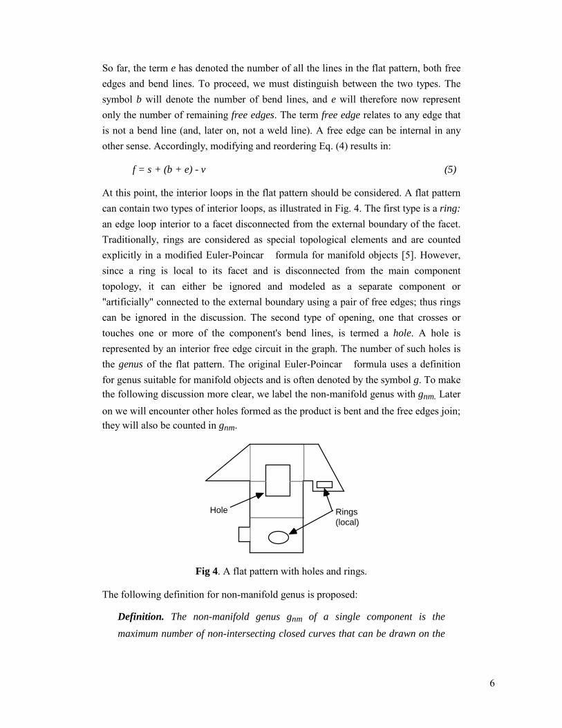
At this point, the interior loops in the flat pattern should be considered. A flat pattern can contain two types of interior loops, as illustrated in Fig. 4. The first type is a ring: an edge loop interior to a facet disconnected from the external boundary of the facet. Traditionally, rings are considered as special topological elements and are counted explicitly in a modified Euler-Poincar� formula for manifold objects [5]. However, since a ring is local to its facet and is disconnected from the main component topology, it can either be ignored and modeled as a separate component or "artificially" connected to the external boundary using a pair of free edges; thus rings can be ignored in the discussion. The second type of opening, one that crosses or touches one or more of the component's bend lines, is termed a hole. A hole is represented by an interior free edge circuit in the graph. The number of such holes is the genus of the flat pattern. The original Euler-Poincar� formula uses a definition for genus suitable for manifold objects and is often denoted by the symbol g. To make the following discussion more clear, we label the non-manifold genus with gnm. Later on we will encounter other holes formed as the product is bent and the free edges join; they will also be counted in gnm.
Rings (local)
Hole
Fig 4. A flat pattern with holes and rings.
The following definition for non-manifold genus is proposed:
Definition. The non-manifold genus gnm of a single component is the maximum number of non-intersecting closed curves that can be drawn on the

7
part surface before partitioning its surface into two previously connected disconnected regions.
For a multi-component part, the genus is the sum of the genuses of the individual components. Note that for the purpose of this definition, a surface is considered two-sided, and the sides meet at free edges. For example, a flat plate has one surface that spans both sides of the plate, since the two sides are connected along the free edges. If it has no holes, then no closed curve may be drawn on it without partitioning the surface into two disconnected regions. A hollow sheet metal sphere, on the other hand, has two surfaces, internal and external, which are separate because they have no common edge. However, in the case of the sphere as well, no non-partitioning curve can be drawn, and hence its non-manifold genus gnm is zero. By the above definition, the genus of an object corresponds to the connectivity of its surface, where connectivity is a topological quality which measures the number of topologically different paths connecting any two regions on a surface. It is easy to verify, using this criterion, that gnm=1 in the flat pattern shown in Fig. 5 (a), (ignoring the local rings); in Fig. 5 (b), gnm=1 as well, but in the flat pattern in Fig. 5 (c), gnm=0 . Similarly, for a torus, gnm would be 2, because one closed curve could be drawn on the external surface and another on the internal surface and still no previously connected surface points would be partitioned. (See Section 5 for further discussion of general geometry).
(a) (b) (c)
Non-partitioning closed curve
Non-partitioning closed curve
Fig 5. Determining the genus of a sheet metal part.
Any hole is a face of the graph but does not represent a facet in the unbent part; therefore, it is not counted as a facet, and hence
f = s + b + e - v - gnm (6)

8
3.2 BENDING AND WELDING
The analysis so far has applied to a flat layout. We now proceed to bend the flat pattern into a full product, showing that Eq. (6) can be modified to include terms for weld lines and volumes and still hold true.
As the bend lines are folded, some free edges and vertices may join together to form so-called weld lines. (If they are not welded together, they remain two distinct free edges, and the topology is not changed.) The following definition of a weld line is used:
Definition. A weld line is a continuous line which is a common boundary of two or more facets.
The number of weld lines is denoted by w. Note that according to this definition, a bend line is interchangeable with a weld line. This is true both from a manufacturing point of view and from a mathematical standpoint, as will become apparent below.
Additional loops (holes) may be created and some volumes may be sealed off when bend lines are bent. Define a volume as follows:
Definition. A volume corresponds to a closed surface from which no curve can be cast to the exterior (infinity or another exterior surface).
Volumes are counted using the term m. Initially, in the flat pattern, there are no weld lines, i.e. w=0, and no volumes, i.e. m=0. Hence Eq. 6 can be modified to include weld lines and volumes. Since m≡ 0 and w≡ 0 for the flat pattern, Eq. (7) holds true for a flat pattern
f = s + b + e + w - v - gnm + m (7)
We will now show that this relationship also holds true for bent and welded parts.
During the bending and welding of a flat pattern into a final product, free edges join together in various ways. The bending operation itself does not change the topology or the count of the fundamental elements. The welding operation, however, joins free edges, vertices and bend lines, causing the topology to change. We denote the changes in f, s, b, e, w, v, gnm and m by ֶf, ֶs, ֶb, ֶe, ֶw, ֶv, ֶgnm and ֶm, respectively.
1. During the weld operation, two lines merge into one. Each of the two lines may be either a free edge, a weld line or a bend line. The overall joining effect is that ֶb+ֶe+ֶw = -1 always.

9
2. The two joining lines may originally have no common vertices, may share one vertex, or may share both vertices. We shall consider each case separately (refer to Figure�6).
2.1 No common vertices: If the lines share no common vertices, then merging the two lines causes two vertices to vanish, thus ֶv = -2. The two original lines may have belonged either to one component or to two separate components.
2.1.1 If the two lines belonged to two separate components (Fig 6(a)), then the merge united them so that ֶs = -1. Any partitioning curve across the joint will partition the component back into two parts, and therefore cannot contribute to the genus. Thus ֶgnm = 0.
2.1.2 If the two lines belong to the same component (Fig 6(b)), then ֶs=0 but the genus is increased because, according to the definition of gnm, a single
closed partitioning-curve can now be traced round the two-sided merged line without partitioning the component; thus ֶgnm = +1.
The number of volumes is left unmodified in this case, because any ray cast out between the two original lines can still be cast out between their adjacent continuations; thus ֶm = 0. Collectively, ֶs-ֶv-ֶgnm+ֶm = +1.
2.2. One common vertex: If the lines share one common vertex (Fig 6(c)), then merging the two lines causes one vertex to vanish; thus ֶv = -1. The two original lines must have originated from the same component because they shared a vertex; therefore ֶs=0. Also the genus does not change because connectivity is not modified, i.e. no existing paths removed or new paths formed; therefore ֶgnm = 0. The number of volumes is also left unmodified in this case because any ray cast out between the two original lines can still be cast out between their adjacent continuations on the side of the vanishing vertex; thus ֶm = 0. Collectively, ֶs-ֶv-ֶgnm+ֶm = +1.
2.3. Two common vertices: If the lines share two common vertices, then they originally formed a hole. Merging the two lines causes no vertex to vanish; thus ֶv = 0. The two original lines must have originated from the same component because they shared vertices; therefore ֶs=0. Any partitioning curves on the surface can be arranged so that not more than one passes through the hole created by the two lines (for proof see Appendix A.) Two cases must be distinguished:
2.3.1 If a closed curve on the surface passed between the lines once (Fig 6(d)), then joining the lines would eliminate that curve; therefore by the definition of non-manifold genus, ֶgnm = -1. In this case, the number of

10
volumes does not change because if a ray is cast through, it can still be cast by following the curve continuation and ֶm = 0.
2.3.2 If, on the other hand, no closed curve on the surface could pass once between the lines (Fig 6(e)) then the two lines must have formed a single entry into a volume. Therefore, joining the lines did not change the genus, ֶgnm = 0, but did create a volume, ֶm = +1.
Collectively, ֶs-ֶv-ֶgnm+ֶm = +1.
3. The number of facets does not change by joining the lines; therefore ֶf = 0.
Combining ֶf = 0 with ֶb+ֶe+ֶw = -1 and t ֶs-ֶv-ֶgnm+ֶm = 1 yields no overall
change in the value of Eq. (7).
Joining Two Entities
From Same Component
From Different Components
Two common vertices
No common vertices One common
vertex
(a)
(c)
(b)
(d)
(e)
Fig 6. Alternatives in joining two lines.
It can therefore be concluded that Eq. (7) holds true both for final products and products at intermediate bending stages. Moreover, from the preceding analysis it is evident that a collection of objects composed of facets, bends, welds, free edges, vertices and volumes can form a valid schematic model of a sheet metal part if and only if the number of these elements satisfies Eq. (7). Hence, Eq. (7) can be considered as a necessary integrity criterion for such schematic models. Evidently, additional criteria regarding entity configuration and metric considerations must also be satisfied to ensure full geometrical validity. These additional criteria are not treated

11
in this paper; however some are provided to illustrate the utility of the topological invariant.
3.3 EXAMPLES
An additional constraint requires that the minimum number of bends or welds required to keep the f facets of a component together is f-1. Consequently, the number of bends/welds required to construct s components is at least f-s. Hence,
b + w ³ f - s (8)
Combining Eqs. (7) and (8) yields the difference d between the actual number of bend/weld lines in a product (Eq. 7) and the required number of bend/weld lines for construction (holding the component together) (Eq. 8):
d = v - e + gnm - m (9)
The following examples show how this difference d can be used in analyzing a schematic sheet metal product.
3.3.1 EXAMPLE 1
First, consider the product illustrated in Fig. 1(a). Ignoring the four elliptic holes at the front (local "rings" that do not touch any bend/weld lines), there are 26 vertices, 24 free edges, 12 bend/weld lines and 11 faces. There is one component, so that s=1, and there are no holes, so that gnm=0, and no closed volumes, so m=0. Substituting into (Eq. 7), we obtain
b + w = f - s - e + v + gnm - m = 11 - 1 - 24 + 26 + 0 - 0 = 12;
thus, (Eq. 7) holds true for this product. Notice also that according to (9)
d = v - e + gnm - m = 26 - 24 + 0 - 0 = 2
which implies that of these 12 bend/weld lines, two are not strictly required for the product to be in one piece. The formula does not indicate which of the 12 bend/welds are redundant but it can readily be seen that, for example, the two vertical "welds" at the left side of the product can be undone without the product falling apart.
3.3.2 EXAMPLE 2
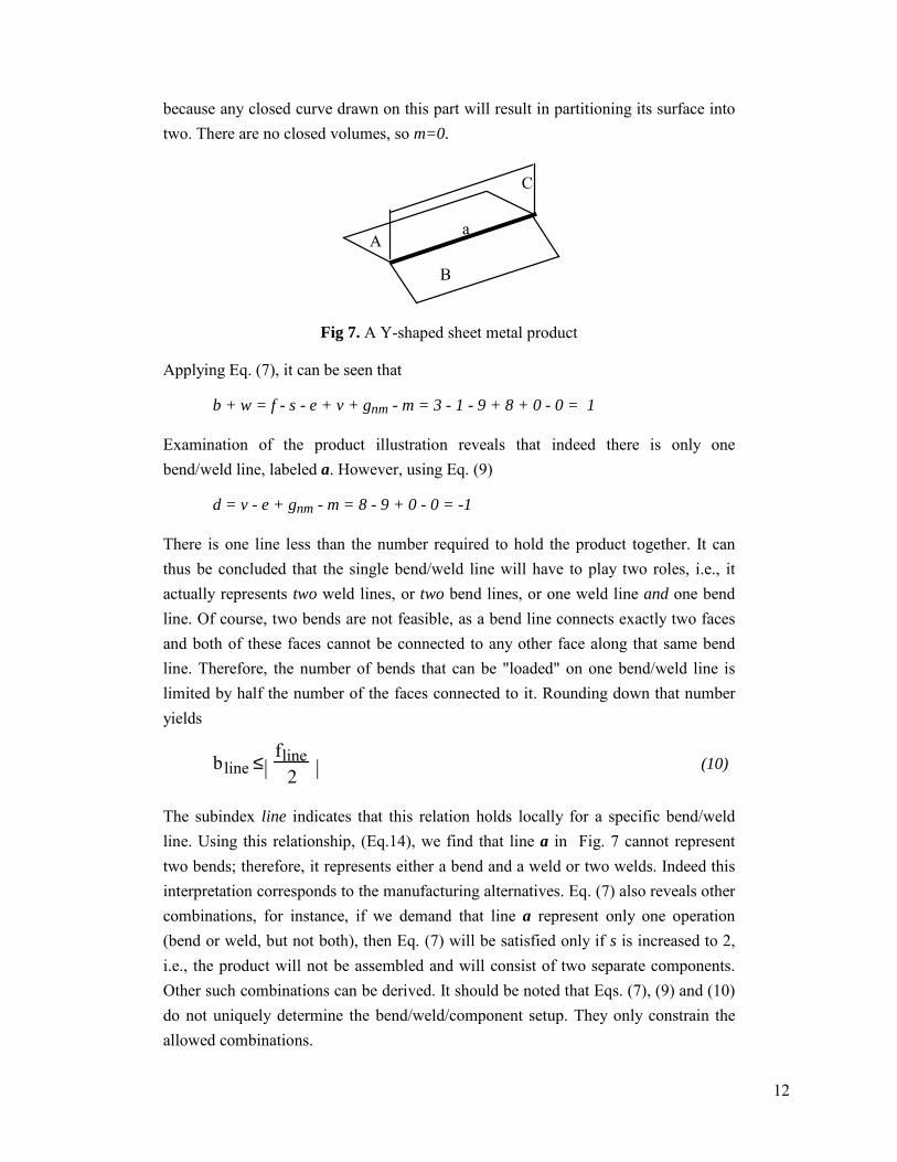
Consider the product illustrated in Fig. 7, a schematic sheet metal product in the shape of an extruded "Y". This product in its final form should be one piece, implying that s = 1. There are 3 faces, 8 vertices and 9 free edges. The genus of the product is 0
12
because any closed curve drawn on this part will result in partitioning its surface into two. There are no closed volumes, so m=0.
aA
B
C
Fig 7. A Y-shaped sheet metal product
Applying Eq. (7), it can be seen that
b + w = f - s - e + v + gnm - m = 3 - 1 - 9 + 8 + 0 - 0 = 1
Examination of the product illustration reveals that indeed there is only one bend/weld line, labeled a. However, using Eq. (9)
d = v - e + gnm - m = 8 - 9 + 0 - 0 = -1
There is one line less than the number required to hold the product together. It can thus be concluded that the single bend/weld line will have to play two roles, i.e., it actually represents two weld lines, or two bend lines, or one weld line and one bend line. Of course, two bends are not feasible, as a bend line connects exactly two faces and both of these faces cannot be connected to any other face along that same bend line. Therefore, the number of bends that can be "loaded" on one bend/weld line is limited by half the number of the faces connected to it. Rounding down that number yields
bline ≤ fline2
ℜℜ�ℜ
ℜℜ�ℜ
(10)
The subindex line indicates that this relation holds locally for a specific bend/weld line. Using this relationship, (Eq.14), we find that line a in Fig. 7 cannot represent two bends; therefore, it represents either a bend and a weld or two welds. Indeed this interpretation corresponds to the manufacturing alternatives. Eq. (7) also reveals other combinations, for instance, if we demand that line a represent only one operation (bend or weld, but not both), then Eq. (7) will be satisfied only if s is increased to 2, i.e., the product will not be assembled and will consist of two separate components. Other such combinations can be derived. It should be noted that Eqs. (7), (9) and (10) do not uniquely determine the bend/weld/component setup. They only constrain the allowed combinations.

13
3.3.3 EXAMPLE 3
Consider now a slightly different arrangement of 3 facets, as shown in Fig. 8 below.
A
C
B
a
bc
Fig 8. A schematic sheet metal corner
This product is composed of one component, i.e., s=1, has 6 free edges, 7 vertices, 3 faces, 0 volumes and genus 0. According to Eq. (7),
b + w = f - s - e + v + gnm - m = 3 - 1 - 6 + 7 + 0 - 0 = 3
An examination of the product reveals that indeed there are 3 bend/weld lines, labeled a, b and c. According to Eq. (9),
d = v - e + gnm - m = 7 - 6 + 0 - 0 = 1
implying that there is one excessive bend/weld in this product from a constructive point of view. Indeed, only two bends/welds are strictly required to hold the three facets together as one object.
3.3.4 EXAMPLE 4
Let us now examine a more complicated arrangement of facets, as illustrated in Figure 9 (a).

14
(a) (b)
Fig 9. A schematic sheet metal object, (a) three holes, (b) four holes.
The object shown in Fig 9(a) is one unit, i.e. s=1, but its non-manifold genus is 3. It has 10 faces, 20 free edges, no volumes and 16 vertices. Thus, according to Eq. (7),
b + w = f - s - e + v + gnm - m = 10 - 1 - 20 + 16 + 3 - 0 = 8
An examination of the product reveals that indeed there are 8 bend/weld lines. According to Eq. (9),
d = v - e + gnm - m = 16 - 20 + 3 - 0 = -1
implying that, from a constructive point of view, at least one of the bend/weld lines represents more than just one weld or bend. Indeed, such a configuration is inevitable. Also, Eq. (10) shows that this model satisfies a necessary condition for construction from one piece (i.e. 9 bends). Fig. 10 below shows how the product shown in Figure 9 (a) can be assembled using (a) 8 bends and one weld, (b) 9 bends, and (c) a different configuration of 8 bends and one weld. Here again we see that the constraints only provide a lower bound on the sum of bends and welds but do not enforce a specific configuration. Also note that some of the resulting bends are flat, i.e. span 180 degrees; such bend lines can be ignored during manufacturing but still constitute a topological entity. A similar analysis of the product shown in Figure 9 (b) shows that this product does not satisfy the necessary conditions and cannot be constructed from one piece (all bends).

15
Bend + Weld Bend + Bend
Bend + Bend + Weld
No Bend No Weld
Fig 10. Alternative bend/weld configurations
3.3.5 EXAMPLE 5
Finally, consider the sheet metal product shown in Fig. 11, representing a rectangular box with an internal partition. This box has 11 faces, one component, no free edges, 12 vertices, genus 0 and 2 volumes.
Fig 11 A rectangular box with an internal partition
Applying Eq. (7), it can be seen that
b + w = f - s - e + v + g - m = 11 - 1 - 0 + 12 + 0 - 2 = 20

16
An examination of the product reveals that indeed there are 20 bend/weld lines. Using Eq. (9)
d = v - e + gnm - m = 12 - 0 + 0 - 2 = 10
it is clear that 10 out of the 20 bend/weld connections are redundant.
4. EULER OPERATORS FOR SHEET METAL PARTS
The topology of sheet metal products can be manipulated in a sheet modeler by adding and removing facets, bends, welds, edges, vertices, etc. If the starting topology corresponds to a valid schematic sheet metal part and the manipulations consists only of valid topological operations, then the product's topological integrity is maintained. First, a necessary condition for a valid topological operation is to maintain the validity of Eq. (7). However, this only ensures that the number of topological entities is correct; their specific configuration must also satisfy additional criteria.
We first consider a set of elementary operators, similar to the classic Euler operators for manifold objects. Then, we consider more complex operators for modeling realizable manufacturing operations used in sheet metal part fabrication.
4.1 ELEMENTARY OPERATORS
In the original Euler-Poincar� equation for manifold solids, the basic topological manipulations complying with the equation are termed Euler operators. They were originally introduced by Baumgart [13] and are discussed in detail by Mantyla [5], Braid et al [14], and Morenson [12]. The same notion can be carried over to analyze sheet metal parts using Eq. (7).
By historical convention, the operators are denoted by mnemonic names. The key to the (new and old) names used here is as follows:
M = Make V = Vertex G = Genus (Non-Manifold)
K = Kill E = free Edge W = Weld (11)
F = Facet B = Bend
C = Component U = Volume
For example, the operator MEV is translated as "Make Edge and Vertex". These operators can be implemented on top of a data structure describing a schematic sheet metal part. Numerous valid operators can be established. However, only a few of them are essential in that they are sufficient to enable any manipulation or creation

17
leading to construction of a sheet metal part. A fundamental set of operators provides the basic tools in an implementation of a sheet metal modeling system in the same way that the original manifold operators provided the basis for solid modeling.
There are many possible sets of operators; the following is a description of one such set. The most basic operation is skeletal primitive creation. The operation MCV creates a new component comprised of one vertex. Here we adopt a more abstract definition of a sheet metal product, one also allowing for null creations, such as a product with zero facets. Fig. 12 (a) shows how a vertex is created by the MCV operator. Fig. 12 (b) shows the split operator also realized by the MCV operation. The operator KCV is the reverse operator, undoing any effects of MCV.
(a) (b)
Fig 12. The MCV operator (a) vertex from nil, (b) split operation
The next two operators are MEV and MEF (with the corresponding undo's, KEV and KEF). These operators correspond exactly to polygon and vertex splitting operations for plane models [5]. In essence, MEV "splits" a vertex into two vertices joined with an edge. The MEF operator joins two vertices while creating an additional facet. Their effect is demonstrated in Fig. 13.
f
(a) (b)
Fig 13. The operator (a) MEV, (b) MEF
The next operator, MGB (KGB), provides a means for manipulating the non-manifold genus of a product and for joining and merging circuits. In Fig. 14, a single component composed of a face with a local ring is transformed to single component

18
with a genus. This operator provides the mechanism for handling local rings and incorporating them into the main topology, as discussed in section 3.1.
Fig 14. The operator MGB
The MUKE (KUME) operator allows sealing off volumes by merging edges, as illustrated in Fig. 15. The remaining edge can be changed to a weld or bend using the next operators.
Fig 15 Merging two edges to seal off a volume
Finally, two operators allow interchanging between bend lines, weld lines and free edges: MBKE (KBME) and MWKB (KWMB). Their effect is demonstrated in Fig. 16 below. Note that free edges, bend lines and weld lines are interchangeable both mathematically (in Eq. 7 and in the proof) and during manufacture, as a bend can be replaced by a welding or a unification of two free edges. These operators are the consequence of this interchangeability.
(a) (b)
Fig 16. The operator (a) MBKE, (b) MWKB
More complex operators can be devised by combining the basic operators. For instance, the operation illustrated below in Fig. 17, bending and welding two flanges, can be performed using the operators KEV + MBKE + MWKE. In fact, any valid product can be created using a sequence of these operators. The following discussion shows one way in which to determine this sequence.

19
KEV MBKE MWKB
Fig 17. A sequence of Euler operators
Braid et al [14] analyzed the Euler operators for manifold objects. We follow their analysis for sheet metal parts which are, in general, non-manifold. Consider an eight-dimensional discrete space, spanned by the axis s, b, e, w, v, gnm, m and f. Within this space, Eq. (7) defines a seven-dimensional hyperplane E.
E: s + b + e + w - v - gnm + m - f = 0 (7)
Each schematic model of a sheet metal part is represented by a point P on hyperplane E
P = (s, b, e, w, v, gnm, m, f) (12)
The hyperplane itself can be spanned by seven linearly independent base vectors, each lying on E . Since the space and the vectors are discrete, these vectors form the basis of a seven-dimensional lattice L. The Euler operators are one possible set of basis vectors. The operator coefficients can be arranged as shown in Table 1.
Operator s b e w v gnm m f
MCV 1 0 0 0 1 0 0 0 MEV 0 0 1 0 1 0 0 0 MEF 0 0 1 0 0 0 0 1 MGB 0 1 0 0 0 1 0 0 MBKE 0 1 -1 0 0 0 0 0 MUKE 0 0 -1 0 0 0 1 0 MWKB 0 -1 0 1 0 0 0 0
Table 1: Coefficients of Euler operators for sheet metal parts.
The reverse operator use negated coefficients, as shown in Table 2 below:
KCV -1 0 0 0 -1 0 0 0 KEV 0 0 -1 0 -1 0 0 0 KEF 0 0 -1 0 0 0 0 -1 KGB 0 -1 0 0 0 -1 0 0 KBME 0 -1 1 0 0 0 0 0 KUME 0 0 1 0 0 0 -1 0 KWMB 0 1 0 -1 0 0 0 0
Table 2: Coefficients of reverse Euler operators for sheet metal parts.

20
These basis vectors, along with the vector normal to E (last row in the matrix below), can be arranged in a matrix M which allows transformation between the topological space and the Euler operator space.
M =
1 0 0 0 1 0 0 00 0 1 0 1 0 0 00 0 1 0 0 0 0 10 1 0 0 0 1 0 00 1 −1 0 0 0 0 00 0 −1 0 0 0 1 00 −1 0 1 0 0 0 01 1 1 1 −1 −1 1 −1
�
�
��������������������
��������������������
(13)
Since the Euler operators form the basis of the Euler space, the matrix M has an inverse. The inverse matrix M−1, given below, can be used to determine the Euler operators required to construct a specific sheet metal topology.
M−1 =18
7 −6 1 1 −3 −1 −1 1−1 2 1 1 5 −1 −1 1−1 2 1 1 −3 −1 −1 1−1 2 1 1 5 −1 7 11 6 −1 −1 3 1 1 −11 −2 −1 7 −5 1 1 −1
−1 2 1 1 −3 7 −1 11 −2 7 −1 3 1 1 −1
�
�
��������������������
��������������������
(14)
For example, the product shown in Fig. 1(a) had 26 vertices, 24 free edges, 10 bend lines, 2 weld lines, and 11 faces. There is one product, so that s=1; no holes, thus gnm=0; and no volumes, hence m=0. Hence, the point in Euler space describing this sheet metal product is:
P = (s, b, e, w, v, gnm, m, f) = (1, 10, 24, 2, 26, 0, 0, 11)
The value
P ⋅M−1= 1 25 11 0 12 0 2 0[ ]
indicates that the model can be constructed using 1 MCV operation, 25 MEV's, 11 MEF's, 12 MBKE's and 2 MWKB's. It should be noted, however, that any point P on the lattice does not necessarily correspond uniquely to a certain product; rather, different products that happen to have the same counts of edges, faces, etc. will share the same point in Euler coordinates.

21
Other sets of basis vectors exist. However, in order to ensure that the basis spans all of the points on the lattice L, the vectors must be a reduced set. Indeed, the set we have chosen consists only of one's and zero's and is therefore reduced in the discrete domain.
5. GENERAL NON-MANIFOLD TOPOLOGY
The formulation presented in this paper consists of 8 topological element types, namely vertex, free edge, bend, weld, face, genus, volume and component. Of these elements, bends and welds are strictly related to sheet metal parts. Since free edges, bends and welds are interchangeable in the formula, they can be combined into a single "general edge" entity, denoted by e. Consequently, we can introduce a simpler, six element formula applicable to representations of non-manifold geometry for general sheet models. We propose this general formulation since, as noted by Lee [4], sheet modeling can provide an efficient means for modeling general solid objects.
After reordering Eq. (7) and substituting e for e + b + w, we obtain
v - e + f = s + m - gnm (15)
Compared with related formulations [8, 9], Eq. (15) constitutes a shorter and simpler formula for surface models, although it does not support local rings. Note that Eq. (15) resembles the general Euler-Poincar� formula for manifold geometry [5]
v - e + f = 2(s - g) (16)
The difference between the proposed general (manifold and non-manifold) formula, Eq. (15), and the manifold formula, Eq. (16), is in the right hand side of the equality and can be explained as follows. First, in a manifold object, each component corresponds to a single volume, whereas in a non-manifold object, a component can correspond to an arbitrary number of volumes, (including 0 volumes). Hence the term 2s in Eq. (16) corresponds to s+m in Eq. (15). Second, the terms g and gnm (genus) are defined differently in the two equations. Each genus unit of a manifold object (g) corresponds to two genus units in the non-manifold definition (gnm). For example, a torus has genus 1 under the classical manifold definition of genus. However, the genus of a torus is 2 in the non-manifold (general) sense because two closed curves can be drawn on its surface, one on the internal side and another on the external side, and still no previously connected points will be partitioned. However, an open cylinder has one surface on which only one closed curve can be drawn (in the longitudinal direction). Such situations cannot be captured by the original manifold definition of genus. This fundamental difference in the meaning of genus is rooted in the concept that a manifold object has an inner side and an outer side, whereas a non-

22
manifold object has no "sides". Therefore for strictly manifold objects, c=m and g=2gnm, and Eq. (15) is reduced to Euler's formula.
The following two examples illustrate this point.
Non-partitioning closed curves
(a) (b)
Fig 18. Three general objects
The object illustrated in Fig. 18(a), (a squared torus), consists of 16 vertices, 28 edges, 12 faces, one volume and one component, and a genus of 2 (two non-partitioning curves). For this object, according to Eq. (15),
16 - 28 + 12 = 1 + 1 - 2
Eq. (16) handles this object correctly because s=m, and the traditional meaning of genus applies to this object.
Figure 18(b) illustrates a non-manifold object, an extruded hexagon with three alternating longitudinal facets removed. This object consists of 12 vertices, 18 edges, 5 faces, 1 component but 0 volumes, and a genus gnm=2. Consequently, according to Eq. (15),
12 - 18 + 5 = 1 + 0 - 2
which is correct. On the other hand, Eq. (16) for manifold objects cannot describe this object correctly, because
12 - 18 + 5 - 2(1 - g)
no matter how g is counted. If, however, the object in Figure 18(b) is "inflated" to include thickness, then a manifold of genus 2 would result, and the relation to the proposed Eq. (15) would be apparent.
23
6. CONCLUSIONS AND FURTHER RESEARCH
This paper has proposed a topological invariant for all schematic sheet metal parts. The proposed invariant was then generalized to support general manifold and non-manifold sheet models. The validity of proposed invariant constitutes a necessary condition for the validity of a schematic representation of a sheet metal product from a topological point of view. Based on this invariant, a reduced basis of Euler operators for sheet metal products has been defined which can serve as the fundamental tool set required in managing the topological representation of a product in a sheet metal modeling system. In particular, these operations can be used as the basis for developing improved CAD/CAM systems for sheet metal based on schematic representation. The derived relationship has been simplified to support general non-manifold surface models, without rings.
This paper also leads to the understanding that although sheet metal products typically constitute general non-manifold objects, they do conform to some basic topological behavior. Furthermore, this behavior can be employed to analyze various manufacturing aspects of a sheet metal product based on its topology alone, without the need for accurate information. This, in turn, implies that the proposed tools can be used for preliminary planning in the conceptual design stage when accurate dimensions are not yet available. We intend to pursue this concept in analyzing freehand sketches of sheet metal products. Since these sketches convey the topology of a product, such an interpretation system can furnish useful insight into the manufacturing process of a product based on a sketch alone and thus provide assistance at the very early stages of conceptual design and process planning.
ACKNOWLEDGMENT
This research has been supported in part by the Fund for the Promotion of Research at the Technion, Research No. 033-028.
REFERENCES
[1] de Vries, J., de Vin, L. J., Streppel, A. H. and H. J. J. Kals, 1995, "The use of incomplete geometry in sheet metal part manufacturing", Proc. 27th CIRP International Seminar on Manufacturing Systems, Ann Arbor, USA, pp.�262-271.
[2] Shpitalni, M., 1993, "A new concept for design of sheet metal products", Annals of the CIRP, vol. 42/1, pp.123-126.
24
[3] Inui, M., Kinosada, A., Suzuki, H., Kimura, F. and Sata, T., 1987, "Automatic process planning for sheet metal parts with bending simulation", ASME Symp. on Intelligent and Integrated Manufacturing Analysis and Synthesis, ASME WAM PED, Vol. 25, pp. 245-248.
[4] Lee, K. and Lim, H. S., 1995, "Efficient solid modeling via sheet modeling", Computer Aided Design, Vol. 27, No. 4, pp. 255-262
[5] Mantyla, M., 1988, An Introduction to Solid Modeling, Computer Science Press.
[6] Requicha, A.A.G., 1980, "Representations for rigid solids: theory, methods and Systems", ACM Computing Surveys, Vol. 12/4, pp. 437-464.
[7] Weiler, K., 1986, "Topological structures for geometrical modeling", Ph.D. Dissertation, Rensselaer Polytechnic Institute, USA.
[8] Gursoz, E. L., Choi, Y., and Prinz, F. B., 1990, "Vertex based representation of non manifold boundaries", in Geometric Modeling for Product Engineering, M. J. Wozny, J. U. Turner and K. Preiss (Eds.), Elsevier Science Publishers (proceedings of IFIP 1990), pp. 107-130.
[9] Masuda, H., Shimada K., Numao M., and Kawabe, S., 1990 , "A mathematical theory and applications of non manifold geometric modeling", in Advanced Geometric Modeling for Engineering Applications, F.-L Krause and H. Jansen (Eds.), Elsevier Science Publishers (proceedings of IFIP 1989), pp. 89-103.
[10] Lear, D. A., 1990, "Practical applications of algebraic topology to geometric design", Proc. of IFIP, 1990.
[11] Takala, T., 1990, "A taxonomy on geometric and topological models", Proc. of IFIP, 1990.
[12] Mortenson, M. E., Geometric Modeling, John Wiley &Sons, 2nd Ed., 1997
[13] Baumgart, B., 1974, "Geometric modeling for computer vision", Ph.D. dissertation, Stanford University.
[14] Braid, I. C., Hillyard, R. C., and Stroud, I. A., 1980, "Stepwise construction of polyhedra in geometric modeling", in Mathematical Methods in Computer Graphics and Design, K. W. Broodlie (Ed.), Academic Press, London, pp.�123-141.

25
APPENDIX A.
A construction proof that any partitioning curves on the surface can be arranged so that not more than one curve passes through a specified hole.
Given is a surface of genus V (with V holes, including the exterior). The arrangement of V partitioning curves that cover all holes without partitioning the surface into regions is given by any non-intersecting spanning tree of the complete graph spanned by V. (e.g., Fig (a) below). The spanning tree of curves can be rearranged so that only one partitioning curve will pass through a particular hole. This requires rearranging the spanning tree so that hole v is a leaf, as follows. Select one of the curves connected to hole v. This curve connects hole v to another hole, say v'. Create a new non-intersecting curve joining v' with any other hole in the graph except v. By definition of the spanning tree, the added curve will close a circuit in which curve vv' is a link. Now remove curve vv' to regain a spanning tree. Repeat the above procedure until only one curve passes through v. (e.g., through hole B in Fig (b) below).
A
B
D
C
E
A
B
D
C
E
(a) (b)