on the mechanics of braided composites in tension · pdf fileon the mechanics of braided...
TRANSCRIPT

Eur. J. Mech. A/Solids 19 (2000) 259–275
2000 Éditions scientifiques et médicales Elsevier SAS. All rights reservedS0997-7538(99)00164-3/FLA
On the mechanics of braided composites in tension
Anne-Marie Harte, Norman A. Fleck
Cambridge Centre for Micromechanics, Cambridge University Engineering Dept., Trumpington Street, Cambridge, CB2 1PZ, UK
(Received 28 May 1999; revised and accepted 29 November 1999)
Abstract – An experimental investigation is reported on the uniaxial tensile behaviour of braided tubes, comprising glass fibres in an epoxy matrix.The failure mode switches from fibre fracture to neck propagation when the helix angle, defined as the angle between the fibre direction and the axisof the tube, exceeds about 45◦. The observed neck geometry is used to deduce the evolution of deformation and damage within the matrix, and awork calculation is used to estimate the steady state neck propagation stress from a micromechanical model of braid deformation. A failure chart isconstructed to show the effect of braid geometry on elastic modulus, yield strength, strain to failure and energy absorption of the braid. 2000 Éditionsscientifiques et médicales Elsevier SAS
braided composite / constitutive equation / tension
1. Introduction
Traditional fibre composites are fabricated by laying up pre-impregnated plies of aligned fibres. In this waythe strength and stiffness of the composite can be tailored in given directions. However, laminated compositeshave relatively low toughness against in-plane splitting and suffer from delamination between plies. Textilecomposites are different. They are manufactured by fabrication methods derived from the textile industry:weaving, knitting, stitching and braiding. The inter-lacing of the tows in the through-thickness directionincreases the splitting toughness and largely eliminates the delamination problem. Additionally, braidedcomposites can be fabricated directly into net shape, decreasing the manufacturing time and cost comparedwith laminates.
This paper focuses on braided textile composites. The bundles of fibres, or tows, in a braid are interlacedin the same way that the ribbons in the Maypole dance are interlaced. The result is a woven tubular structure.We shall consider a regular braid comprised of two sets of tows oriented at helix angles of±θ to the axialdirection; the helix angleθ is defined as the angle between the tow direction and the axis of the tube as shownin figure 1. When such a braid is stretched axially, the mechanism of deformation is predominantly shear of thematrix parallel to each tow.
Much effort has been spent in modelling the elastic bulk properties of woven and braided compositesusing laminate plate theory (Chou, 1992) but comparatively little work has been done in understanding themicromechanics of deformation. Here, we examine the tensile deformation and fracture responses of a regularglass fibre braid without a matrix and with a toughened epoxy matrix. The mechanical response of the dry braid(containing no matrix) is examined in order to develop an understanding of the kinematics of braid deformation.The toughened epoxy matrix is representative of a typical polymer matrix for engineering use.
The structure of the paper is as follows. First, tensile tests are reported for single-layer±θ tubular braidsconstructed from E-glass fibres with an epoxy matrix. The helix angleθ is the dominant geometrical parameterof interest and strongly influences the modes of deformation and failure. Second, a failure chart is constructed

260 A.-M. Harte, N.A. Fleck
Figure 1. Sketch of a braided cylinder with the ‘two-over-two-under’ unit cell of a regular braid.
which shows the effect of helix angle on the effective axial properties of the braid such as elastic modulus,yield strength, strain to failure and the amount of energy absorbed to failure. Third, the neck geometry insteady-state neck propagation is examined and is used to motivate a constitutive model for the braid. Theconstitutive model is used in an energy balance calculation to predict the tensile load required for steady-stateneck propagation in braids with helix angles greater than 45◦. The steady state propagation of instabilitieshas been observed in many material systems, including the buckling of underwater pipelines (Kyriakides andChang, 1990; Kyriakides, 1994), the cold drawing of polymers and the inflation of long cylindrical balloons(Chater and Hutchinson, 1984a, b). The propagation load can be estimated in all of these cases by an energybalance. This technique is used herein to predict the steady state neck propagation stress.
2. Experimental investigation of the tensile response of braided tubes
A hand braiding machine was used to manufacture circular tubes of 2-harness regular braid from E-glassfibre tows. Each tow was a bundle of 1600 untwisted glass fibres of individual diameter 18.9µm. The braidedtubes (with dimensions given intable I) comprised a single layer of±θ braid, with 32 tows in each of the+θand−θ directions, as sketched infigure 1. Specimens were manufactured with a uniform braid angle in therange 23◦ to 55◦ by placing the braids on circular cylindrical mandrels of various diameter; after application ofthe matrix the glass fibre volume fraction was 40% independent of the initial helix angle.
The epoxy matrix employed was a two part toughened casting epoxy, known as Araldite MY 753 andhardener HY 956, supplied by Ciba-Geigy. It was hand-brushed onto the dry braid in order to impregnatethe tows, and the specimens were cured in an air oven at 100 C for 20 minutes.

On the mechanics of braided composites in tension 261
Table I. Geometry of braided tubes used for tensile tests.
Helix angle Wall thicknesst Diameter 2r Gauge length
θ0 (mm) (mm) (mm)
23◦ 1.2 25.37 69
40◦ 0.98 42.20 188
45◦ 0.95 46.2 200
55◦ 0.93 53.0 280
40◦no matrix 0.95 42.20 108
Figure 2. Nominal stress versus nominal strain uniaxial response of the epoxy matrix.
2.1. Preliminary tests on the fibres and matrix
Preliminary uniaxial tension tests revealed that the glass fibres behave in a linear elastic manner with aYoung’s modulus of 63 GPa and a tensile strength of 1.9 GPa. The uniaxial response of a bulk sample of theepoxy is shown infigure 2, for a nominal strain rate of 10−3 s−1. The Young’s modulus is 2.8 MPa, the tensilestrength is 43 MPa and the compressive strength is 72 MPa. The observed behaviour is brittle in tension butductile in compression due to shear yielding.
2.2. Tensile tests
The tensile behaviour of the regular braids was measured for two different matrices: no matrix (a ‘dry braid’)and the epoxy matrix. The specimens were tested in uniaxial tension at a strain rate of 3× 10⁻⁴ s−1, for fourinitial helix anglesθ0= 23◦, 40◦, 45◦ and 55◦.
The nominal axial strain in the tensile specimens was measured by several methods. The braids with smallhelix angles(θ0 = 23◦) failed at low strains (less than 3%) and strain gauges were used to measure the axialstrain. For braids of intermediate angles (θ0= 40◦ and 45◦) the strain magnitude exceeded the capacity of straingauges, and a clip-gauge was employed. For the braids of largest helix angle (θ = 55◦), the diameter decreasedsubstantially as the braids stretched by a nominal strain of up to 60%. Attempts to fasten clip gauges onto thesurface by elastic bands around the circumference of the sample failed, as did attempts to clip the gauges ontometal tabs adhered to the surface. Instead, a clip gauge of strain capacity 60% was adhered to rubber tabs on thesurface of the specimen. These tabs of dimension 10 mm× 10 mm× 1 mm were adhered to the surface of thebraids using Prism 480 Rubber Toughened Locktite adhesive; the tabs could accommodate the motion of the

262 A.-M. Harte, N.A. Fleck
Figure 3. (a) The tensile nominal stress–strain behaviour of a dry braid and of an epoxy-matrix braid, for a helix angleθ0 = 40◦ ; (b) The nominalstress–strain behaviour of glass fibre-epoxy braids, with initial helix anglesθ0= 23◦ , 40◦, 45◦ and 55◦.
tows in the braid without debonding from the tubes. The tests on the large angle specimens were videotaped,and nominal axial strains measured from the video recording compared well with those measured by the clipgauge. Strains in excess of 60% were also measured from the video recordings.
Additionally, the nominal strain along the local fibre direction was measured by adhering strain gauges of1 mm gauge length to an individual tow before the braid was cast in epoxy.
2.3. Results of tensile tests on braids
The results of the tensile tests are presented primarily in the form of the nominal axial stress on the tube wallσ versus the nominal axial strainε. The contribution of the epoxy matrix to the tensile response of the braidedtube is shown infigure 3afor the caseθ0 = 40◦: the tensile response is given both for a dry braid and for anepoxy-matrix braid.
The dry braid carries negligible axial stress (less than 0.1 MPa) at axial strains less than the lock-up strainof about 0.22, seefigure 3a: the fibres scissor over each other resisted only by friction. When the nominalaxial strain equals about 0.22, the tows become close-packed and there is a sharp up-turn in the axial stress.In contrast, the glass fibre-epoxy braid strain hardens rapidly to a peak strength of about 100 MPa at a failurestrain of 0.15; the reduced failure strain reflects the fact that the epoxy matrix prevents the fibres from becomingclose-packed.
The effect of the initial helix angleθ0 on the tensile response is shown infigure 3bfor the epoxy-matrixbraid. The shape of the stress–strain curve is highly sensitive to the magnitude ofθ0, and results are shown forθ0= 23◦, 40◦, 45◦ and 55◦. Repeat tests show that the scatter in strength from test to test is small; for example,repeat tests forθ0= 55◦ are included infigure 3b.
Consider first a braid of initial helix angleθ0 = 23◦. The axial stiffness is 9.42 GPa, the failure strength is167 MPa and the failure strain is 0.022. It is clear fromfigure 3bthat the response is almost linear elastic tofracture.
Second, consider a braid of intermediate helix angle (θ = 40◦), as shown infigure 3b. The epoxy begins tomicrocrack at an axial strain of 0.03; the microcracking is visible as whitening and first occurs at the cross-overpoints of the tows. As the specimen elongates, the fibres continue to scissor and microcracking within the matrixspreads until it envelops the entire microstructure at an axial strain level of about 0.1. At the macroscopic level,axial extension of the tube occurs without necking and catastrophic failure is by fibre fracture. The measured
On the mechanics of braided composites in tension 263
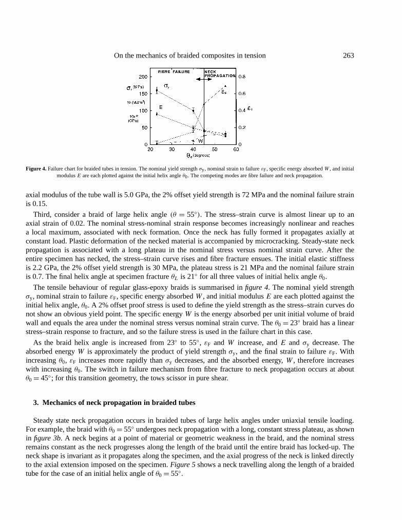
Figure 4. Failure chart for braided tubes in tension. The nominal yield strengthσy, nominal strain to failureεF, specific energy absorbedW , and initialmodulusE are each plotted against the initial helix angleθ0. The competing modes are fibre failure and neck propagation.
axial modulus of the tube wall is 5.0 GPa, the 2% offset yield strength is 72 MPa and the nominal failure strainis 0.15.
Third, consider a braid of large helix angle(θ = 55◦). The stress–strain curve is almost linear up to anaxial strain of 0.02. The nominal stress-nominal strain response becomes increasingly nonlinear and reachesa local maximum, associated with neck formation. Once the neck has fully formed it propagates axially atconstant load. Plastic deformation of the necked material is accompanied by microcracking. Steady-state neckpropagation is associated with a long plateau in the nominal stress versus nominal strain curve. After theentire specimen has necked, the stress–strain curve rises and fibre fracture ensues. The initial elastic stiffnessis 2.2 GPa, the 2% offset yield strength is 30 MPa, the plateau stress is 21 MPa and the nominal failure strainis 0.7. The final helix angle at specimen fractureθL is 21◦ for all three values of initial helix angleθ0.
The tensile behaviour of regular glass-epoxy braids is summarised infigure 4. The nominal yield strengthσy, nominal strain to failureεF, specific energy absorbedW , and initial modulusE are each plotted against theinitial helix angle,θ0. A 2% offset proof stress is used to define the yield strength as the stress–strain curves donot show an obvious yield point. The specific energyW is the energy absorbed per unit initial volume of braidwall and equals the area under the nominal stress versus nominal strain curve. Theθ0= 23◦ braid has a linearstress–strain response to fracture, and so the failure stress is used in the failure chart in this case.
As the braid helix angle is increased from 23◦ to 55◦, εF andW increase, andE and σy decrease. Theabsorbed energyW is approximately the product of yield strengthσy, and the final strain to failureεF. Withincreasingθ0, εF increases more rapidly thanσy decreases, and the absorbed energy,W , therefore increaseswith increasingθ0. The switch in failure mechanism from fibre fracture to neck propagation occurs at aboutθ0= 45◦; for this transition geometry, the tows scissor in pure shear.
3. Mechanics of neck propagation in braided tubes
Steady state neck propagation occurs in braided tubes of large helix angles under uniaxial tensile loading.For example, the braid withθ0= 55◦ undergoes neck propagation with a long, constant stress plateau, as shownin figure 3b. A neck begins at a point of material or geometric weakness in the braid, and the nominal stressremains constant as the neck progresses along the length of the braid until the entire braid has locked-up. Theneck shape is invariant as it propagates along the specimen, and the axial progress of the neck is linked directlyto the axial extension imposed on the specimen.Figure 5shows a neck travelling along the length of a braidedtube for the case of an initial helix angle ofθ0= 55◦.

264 A.-M. Harte, N.A. Fleck
Figure 5. Video images of neck propagation along the axis of a braid under tension, for an initial helix angleθ0 = 55◦ .
3.1. Measured stresses in the neck
In order to construct a model for neck propagation, the local stresses within the neck are measured, asfollows. The longitudinal strain in the braid and the fibre strain were monitored at mid-length of the braid usinga clip gauge and a strain gauge mounted on a representative tow, respectively. The helix angle at selected pointsalong the neck was also recorded. The membrane stresses were determined from the measured axial force onthe braid and from the neck geometry. Later in this paper, we shall compare these measured stresses with themembrane stresses predicted by a micromechanical model of braid deformation.
The neck of the braided tube is treated as a doubly curved membrane with two radii of curvature,R1 andR2,and subjected to a longitudinal stressσ1 and a hoop stressσ2, as shown infigure 6a. Equilibrium dictates that:
σ1
R1+ σ2
R2=1p= 0, (1)
where the pressure differential1p across the mid-plane of the braid vanishes. Axial force equilibrium dictatesthatσ1 is related to the applied axial loadF by:
F = σ12πR2t cosβ, (2)
whereβ is the angle the braid makes with the axial direction, andt is the thickness of the braid as shown infigure 6a. The thickness of the braid does not change significantly with braid angle. The stress state can befound from the applied load via relations (1) and (2), onceR1 andR2 have been measured along the neck.Outside the necked region the stress state is uniaxial tension. At the transition between the un-necked regionand the neck, a sharp corner exists wherein bending stresses cannot be neglected. The true axial membranestressσ1 and true hoop stressσ2 are shown infigure 6bas a function of helix angle within the neck, for the caseθ0 = 55◦. As the angle approaches the lock-up angle, the axial stress downstream of the neck approaches theremote stress and the hoop stress approaches zero. Selected values ofR1,R2, β, σ1, andσ2 are given intable IIas a function of helix angleθ within the neck.

On the mechanics of braided composites in tension 265
Figure 6. (a) Assumed geometry of the neck in the braided tube; (b) The measured longitudinal componentσ1 and hoop componentσ2 of Cauchy stresswithin the neck, forθ0 = 55◦ ; (c) Measured fibre strainεf within the neck. As the neck advances, the helix angleθ decreases from the initial value
θ0 = 55◦ .
Table II. Selected values used in the calculation of membrane stress.
Helix Radii of neck Neck Membrane stresses
angle (mm) angle (MPa)
θ R1 R2 β σ1 σ2
50◦ 29 25.4 38◦ 9.79 8.57
34◦ 104 18.9 12◦ 10.62 1.92
23◦ 141 15.6 5◦ 12.57 1.39
3.2. Resolution of measured stresses in the local fibre axes
In order to develop a micromechanical model of deformation with the neck, the stresses within each layer aremeasured upon treating the braid as a±θ laminate. Consider the typical stress state in the+θ layer, as shownin figure 7a. Symmetry of the±θ laminate dictates that the axial stress componentσ1 and the hoop stresscomponentσ2 equals that for the overall braid, as reported infigure 6b. Additionally, the+θ layer is subjectedto a shear stressσ12= τply and the−θ layer is subjected to a shear stressσ12=−τply, in the Cartesian referenceframe(x1, x2) defined infigure 7a. The shear stressτply is deduced from the measured in-plane stresses(σ1, σ2)
on the braid and from the measured strain along the+θ direction, as follows.
The direct strainεf along the local fibre direction in a+θ layer is measured using a strain gauge adhered toa tow, prior to curing; a typical measurement is reported infigure 6c, for a braid of initial helix angleθ0= 55◦.We note an initial sharp spike in the fibre strain due to bending at the corner at the start of the neck. Once the

266 A.-M. Harte, N.A. Fleck
Figure 7. (a) The stress state within the+θ layer of the braid; (b) The measured stressσt transverse to the+θ fibres, the shear stressτ along the+θfibre direction, and the stressσf in the+θ fibre direction, within the neck of aθ0 = 55◦ braid.
material has entered the neck, the strainεf relaxes to a constant level until the braid locks-up and the strainincreases sharply again. The longitudinal stressσf along the fibre direction in the+θ layer of the braid isestimated from a rule of mixtures calculation of the modulus of the layer in the fibre direction.
Upon rotating axes from the axial direction to the+θ direction, the components of stress in a+θ layer aregiven by
σf = σ1 cos2 θ + σ2 sin2 θ + τply sin 2θ, (3a)
σt= σ1 sin2 θ + σ2 cos2 θ − τply sin 2θ, (3b)
and
τ = 1
2(σ2− σ1)sin 2θ + τply cos 2θ, (3c)
whereσt and τ are the stress transverse to the fibre direction and the shear stress along the fibre direction,respectively. Equations (3a–c) are used to deduceτply, σt andτ throughout the neck from the measured valuesof σ1, σ2 andσf . The inferred distribution of(σf, σt, τ ) within the neck is plotted infigure 7b. We note that thetransverse stressσt remains compressive within the neck although we shall see below that the kinematics ofdeformation imply that the transverse strain is initially tensile. A micromechanical model for the stress statewithin the neck is developed in the following section and its predictions are compared with the experimentalvalues.
4. Simple micromechanical models for the tensile behaviour of braided tubes
4.1. Prediction of elastic modulus
Laminate plate theory (LPT) is commonly used to predict the stiffness of fibre laminates from the elasticproperties of individual laminae; it is based on the assumption that the strain state does not vary in the through-thickness direction. In the present study, laminate plate theory is used to predict the axial modulus of the braidsby treating them as±θ laminates. The predicted elastic moduli are compared with the measured values in

On the mechanics of braided composites in tension 267
Figure 8. The axial elastic modulusE versus the initial helix angleθ0. Values ofE from laminate plate theory (LPT), and from the tensile andcompressive tests are shown forθ0 = 23◦ , 40◦, and 55◦ . The compression results are taken from (Harte and Fleck, 1999). Results are omitted for
θ = 45◦ as a clip gauge was not used in these tests for the measurement ofE.
tension and compression infigure 8. (The compression results were taken from (Harte and Fleck, 1999).) Theexperimental and theoretical values of axial elastic modulus are in good agreement, to within material scatter.
4.2. Braid kinematics
The regular braids of this study are comprised of two sets of helical tows winding in opposite directionsaround a cylinder. As a braid is pulled in tension, the tows scissor like the slats of a garden trellis; the helixangle decreases, and the tube increases in length and decreases in diameter. The tows continue to scissor untilthey become tightly packed and the braid locks-up at a helix angleθL.
Post-failure microscopy of the glass/epoxy braids reveals that the pattern of microcracking within the matrixbetween the tows is accompanied on a smaller scale by microcracking of the matrix between individual fibresof each tow. This suggests that the kinematic description of scissoring of the tows also describes the relativemotion of fibres within each tow. In the following analysis, we shall smear out the fibres and matrix, and defineoverall stress and strain measures for the smeared-out continuum in terms of the helix angleθ .
It is convenient to calculate the strain rate within the braid using rotating orthonormal axes(x1′, x2′), with thex1′-direction aligned with the fibres of orientationθ as shown infigure 9. The fibres in both theθ and the−θdirections are assumed to be inextensional; thus, in the(x1′, x2′) reference frame we haveε1′1′ = 0 and the strainrate components of interest are the strain rate transverse to the fibreset ≡ e2′2′ and the shear strain rateγ = 2ε1′2′along the fibre direction. In order to define(et, γ ) we consider the relative velocities of neighbouring fibres.The true transverse strain rateet is given by the separation velocity of the centre-lines of two neighbouringfibres along thex2′-direction divided by their current separation,
et = 2
tan2θθ . (4a)
The shear strain rateγ is defined by the rate of scissoring 2θ of fibres in theθ and the−θ directions, such that
γ = 2ε1′2′ = −2θ . (4b)

268 A.-M. Harte, N.A. Fleck
Figure 9. The predicted transverse strainet and shear strainγ within the braid, for an initial helix angleθ0= 60◦ .
Integration ofγ andet from an initial helix angleθ0 to a current angleθ gives
γ = 2(θ0− θ) (5a)
and
et = ln(
sin2θ
sin 2θ0
). (5b)
The transverse and shear strains are sketched infigure 9 for the caseθ0 = 60◦: the shear strain increaseswith decreasing helix angleθ whereas the transverse strainet reaches a maximum atθ = 45◦, then drops tonegative values with decreasingθ . The negative transverse strains are associated with crumbling of the matrix.For an initial helix angleθ0 > 45◦ the matrix shears and initially dilates under axial extension; the distancebetween neighbouring fibres reaches a maximum atθ0= 45◦, at which point the matrix deforms in pure shear.For θ0< 45◦ the matrix shears and compacts under axial extension.
The axial strain of the braidεa is related to the current braid angleθ and to the initial braid angleθ0 by
εa= cosθ − cosθ0
cosθ0, (6)
where 2cosθ0 is the initial axial length of a braid unit cell and 2cosθ is the current length.
5. A constitutive law for the braid within the neck
A constitutive law for the braided material must be found in order to predict the plastic dissipation duringneck propagation; an energy balance condition can then be used to predict the axial load for steady state neckpropagation.
Figure 10ashows three scanning electron microscope (SEM) images of the state of the matrix within atypical neck; it shows that the matrix between the fibres breaks up into arrays of parallel microcracks with

On the mechanics of braided composites in tension 269
(a)
(b)
Figure 10. (a) Scanning electron microscope (SEM) images of the crack state within the neck, for the caseθ0 = 55◦ ; (b) Schematic of the neck in thebraid showing the damage evolution with decreasingθ . The matrix disintegrates into an array of stubby beams, and the beams rotate as the fibres scissor.
intervening short, stubby beams. The damage sequence is sketched infigure 10b. Arrays of tensile microcracksform approximately perpendicular to the local loading direction. With continued loading, the fibres scissor andthe beam-like ligaments within the matrix rotate until eventually they align perpendicular to the fibres. At largerstrains the beams fracture and the matrix becomes rubble.

270 A.-M. Harte, N.A. Fleck
Figure 11. Representation of the matrix as an array of stubby beams of length` and thicknesst between fibres of spacingh, inclined with respect tothe fibres at an angleψ . Each beam is subjected to an axial loadP , a shear loadS and a momentM per unit thickness into the page.
The damaged matrix is modelled as a series of stubby beams using the yield surface for a rigid, ideallyplastic beam subjected to end moments and a longitudinal load (Green, 1954a, b). The predicted transverse andshear stresses are then compared with the measured stresses determined from the previous section. The elasticdeformation is small and can be neglected.
5.1. The yield surface
The damaged matrix is treated as a series of stubby beams of length` and thicknesst made from rigid,ideally plastic material, seefigure 11. The beams are subjected to both an axial forceP and a momentM perunit depth, upon resolving the macroscopic traction due to the shear stressτ and transverse stressσt as definedin equations (3a–c). Green (1954a, b) has shown that the collapse locus forP andM for stubby beams isadequately represented by that for a long thin beam:
8(M,P )=(P
P0
)2
±(M
M0
)− 1= 0, (7)
whereP0 = 2kt , M = S`/2 andM0 = t2k/2. Here,k is the shear yield strength of the matrix andS is theresultant shear force, as shown infigure 11. Force resolution gives
S = (τ cosψ + σt sinψ)t
cosψ(8a)
and
P = (−τ sinψ + σt cosψ)t
cosψ, (8b)

On the mechanics of braided composites in tension 271
Figure 12.The yield surface of the matrix beams in axes of transverse stressσt and shear stressτ . As the fibres scissor, the beams rotate, and the yieldsurface rotates in stress space.
where the crack angleψ is defined infigure 11. The yield locus (7) can then be rewritten as
8(τ,σt)= 1
cosψ
`
t
(τ
kcosψ + σt
ksinψ
)+ 1
4
1
cos2ψ
(−τk
sinψ + σt
kcosψ
)2
− 1= 0. (9)
Note that the cracks have an initial angleψ0 and rotate to an orientation perpendicular to the fibres(ψ = 0◦).The yield surfaces forψ = 0◦ andψ = 45◦ simplify to:
8= `t
τ
k+ 1
4
(σt
k
)2
− 1= 0 forψ = 0◦ (10a)
and
8= `t
(τ
k+ σt
k
)+ 1
4
(−τk+ σt
k
)2
− 1= 0 forψ = 45◦ (10b)
and are plotted infigure 12for selected values of/t andψ . In subsequent calculations we shall take`/t = 3to correspond to the value observed from the SEM images of the neck. A feature of the yield surface is thepronounced vertex at each end. At these vertices the strain rate can be in any direction within the forward coneof normals, implying that the stress state is usually at a vertex.
5.2. Kinematics of matrix deformation
To proceed, an expression is obtained for the motion of the matrix beams as the braid deforms. Therelationship between the velocity of the fibres tangential to the fibre direction and perpendicular to the fibredirection,us andut, and the strain rates,γ andet, in the composite is given by:
us
h= γ
1− Vf(11)

272 A.-M. Harte, N.A. Fleck
andut
h= et
1− Vf, (12)
whereh is the distance between fibres andVf is the fibre volume fraction. Here,us us is the tangential relativedisplacement of two fibres andut is the normal relative displacement of two fibres, as shown infigure 11.
The rotation rateψ is related to the beam motion by:
−ψ = 1
`
(uscosψ + ut sinψ
). (13)
Upon substituting (11) and (12) into (13) and making use of the connectionh= `cosψ , the rate of change ofthe crack inclinationψ is related to the strain rateet andγ by
ψ =−cos2ψ
1− Vfγ − cosψ sinψ
1− Vfet. (14)
Recall that the shear and normal strain rate,γ and et, have already been related to the helix angle rateθ byequations (4a) and (4b).
5.3. The associated flow rule
Associated plastic flow is assumed such that the plastic strain rateεij is given by
εij = 1
H
∂8
∂σij
∂8
∂σklσkl, (15)
where the overall hardening modulusH remains to be specified. Recall that the underlying matrix materialis taken as rigid, ideally plastic and so the hardening modulusH is associated with the geometric hardeningaccompanying beam rotation, and not due to intrinsic material strengthening. The strain rates can be specifiedby the shear strain rate and the strain rate normal to the fibreset such that
γ = 1
H
∂8
∂τ
(∂8
∂ττ + ∂8
∂σtσt
)(16a)
and
et = 1
H
∂8
∂σt
(∂8
∂ττ + ∂8
∂σtσt
). (16b)
The consistency relation for continued plastic yielding reads
8= ∂8∂ττ + ∂8
∂σtσt + ∂8
∂ψψ = 0. (17)
From equations (16) and (17) and the kinematical relation (13), the strain rate can be rewritten as:
γ = 1
H
∂8
∂τ
∂8
∂ψ
h
`(1− Vf)
(γ cosψ + et sinψ
), (18a)
en = 1
H
∂8
∂σt
∂8
∂ψ
h
`(1− Vf)
(γ cosψ + et sinψ
)(18b)
On the mechanics of braided composites in tension 273
and the hardening modulusH follows by eliminatingγ andet from the two simultaneous equation (18a and b)to give
H−1=(∂8
∂τcosψ + ∂8
∂σtsinψ
)∂8
∂ψ
cosψ
1− Vf. (19)
We now have a complete formulation for each layer of the composite. The yield function8 is a function ofthe variables,τ , σt, k, andψ . From the flow rule (15) and the consistency relation (17) the strain ratesγ andet
are known. The kinematical relation (14) providesψ in terms ofγ andet.
6. Comparison of predicted and measured stress state in the neck
The equations developed above provide a constitutive description for the braid. Due to the shape of the yieldsurface the stress is at a vertex of the yield surface unless|ut/us| is close to zero. At each vertex we haveM = 0and|P | = 2kt . The normal and shear stresses then simplify to:
τ
k= 2sinψ cosψ (20a)
andσt
k=−2cos2ψ. (20b)
The current beam orientation is given byψ =ψ0+ 21θ where1θ ≡ θ − θ0, resulting in
τ
k= 2sin(ψ0+ 21θ)cos(ψ0+ 21θ) (21a)
andσt
k=−2cos2(ψ0+ 21θ). (21b)
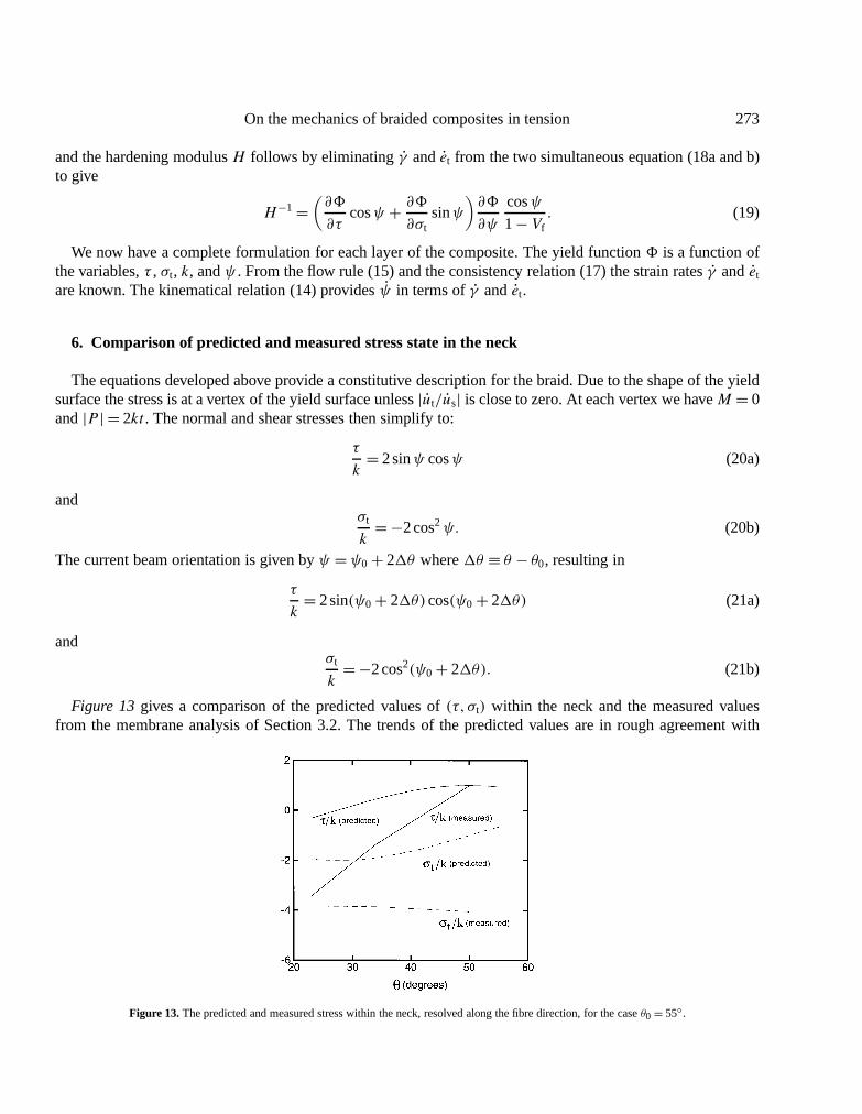
Figure 13gives a comparison of the predicted values of(τ, σt) within the neck and the measured valuesfrom the membrane analysis of Section 3.2. The trends of the predicted values are in rough agreement with
Figure 13.The predicted and measured stress within the neck, resolved along the fibre direction, for the caseθ0= 55◦.

274 A.-M. Harte, N.A. Fleck
the measured values. The largest discrepancies in shear stress occurs at small values of the helix angleθ . Atthese helix angles the matrix exists as rubble rather than as an array of stubby beams and the constitutive modeldeveloped above is no longer applicable.
6.1. Prediction of the neck propagation stress
In general, a Maxwell-type energy construction cannot be used to predict the applied load for the propagationof an instability, such as a neck, within a flow theory solid. However, in the present case, the deformation statewithin the neck of the braid is governed by the single degree of freedom,θ , and thus the loading path in stressstate is known. An energy balance method can then be used in order to estimate the propagation stress.
The internal energy dissipated in scissoring the fibres fromθ = θ0 to a final angleθ = θL is
W = V0
∫ γL
0
[τV
V0
]dγ + V0
∫ eLt
0
[σtV
V0
]det, (22)
whereγL ≡ γ (θ = θL) andeLt ≡ et(θ = θL) are given by (5), andτ andσt are the macroscopic shear stress andtransverse stress in the current configuration, in the local fibre axes. The ratio of current volumeV to the initialvolumeV0 of a braid element is given by
V
V0= sin2θ
sin 2θ0. (23)
Since the scissoring of the braid is dictated by a single degree of freedomθ we can re-write (22) as
W = V0
∫ θL
θ0
[−τ 2sin 2θ
sin 2θ0
]dθ + V0
∫ θL
θ0
[σt
2 cos 2θ
sin2θ0
]dθ (24)
and the energy balance can be written:
P(L1−L0)=A0L0
{∫ γ
0
[τ
sin 2θ
sin 2θ0
]dγ +
∫ et
0
[σ
sin 2θ
sin 2θ0
]det
}. (25)
The left-hand side of the equation represents the energy contribution of the applied load,P in changing thelength of a section fromL0 to L1; the final lengthL1 is given byL0εa, where the axial strainεa, as defined in(6), is evaluated atθ = θL. The right-hand side is the energy per unit initial volume due to material deformation,multiplied by the original volume of the wall of the tubeA0L0. The above integral has been evaluated for braidswith initial helix angles in the rangeθ0= 60◦ to θ0= 45◦, using relations (21a and b) forτ andσt and (5a andb) for γ andet. (For anglesθ0 less than 45◦ neck propagation does not occur.)
The predicted propagation loadP , energy absorption per unit volumeW , and final axial strainεa are plottedin figure 14for an assumed lock-up helix angleθL = 21◦. The trends are as expected: the energy absorbedand the final axial strain increase with increasing initial helix angle and the propagation load decreases. Thepredictions may be compared with the measured propagation load for the caseθ = 55◦ and θL = 21◦. Inthe experiment, the initial wall cross-sectional area was 200 mm2, and the shear strength of the epoxy was22 MPa from a uniaxial tensile test on a±45◦ braid (seefigure 3). The predicted propagation load, 9.9 kN, isapproximately twice the measured value of 4.0 kN. The discrepancy is not surprising considering the limitedaccuracy of the beam model for the cracked matrix. Similar agreement is noted for the absorbed energyW , butgood agreement is found between the final axial strain of 0.60, given by equation (6) and the observed lock-upstrain of 0.62.

On the mechanics of braided composites in tension 275
Figure 14. The normalised propagation loadP/2πrtk, normalised energy absorption per unit volumeW/k and the final axial strainεa for neckpropagation as a function of the initial helix angleθ0. θL = 21◦.
7. Concluding remarks
Tubular braids fail in tension by fibre failure for small initial helix angles and by neck propagation for largeinitial helix angles. The switch in failure mode from fibre failure to neck propagation is accompanied by a largeincrease in energy absorption and strain to failure but by a large drop in yield strength.
Attention has been focused on the case of an initial braid angleθ0 greater than 45◦. The stress state in theneck is deduced from the observed neck shape using a membrane analysis and from strain gauges impregnatedin the braid prior to epoxy infiltration. A micromechanical model has been developed of the deformation statewithin the neck. The predicted propagation stress increases, whereas the strain to lock-up and the absorbedenergy decrease with increasing helix angle, in agreement with the trends observed experimentally. The limitedresults of the current study suggest that braided composites have potential as practical energy absorbers: theydeform in tension at almost constant stress over large extensional strains.
Acknowledgements
The authors wish to thank the Natural Sciences and Engineering Research Council of Canada, the NewtonTrust, and ONR through the grant number N0014-91-J-1916 for their financial support and CambridgeConsultants Ltd for the provision of test materials.
References
Chater E., Hutchinson J.W., 1984a. On the propagation of bulges and buckles. J. Appl. Mech. 51, 269–277.Chater E., Hutchinson J.W., 1984b. Mechanical analogs of coexistent phases. In: Phase Transformations and Material Instability in Solids, Academic
Press, Inc., pp. 21–36.Chou T.-W., 1992. Microstructural Design of Fiber Composites. Cambridge Solid State Science Series, Cambridge University Press.Green A.P., 1954a. A theory of the plastic yielding due to bending of cantilevers and fixed-ended beams. Part 1. J. Mech. Phys. Solids 8, 1–15.Green A.P., 1954b. A theory of the plastic yielding due to bending of cantilevers and beams. Part II. J. Mech. Phys. Solids 8, 143–155.Harte A.-M., Fleck N.A., 1999. Deformation and failure mechanisms of braided composite circular tubes in compression and torsion. Eur. J. Mech.
A, to appear.Kyriakides S., Chang Y.-C., 1990. On the inflation of a long elastic tube in the presence of axial load. Int. J. Solids Structures 26 (9/10), 975–991.Kyriakides S., 1994. Propagating instabilities in structures. In: Advances in Applied Mechanics, Vol. 20, Academic Press, Inc., pp. 67–189.